Embed Size (px)
Citation preview
MODEL G9749VARIABLE SPEED
DRILL PRESSOWNER'S MANUAL
COPYRIGHT © SEPTEMBER, 2006 BY GRIZZLY INDUSTRIAL, INC.WARNING: NO PORTION OF THIS MANUAL MAY BE REPRODUCED IN ANY SHAPE
OR FORM WITHOUT THE WRITTEN APPROVAL OF GRIZZLY INDUSTRIAL, INC. #TS8502 PRINTED IN TAIWAN

�������������������������������������������������������������������������������������������������������������������������������������
������������������������������������������������������������������������������������������������������������������������������������������������������������������
�������������������������������������������������������������������������������������������������������������������������������������������������������������������������������������������������������������������������������������������������������������������������������������������������������������������������������������������������������������������������������������������������������
�������������������������������������������������������������������������������������������������������������������������������������������
������������������������������������������������������������������������������������������������������������������������������������������������������������������������������������������������������������������������������������������������������
�� ������������������������������ �������������������������������������������������������������������� ����������������������������������������������������
�������������������������������������������������������������������������������������������������������������������������������������������������������������������������������������������������������������������������������������������������������������������������������������������������������

Table of ContentsINTRODUCTION ............................................................................................................................... 2
Foreword .................................................................................................................................... 2Contact Info ................................................................................................................................ 2Machine Data Sheet ................................................................................................................... 3Identification ............................................................................................................................... 5
SECTION 1: SAFETY ....................................................................................................................... 6Safety Instructions for Machinery ............................................................................................... 7Additional Safety for Drill Presses .............................................................................................. 8
SECTION 2: CIRCUIT REQUIREMENTS ........................................................................................ 9110/220V Operation ................................................................................................................... 9Grounding ................................................................................................................................. 10Extension Cords ....................................................................................................................... 10
SECTION 3: SETUP ....................................................................................................................... 11Setup Safety ............................................................................................................................. 11Items Needed for Setup ........................................................................................................... 11Site Considerations .................................................................................................................. 11Unpacking and Lifting ............................................................................................................... 12Mounting to Shop Floor ............................................................................................................ 13Inventory ................................................................................................................................... 14Clean Up .................................................................................................................................. 14Assembly .................................................................................................................................. 15Test Run and Spindle Break-In ................................................................................................ 16
SECTION 4: OPERATIONS ........................................................................................................... 17Installing Drill Chuck ................................................................................................................. 17Installing/Removing Drill Bits .................................................................................................... 18Changing Speeds ..................................................................................................................... 18Choosing Speeds ..................................................................................................................... 19Drilling ...................................................................................................................................... 20Quill Travel ............................................................................................................................... 20Table Adjustments ................................................................................................................... 22Headstock Rotation .................................................................................................................. 22Removing/Installing Arbor and Chuck ...................................................................................... 23
SECTION 5: ACCESSORIES ......................................................................................................... 25SECTION 6: MAINTENANCE ........................................................................................................ 26
Schedule .................................................................................................................................. 26Unpainted Cast Iron ................................................................................................................. 26Lubrication ................................................................................................................................ 26
SECTION 7: SERVICE ................................................................................................................... 27About Service ........................................................................................................................... 27Troubleshooting ........................................................................................................................ 27Electrical Components ............................................................................................................. 29Wiring Diagram ........................................................................................................................ 30Headstock Parts Breakdown .................................................................................................... 31Headstock Components Parts Breakdown .............................................................................. 32Variable Speed Parts Breakdown ............................................................................................ 33Base Parts Breakdown ............................................................................................................. 34Label Placement ...................................................................................................................... 37
WARRANTY AND RETURNS ........................................................................................................ 38

-2- G9749 Variable Speed Drill Press
If you have any comments regarding this manual, please write to us at the address below:
Grizzly Industrial, Inc.C/O Technical Documentation Manager
P.O. Box 2069Bellingham, WA 98227-2069E-Mail: [email protected]
We stand behind our machines. If you have any service questions or parts requests, please call or write us at the location listed below.
Grizzly Industrial, Inc.1203 Lycoming Mall Circle
Muncy, PA 17756Phone: (570) 546-9663
Fax: (800) 438-5901E-Mail: [email protected] Site: http://www.grizzly.com
Foreword
INTRODUCTION
Contact Info
We are proud to offer the Model G9749 Variable Speed Drill Press. This machine is part of a grow-ing Grizzly family of fine metalworking machinery. When used according to the guidelines set forth in this manual, you can expect years of trouble-free, enjoyable operation and proof of Grizzly’s com-mitment to customer satisfaction.
We are pleased to provide this manual with the Model G9749. It was written to guide you through assembly, review safety considerations, and cover general operating procedures. It repre-sents our effort to produce the best documenta-tion possible.
The specifications, drawings, and photographs illustrated in this manual represent the Model G9749 as supplied when the manual was pre-pared. However, owing to Grizzly’s policy of con-tinuous improvement, changes may be made at any time with no obligation on the part of Grizzly. For your convenience, we always keep current Grizzly manuals available on our website at www.grizzly.com. Any updates to your machine will be reflected in these manuals as soon as they are complete. Visit our site often to check for the lat-est updates to this manual!

G9749 Variable Speed Drill Press -3-
The information contained herein is deemed accurate as of 3/18/2007 and represents our most recent product specifications.Due to our ongoing improvement efforts, this information may not accurately describe items previously purchased. PAGE 1 OF 2Model G9749
MACHINE DATASHEET
Customer Service #: (570) 546-9663 · To Order Call: (800) 523-4777 · Fax #: (800) 438-5901
MODEL G9749 VS DRILL PRESSProduct Dimensions:
Weight.............................................................................................................................................................. 615 lbs.Length/Width/Height....................................................................................................................... 33-1/8 x 22 x 75 in.Foot Print (Length/Width)............................................................................................................................. 26 x 19 in.
Shipping Dimensions:
Type............................................................................................................................................Wood Crate/Slats 2 SContent............................................................................................................................................................ MachineWeight.............................................................................................................................................................. 776 lbs.Length/Width/Height............................................................................................................................. 37 x 29 x 72 in.
Electrical:
Switch...........................................................................................................................................................ReversibleSwitch Voltage...................................................................................................................................................... 220VCord Length............................................................................................................................................................ 7 ft.Cord Gauge....................................................................................................................................................14 gaugeRecommended Breaker Size............................................................................................................................ 20 ampPlug.........................................................................................................................................................................Yes
Motors:
Main
Type.................................................................................................................. TEFC Capacitor Start InductionHorsepower...........................................................................................................................................1-1/2 HPVoltage........................................................................................................................................................220VPrewired......................................................................................................................................................220VPhase........................................................................................................................................................ SingleAmps..........................................................................................................................................................16/8ASpeed.................................................................................................................................................1725 RPMCycle..........................................................................................................................................................60 HzNumber Of Speeds........................................................................................................................................... 1Power Transfer .........................................................................................................................................V-BeltBearings........................................................................................................ Shielded, Permanently Lubricated
Main Specifications:
Construction
Table Construction............................................................................................................................... Cast IronSpindle Housing Construction.............................................................................................................. Cast IronColumn Construction............................................................................................................... Ground Cast IronHead Construction................................................................................................................................Cast IronBase Construction................................................................................................................................ Cast IronPaint.......................................................................................................................................................... Epoxy
Head Information
Head Swivel.......................................................................................................................................... 360 deg.

-4- G9749 Variable Speed Drill Press
The information contained herein is deemed accurate as of 3/18/2007 and represents our most recent product specifications.Due to our ongoing improvement efforts, this information may not accurately describe items previously purchased. PAGE 2 OF 2Model G9749
Other Related Information
Base Length............................................................................................................................................... 26 in.Base Width...........................................................................................................................................18-1/2 in.Quill Hold Type.................................................................................................................... Lock Lever with GibQuill Diameter...............................................................................................................................................3 in.Depth Stop Type.............................................................................................Threaded Rod with Positive StopColumn Diameter................................................................................................................................... 4-1/2 in.
Spindle Information
Spindle Taper.............................................................................................................................................MT#3Spindle Travel........................................................................................................................................ 6-1/2 in.Dist From Spindle To Column................................................................................................................ 9-3/4 in.Dist From Spindle To Table................................................................................................................. 28-3/4 in.Dist From Spindle To Base........................................................................................................................ 50 in.
Table Information
Table Length........................................................................................................................................ 21-3/4 in.Table Width.......................................................................................................................................... 19-1/2 in.Table Thickness........................................................................................................................................... 2 in.Floor To Table Height......................................................................................................................... 18 - 43 in.Vertical Table Movement................................................................................................ Crank Handle OperateTable Swivel Around Column................................................................................................................360 deg.Maximum Movement Of Work Table..........................................................................................................25 in.No. Of T Slots....................................................................................................................................................2T Slot Width...............................................................................................................................................1/2 in.T Slot Length........................................................................................................................................15-1/2 in.
Operation Information
Swing................................................................................................................................................... 19-1/2 in.Drilling Capacity..................................................................................................................................... 1-1/4 in.No Of Spindle Speeds........................................................................................................................... VariableRange Of Spindle Speeds........................................................................................................ 300 - 2000 RPMDrill Chuck Type......................................................................................................................... JT6 Key ChuckDrill Chuck Size......................................................................................................................................... 1/2 in.End Milling Cap......................................................................................................................................... 3/4 in.Face Milling Cap...........................................................................................................................................3 in.
Other Specifications:
ISO Factory ................................................................................................................................................... ISO 9001Country Of Origin ..............................................................................................................................................TaiwanWarranty ............................................................................................................................................................ 1 YearSerial Number Location ...................................................................................................... ID Label on Head CastingAssembly Time ........................................................................................................................................... 10 minutes
Features:
Graduations in 0.001 InchesManual Fine Down FeedQuill Lock and Depth StopMT #3 Spindle TaperVariable Speed1-1/2HP MotorTable and Base are Cast Iron
G9749 Variable Speed Drill Press -5-
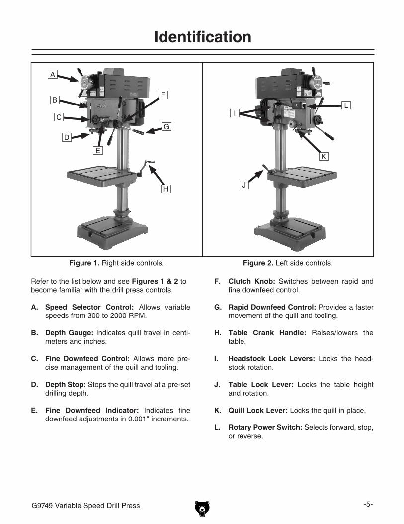
Figure 1. Right side controls.
Identification
Figure 2. Left side controls.
Refer to the list below and see Figures 1 & 2 to become familiar with the drill press controls.
A. Speed Selector Control: Allows variable speeds from 300 to 2000 RPM.
B. Depth Gauge: Indicates quill travel in centi-meters and inches.
C. Fine Downfeed Control: Allows more pre-cise management of the quill and tooling.
D. Depth Stop: Stops the quill travel at a pre-set drilling depth.
E. Fine Downfeed Indicator: Indicates fine downfeed adjustments in 0.001" increments.
F. Clutch Knob: Switches between rapid and fine downfeed control.
G. Rapid Downfeed Control: Provides a faster movement of the quill and tooling.
H. Table Crank Handle: Raises/lowers the table.
I. Headstock Lock Levers: Locks the head-stock rotation.
J. Table Lock Lever: Locks the table height and rotation.
K. Quill Lock Lever: Locks the quill in place.
L. Rotary Power Switch: Selects forward, stop, or reverse.
A
B
C
D
E
F
G
H
I
J
K
L
-6- G9749 Variable Speed Drill Press
��� ������� ���� �������� ���������������� ���������� ��������������������� ������ ���� ������ ������������������������
��� ����� ������� ��������� ��� ����������������������������������������������������� �������� ��������������� ���������������������� ����������� ����� ��������� ��� ���������������������������������������������
��� ������ �������� ���������� �������������������������������������������������������������������������������������������������������������
���� ����������������������������������������������������������������������� �������� ������� �������� ��� �����������������
��� ������� ���� ����� ��������������������������������������������������� ��������� ����������� ���������� ������� ���������� ������������ �����������������������
��� ������� ����� �� ������ �������������������� ����� �������������������� ����� ��������� ����������� ����� ���� ������ ������� ����������������������
��������������������������������������������������������������������������
����������������������������������������������������������������������������������������������������������������������������������������������������������������������������������������������������������������������������������������������������������������������������������������������������������������������������������������������������������������������������������������������������������
�����������������������������������������������������������������������������������������������������������������������������������������������������������������
�����������������������������������������������������������������������������������������������������������
����������������������������������������������������������������������������������������������������������
��������������������������������������������������������������������������������������������������������
���������������������������������
�����������������

G9749 Variable Speed Drill Press -7-
��� ����� ������ �������� ���� ���������� ����������� ���������� ����������� ����������� ����� �������������������������������������������������������������
��� �������������������������������������� ���� ��������� ���� ��������� �� ����� �����������������������������
���� ���������������������������������������� ������� ���������� ���� �������������������������
���� ������ ������ ����� �������� ������������������������������������������������������ �������� �����������������������������������������������������
�������� ���� ���� ��� ������������������������������� ��������������� ��� ���������� ����������� ���������������������������������������������������
�����������������������������������������������������������������������������������������
���� ���������������������������������������������������������������������������������������������������������������� ������ ������� ���������� ����������������������������������������������
���� ������� ����������� ����� ������������� ������� �������������������������������������� ��� ������������������������������������
���� ��������� ���������� ����� ��������������������������������������������������������������������������������������������������������������������������������
���������� ����� ������� ���� ��� ���������� ����� ���������� �����������������������
��������������������������������������������� ���������� ����� ����
�������������������������������������������������������������������������� ����������������������
���� ������ ���� �������� ������������������������������������������������������������������������������������������������������������������������� ��������� ��������������� ������������������ ������������������������������������������
���� ���� ������������ �������������������������������������������������������������� ������������� ��������� �������������������������������������
�������� ���� ������ ���������������� ��������������������������������������������������������������
���� ������� ����������� ���� ������� ���������� �������� ������������������������������� �� �������� ���������� ��������� �������������������������������������������������������
���� ���������������������������������������������������������������
���� ����� ��������� ���� ������������������ ������� ���������������������������������������������������������������������������
���� ������� ����� ������� ����������� ������ ������� ��������������������
������������� ����� ���� ��� ������������� ���� ������������ �������� ��� ������� ��������������������������������������������������� ����� ��� ����� ���� ���� �������� ��� ������������������������������������������������������������������
Safety Instructions for Machinery

-8- G9749 Variable Speed Drill Press
1. EYE/FACE/HAND PROTECTION. A face shield used with safety glasses is rec-ommended. Always keep hands and fin-gers away from the drill bit. Never hold a workpiece by hand while drilling! DO NOT wear gloves when operating the drill.
2. SECURING BIT. Properly tighten and
securely lock the drill bit in the chuck.
3. CORRECT BIT. Use only round, hex, or triangular shank drill bits.
4. ADJUSTING KEYS AND WRENCHES. Remove all adjusting keys and wrenches before turning the machine ON.
5. DRILLING SHEET METAL. Never drill sheet metal unless it is securely clamped to the table.
6. SURFACE/WORKPIECE PREP. Never turn the drill press ON before clearing the table of all objects (tools, scraps, etc.). DO NOT drill material that does not have a flat surface, unless a suitable support is used.
7. DAMAGED TOOLS. Never use drill bits in poor condition. Dull or damaged drill bits are hard to control and may cause serious injury.
Additional Safety for Drill Presses8. DRILL OPERATION. Never start the drill
press with the drill bit in contact with the workpiece. Feed the drill bit evenly into the workpiece. Back the bit out frequently to clear deep holes.
9. CLEARING CHIPS. Turn the machine OFF and clear chips and scrap pieces with a brush. Disconnect power, remove drill bit, and clean table before leaving the machine.
10. OPERATING SPEED. Always operate your drill press at speeds that are appropriate for the drill bit size and the material that you are drilling.
11. MOUNTING WORKPIECES. Use clamps or vises to secure workpiece before drill-ing. Position work so you avoid drilling into the table.
12. TABLE LOCK. Make sure the table lock is tightened before starting the drill press.
13. MAINTENANCE. Never do maintenance on the machine when it is connected to power.
14. EXPERIENCING DIFFICULTIES. If at any time you are experiencing difficulties performing the intended operation, stop using the machine! Contact our Technical Support at (570) 546-9663.
No list of safety guidelines can be complete. Every shop environment is different. Always consider safety first, as it applies to your individual working conditions. Use this and other machinery with caution and respect. Failure to do so could result in serious per-sonal injury, damage to equipment, or poor work results.
Like all machines there is danger associated with this machine. Accidents are frequently caused by lack of familiarity or failure to pay attention. Use this machine with respect and caution to lessen the possibility of operator injury. If normal safety precautions are overlooked or ignored, serious personal injury may occur.

G9749 Variable Speed Drill Press -9-
Serious personal injury could occur if you connect the machine to the power source before you have completed the setup pro-cess. DO NOT connect the machine to the power source until instructed to do so.
110/220V Operation
SECTION 2: CIRCUIT REQUIREMENTS
Amperage DrawThe Model G9749 features a 110/220V motor that is prewired for 220V and draws the following amps under maximum load:
Motor Draw at 110V .............................. 16 AmpsMotor Draw at 220V ............................... 8 Amps
Circuit RequirementsWe recommend connecting your machine to a dedicated and grounded circuit that is rated for the amperage given below. Never replace a circuit breaker on an existing circuit with one of higher amperage without consulting a qualified electri-cian to ensure compliance with wiring codes. If you are unsure about the wiring codes in your area or you plan to connect your machine to a shared circuit, consult a qualified electrician.
110V Circuit ...........................................30 Amps220V Circuit ...........................................20 Amps
Plug/Receptacle TypeWe recommend using one of the following plugs for your machine on a dedicated circuit only (see Figures 3 & 4 for examples):
110V Plug & Receptacle ............................ L5-30220V Plug (provided) & Receptacle .............6-15
Figure 4. 6-15 plug and receptacle.
Figure 3. L5-30 plug and receptacle.
NOTICEThe Model G9749 is prewired for 220V oper-ation. If you plan to rewire your machine for 110V, you must change the motor wir-ing, plug, and power receptacle. Consult a qualified electrician before attempting to rewire your machine!

-10- G9749 Variable Speed Drill Press
In the event of an electrical short, grounding reduces the risk of electric shock. The grounding wire in the power cord must be properly connected to the grounding prong on the plug; likewise, the outlet must be properly installed and grounded. All electrical connections must be made in accor-dance with local codes and ordinances.
220V OperationWe do not recommend the use of extension cords. Instead, arrange the placement of your equipment and the installed wiring to eliminate the need for extension cords.
If you must use an extension cord at 220V with your machine:
• Use at least a 14 gauge cord no longer than 50 feet!
• The extension cord must also contain a ground wire and plug pin.
• A qualified electrician MUST size cords over 50 feet long to prevent motor damage.
110V OperationWe do not recommend the use of extension cords. Instead, arrange the placement of your equipment and the installed wiring to eliminate the need for extension cords.
If you must use an extension cord at 110V with your machine:
• Use at least a 12 gauge cord no longer than 50 feet!
• The extension cord must also contain a ground wire and plug pin.
• A qualified electrician MUST size cords over 50 feet long to prevent motor damage.
Extension CordsGrounding
Electrocution or fire could result if this machine is not grounded correctly or if your electrical configu-ration does not comply with local and state codes. Ensure compliance by checking with a qualified electrician!

G9749 Variable Speed Drill Press -11-
Wear safety glasses dur-ing the entire setup pro-cess!
This machine presents serious injury hazards to untrained users. Read through this entire manu-al to become familiar with the controls and opera-tions before starting the machine!
Setup Safety
SECTION 3: SETUP
The following items are needed to complete the setup process, but are not included with your machine:
Description Qty• Assistance .......................1 or more persons• 1⁄2-Ton Forklift or Crane, and Operator (for lifting/moving) ....................................... 1• 1⁄2-Ton Lifting Straps (for lifting/moving) ..... 2• 1⁄2-Ton Hook (for lifting/moving) .................. 1• Safety Glasses (for each person) .............. 1• Degreaser/Solvent (for clean-up) As needed• Shop Rags (for clean-up) ............As needed• Open end wrench 9⁄16" ................................ 1
Items Needed for Setup
Floor LoadRefer to the Machine Data Sheet on Page 3 for the weight and footprint specifications of your machine. Some residential floors may require additional reinforcement to support both the machine and operator.
Placement LocationWhen establishing a location for your new machine, consider existing and anticipated needs, size of material to be processed through this machine, and space for auxiliary stands, work tables or other machinery. See Figure 5 for the minimum working clearances.
Unsupervised children and visitors inside your shop could cause serious per-sonal injury to themselves. Lock all entrances to the shop when you are away and DO NOT allow unsupervised children or visitors in your shop at any time!
Site Considerations
Figure 5. Minimum working clearances.
����
����

-12- G9749 Variable Speed Drill Press
The Model G9749 was carefully packed when it left our warehouse. If you discover the machine is damaged after you have signed for delivery, please immediately call Customer Service at (570) 546-9663 for advice.
Save the containers and all packing materials for possible inspection by the carrier or its agent. Otherwise, filing a freight claim can be difficult.
When you are completely satisfied with the condi-tion of your shipment, you should inventory the contents.
Unpacking and Lifting
The Model G9749 weighs 615 lbs. You will need power lifting equipment and assistance to remove this machine from the pallet and position it. Inspect all lifting equipment and make sure that all is in perfect working order and is rated for the load before attempting to lift and move this drill press. Ignoring this warning may lead to serious personal injury or death.
To unpack and move the drill press:
1. Read this entire SETUP section before continuing. Pay special attention to Site Considerations on Page 11 and Mounting to Shop Floor on Page 13.
2. Remove the sides and top of the shipping crate.
3. Position the lifting straps under the headstock as shown in Figure 6. Make sure the straps are not in contact with any controls, wires, or handles.
Figure 6. Location of lifting straps.
4. Position lifting straps, your lifting device, and your assistant to support the drill press in a vertical and stable position.
5. Unbolt the drill press from the pallet.
6. Slowly raise the drill press from the pallet, then carefully move the drill press to your prepared location.
7. With the drill press securely resting on the floor, shim between the floor and drill press base as required to level the drill press table.
8. Secure the drill press to the floor, but DO NOT overtighten the fasteners.
9. Recheck the table to make sure that it is still level, and re-shim as required.

G9749 Variable Speed Drill Press -13-
The Model G9749 should be mounted to the floor. Because floor materials may vary, floor mounting hardware is not included. It is also necessary to level your machine with a precision level.
Bolting to Concrete FloorsLag shield anchors with lag bolts (see Figure 7) and anchor studs (see Figure 8) are two popular methods for anchoring an object to a concrete floor. We suggest you research the many options and methods for mounting your machine and choose the best that fits your specific application.
Mounting to Shop Floor
Figure 7. Typical lag shield anchor and lag bolt.
Figure 8. Typical anchor stud.
NOTICEAnchor studs are stronger and more per-manent alternatives to lag shield anchors; however, they will stick out of the floor, which may cause a tripping hazard if you decide to move your machine.
To mount the drill press to the floor:
1. With the drill press securely resting on the floor, shim between the floor and drill press base as required to level the drill press table.
2. Secure the drill press to the floor, but DO NOT overtighten the fasteners.
NOTICEShims may be required when mounting the drill press to the floor. If the floor is uneven and you tighten the mounting bolts without shims, you can crack the cast iron base. Shim any gaps between the base and the floor before fully tightening the mounting bolts.
3. Recheck the table to make sure that it is still level, and re-shim as required.
4. When the drill press is level and all gaps are shimed, securely tighten the mounting bolts.

-14- G9749 Variable Speed Drill Press
Inventory
After all the parts have been removed from the crate and boxes, you should have the following items:
Contents (Figure 9) QtyA. Drill Press (not shown) ............................... 1B. JT#6 Keyed Chuck ..................................... 1C. Chuck Key .................................................. 1D. Hex Wrench 5mm ...................................... 1E. Hex Wrench 4mm ...................................... 1F. Rapid Downfeed Handle Shafts ................. 3G. Rapid Downfeed Handle Knobs ................. 3H. Table Crank Knob ...................................... 1I. Drift Key ...................................................... 1
Figure 9. Model G9749 inventory.
F
BC
DE
G
H
I
If any nonproprietary parts are missing (e.g. a nut or a washer), we will gladly replace them, or for the sake of expediency, replacements can be obtained at your local hardware store.
NOTICESome hardware/fasteners on the inventory list may arrive pre-installed on the machine. Check these locations before assuming that any items from the inventory list are miss-ing.
The unpainted surfaces are coated with a waxy oil to protect them from corrosion during ship-ment. Remove this protective coating with a solvent cleaner or citrus-based degreaser such as Grizzly’s G7895 Degreaser. Some parts may need to be removed for thorough cleaning. For optimum performance from your machine, make sure you clean all moving parts or slid-ing contact surfaces that are coated. Avoid chlorine-based solvents, such as acetone or brake parts cleaner, as they may damage painted surfaces should they come in contact. Always fol-low the manufacturer’s instructions when using any type of cleaning product.
Note: Refer to the Lubrication section on Page 26 to relubricate any necessary areas that have been cleaned with solvent during the Clean Up process.
Clean Up
Gasoline and petroleum products have low flash points and could cause an explosion or fire if used to clean machinery. DO NOT use gasoline or petroleum products to clean the machinery.
Many of the solvents commonly used to clean machinery can be toxic when inhaled or ingest-ed. Lack of ventilation while using these sol-vents could cause seri-ous personal health risks or fire. Take precautions from this hazard by only using cleaning solvents in a well ventilated area.

G9749 Variable Speed Drill Press -15-
Assembly
Components and Hardware Needed: QtyHex Wrench 5mm (provided) ............................ 1Rapid Downfeed Handle Shafts ........................ 3Rapid Downfeed Handle Knobs ........................ 3Table Crank Knob ............................................. 1Open End Wrench 9⁄16" ...................................... 1
To install the rapid downfeed handles:
1. Screw each knob onto the shaft end with the longest thread pattern.
2. Screw the resulting handle assembly into the threaded holes on the rapid downfeed control base (see Figure 10).
3. Use a 9⁄16" wrench to tighten the shaft to the control base.
To install the table crank handle:
1. Screw the table crank handle into the thread-ed hole on the table crank (see Figure 11).
Figure 10. Rapid downfeed handles installed in control base.
Figure 11. Table crank handle installed.
2. Use a 5mm hex wrench (provided) to tighten the set screw in the end of the handle.
Knob
Shaft
ControlBase
Set ScrewTable Crank
Handle

-16- G9749 Variable Speed Drill Press
Test Run and Spindle Break-In
Once assembly is complete, test run your machine to make sure it runs properly.
To test run the machine:
1. Make sure you have read and understood all of the safety instructions starting on Page 6 of this manual, and verify the machine is set up properly.
2. Do NOT install the chuck before completing the Test Run.
3. Connect the drill press to the proper power source (reference Circuit Requirements on Page 9).
4. Make sure all tools and objects used dur-ing the setup are cleared away from the machine.
5. Turn the machine ON by moving the power switch to FWD.
Wear safety glasses whenever starting or using machine. Failure to comply may result in serious personal injury.
Keep loose clothing rolled up and out of the way of machinery and keep hair pulled back.
6. Use the speed control to reduce the speed to 300 RPM and let the drill press run for a minimum of 10 minutes.
7. Listen and watch for abnormal noises or vibrations. The machine should run smooth-ly.
— Unusual noises or vibrations should be investigated and corrected before operat-ing the machine further. Always disconnect the machine from power when investigat-ing or correcting potential problems.
—If you cannot easily locate the source of a potential problem, refer to Troubleshooting on Page 27, or contact our Technical Support at (570) 546-9663.
8. Repeat Steps 6–7 at 750 RPM, and then again at 2000 RPM.
9. Turn the drill press OFF by moving the power switch to Stop.
NOTE: Wait for the spindle and tooling to come to a complete stop before proceeding.
10. Move the power switch to REV and repeat Steps 6–8.
Do NOT attempt to stop or slow the spindle by hand. Failure to heed this caution could result in serious personal injury.
NOTICEDO NOT attempt to change speeds unless the drill press is ON. Attempting to rotate the speed control when the drill press if OFF could damage the variable speed mecha-nism.

G9749 Variable Speed Drill Press -17-
SECTION 4: OPERATIONS
NOTICEIf you have never used this type of machine or equipment before, WE STRONGLY REC-OMMEND that you read books, trade maga-zines, or get formal training before begin-ning any projects. Regardless of the con-tent in this section, Grizzly Industrial will not be held liable for accidents caused by lack of training.
Installing Drill Chuck
A JT#6 (Jacobs Taper #6) keyed chuck is included with the Model G9749 drill press.
To install the drill chuck onto the arbor:
1. UNPLUG THE DRILL PRESS!
Note: The arbor and spindle come from the factory pre-installed into the quill. To replace the arbor or spindle, refer to the Removing/Installing Arbor and Chuck section on Page 23.
2. Prepare the mating surfaces of the arbor and the chuck by cleaning them thoroughly.
3. Retract the chuck jaws all the way inside the chuck.
4. Push the chuck onto the arbor, and using a wood block and hammer or mallet as shown in Figure 13, hit the chuck ONCE with mod-erate force to secure it on the arbor.
Note: Hitting the chuck directly with a steel hammer or with excess force may damage the chuck, making it unsafe to use.
Figure 13. Chuck being seated on the arbor.
Wear safety glasses when operating this machine. Serious injury may occur if this warning is ignored!
Loose hair and clothing could get caught in machin-ery and cause serious per-sonal injury. Keep loose clothing and long hair away from moving machinery.
Figure 12. Identification of typical quill, spindle, arbor and chuck with Morse and Jacobs tapers.
Quill
Spindle
Arbor
Chuck

-18- G9749 Variable Speed Drill Press
Installing/Removing Drill Bits
Any drill bit you install in the chuck must be tight enough that it will not come loose during opera-tion.
To install a drill bit into the chuck:
1. UNPLUG THE DRILL PRESS!
2. Open the chuck jaws wide enough to accept the drill bit shank.
3. Insert the drill bit as far as possible into the chuck WITHOUT allowing the chuck jaws to touch the fluted or cutting portion of the drill bit, then hand tighten the chuck.
Note: Make sure small drill bits are not trapped between the edges of two jaws. If they are, reinstall the drill bit properly before use.
4. Use the included chuck key to fully tighten the chuck around the drill bit.
To remove a drill bit from the chuck:
1. UNPLUG THE DRILL PRESS!
2. Use the chuck key to open the chuck, and catch the drill bit with a rag to protect your hands.
Changing Speeds
The Model G9749 drill press is capable of variable speeds from 300-2000 RPM. Refer to Choosing Speeds on Page 19 for the correct speed for the cutting tool and material being used.
To change speed of the drill press:
1. Turn the drill press ON.
2. Loosen the speed control locking knob (see Figure 14).
3. Using the small reference mark or notch on the outside ring of the speed control helm as a guide, SLOWLY rotate the speed control to the desired speed.
Note: Rotating the speed control helm too fast will greatly increase the wear on the drive belts and pulleys.
4. Tighten the speed control locking knob to hold the helm in place against machine vibra-tion.
Figure 14. Speed control handles and helm.
NOTICEDO NOT attempt to change speeds unless the drill press is ON. Attempting to rotate the speed control when the drill press is OFF could damage the variable speed mechanism.
Locking Knob and Plate
Speed Control Helm

G9749 Variable Speed Drill Press -19-
Choosing Speeds
Twist/Brad Point Drill Bits Soft Wood Hard Wood Plastic Brass Aluminum Mild Steel1/16" – 3/16" 3000 2500 2500 2500 3000 250013/64" – 3/8" 2000 1500 2000 1250 2500 125025/64" – 5/8" 1500 750 1500 750 1500 60011/16" – 1" 750 500 1000 400 1000 350
Spade/Forstner Bits Soft Wood Hard Wood Plastic Brass Aluminum Mild Steel1/4" – 1/2" 2000 15009/16" – 1" 1500 1250
1-1/8" – 1-7/8" 1000 7502–3" 500 350
Hole Saws Soft Wood Hard Wood Plastic Brass Aluminum Mild Steel1/2" – 7/8" 500 500 600 600 600 5001" – 1-7/8" 400 400 500 500 500 4002" – 2-7/8" 300 300 400 400 400 3003" – 3-7/8" 200 200 300 300 300 200
4" – 5" 100 100 200 200 200 100
Rosette Cutters Soft Wood Hard Wood Plastic Brass Aluminum Mild SteelCarbide Insert Type 350 250
One-Piece Type 1800 500
Tenon/Plug Cutters Soft Wood Hard Wood Plastic Brass Aluminum Mild Steel3/8" – 1/2" 1200 10005/8" – 1" 800 600
Using the Drill Bit Speed ChartThe chart shown in Figure 15 is intended as a guide only. Always follow the manufacturer's speed recommendations if provided with your drill bits, cutters, or hole saws. Exceeding the recom-mended speeds may put the operator in danger.
The speeds shown here are intended to get you started. The optimum speed will always depend on various factors, including tool diameter, drilling pressure, material hardness, material quality, and desired finish.
Some type of lubrication is often necessary to drill materials other than wood.
Lubrication SuggestionsWood & Cast Iron ........................................NonePlastics ........................................... Soapy WaterBrass .............................. Water-Based LubricantAluminum ......................Paraffin-Based LubricantMild Steel ..............................Oil-Based Lubricant
Larger bits turning at slower speeds tend to grab the workpiece aggressively. This can result in the operator's hand being pulled into the bit or the workpiece being thrown with great force. Always clamp the workpiece to the table to prevent injuries.
Figure 15. Cutting tool speed chart.
-20- G9749 Variable Speed Drill Press
Drilling
If the workpiece is not clamped down, the operator's hand could get pulled into the bit or the workpiece can be thrown with great force. Clamp the workpiece to the table before drilling.
The basic operation when drilling is:
1. Line up your drill bit with the intended hole location.
2. Clamp the workpiece to the table.
3. Turn the drill press ON.
4. Use the downfeed handles to move the spin-ning drill bit into the workpiece.
For safe operation and optimum results when drilling, follow these guidelines:
CLEAR CHIPS: Raise the drill bit often to clear chips and cool the drill bit. This will ease the work of the drill press motor and extend the life of your drill bits.
SECURE WORKPIECE TO TABLE: Clamp the workpiece to the table or in a vise that is secured to the table before drilling.
PROTECT THE TABLE: Protect the table by plac-ing the workpiece on scrap wood when through drilling. Also, use the depth stop to ensure that the drill bit goes no deeper than necessary.
USE CORRECT SPEEDS: Use the correct speed for the diameter of the drill bit being used and the type of material being drilled. Refer to Choosing Speeds on Page 19 to select the correct speed for your application.
ADJUST SPEED TO DIAMETER OF BIT: Reduce speed when using large diameter bits; increase speeds when using smaller diameter bits.
ADJUST SPEED TO MATERIAL: Use slower speeds with harder materials. Softer materials can be drilled with higher speeds. However, some materials, such as plastics, can melt at high speeds.
APPLY LUBRICANT: Use some form of lubricant on all materials except wood or cast iron. Refer to Lubrication Suggestions on Page 19 to find the correct lubrication for your application.
DRILL ACCURATELY: Mark the hole location with a center punch before drilling to prevent drill bit wandering and to ensure accurate placement of holes. Consider using a center-point drill to start the hole.
Quill Travel
The Model G9749 has both a rapid and a fine downfeed control for quill travel. Quill travel can be set to a specific distance using the depth gauge and depth stop.
To use the quill lock:
1. To lock the quill in place, rotate the quill lock lever (see Figure 18 on Page 21) clockwise and hand tighten.
2. Unlock the quill by rotating the quill lock lever counterclockwise.
Note: The quill has a strong tendency to trav-el upward quickly if not controlled. Use the downfeed control to manage the quill move-ment when the quill is not locked in place. Also, for maximum rigidity, the quill should not be extended any more than necessary to drill the hole. Adjust the table height if greater distances are needed.

G9749 Variable Speed Drill Press -21-
3. Use the fine downfeed control and the attached indicator to move the quill to the desired position.
To use the depth gauge and depth stop:
1. Rotate the depth stop knob until the depth gauge reference marker indicates the desired depth (see Figure 18 on Page ).
Figure 16. Rapid downfeed control.
Clutch Knob
Rapid Downfeed Handles
2. While holding the rapid downfeed handles steady, unlock the quill.
3. Using the rapid downfeed handles and depth gauge, move the quill to the desired posi-tion.
The fine downfeed control is used for precise movement of the quill and tooling, and can be used with the graduated dial in 0.001" incre-ments.
To use the fine downfeed control:
1. Rotate the clutch knob clockwise until it stops (see Figure 16).
2. Use the fine downfeed control to hold the quill in place while you unlock the quill (see Figure 17).
Figure 17. Fine downfeed control and indicator.
Control
Indicator
Figure 18. Depth gauge.
Quill Lock Lever
Depth Stop Knob
Depth GaugeReference Marker
To use the rapid downfeed control:
1. Rotate the clutch knob (see Figure 16) coun-terclockwise until it stops.
2. Using either the rapid or fine downfeed controls described below, bring the quill down until the depth gauge reference marker reaches zero.
-22- G9749 Variable Speed Drill Press
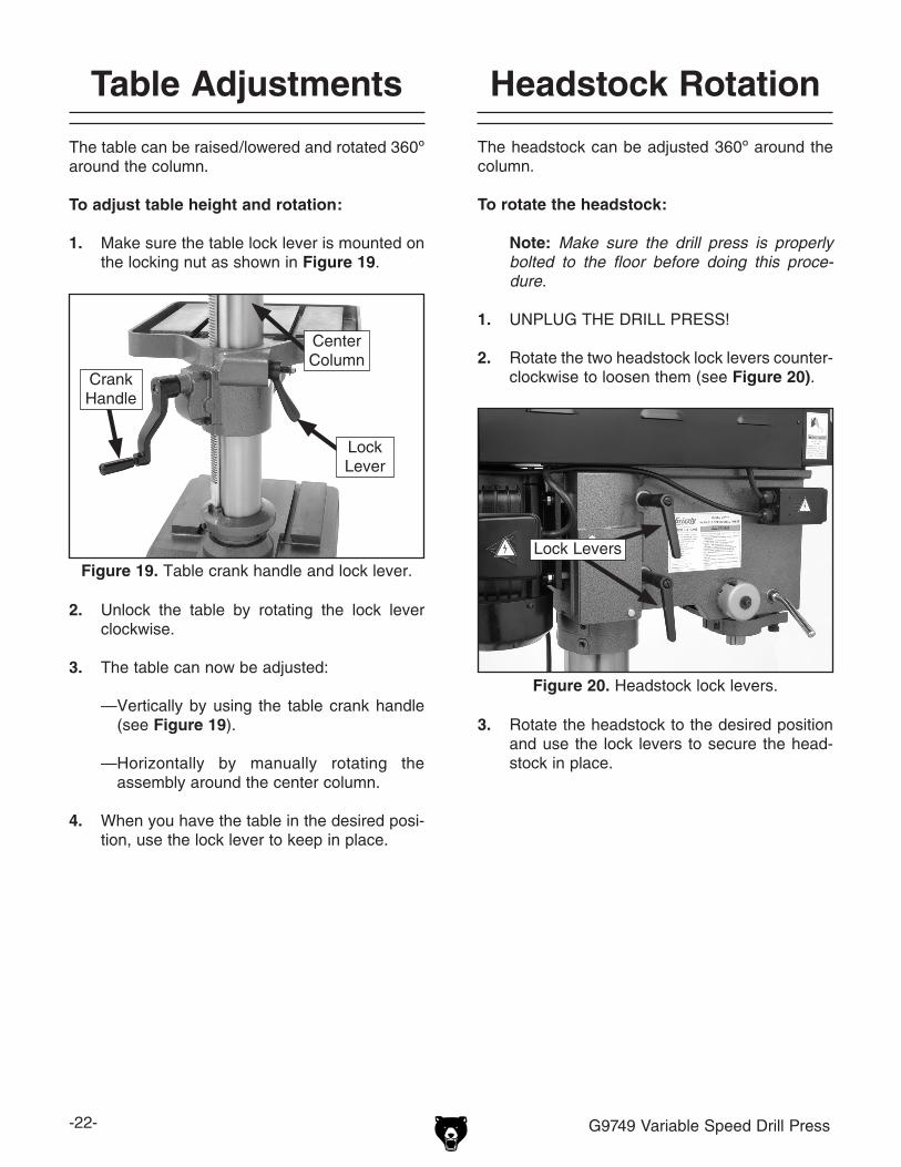
2. Unlock the table by rotating the lock lever clockwise.
3. The table can now be adjusted:
— Vertically by using the table crank handle (see Figure 19).
— Horizontally by manually rotating the assembly around the center column.
4. When you have the table in the desired posi-tion, use the lock lever to keep in place.
Table Adjustments
The table can be raised/lowered and rotated 360º around the column.
To adjust table height and rotation:
1. Make sure the table lock lever is mounted on the locking nut as shown in Figure 19.
The headstock can be adjusted 360º around the column.
To rotate the headstock:
Note: Make sure the drill press is properly bolted to the floor before doing this proce-dure.
1. UNPLUG THE DRILL PRESS!
2. Rotate the two headstock lock levers counter-clockwise to loosen them (see Figure 20).
3. Rotate the headstock to the desired position and use the lock levers to secure the head-stock in place.
Headstock Rotation
Figure 19. Table crank handle and lock lever.
Center Column
Lock Lever
Crank Handle
Figure 20. Headstock lock levers.
Lock Levers

G9749 Variable Speed Drill Press -23-
Removing/Installing Arbor and Chuck
Use the drawbar included with the Model G9749 to connect the included drill chuck arbor.
To remove the arbor and chuck from the spindle:
1. UNPLUG THE DRILL PRESS!
2. Use a 3mm hex wrench to remove the belt housing cover (see Figure 21).
3. Raise the quill to the highest position, and hold it place by tightening the quill lock lever.
4. Use a 17mm wrench to unscrew the drawbar 2–3 full turns without removing the threads from the arbor (see Figure 22).
5. Using a brass hammer or rubber mallet, strike the drawbar from the top, as shown in Figure 22, with a firm blow until the arbor releases from the spindle.
6. While holding the arbor and chuck with one hand, unthread the drawbar completely from the arbor.
Figure 21. Belt housing cover.
DO NOT operate the drill press when the belt housing cover is open. The movement of the belts and pulleys inside the headstock may entangle hands or clothes causing serious personal injury.
Figure 22. Tapping top of drawbar.
Belt Housing Cover
Quill Lock Lever
Drawbar
-24- G9749 Variable Speed Drill Press
To remove the chuck from the arbor:
1. UNPLUG THE DRILL PRESS!
2. Turn the chuck and arbor assembly upside down.
3. Retract the jaws of the chuck completely inside the chuck.
4. To avoid scratching the mating surface of the arbor, support the chuck in a way that leaves the arbor free from any contact with other objects.
5. Insert an appropriate tool inside the chuck so that it makes firm contact with the end of the arbor.
6. Hold the arbor with one hand and firmly strike the inserted tool with a hammer until the arbor releases from the chuck.
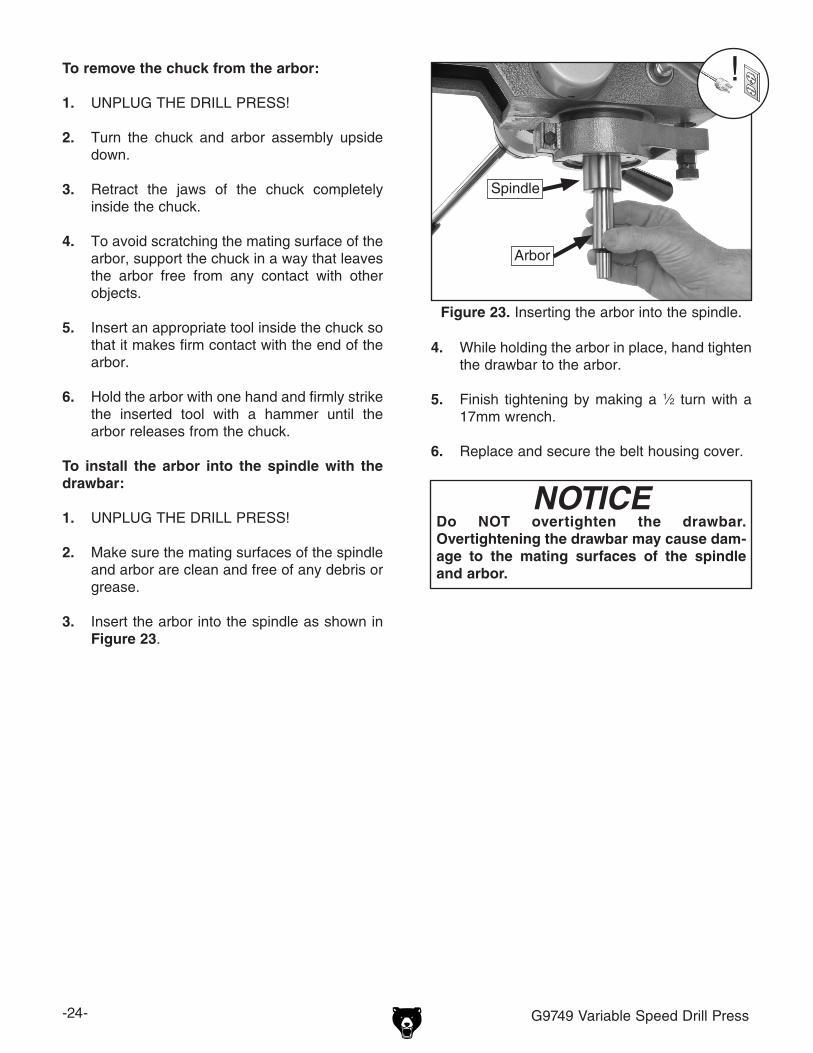
To install the arbor into the spindle with the drawbar:
1. UNPLUG THE DRILL PRESS!
2. Make sure the mating surfaces of the spindle and arbor are clean and free of any debris or grease.
3. Insert the arbor into the spindle as shown in Figure 23.
4. While holding the arbor in place, hand tighten the drawbar to the arbor.
5. Finish tightening by making a 1⁄2 turn with a 17mm wrench.
6. Replace and secure the belt housing cover.
Figure 23. Inserting the arbor into the spindle.
Spindle
Arbor
NOTICEDo NOT overtighten the drawbar. Overtightening the drawbar may cause dam-age to the mating surfaces of the spindle and arbor.

G9749 Variable Speed Drill Press -25-
SECTION 5: ACCESSORIESG2500—20-PC Regular Sanding Drum SetThis kit consists of 5 drums in popular 1⁄2" x 1⁄2", 3⁄4" x 1", 1"x 1", 11⁄2" x 11⁄2", and 2" x 11⁄2" sizes. Comes with 50, 80 and 120 grit sizes for each drum.
Figure 24. Model G2500 20-PC Sanding Drum Set.
G8865—Cobalt Alloy Drill Bits 13-PC. Set G8866—Steelex® Cobalt Alloy Drill Set 21-PCG8867—Steelex® Cobalt Alloy Drill Set 29-PCCobalt Alloy bits will retain their edge sharpness longer than normal HSS bits, resulting in a signifi-cant saving of time and money in the workshop. Includes a heavy-gauge steel index case for storing. G8865: 1⁄16" -1⁄4"; G8866: 1⁄16"- 3⁄8"; G8867: 1⁄16"-1⁄2".
Figure 25. Model G8865 13-PC Alloy Drill Bits.
H5685—4" Rotary TableThe perfect rotary table for all you model makers and those doing smaller precision work. Comes with clamping kit.
Figure 26. H5685 4" Rotary Table.
G1076—52-PC. Clamping KitThis clamping kit includes 24 studs, 6 step block pairs, 6 T-nuts, 6 flange nuts, 4 coupling nuts, and 6 end hold-downs. The rack is slotted so it can be mounted close to the machine for easy access.
Figure 27. G1076 52-PC. Clamping Kit.

-26- G9749 Variable Speed Drill Press
SECTION 6: MAINTENANCE
Always disconnect power to the machine before performing maintenance. Failure to do this may result in serious person-al injury.
Protect the unpainted cast iron surfaces on the table by removing vises and fixtures daily and by wiping the table clean after every use.
Keep tables rust-free with regular applications of products like G96® Gun Treatment or Boeshield® T-9. See below for Grizzly model numbers:
G2871—Boeshield® T-9 12 oz SprayG2870—Boeshield® T-9 4 oz SprayH3788—G96® Gun Treatment 12 oz SprayH3789—G96® Gun Treatment 4.5 oz Spray
Unpainted Cast Iron
For optimum performance from your machine, follow this maintenance schedule and refer to any specific instructions given in this section.
Daily Check:• Drill press is completely powered down at the
end of use.• Excess cutting fluids and chips have been
removed and unpainted surfaces are dry and protected.
• Floor mounting bolts are secure.• Drill press is clean and lubricated.• Examine wiring for damage or wear.• Check for any other unsafe condition.
Schedule
The quill and table use a rack and pinion assem-bly for movement. To ensure a smooth operation and a long life of these rack and pinion systems, lubricate as needed depending upon use.
Brush a small amount of multi-purpose grease on the rack near the pinion (see Figure 28 & 29). Move the table or quill up and down to distribute the grease.
Lubrication
Figure 28. Table rack lubrication point.
Note: All other bearings are lubricated and sealed at the factory, and do not need further lubrica-tion.
Figure 29. Quill rack lubrication point.

G9749 Variable Speed Drill Press -27-
This section is provided for your convenience—it is not a substitute for the Grizzly Service Department. If you need help troubleshooting, need replacement parts, or are unsure how to perform the procedures in this section, then feel free to call our Technical Support at (570) 546-9663.
SECTION 7: SERVICE
About Service
Symptom Possible Cause Possible SolutionMachine does not start or a breaker trips.
1. Plug or receptacle is at fault or wired incorrectly.
2. Cable or wiring is open or has high resistance.
3. Power supply is faulty, or is switched OFF.
4. Rotary switch at fault.5. Motor connection is wired incor-
rectly.6. Motor is at fault.
1. Test power plug and receptacle for good contact and correct wiring.
2. Troubleshoot wires for internal or external breaks, check for disconnected or corroded connections and repair or replace wiring, as necessary.
3. Make sure all hot lines and grounds are operational and have correct voltage on all legs.
4. Replace faulty switch.5. Correct motor wiring (see Wiring Diagram on Page
30).6. Test, repair or replace motor.
Machine stalls or is under-powered.
1. Incorrect drilling speed or feed rate.
2. Machine is undersized for the task.
3. Bit or cutter is too large for machine.
4. Belt is slipping.5. Plug or receptacle is at fault.
6. Pulley is slipping on shaft.7. Motor bearings are at fault.
8. Motor has overheated.
9. Motor connection is wired incor-rectly.
10. Motor is at fault.
1. Decrease drilling speed or feed rate.
2. Use smaller drill bits/cutters and reduce the feed rate and spindle speed.
3. Use a smaller bit or cutter.
4. Replace, realign, or re-tension belt.5. Test power plug and receptacle for good contact
and correct wiring.6. Replace loose pulley and shaft.7. Rotate motor shaft for noisy or burnt bearings,
repair/replace as required.8. Clean dust off motor, let it cool, and reduce work-
load on machine.9. Correct motor wiring (see Wiring Diagram on Page
30).10. Test, repair or replace motor.
Troubleshooting
Motor & Electrical
-28- G9749 Variable Speed Drill Press
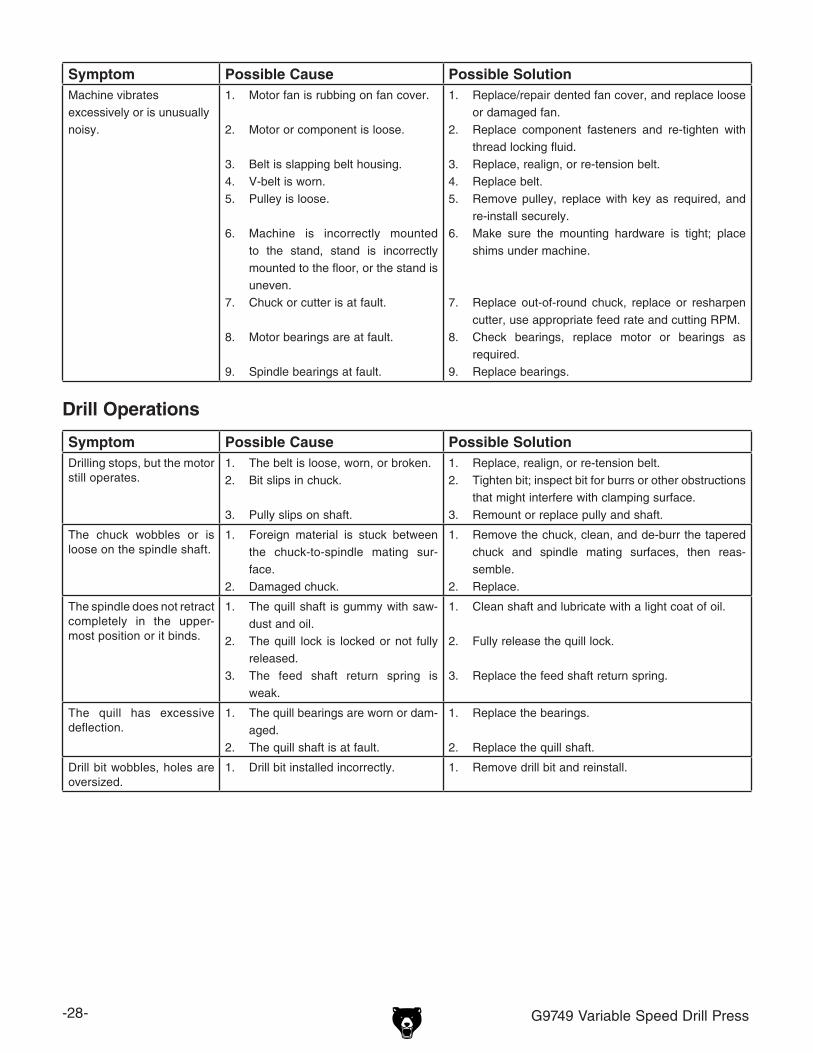
Symptom Possible Cause Possible SolutionMachine vibrates excessively or is unusually noisy.
1. Motor fan is rubbing on fan cover.
2. Motor or component is loose.
3. Belt is slapping belt housing.4. V-belt is worn.5. Pulley is loose.
6. Machine is incorrectly mounted to the stand, stand is incorrectly mounted to the floor, or the stand is uneven.
7. Chuck or cutter is at fault.
8. Motor bearings are at fault.
9. Spindle bearings at fault.
1. Replace/repair dented fan cover, and replace loose or damaged fan.
2. Replace component fasteners and re-tighten with thread locking fluid.
3. Replace, realign, or re-tension belt.4. Replace belt.5. Remove pulley, replace with key as required, and
re-install securely.6. Make sure the mounting hardware is tight; place
shims under machine.
7. Replace out-of-round chuck, replace or resharpen cutter, use appropriate feed rate and cutting RPM.
8. Check bearings, replace motor or bearings as required.
9. Replace bearings.
Symptom Possible Cause Possible SolutionDrilling stops, but the motor still operates.
1. The belt is loose, worn, or broken.2. Bit slips in chuck.
3. Pully slips on shaft.
1. Replace, realign, or re-tension belt.2. Tighten bit; inspect bit for burrs or other obstructions
that might interfere with clamping surface.3. Remount or replace pully and shaft.
The chuck wobbles or is loose on the spindle shaft.
1. Foreign material is stuck between the chuck-to-spindle mating sur-face.
2. Damaged chuck.
1. Remove the chuck, clean, and de-burr the tapered chuck and spindle mating surfaces, then reas-semble.
2. Replace.
The spindle does not retract completely in the upper-most position or it binds.
1. The quill shaft is gummy with saw-dust and oil.
2. The quill lock is locked or not fully released.
3. The feed shaft return spring is weak.
1. Clean shaft and lubricate with a light coat of oil.
2. Fully release the quill lock.
3. Replace the feed shaft return spring.
The quill has excessive deflection.
1. The quill bearings are worn or dam-aged.
2. The quill shaft is at fault.
1. Replace the bearings.
2. Replace the quill shaft.
Drill bit wobbles, holes are oversized.
1. Drill bit installed incorrectly. 1. Remove drill bit and reinstall.
Drill Operations

G9749 Variable Speed Drill Press -29-
Electrical Components
Figure 30. G9749 switch wiring. Figure 32. G9749 motor capacitors.
Figure 31. G9749 motor wiring (220V).
6
4
1
2
53

-30- G9749 Variable Speed Drill Press
Wiring Diagram���������
��
��
��
�������
�����
�����
���
���
���
���
�������
������
������
������
��������������������������
�������������������������
��������������
��
��
��
��
��
��
������������
������������
� �
������
������
����
��
��
������
��
� � � ���������
�����������
�������������������������������
���������������������
��
��
��
��
���������������������������������������������������������������
��
���
������
���
������
��
��
��
��
��
����
��
� � � � � �
������������
����������
�������������������������������
���������������������
��
��
��
��
��
������
��
�� ��
� � �
��
��
�� ��
� ��
����
�� ��

G9749 Variable Speed Drill Press -31-
Headstock Parts Breakdown
�
�
���� ��
��
��
���� ��
��
����
��
��
��
����
��
��
���
���
����
��
��
������
���
���
���
���
���
���
���
���
���
��
��
�����
���
��� ������
��
��
����
��
���
��� ��
���
��
��
��
��
����
���� ��
��� ��
����
��
����
���
���
���
���
���
���
���
���
���
���
������
��
��
���
�
Headstock Parts
Page 32
Page 32
Page 32
Page 32

-32- G9749 Variable Speed Drill Press
Headstock Components Parts Breakdown
�
�
�
���
�
�
�
�
����
����
����
������������
��
�����
�����
�����
�����
�����
���
���
���
���
���
���
������
���
���
���
���
�
�
�
�
����
���� ����
����
����
����
����
�� �
�����
�����
�����
����������
��� �
Headstock Component Parts
Page 31
Page 31
Page 31
Page 31
Page 33
Page 33
G9749 Variable Speed Drill Press -33-
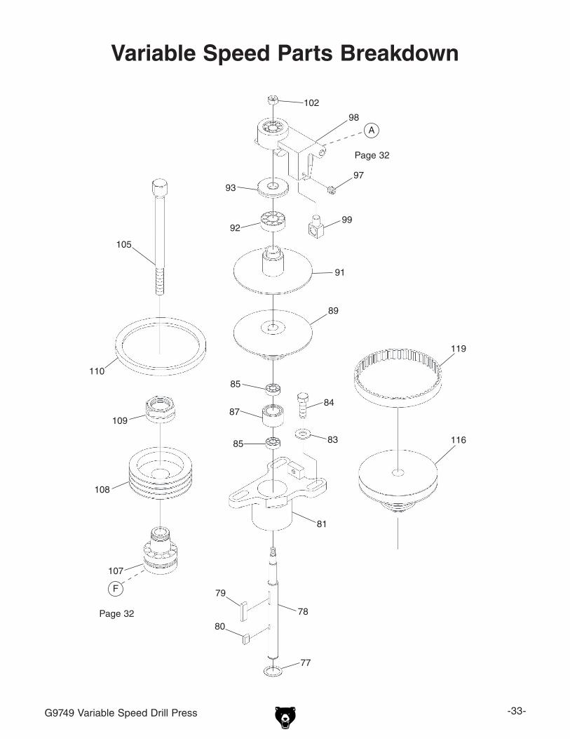
Variable Speed Parts Breakdown
�
���
���
���
���
���
��
��
��
��
���
��
��
��
��
��
��
��
��
��
��
���
��
��
���
���
�
VS Parts
Page 32
Page 32

-34- G9749 Variable Speed Drill Press
Base Parts Breakdown
���
���
������
������
���
���
���
���
������
���
���
���
���
���
���
���
���
������
���
���
���
���
���
���
���
���
���
���
���
���
���
���
���
������
���
���

G9749 Variable Speed Drill Press -35-
Parts ListREF PART # DESCRIPTION REF PART # DESCRIPTION
1 P9749001 HEAD BODY 55-2 P9749055-2 START CAP 400MFD 125VAC
2 P9749002 SPINDLE COVER 55-3 P9749055-3 CAPACITOR COVER
3 P9749003 BEARING NUT 55-4 P9749055-4 MOTOR FAN
4 P6206 BALL BEARING 6206ZZ 55-5 P9749055-5 MOTOR FAN COVER
5 P9749005 QUILL ASSEMBLY 55-6 P9749055-6 MOTOR JUNCTION BOX
6 P30207 TAPERED ROLLER BEARING 30207 55-7 P9749055-7 POWER SWITCH
7 P9749007 SPINDLE SHAFT 56 PB09 HEX BOLT 5/16-18 X 1/2
8 P9749008 BEARING WASHER 57 PW07 FLAT WASHER 5/16
9 P9749009 BEARING CAP 58 PSS06 SET SCREW 1/4-20 X 3/4
10 P9749010 PINION SUPPORT 74 P9749074 SPINDLE COVER
11 P9749011 PINION SHAFT 75 PB09 HEX BOLT 5/16-18 X 1/2
13 P9749013 MT3 3/8-16 CHUCK ARBOR 77 PR11M EXT RETAINING RING 25MM
14 P9749014 HANDLE ROD 78 P9749078 SHAFT
15 P9749015 HANDLE KNOB 79 P9749079 KEY 5 X 10 X 38
16 PK25M KEY 7 X 7 X 20 80 PK06M KEY 5 X 5 X 10
17 PSB05 CAP SCREW 1/4-20 X 3/4 81 P9749081 BEARING HOUSING
18 P9749018 PIN 83 PW04 FLAT WASHER 7/16
19 PR62M EXT RETAINING RING 42MM 84 PB90 HEX BOLT 7/16-14 X 1-1/4
20 P9749020 HEAD COVER UPPER 85 P6205 BALL BEARING 6205ZZ
21 P9749021 HEAD COVER RIGHT 87 P9749087 SPACER RING
22 P9749022 RUBBER FLANGE 89 P9749089 LOWER VS PULLEY
23 P9749023 HEX BOLT 1/2-13 X 5 91 P9749091 UPPER VS PULLEY
24 P9749024 HEAD LOCK 92 P6207 BALL BEARING 6207ZZ
25 P9749025 FIXED TIGHT COLLAR 93 P9749093 BEARING CAP
26 P9749026 LOCK HANDLE 97 PSS17 SET SCREW 5/16-18 X 5/16
27 PS05M PHLP HD SCR M5-.8 x 8 98 P9749098 SPEED CONTROL ASSY
28 PW02M FLAT WASHER 5MM 98-1 P9749098-1 SPEED CONTROL HOUSING
29 P9749029 CAM SPRING 98-2 P9749098-2 SPEED CONTROL FORK
30 P9749030 HUB 98-3 P9749098-3 HINGE PIN
31 P9749031 HANDLE 98-4 PRP16M ROLL PIN 3 X 25
33 PS06 PHLP HD SCR 10-24 X 3/8 98-5 PR24M INT RETAINING RING 42MM
34 PRP03M ROLL PIN 5 X 20 98-6 P9749098-6 BALL BEARING 6302Z
35 P9749035 PLATE 99 P9749099 SUPPORT SWIVEL
36 P51101 THRUST BEARING 51101 102 PN10 HEX NUT 7/16-20
37 P9749037 SPEED CHART 105 P9749105 DRAWBAR MT3 3/8
38 P9749038 SPECIAL HEX BOLT 107 P9749107 SPINDLE TAPER ASSY
39 PS04 PHLP HD SCR 1/4-20 X 1/2 107-1 P9749107-1 SPINDLE TAPER SLEEVE
40 PS05M PHLP HD SCR M5-.8 x 8 107-2 P6009 BALL BEARING 6009ZZ
41 PW02M FLAT WASHER 5MM 107-3 P9749107-3 BEARING SPACER SLEEVE
42 PN09M HEX NUT M12-1.75 107-4 PR56M EXT RETAINING RING 45MM
43 PW06M FLAT WASHER 12MM 108 P9749108 SPINDLE PULLEY
44 PW04 FLAT WASHER 7/16 109 P9749109 SPINDLE LOCKNUT
45 PB90 HEX BOLT 7/16-14 X 1-1/4 110 PVA25 V-BELT A-25 4L250
49 P9749049 PUSH ROD TUBE 116 P9749116 UPPER MOTOR PULLEY
50 PN09 HEX NUT 5/8-18 119 P9749119 1926v-427 TIMING BELT
52 P9749052 PIVOT SHAFT 120 P9749120 SPRING BASE
53 PN08 HEX NUT 3/8-16 121 P9749121 SPRING ASSEMBLY
54 PW02 FLAT WASHER 3/8 123 P9749123 COTTER PIN 3 X 12
55 P9749055 1-1/2HP 110V/220V 1PH MOTOR 124 PS08 PHLP HD SCR 10-24 X 3/4
55-1 P9749055-1 CAPACITOR 50MFD 250VAC 125 PLW02 LOCK WASHER 1/4

-36- G9749 Variable Speed Drill Press
Parts ListREF PART # DESCRIPTION REF PART # DESCRIPTION
126 PW06 FLAT WASHER 1/4 269 PSS17 SET SCREW 5/16-18 X 5/16
128 PSB01 CAP SCREW 1/4-20 X 5/8 270 P9749270 HANDLE
129 P9749129 LOCKING PLATE 300 P9749300 FEED ASSEMBLY
130 P9749130 T-SCREW 5/16-18 X 1 300-1 P9749300-1 FEED HOUSING
131 PB02 HEX BOLT 1/4-20 X 5/8 300-2 P9749300-2 WORM SHAFT
132 PW07 FLAT WASHER 5/16 300-3 P6202 BALL BEARING 6202ZZ
133 PB11 HEX BOLT 5/16-18 X 1-1/2 300-4 PR05M EXT RETAINING RING 15MM
134 P9749134 SUPPORT 300-5 P9749300-5 BEARING SPACER
135 P9749135 DRIFT KEY 301 PSB07 CAP SCREW 5/16-18 X 3/4
179 P9749179 BUSHING 302 P9749302 TRANSMISSION GEAR
201 P9749201 BASE 303 P9749303 COMPRESSION SPRING
202 P9749202 BEARING COVER 304 P9749304 UP DOWN HANDLE
203 P9749203 SQUARE WORKING TABLE 305 P9749305 LOCK BOLT WITH KNOB
212 P9749212 STEEL BALL 310 P9749310 HAND WHEEL
213 P9749213 BEARING COVER 311 P9749311 WORM COVER
214 P9749214 SPECIAL SCREW 312 PSB02 CAP SCREW 10-24 X 3/8
215 PN02 HEX NUT 5/16-18 313 PSS04 SET SCREW 1/4-20 X 5/16
216 P9749216 COLUMN BASE 314 P9749314 ADJUSTING INDICATOR
217 P9749217 HEAD BODY BASE 315 PSS17 SET SCREW 5/16-18 X 5/16
218 P9749218 BUSHING 316 P9749316 FIXED TIGHT COLLAR
219 P9749219 SET SCREW 1/2-13 X 5/8 317 P9749317 FIXED TIGHT COLLAR
221 PRP82M ROLL PIN 5 X 38 318 P9749318 HANDLE ROD
222 P9749222 RACK 319 PW01 FLAT WASHER 1/2
223 P9749223 SPECIAL LOCK BOLT 501 P9749501 HEAD COVER LEFT
224 P9749224 LOCK BLOCK 502 PFH01 FLAT HD SCR 10-24 X 3/8
225 PW14 FLAT WASHER 5/8 503 P9749503 ELEVATION BASE
226 PN04 HEX NUT 5/8-11 504 PB06 HEX BOLT 5/16-18 X 2
227 P9749227 LEVER HANDLE 505 PN02 HEX NUT 5/16-18
228 PN08 HEX NUT 3/8-16 506 P9749506 ELEVATION SHAFT
229 PW02 FLAT WASHER 3/8 507 P9749507 ELEVATION NUT
231 P51103 THRUST BEARING 51103 508 P9749508 BUSHING
235 PN08 HEX NUT 3/8-16 509 P9749509 DEPTH INDICATOR BRACKET
237 P9749237 SET SCREW 1/2-13 x 5/8 510 P9749510 DEPTH SCALE
238 P9749238 U-BOLT 511 PS18 PHLP HD SCR 10-24 X 1/4
239 P9749239 FIXED BLOCK 512 P9749512 DEPTH INDICATOR
240 PN06 HEX NUT 1/2-12 513 PS18 PHLP HD SCR 10-24 X 1/4
242 P9749242 ELEVATION BRACKET 514 P9749514 CHUCK W/KEY
243 P9749243 TRANSMISSION GEAR 515 P9749515 BUSHING
244 P9749244 SHAFT 516 P9749516 FILTER
258 P9749258 HEAD HANDLE 517 P9749517 CAP SCREW 3/8-16 X 3-1/2
259 P9749259 WORM SHAFT 518 PW03M FLAT WASHER 6MM
265 PSB03 CAP SCREW 5/16-18 X 1 519 PSB68M CAP SCREW M6-1 X 8
266 PSS03 SET SCREW 1/4-20 X 3/8 520 P9749520 BUSHING
268 P9749268 BUSHING BRACKET 521 P9749521 QUILL HOUSING

G9749 Variable Speed Drill Press -37-
Label Placement
Safety labels warn about machine hazards and ways to prevent injury. The owner of this machine MUST maintain the original location and readability of the labels on the machine. If any label is removed or becomes unreadable, REPLACE that label before using the machine again. Contact Grizzly at (800) 523-4777 or www.grizzly.com to order new labels.
REF PART # DESCRIPTION REF PART # DESCRIPTION
400 P9749400 MACHINE ID LABEL 404 PLABEL-11 SAFETY GLASSES 2" X 3 5/16"
401 P9749401 READ MANUAL-HORIZONTAL 405 PLABEL-14 ELECTRICITY LABEL
402 P9749402 SPEED NOTICE LABEL 406 PLABEL-10 GRIZZLY NAME PLATE
403 P9749403 ENTANGLEMENT LABEL 407 PPAINT-1 GRIZZLY GREEN PAINT
400
405
405
401
403
406
404
402

-38- G9749 Variable Speed Drill Press
Grizzly Industrial, Inc. warrants every product it sells for a period of 1 year to the original purchaser from the date of purchase. This warranty does not apply to defects due directly or indirectly to misuse, abuse, negligence, accidents, repairs or alterations or lack of maintenance. This is Grizzly’s sole written warranty and any and all warranties that may be implied by law, including any merchantability or fitness, for any par-ticular purpose, are hereby limited to the duration of this written warranty. We do not warrant or represent that the merchandise complies with the provisions of any law or acts unless the manufacturer so warrants. In no event shall Grizzly’s liability under this warranty exceed the purchase price paid for the product and any legal actions brought against Grizzly shall be tried in the State of Washington, County of Whatcom.
We shall in no event be liable for death, injuries to persons or property or for incidental, contingent, special, or consequential damages arising from the use of our products.
To take advantage of this warranty, contact us by mail or phone and give us all the details. We will then issue you a “Return Number,’’ which must be clearly posted on the outside as well as the inside of the carton. We will not accept any item back without this number. Proof of purchase must accompany the merchandise.
The manufacturers reserve the right to change specifications at any time because they constantly strive to achieve better quality equipment. We make every effort to ensure that our products meet high quality and durability standards and we hope you never need to use this warranty.
Please feel free to write or call us if you have any questions about the machine or the manual.
Thank you again for your business and continued support. We hope to serve you again soon.
WARRANTY AND RETURNS

�������
��������������
���������������������������������������������������������������������������������� �
������������������������������������������������������������������������������������
����� ����������������������� ������������������������������� ���� ���������������������
���������������������������� ������ ������������������������ ���������������������������
���������������������������� ������������������������������� ���������������������������
�������������
�����������������������������������������������������������������������������������������������������������������������������������������������������������������������������������������������������
��� ���������������������������� ����� �������������� � ���� ������� ����� �������� ����� ���������� � ������������ ����� ������
��� �����������������������������������������������������
��� �������������������������������������� ����� ���������������� � ���� ���������������� ����� ���������������� ����� ���������������� � ���� ���������������� ����� ��������
��� ������������������������ ����� ������ � ���� ������ ����� ������ ����� ������ � ���� ������ ����� ���
��� ������������������������������������������������� ����� ���������� ����� ���������� ����� ������������ � �������������
��� ������������������������������������������������ ����� ���� ����� ���� ����� ���� � �������
��� ��������������������������������������������������� ���������� ��������
��� ���������������������������������������������������� ���������� ��������
��� ��������������������������������������������������������������������������������������� �������������������������������������������� ���������� ��������
���� �������������������������������������������������������������������������������
� ����������������������������������������������������������������������������������
� ����������������������������������������������������������������������������������
� ����������������������������������������������������������������������������������
���� ����������������� ������������������� ��������������� ��������� ����������������������� �������������������������� �������������� ����������������������� ������������ �����������������
���� ��������������������� ������������������� ����������������������� ����������������������� ��������������������� ��������������������� �������������� �������� �������������� ������������
���� ��������������������� �������� ��������������� ����������������� ������������� ������������ ������������������� ������������������������ ������

��������������������������������������
����������������������
����������������������
���������������������������������������������������������������
��������������
�����������������������������������
�������������������������������������
��������������������������������������
�����������������������������������


�����������������������������������������������������������������������
����
�����������������
��������������������������������
���������������������������������
�������������������������������������������������������������������������
���������������������������������������