Embed Size (px)
Citation preview

Owner's Manual
IP R O F E S S I O H AL _
Variable Speed / ReversiblePROFESSIONAL 3/8 in.CORDLESS DRILL-DRIVER
Model No.973.271830
Save this manual forfuture reference
CAUTION: Read and follow all
Safety Rules and Operating Instructionsbefore first use of this product.
Customer Help Line: 1-800-932-3188
Sears, Roebuck and Co., Hoffman Estates, IL 60179 USA
Visit the Craftsman web page: www.sears.com/craftsman
972000-7452-00
• Safety• Features
• Operation• Maintenance• Parts List
US
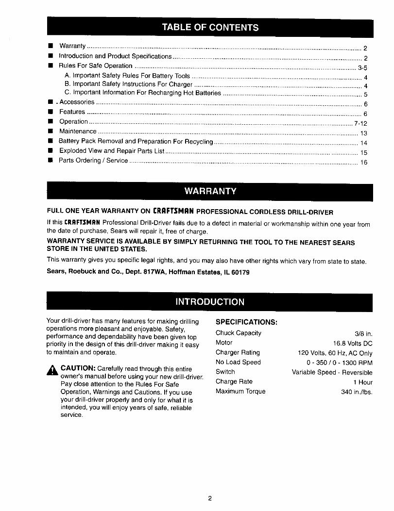
• Warranty ......................................................................................................................................................... 2
• Introduction and Product Specifications ......................................................................................................... 2
• Rules For Safe Operation ........................................................................................................................... 3-5
A. Important Safety Rules For Battery Tools .............................................................................................. 4B. Important Safety Instructions For Charger ............................................................................................. 4C. Important Information For Recharging Hot Batteries ............................................................................. 5
• oAccessories ....................................................................................................................................................
• Features ......................................................................................................................................................... 6
• Operation ................................................................................................................................................... 7-12
• Maintenance ................................................................................................................................................. 13
• Battery Pack Removal and Preparation For Recycling ................................................................................ 14
• Exploded View and Repair Parts List ........................................................................................................... 15
• Parts Ordering / Service ............................................................................................................................... 16
FULL ONE YEAR WARRANTY ON rRRFTSMRN PROFESSIONAL CORDLESS DRILL-DRIVER
If this rRRFTSMRN Professional Drill-Driver fails due to a defect in material or workmanship within one year fromthe date of purchase, Sears will repair it, free of charge.
WARRANTY SERVICE IS AVAILABLE BY SIMPLY RETURNING THE TOOL TO THE NEAREST SEARSSTORE IN THE UNITED STATES.
This warranty gives you specific legal rights, and you may also have other rights which vary from state to state.
Sears, Roebuck and COo,Dept. 817WA, Hoffman Estates, IL 60179
Your drill-driver has many features for making drillingoperations more pleasant and enjoyable. Safety,performance and dependability have been given toppriority in the design of this drill-driver making it easyto maintain and operate.
,_ CAUTION: Carefully read through this entireowner's manual before using your new drill-driver.Pay close attention to the Rules For SafeOperation, Warnings and Cautions. If you useyour drill-driver properly and only for what it isintended, you will enjoy years of safe, reliableservice.
SPECIFICATIONS:
Chuck CapacityMotor
Charger Rating
No Load SpeedSwitch
Charge Rate
Maximum Torque
3/8 in.
16.8 Volts DC
120 Volts, 60 Hz, AC Only
0- 350/0- 1300 RPM
Variable Speed - Reversible
1 Hour
340 in./Ibs.
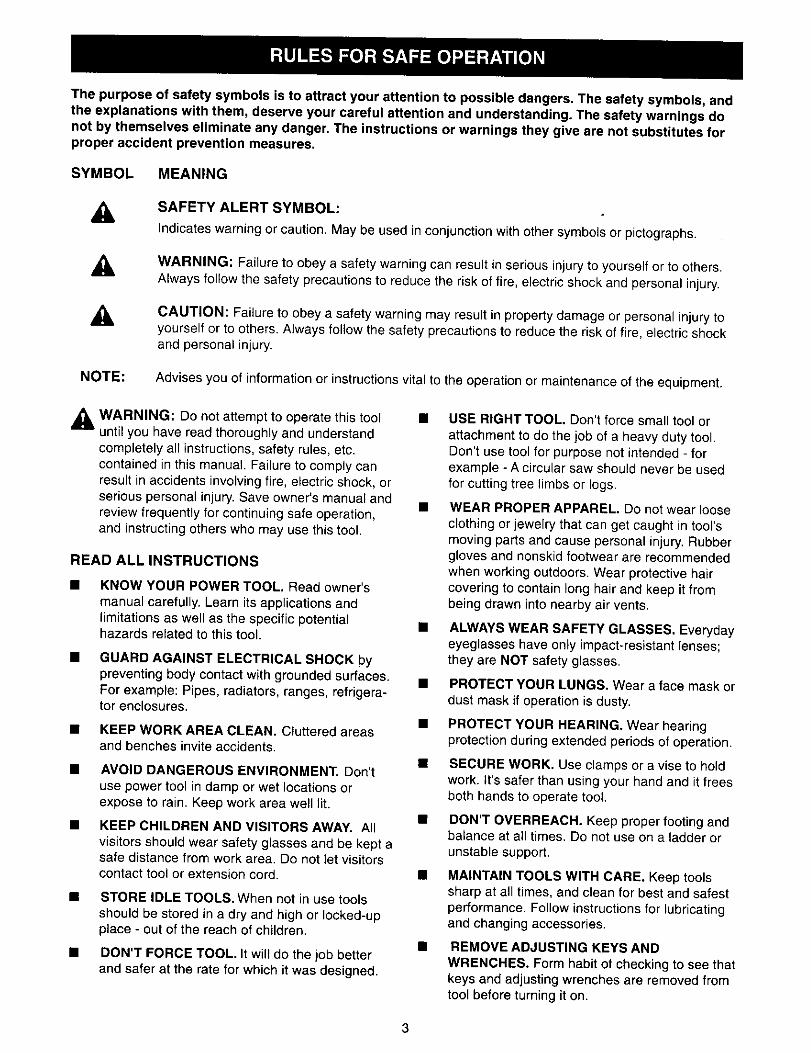
The purpose of safety symbols is to attract your attention to possible dangers. The safety symbols, andthe explanations with them, deserve your careful attention and understanding. The safety warnings donot by themselves eliminate any danger. The instructions or warnings they give are not substitutes forproper accident prevention measures.
SYMBOL MEANING
A SAFETY ALERT SYMBOL:
indicates warning or caution. May be used in conjunction with other symbols or pictographs.
A WARNING: Failure to obey a safety warning can result in serious injury to yourself or to others.Always follow the safety precautions to reduce the risk of fire, electric shock and personal injury.
A CAUTION: Fai{ure to obey a safety warning may result in property damage or personal injury toyourself or to ethers. Always follow the safety precautions to reduce the risk of fire, electric shockand personal injury.
NOTE: Advises you of information or instructions vital to the operation or maintenance of the equipment.
WARNING: Do not attempt to operate this tool •until you have read thoroughly and understandcomptetely all instructions, safety rules, etc.contained in this manual. Failure to comply canresult in accidents involving fire, electric shock, orserious personal injury. Save owner's manual andreview frequently for continuing safe operation,and instructing others who may use this tool.
READ ALL INSTRUCTIONS
KNOW YOUR POWER TOOL, Read owner's
manual carefully. Learn its applications andlimitations as well as the specific potentialhazards related to this tool.
GUARD AGAINST ELECTRICAL SHOCK bypreventing body contact with grounded surfaces.For example: Pipes, radiators, ranges, refrigera-tor enclosures.
• KEEP WORK AREA CLEAN. Cluttered areasand benches invite accidents.
• AVOID DANGEROUS ENVIRONMENT. Don't
use power tool in damp or wet locations orexpose to rain. Keep work area we_ltit.
KEEP CHILDREN AND VISITORS AWAY. Allvisitors should wear safety glasses and be kept asafe distance from work area. Do not let visitorscontact tool or extension cord,
• STORE IDLE TOOLS. When not in use toolsshould be stored in a dry and high or locked-upplace - out of the reach of children.
• DON'T FORCE TOOL. It will do the job betterand safer at the rate for which it was designed.
USE RIGHT TOOL. Don't force small tool or
attachment to do the job of a heavy duty tool.Don't use tool for purpose not intended - forexample - A circular saw should never be usedfor cutting tree limbs or logs.
WEAR PROPER APPAREL. Do not wear looseclothing or jewelry that can get caught in tool'smoving parts and cause personal injury. Rubbergloves and nonskid footwear are recommendedwhen working outdoors. Wear protective haircovering to contain long hair and keep it frombeing drawn into nearby air vents.
ALWAYS WEAR SAFETY GLASSES. Everydayeyeglasses have only impact-resistant lenses;they are NOT safety glasses.
PROTECT YOUR LUNGS. Wear a face mask or
dust mask if operation is dusty.
PROTECT YOUR HEARING. Wear hearingprotection during extended periods of operation.
SECURE WORK. Use clamps or a vise to holdwork. It's safer than using your hand and it freesboth hands to operate tool.
DON'T OVERREACH. Keep proper footing andbalance at all times. Do not use on a ladder orunstable support.
• MAINTAIN TOOLS WITH CARE. Keep toolssharp at all times, and clean for best and safestperformance. Follow instructions for lubricatingand changing accessories.
• REMOVE ADJUSTING KEYS ANDWRENCHES. Form habit ot checking to see thatkeys and adjusting wrenches are removed fromtool before turning it on.

RULES FOR SAFE OPERATION (Continued)
NEVER USE IN AN EXPLOSIVE ATMO-SPHERE. Normal sparking of the motor couldignite flammable liquids, gases, or fumes.
KEEP HANDLES DRY, CLEAN, AND FREEFROM OIL AND GREASE. Always use a cleancloth when cleaning. Never use brake fluids,gasoline, petroleum-based products or anystrong solvents to clean your tool.
STAY ALERT. Watch what you are doing anduse common sense. Do not operate tool whenyou are tired. Do not rush.
CHECK DAMAGED PARTS. Before further useof the tool, a guard or other part that is damagedshould be carefully checked to determine that itwill operate properly and perform its intendedfunction. Check for alignment of moving parts,binding of moving parts, breakage of parts,mounting, and any other conditions that mayaffect its operation. A guard or other part that isdamaged should be properly repaired orreplaced by an authorized service center unlessindicated elsewhere in this instruction manual.
• DO NOT USE TOOL IF SWITCH DOES NOTTURN IT ON AND OFF. Have defective switchesreplaced by an authorized service center.
• DRUGS, ALCOHOL, MEDICATION. Do notoperate tool while under the influence of drugs,alcohol, or any medication.
DRILLING OR DRIVING SCREWS INTOELECTRICAL WIRING IN WALLS, CEILINGS,OR OTHER AREAS CAN CAUSE THE BIT ORCHUCK TO BECOME ELECTRICALLY LIVE.Do not touch metal parts when drilling into a wall;grasp only the insulated handle(s) or plastichousing when using this tool. Make sure hiddenelectrical wiring, water pipes, and mechanicalhazards are not in the path of the bit whendrilling into a wall.
• INSPECT FOR and remove all nails from lumber
before drilling.
IMPORTANT SAFETY RULES FOR BATTERYTOOLS
Battery tools do not have to be plugged into anelectrical outlet; therefore, they are always inoperating condition. Be aware of possiblehazards when not using your battery tool orwhen changing accessories.
USE ONLY THE CHARGER PROVIDED WITH
YOUR BATTERY TOOL. Do not substitute anyother charger. Use of another charger couldcause batteries to explode causing possibleserious injury.
DO NOT PLACE BATTERY TOOLS OR THEIRBATTERIES NEAR FIRE OR HEAT. They mayexplode.
DO NOT CHARGE BATTERY TOOL IN ADAMP OR WET LOCATION.
Your battery tool should be charged in a locationwhere the temperature is more than 50°F butless than 100°F.
Under extreme usage or temperature conditions,battery leakage may occur. If liquid comes incontact with your skin, wash immediately withsoap and water, then neutralize with lemon juiceor vinegar. If liquid gets in your eyes, flush themwith clean water for at least 10 minutes, thenseek immediate medical attention.
If carrying your battery tool at your side, makesure it is not running and your finger is not on theswitch. Avoid accidental starting.
SECURE WORK before applying power. NEVERhold workpiece in your hand or across your legs.
WHEN SERVICING USE ONLY IDENTICALCRAFTSMAN REPLACEMENT PARTS.
IMPORTANT SAFETY INSTRUCTIONS FORCHARGER
SAVE THESE INSTRUCTIONS. This manual
contains important safety and operatinginstructions for battery charger item number_9-1f 039.
Before using battery charger, read all instructionsand cautionary markings in this manual, onbattery charger, and product using batterycharger.
,_ WARNING: To reduce risk of injury, charge onlynickel-cadmium type rechargeable batteries.Other types of batteries may burst causingpersonal injury and damage.
Do not expose charger to rain or snow.
Use of an attachment not recommended or sold
by the battery charger manufacturer may resultin a risk of fire, electric shock, or injury topersons.
To reduce risk of damage to charger body andcord, pull by charger body rather than cord whendisconnecting charger.
Make sure cord is located so that it will not bestepped on, tripped over, or otherwise subjectedto damage or stress.
4

RULES FOR SAFE OPERATION (Continued)
• An extension cord should not be used unless •absolutely necessary. Use of improperextension cord could result in a risk of fire andelectric shock. If extension cord must be used,make sure:
a. That pins on plug of extension cord are thesame number, size and shape as those ofplug on charger.
b. That extension cord is properly wired and ingood electrical condition; and
c. That wire size is large enough for ACampere rating of charger as specifiedbelow:
Cord Length (Feet) 25' 50' 100'
Cord Size (AWG) 16 16 16
Note: AWG = American Wire Gage
DO NOT OPERATE CHARGER WITH ADAMAGED CORD OR PLUG. If damaged,have replaced immediately by a qualifiedserviceman.
Do not operate charger if it has received asharp blow, been dropped, or otherwisedamaged in any way; take it to a qualifiedserviceman.
Do not disassemble charger; take it to aqualified serviceman when service or repair isrequired. Incorrect reassembly may result in arisk of electric shock or fire.
To reduce risk of electdc shock, unplug chargerfrom outlet before attempting any maintenanceor cleaning. Turning off controls will not reducethis risk.
Do not use charger outdoors.
Disconnect charger from power supply whennot in use.
SAVE THESE INSTRUCTIONS. Refer to themfrequently and use them to instruct others whomay use this tool. If you loan someone this tool,loan them these instructions also.
,_ Look for this symbol to point out important safety precautions. It means attention!H Yoursafety is involved.
IMPORTANT INFORMATION FOR RECHARGING HOT BATTERIES
When using your drill-driver continuously, the batteries in your battery pack will become hot. You should let a hotbattery pack cool down for approximately 30 minutes before attempting to recharge. When the battery packbecomes discharged and is hot, this will cause the yellow and green lights on your battery charger to come oninstead of the red light. The yellow and green lights indicate soft start mode and will switch to green only, indicat-ing slow charge mode. The red light indicates fast charge mode, 1 hour charge time. The green light indicatesslow charge mode, requiring overnight charging for batteries to reach full charge. If the green light comes onafter letting battery pack cool down, remove it from charger for additional cooling. Once the battery pack coolsdown, you can recharge battery pack in fast charge mode as normal. Do not leave a hot battery pack in chargeruntil it cools down. The green light will not go off when battery pack cools. If fast charge mode is desired, youmust physically remove a hot battery pack from the charger, let it cool, then place it back in charger after it hascooled down.
Note: This situation only occurs when continuous use of your drill causes the batteries to become hot. It doesnot occur under normal circumstances. Refer to "CHARGING YOUR DRILL-DRIVER" for normal recharging ofbatteries. If the charger does not charge your battery pack under normal circumstances, return both the batterypack and charger to your nearest Sears repair center for electrical check.
,_ WARNING:
The operation of any power tool can result in foreign objects being thrown into your eyes,which can result in severe eye damage. Before beginning power tool operation, alwayswear safety goggles or safety glasses with side shields and a full face shield when needed.We recommend Wide Vision Safety Mask for use over eyeglasses or standard safetyglasses with side shields, available at Sears Retail Stores.

Thefollowingrecommendedaccessoriesarecurrentlyavailableat SearsRetailStores.
• 6-Pc.ExtraLengthMagnitePowerBitSet • HighSpeedBits(ForWoodorMetal)..3/4in.Max.
• 30-Pc.PowerScrewdriver/NutdriverSetandCase • KeylessChuck(ItemNo.9-20988)• 17-Pc.PowerScrewdriver/NutdriverSetandCase
,_ WARNING: The use of attachments or accessories not listed might be hazardous.
KNOW YOUR DRILL-DRIVER
See Figure 1,
Before attempting to use any tool familiarize yourselfwith all operating features and safety requirements.
BATTERYPACK
WRIST STRAP
See Figure 1.
A wrist strap is provided to reduce the chances ofdropping your drill-driver. Place one hand through thewrist strap when carrying tool.
"flNO-SPEEDGEARTRAIN (HI-LO)
BIT STORAGE LEVEL
KEYLESSCHUCK
i MODE
SELECTOR
YELLOWAND GREENLIGHTSINDICATESOFTSTARTMODE
GREENLIGHT "ON"INDICATESSLOWCHARGINGMODEOR FULLYCHARGED
SWITCHTRIGGER
BATTERYCHARGER
WRIST STRAP
_ SCREWDRIVERBITS
Fig. 1
,_ WARNING: If any parts are missing, do not operate tool until the missing parts are replaced. Failure to doso could result in possible serious personal injury.

_ WARNING: Always wear safety goggles orsafety glasses with side shields when operatingtools. Failure to do so could result in objectsbeing thrown into your eyes, resulting in possibleserious injury.
,_ WARNING: Do not allow familiarity with yourdrill-driver to make you careless. Remember thata careless fraction of a second is sufficient toinflictsevere injury.
CHARGING YOUR DRILL-DRIVER
The battery pack for this tool has been shipped in alow charge condition to prevent possible problems.Therefore, you should charge it until light on front ofcharger changes from red to green.
Note: Batteries will not reach full charge the first timethey are charged. Allow several cycles (drillingfollowed by recharging) for them to become fullycharged.
TO CHARGE
• Charge battery pack only with the chargerprovided.
• Make sure power supply is normal householdvoltage, 120 volts, 60 Hz, AC only.
• Connect charger to power supply.
• Place battery pack in charger aligning raised rib incharger with groove in battery pack.
• Press down on battery pack to be sure contacts onbattery pack engage properly with chargercontacts.
Normally, the yellow and green lights on chargerwill come on. This indicates charger is in soft startmode and should switch to fast charge mode within5 minutes. When charger is in fast charge modethe red light will come on. If after a period of 15minutes the yellow and green lights remain on,remove battery pack, wait 1 minute and reinsertbattery pack in charger. If the yellow and greenlights continue to remain on after an additional 15minutes, the battery pack is damaged and will notaccept a charge. Return battery pack to yournearest Sears Repair Center for checking orreplacing.
When your battery pack becomes fully charged, thered light will turn OFF and the green light will turnON.
• After normal usage, 1 hour of charging time isrequired to be fully charged. A minimum chargetime of 1-1/2 hours is required to recharge acompletely discharged tool.
• The battery pack will become slightly warm to thetouch while charging. This is normal and does notindicate a problem.
• Do not place charger in an area of extreme heat orcold. It will work best at normal room temperature,
• When batteries become fully charged, unplugcharger from power supply and remove the batterypack.
7

SWITCH
See Figure 2.
To turn your drill ON, depress the switch trigger. Toturn it OFF, release the switch trigger.
CENTERPOSITION L mJ(LOCK) _---'J ]
SE,ECTOR
Fig. 2
VARIABLE SPEED
This tool has a variable speed switch that delivers higherspeed and torque with increased trigger pressure. Speedis controlled by the amount of switch trigger depression.
Note: You might hear a whistling or ringing noise fromthe switch during use. Do not be concerned, this is anormal part of the switch function.
TWO-SPEED GEAR TRAINSee Figure 3.
Your drill has a two-speed gear train designed fordrilling or driving at HI or LO speeds. A slide switch islocated on top of your drill to select either HI or LOspeed. When using drill in the HI speed range, speedwill increase and unit will have less power and torque.When using drill in the LO speed range, speed willdecrease and unit will have more power and torque.Use HI speed for fast drilling or driving applicationsand LO speed for high power and torque applications.
HISPEED
LO SPEED TWOSPEED
GEARTRAIN(HI-LO)
TO INSTALL BATTERY PACK
• Lock switch trigger on your drill by placing thedirection of rotation selector in center position.See Figure 2.
• Place battery pack in your drill. Align raised ribinside drill with groove on battery pack.See Figure 4.
BATTERYPACK
LATCHES
DEPRESSLATCHESTORELEASEBATTERYPACK Fig. 4
• Make sure the latches on each side of your batterypack snap in place and battery pack is secured indrill before beginning operation.
CAUTION: When placing battery pack in yourdrill, be sure raised rib inside drill aligns withgroove on battery pack and latches snap in placeproperly. Improper assembly of battery pack cancause damage to internal components.
TO REMOVE BATTERY PACK
• Lock switch trigger on your drill by p_acing thedirection of rotation selector in center position.See Figure 2.
• Locate latches on end of battery pack and depressto release battery pack from your drill.See Figure 4.
• Remove battery pack from your drill.
Fig. 3
8
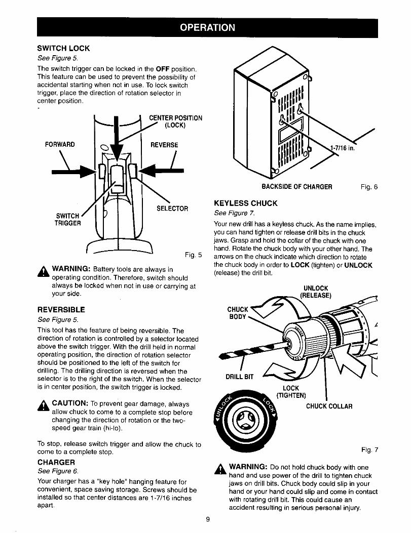
SWITCH LOCK
See Figure 5.
The switch trigger can be locked in the OFF position.This feature can be used to prevent the possibility ofaccidental starting when not in use. To lock switchtrigger, place the direction of rotation selector incenter position.
CENTER POSITION(LOCK)
FORWARD REVERSE -7/16 in.
TRIGGER
SELECTOR
Fig. 5
WARNING: Battery tools are always inoperating condition. Therefore, switch shouldalways be looked when not in use or carrying atyour side.
REVERSIBLE
See Figure 5.
This tool has the feature of being reversible. Thedirection of rotation is controlled by a selector locatedabove the switch trigger. With the drill held in normaloperating position, the direction of rotation selectorshould be positioned to the left of the switch fordrilling. The drilling direction is reversed when theselector is to the right of the switch. When the selectoris in center position, the switch trigger is locked.
,_1 CAUTION: To prevent gear damage, alwaysallow chuck to come to a complete stop beforechanging the direction of rotation or the two-speed gear train (hi-lo).
To stop, release switch trigger and allow the chuck tocome to a complete stop.
CHARGER
See Figure 6.
Your charger has a "key hole" hanging feature forconvenient, space saving storage. Screws should beinstalled so that center distances are 1-7/16 inchesapart.
BACKSIDEOF CHARGER Fig. 6
KEYLESS CHUCK
See Figure
Your new drill has a keyless chuck. As the name implies,you can hand tighten or release drill bits in the chuckjaws. Grasp and hold the collar of the chuck with onehand. Rotate the chuck body with your other hand. Thearrows on the chuck indicate which direction to rotatethe chuck body in order to LOCK (tighten) or UNLOCK(release) the drill bit.
UNLOCKRELEASE)
CHUCKBODY
DRILLBIT
LOCK
(TIGHTEN) COLLAR
CHUCK
Fig. 7
_i WARNING: Do not hold chuck body with onehand and use power of the drill to tighten chuckjaws on drill bits. Chuck body could slip in yourhand or your hand could slip and come in contactwith rotating ddll bit. This could cause anaccident resulting in serious personal injury.
9
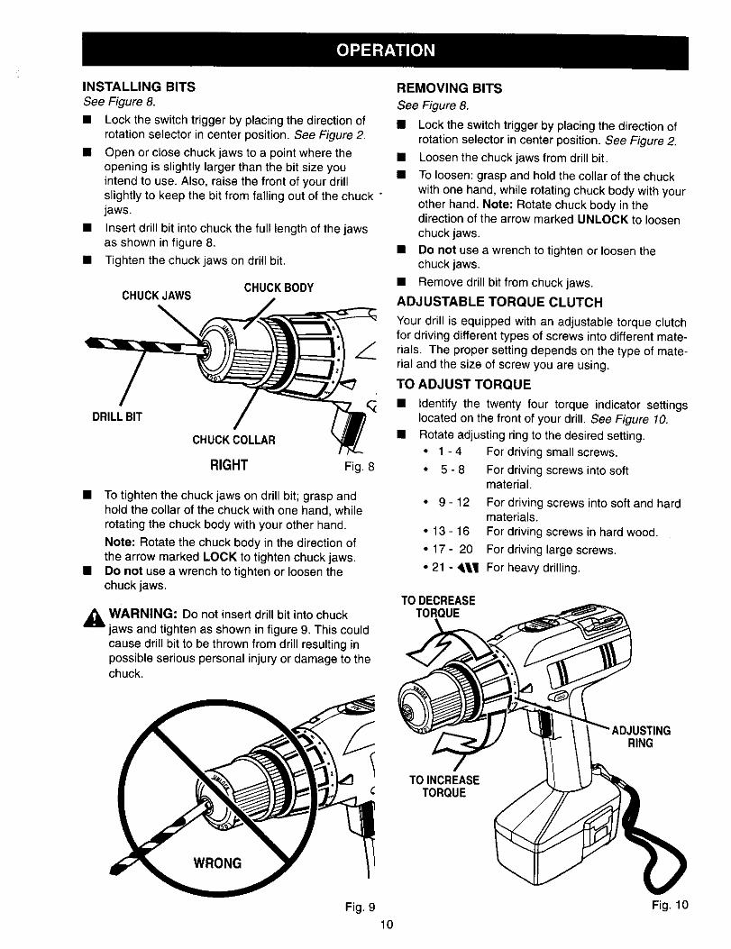
INSTALLING BITS
See Figure 8.
Lock the switch trigger by placing the direction ofrotation selector in center position. See Figure 2.
Open or close chuck jaws to a point where theopening is slightly larger than the bit size youintend to use. Also, raise the front of your drillslightly to keep the bit from falling out of the chuck "jaws.
• Insert drill bit into chuck the full length of the jawsas shown in figure 8.
• Tighten the chuck jaws on drill bit.
CHUCKJAWSCHUCKBODY
DRILL BIT
CHUCKCOLLAR
RIGHT Fig. 8
• To tighten the chuck jaws on drill bit; grasp andhold the collar of the chuck with one hand. whilerotating the chuck body with your other hand.
Note: Rotate the chuck body in the direction ofthe arrow marked LOCK to tighten chuck jaws.
• Do not use a wrench to tighten or loosen thechuck jaws.
,_L WARNING: Do not insert drill bit into chuckjaws and tighten as shown in figure 9. This couldcause drill bit to be thrown from drill resulting inpossible serious personal injury or damage to thechuck.
REMOVING BITS
See Figure 8.
• Lock the switch trigger by placing the direction ofrotation selector in center position. See Figure 2.
• Loosen the chuck jaws from drill bit.
• To loosen: grasp and hold the collar of the chuckwith one hand, while rotating chuck body with yourother hand. Note: Rotate chuck body in thedirection of the arrow marked UNLOCK to loosenchuck jaws.
• Do not use a wrench to tighten or loosen thechuck jaws.
• Remove drill bit from chuck jaws.
ADJUSTABLE TORQUE CLUTCH
Your drill is equipped with an adjustable torque clutchfor driving different types of screws into different mate-rials. The proper setting depends on the type of mate-rial and the size of screw you are using.
TO ADJUST TORQUE
• Identify the twenty four torque indicator settingslocated on the front of your drill. See Figure 10.
• Rotate adjusting ring to the desired setting.
• 1 - 4 For driving small screws.
• 5 - 8 For driving screws into softmaterial.
• 9 - 12 For driving screws into soft and hardmaterials.
• 13 - 16 For driving screws in hard wood.
• 17 - 20 For driving large screws.
• 21 - ,l¶ For heavy drilling.
TO DECREASETORQUE
TOINCREASETORQUE
RING
Fig. 9 Fig. 10
10

Note: Remember the two-speed feature (HI-LO) whensetting torque. The amount of torque will vary depend-ing on which speed setting you have your drill-driver.Switching to LO speed will increase torque. Switchingto HI speed will decrease torque.
BIT STORAGESee Figure 11.
When not in use, bits provided with your drill can beplaced in the storage area located on the top of yourdrill as shown in figure 11.
SCREWDRIVERBITS
DRILLING
See Figure 13.
BIT STORAGEAREAFig. 11
,_ WARNING: Always wear safety goggles orsafety glasses with side shields when operatingtools. Failure to do so could result in objectsbeing thrown into your eyes, resulting in possibleserious injury.
LEVEL DRILLING
See Figure 12.
A convenient new feature provided with your drill is alevel, It is recessed in the motor housing on top ofyour drill. It can be used to keep drill bits level duringdrilling operations.
Fig. 12
Fig. 13
When drilling hard smooth surfaces use a centerpunch to mark desired hole location. This will preventthe drill bit from slipping off center as the hole isstarted. However, the low speed feature allowsstarting holes without center punching if desired. Toaccomplish this, simply operate your drill at a lowspeed until the hole is started.
The material to be drilled should be secured in a viseor with clamps to keep it from turning as the drill bitrotates.
Hold tool firmly and place the bit at the point to bedrilled. Depress the switch trigger to start tool.
Move the drill bit into the workpiece applying onlyenough pressure to keep the bit cutting. Do not forceor apply side pressure to elongate a hole.
_i WARNING: Be prepared for binding or bitbreakthrough. When these situations occur, drillhas a tendency to grab and kick opposite to thedirection of rotation and could cause loss of
control when breaking through material, if notprepared, this loss of control can result inpossible serious injury.
When drilling metals, use a light oil on the drill bit tokeep it from overheating. The oil will prolong the life ofthe bit and increase the drilling action.
If the bit jams in workpiece or if the drill stalls, releaseswitch trigger immediately. Remove the bit from theworkpiece and determine the reason for jamming.
11

CHUCK REMOVAL
See Figures 14, 15, and 16.
The chuck must be removed in order to use someaccessories. To remove:
• Lock the switch trigger by placing the direction ofrotation selector in center position.
• Insert a 5/16 inch or larger hex key wrench into thechuck of your drilland tighten the chuck jawssecurely.
• Tap the hex key wrench sharply with e mallet in ac_ockwise direction, See Figure 14. This willloosen the screw in the chuck for easy removal.
MALLET
KEYLESSCHUCK
CHUCKJAWS HEX KEYWRENCH
Fig. 14
Open chuck jaws and remove wrench. Removethe chuck screw by turning it in a clockwisedirection. See Figure 15. Note: The screw has lefthand threads.
Insert hex key wrench in chuck and tighten chuckjaws securely. Tap sharply with a mallet in acounterclockwise direction. This will loosen chuckon the spindle. It can now be unscrewed by hand.See Figure 16.
Fig. 16
TO RETLGHTEN A LOOSE CHUCK
The chuck may become loose on spindle and developa wobble. Also, the chuck screw may become loosecausing the chuck jaws to bind and prevent them fromclosing. To tighten, follow these steps:
• Lock the switch trigger by placing the direction ofrotation selector in center position.
• Insert hex key wrench into chuck and tightenchuck jaws securely. Tap hex key wrench sharplywith a mallet in a clockwise direction. This willtighten chuck on the spindle.
• Open the chuck jaws and remove wrench.
• Tighten the chuck screw. Note: The chuck screwhas left hand threads.
Fig. 15
12

_k WARNING:Whenservicing,useonlyidenticalCraftsmanreplacementparts.Useof anyotherpart may create a hazard or cause productdamage.
Avoid using solvents when cleaning plastic parts.Most plastics are susceptible to damage from varioustypes of commercial solvents and may be damagedby their use. Use clean cloths to remove dirt, dust, oil,grease, etc.
,_ WARNING: Do not at any time let brake fluids,gasoline, petroleum-based products, penetratingoils, etc. come in contact with plastic parts. Theycontain chemicals that can damage, weaken ordestroy plastic.
Do not abuse power tools. Abusive practices candamage tool as well as workpiece.
Only the parts shown on parts list, page 15, areintended to be repaired or replaced by the customer.All other parts should be replaced by a qualifiedservice technician at an authorized service facility.
_k WARNING: Do not attempt to modify this tool orcreate accessories not recommended for usewith this tool. Any such alteration or modificationis misuse and could result in a hazardouscondition leading to possible serious personalinjury.
BATTERIES
Your drill's battery pack is equipped with 14 nickel-cadmium rechargeable batteries. Length of servicefrom each charging will depend on the type of workyou are doing.
The batteries in this tool have been designed toprovide maximum trouble free life. However, like allbatteries, they will eventually wear out. Do notdisassemble battery pack and attempt to replace thebatteries. Handling of these batteries, especially whenwearing rings and jewelry, could result in a seriousburn.
To obtain the longest possible battery life, we suggestthe following:
Store and charge your batteries in a cool area.Temperatures above normal room temperaturewill shorten battery life.
Never store batteries in a discharged condition.Recharge them immediately after they aredischarged.
All batteries gradually lose their charge. Thehigher the temperature the quicker they lose theircharge. If you store your tool for long periods oftime without using it, recharge the batteries everymonth or two. This practice will prolong batterylife.
OVERLOAD
Your drill has a built-in overload protector to protect the motor during overloading or prolonged use. Theoverload protector automatically activates to break the circuit. When this occurs, allow your drill to cool a fewseconds before resuming operation.
13

Topreservenaturalresources,pleaserecycleordisposeofproperly.Thisproductcontainsnickel-cadmiumbatteries.Local,stateorfederallawsmayprohibitdisposalofnickel-cadmiumbatteriesinordinarytrash.
Consultyourlocalwasteauthorityforinformationregardingavailablerecyclingand/ordisposaloptions.
BATTERY PACK REMOVAL ANDPREPARATION FOR RECYCLING
_lb WARNING: Upon removal, cover the batterypack's terminals with heavy duty adhesive tape.Do not attempt to destroy or disassemble batterypack or remove any of its components. Nickel-cadmium batteries must be recycled or disposedof properly. Also, never touch both terminals withmetal objects and/or body parts as short circuitmay result. Keep away from children. Failure tocomply with these warnings could result in fireand/or serious injury.
14

ICRAFTSMAN PROFESSIONAL 318 in. CORDLESS DRILL-DRIVER
MODEL NO, 973.271830
IThe model number will be found on a plate attached to the motor housing. Always mention the model |number inall correspondence regarding your 3/8 in. CORDLESS DRILL-DRIVER or when ordering Irepair pads,
SEE BACK PAGE FOR PARTS ORDERING INSTRUCTIONS
2
1
5
h'%wr-
Key Pa_No. Number
1 616478-003
2 973015-001
3 967216-004
4 *9-11038
5 * 9-11039
6 981888-001
972000-745
PARTS LIST
Description Quan.
Screw (Special) ................................................................. 1
Chuck (Item No. 9-20988) ................................................. 1
Wrist Strap ........................................................................ 1
Battery Pack (Includes Part Number 981886-001 ) ........... 1
Battery Charger (Includes Part Number 981887-001) ...... 1
Carrying Case - Not Shown .............................................. 1
Owner's Manual
* Can Be Purchased Thru RSOS (Retail Special Order System)
15

In U.S.A. or Canada
for in-home major brand repair service:
Call 24 hours a day, 7 days a week
1-800-4-MY-HOM E" (1-800-469-4663)
Para pedir servicio de reparacibn a domicilio - 1-800-676-5811
Au Canada pour tout le service ou les pieces - 1-800-469 4663
For the repair or replacement parts you need:
Call 6 a.m. - 11 p.m. CST, 7 days a week
Parts Direct s°
1-800-366-PART (1-800-366-7278)
Para ordenar piezas con entrega a domicilio - 1-800-659-7084
For the location of a Sears Service Center in your area:Call 24 hours a day, 7 days a week
1-800-488-1222
To purchase or inquire about a Sears Maintenance Agreement:Call 7 a.m. - 5 p.m. CST, Monday - Saturday
1-800-827-6655
r