Embed Size (px)
Citation preview
TECHNICAL BULLETIN
Model 1088Vacu-Gard® Tank Blanketing Valve
1/2” (DN15)
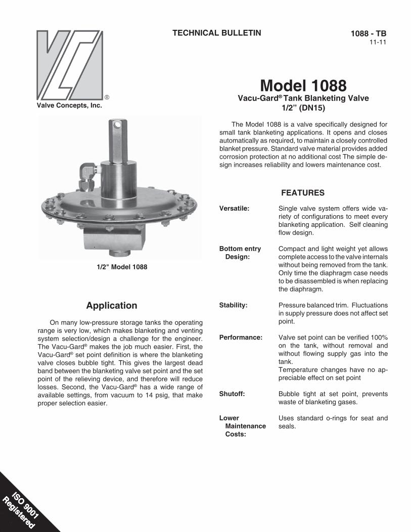
The Model 1088 is a valve specifi cally designed for small tank blanketing applications. It opens and closes automatically as required, to maintain a closely controlled blanket pressure. Standard valve material provides added corrosion protection at no additional cost The simple de-sign increases reliability and lowers maintenance cost.
1088 - TB11-11
1/2" Model 1088
Valve Concepts, Inc.
Application
On many low-pressure storage tanks the operating range is very low, which makes blanketing and venting system selection/design a challenge for the engineer. The Vacu-Gard® makes the job much easier. First, the Vacu-Gard® set point defi nition is where the blanketing valve closes bubble tight. This gives the largest dead band between the blanketing valve set point and the set point of the relieving device, and therefore will reduce losses. Second, the Vacu-Gard® has a wide range of available settings, from vacuum to 14 psig, that make proper selection easier.
Versatile:
Bottom entry Design:
Stability:
Performance:
Shutoff:
Lower Maintenance Costs:
Single valve system offers wide va-riety of confi gurations to meet every blanketing application. Self cleaning fl ow design.
Compact and light weight yet allows complete access to the valve internals without being removed from the tank. Only time the diaphragm case needs to be disassembled is when replacing the diaphragm.
Pressure balanced trim. Fluctuations in supply pressure does not affect set point.
Valve set point can be verifi ed 100% on the tank, without removal and without fl owing supply gas into the tank.Temperature changes have no ap-preciable effect on set point
Bubble tight at set point, prevents waste of blanketing gases.
Uses standard o-rings for seat and seals.
FEATURES
2 1088-TB
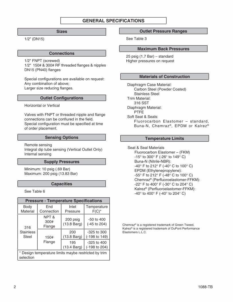
GENERAL SPECIFICATIONS
Sizes
1/2” (DN15)
Connections
1/2" FNPT (screwed) 1/2" 150# & 300# RF threaded fl anges & nipples DN15 (PN40) fl anges
Special confi gurations are available on request: Any combination of above; Larger size reducing fl anges.
Outlet Confi gurations
Horizontal or Vertical
Valves with FNPT or threaded nipple and fl ange connections can be confi ured in the fi eld. Special confi guration must be specifi ed at time of order placement.
Sensing Options
Remote sensing Integral dip tube sensing (Vertical Outlet Only) Internal sensing
Supply Pressures
Minimum: 10 psig (.69 Bar) Maximum: 200 psig (13.83 Bar)
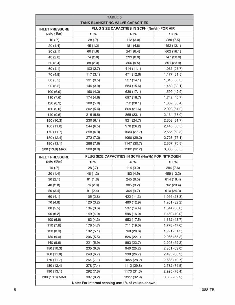
Capacities
See Table 6
Outlet Pressure Ranges
See Table 3
Maximum Back Pressures
25 psig (1.7 Bar) – standard Higher pressures on request
Materials of Construction
Diaphragm Case Material: Carbon Steel (Powder Coated) Stainless Steel Trim Material: 316 SST Diaphragm Material: PTFE Soft Seat & Seals: Fluorocarbon Elastomer – standard, Buna-N, Chemraz®, EPDM or Kalrez®
Temperature Limits
Seat & Seal Materials Fluorocarbon Elastomer – (FKM) -15° to 300° F (-26° to 149° C) Buna-N (Nitrile-NBR): -40° F to 212° F (-40° C to 100° C) EPDM (Ethylenepropylene): -55° F to 212° F (-48° C to 100° C) Chemraz® (Perfl uoroelastomer-FFKM): -22° F to 400° F (-30° C to 204° C) Kalrez® (Perfl uoroelastomer-FFKM): -40° to 400° F (-40° to 204° C)
Chemraz® is a registered trademark of Green Tweed.Kalrez® is a registered trademark of DuPont PerformanceElastomers L.L.C.
Pressure - Temperature Specifi cationsBody
MaterialEnd
ConnectionInlet
PressureTemperature
F(C)*
316 Stainless
Steel
NPT & 300#
Flange
200 psig(13.8 Barg)
-50 to 400(-45 to 204)
150# Flange
200(13.8 Barg)
-325 to 300(-198 to 149)
195(13.4 Barg)
-325 to 400(-198 to 204)
* Design temperature limits maybe restricted by trimselection
1088-TB 3
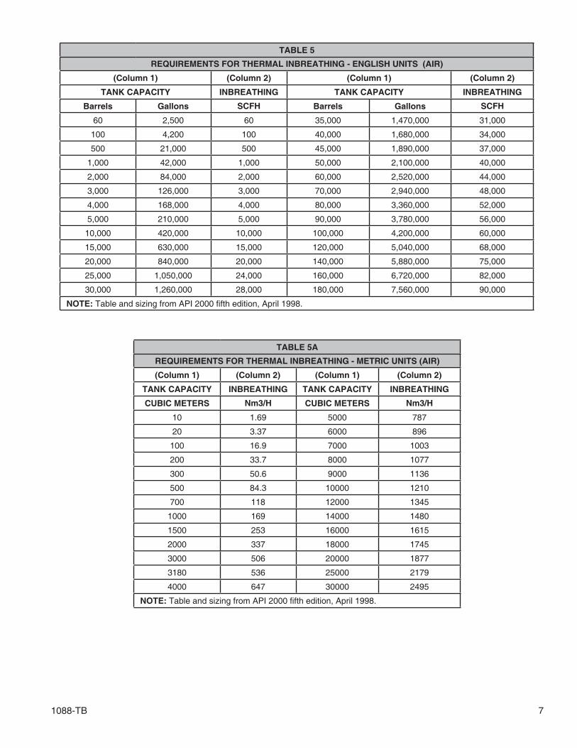
CAPACITY REQUIREMENTS
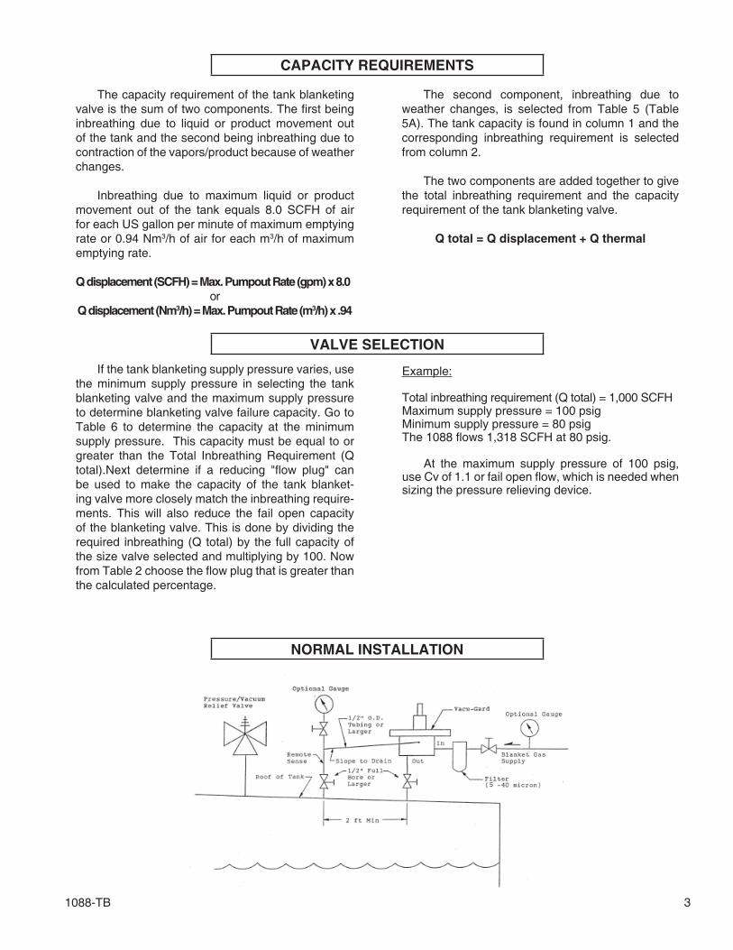
The capacity requirement of the tank blanketing valve is the sum of two components. The fi rst being inbreathing due to liquid or product movement out of the tank and the second being inbreathing due to contraction of the vapors/product because of weather changes.
Inbreathing due to maximum liquid or product movement out of the tank equals 8.0 SCFH of air for each US gallon per minute of maximum emptying rate or 0.94 Nm3/h of air for each m3/h of maximum emptying rate.
Q displacement (SCFH) = Max. Pumpout Rate (gpm) x 8.0or
Q displacement (Nm3/h) = Max. Pumpout Rate (m3/h) x .94
The second component, inbreathing due to weather changes, is selected from Table 5 (Table 5A). The tank capacity is found in column 1 and the corresponding inbreathing requirement is selected from column 2.
The two components are added together to give the total inbreathing requirement and the capacity requirement of the tank blanketing valve.
Q total = Q displacement + Q thermal
VALVE SELECTION
If the tank blanketing supply pressure varies, use the minimum supply pressure in selecting the tank blanketing valve and the maximum supply pressure to determine blanketing valve failure capacity. Go to Table 6 to determine the capacity at the minimum supply pressure. This capacity must be equal to or greater than the Total Inbreathing Requirement (Q total).Next determine if a reducing "fl ow plug" can be used to make the capacity of the tank blanket-ing valve more closely match the inbreathing require-ments. This will also reduce the fail open capacity of the blanketing valve. This is done by dividing the required inbreathing (Q total) by the full capacity of the size valve selected and multiplying by 100. Now from Table 2 choose the fl ow plug that is greater than the calculated percentage.
Example:
Total inbreathing requirement (Q total) = 1,000 SCFHMaximum supply pressure = 100 psigMinimum supply pressure = 80 psigThe 1088 fl ows 1,318 SCFH at 80 psig.
At the maximum supply pressure of 100 psig, use Cv of 1.1 or fail open fl ow, which is needed when sizing the pressure relieving device.
NORMAL INSTALLATION
1088-TB4
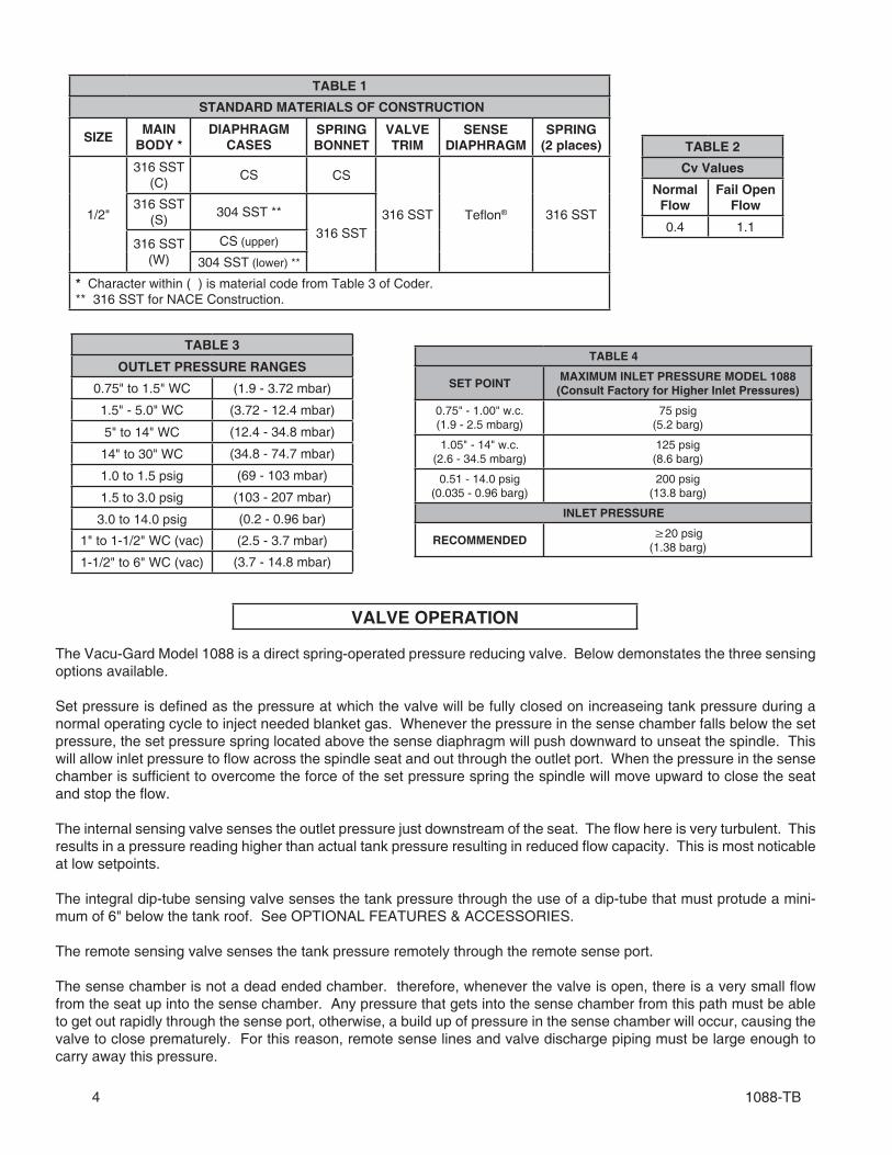
TABLE 1
STANDARD MATERIALS OF CONSTRUCTION
SIZEMAIN
BODY *DIAPHRAGM
CASESSPRING BONNET
VALVE TRIM
SENSE DIAPHRAGM
SPRING (2 places)
1/2"
316 SST(C)
CS CS
316 SST Tefl on® 316 SST316 SST
(S)304 SST **
316 SST316 SST
(W)CS (upper)
304 SST (lower) **
* Character within ( ) is material code from Table 3 of Coder.** 316 SST for NACE Construction.
TABLE 2
Cv Values
Normal Flow
Fail Open Flow
0.4 1.1
TABLE 3
OUTLET PRESSURE RANGES
0.75" to 1.5" WC (1.9 - 3.72 mbar)
1.5" - 5.0" WC (3.72 - 12.4 mbar)
5" to 14" WC (12.4 - 34.8 mbar)
14" to 30" WC (34.8 - 74.7 mbar)
1.0 to 1.5 psig (69 - 103 mbar)
1.5 to 3.0 psig (103 - 207 mbar)
3.0 to 14.0 psig (0.2 - 0.96 bar)
1" to 1-1/2" WC (vac) (2.5 - 3.7 mbar)
1-1/2" to 6" WC (vac) (3.7 - 14.8 mbar)
VALVE OPERATION
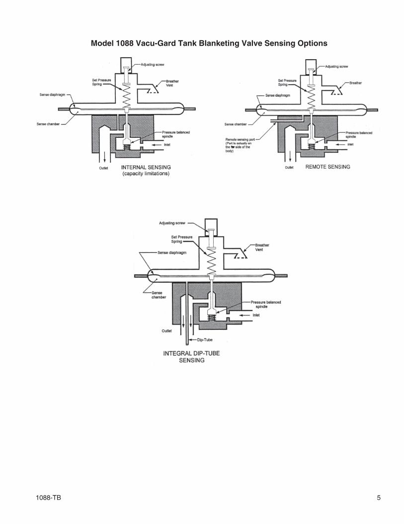
The Vacu-Gard Model 1088 is a direct spring-operated pressure reducing valve. Below demonstates the three sensing options available.
Set pressure is defi ned as the pressure at which the valve will be fully closed on increaseing tank pressure during a normal operating cycle to inject needed blanket gas. Whenever the pressure in the sense chamber falls below the set pressure, the set pressure spring located above the sense diaphragm will push downward to unseat the spindle. This will allow inlet pressure to fl ow across the spindle seat and out through the outlet port. When the pressure in the sense chamber is suffi cient to overcome the force of the set pressure spring the spindle will move upward to close the seat and stop the fl ow.
The internal sensing valve senses the outlet pressure just downstream of the seat. The fl ow here is very turbulent. This results in a pressure reading higher than actual tank pressure resulting in reduced fl ow capacity. This is most noticable at low setpoints.
The integral dip-tube sensing valve senses the tank pressure through the use of a dip-tube that must protude a mini-mum of 6" below the tank roof. See OPTIONAL FEATURES & ACCESSORIES.
The remote sensing valve senses the tank pressure remotely through the remote sense port.
The sense chamber is not a dead ended chamber. therefore, whenever the valve is open, there is a very small fl ow from the seat up into the sense chamber. Any pressure that gets into the sense chamber from this path must be able to get out rapidly through the sense port, otherwise, a build up of pressure in the sense chamber will occur, causing the valve to close prematurely. For this reason, remote sense lines and valve discharge piping must be large enough to carry away this pressure.
TABLE 4
SET POINTMAXIMUM INLET PRESSURE MODEL 1088
(Consult Factory for Higher Inlet Pressures)
0.75" - 1.00" w.c.(1.9 - 2.5 mbarg)
75 psig(5.2 barg)
1.05" - 14" w.c.(2.6 - 34.5 mbarg)
125 psig(8.6 barg)
0.51 - 14.0 psig(0.035 - 0.96 barg)
200 psig(13.8 barg)
INLET PRESSURE
RECOMMENDED≥20 psig
(1.38 barg)
1088-TB 5
Model 1088 Vacu-Gard Tank Blanketing Valve Sensing Options
6 1088-TB
STANDARD INFORMATION
The tank blanketing valve is not a substitute for the vacuum relief device.
API Standard 2000 states, "The design of a gas-repressuring system to eliminate the requirement for vacuum relief valves is beyond the scope of this standard and should be considered only when the induction of air represents a haz-ard equal to or greater than failure of the tank".
The tank blanketing valve failure must be taken into account when considering possible causes of overpressure in a tank.
API Standard 2000 states, "When the possible causes of overpressure or vacuum in a tank are be-ing determined, other circumstances resulting from equipment failures and operating errors must be considered and evaluated by the designer." Failure of the tank blanketing valve can result in unrestricted gas fl ow into the tank, reduced gas fl ow or complete loss of the gas fl ow.
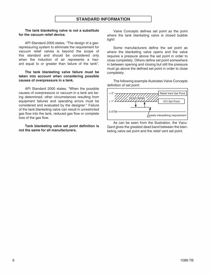
Tank blanketing valve set point defi nition is not the same for all manufacturers.
Relief Vent Set Point+ 2"
VCI Set Point+ 1"
0 ATMmeets inbreathing requirement
As can be seen from the illustration, the Vacu-Gard gives the greatest dead band between the blan-keting valve set point and the relief vent set point.
DEAD BAND
Valve Concepts defi nes set point as the point where the tank blanketing valve is closed bubble tight!
Some manufacturers defi ne the set point as where the blanketing valve opens and the valve requires a pressure above the set point in order to close completely. Others defi ne set point somewhere in between opening and closing but still the pressure must go above the defi ned set point in order to close completely.
The following example illustrates Valve Concepts defi nition of set point:
1088-TB 7
TABLE 5
REQUIREMENTS FOR THERMAL INBREATHING - ENGLISH UNITS (AIR)
(Column 1) (Column 2) (Column 1) (Column 2)
TANK CAPACITY INBREATHING TANK CAPACITY INBREATHING
Barrels Gallons SCFH Barrels Gallons SCFH
60 2,500 60 35,000 1,470,000 31,000
100 4,200 100 40,000 1,680,000 34,000
500 21,000 500 45,000 1,890,000 37,000
1,000 42,000 1,000 50,000 2,100,000 40,000
2,000 84,000 2,000 60,000 2,520,000 44,000
3,000 126,000 3,000 70,000 2,940,000 48,000
4,000 168,000 4,000 80,000 3,360,000 52,000
5,000 210,000 5,000 90,000 3,780,000 56,000
10,000 420,000 10,000 100,000 4,200,000 60,000
15,000 630,000 15,000 120,000 5,040,000 68,000
20,000 840,000 20,000 140,000 5,880,000 75,000
25,000 1,050,000 24,000 160,000 6,720,000 82,000
30,000 1,260,000 28,000 180,000 7,560,000 90,000
NOTE: Table and sizing from API 2000 fi fth edition, April 1998.
TABLE 5A
REQUIREMENTS FOR THERMAL INBREATHING - METRIC UNITS (AIR)
(Column 1) (Column 2) (Column 1) (Column 2)
TANK CAPACITY INBREATHING TANK CAPACITY INBREATHING
CUBIC METERS Nm3/H CUBIC METERS Nm3/H
10 1.69 5000 787
20 3.37 6000 896
100 16.9 7000 1003
200 33.7 8000 1077
300 50.6 9000 1136
500 84.3 10000 1210
700 118 12000 1345
1000 169 14000 1480
1500 253 16000 1615
2000 337 18000 1745
3000 506 20000 1877
3180 536 25000 2179
4000 647 30000 2495
NOTE: Table and sizing from API 2000 fi fth edition, April 1998.
8 1088-TB
TABLE 6
TANK BLANKETING VALVE CAPACITIES
INLET PRESSURE psig (Bar)
PLUG SIZE CAPACITIES IN SCFH (Nm3/h) FOR AIR
10% 40% 100%
10 (.7) 28 (.7) 112 (3.0) 280 (7.5)
20 (1.4) 45 (1.2) 181 (4.8) 452 (12.1)
30 (2.1) 60 (1.6) 241 (6.4) 602 (16.1)
40 (2.8) 74 (2.0) 299 (8.0) 747 (20.0)
50 (3.4) 89 (2.3) 356 (9.5) 891 (23.9)
60 (4.1) 103 (2.7) 414 (11.1) 1,035 (27.7)
70 (4.8) 117 (3.1) 471 (12.6) 1,177 (31.5)
80 (5.5) 131 (3.5) 527 (14.1) 1,318 (35.3)
90 (6.2) 146 (3.9) 584 (15.6) 1,460 (39.1)
100 (6.9) 160 (4.3) 639 (17.1) 1,599 (42.9)
110 (7.6) 174 (4.6) 697 (18.7) 1,742 (46.7)
120 (8.3) 188 (5.0) 752 (20.1) 1,882 (50.4)
130 (9.0) 202 (5.4) 809 (21.6) 2,023 (54.2)
140 (9.6) 216 (5.8) 865 (23.1) 2,164 (58.0)
150 (10.3) 230 (6.1) 921 (24.7) 2,303 (61.7)
160 (11.0) 244 (6.5) 978 (26.2) 2,445 (65.5)
170 (11.7) 258 (6.9) 1034 (27.7) 2,585 (69.3)
180 (12.4) 272 (7.3) 1090 (29.2) 2,726 (73.1)
190 (13.1) 286 (7.6) 1147 (30.7) 2,867 (76.8)
200 (13.8) MAX 300 (8.0) 1202 (32.2) 3,005 (80.5)
INLET PRESSURE psig (Bar)
PLUG SIZE CAPACITIES IN SCFH (Nm3/h) FOR NITROGEN
10% 40% 100%
10 (.7) 28 (.7) 114 (3.0) 284 (7.6)
20 (1.4) 46 (1.2) 183 (4.9) 459 (12.3)
30 (2.1) 61 (1.6) 245 (6.5) 614 (16.4)
40 (2.8) 76 (2.0) 305 (8.2) 762 (20.4)
50 (3.4) 91 (2.4) 364 (9.7) 910 (24.3)
60 (4.1) 105 (2.8) 422 (11.3) 1,056 (28.3)
70 (4.8) 120 (3.2) 480 (12.9) 1,201 (32.2)
80 (5.5) 134 (3.6) 537 (14.4) 1,344 (36.0)
90 (6.2) 149 (4.0) 596 (16.0) 1,489 (40.0)
100 (6.9) 163 (4.3) 653 (17.5) 1,632 (43.7)
110 (7.6) 178 (4.7) 711 (19.0) 1,778 (47.6)
120 (8.3) 192 (5.1) 768 (20.6) 1,921 (51.5)
130 (9.0) 206 (5.5) 826 (22.1) 2,065 (55.3)
140 (9.6) 221 (5.9) 883 (23.7) 2,208 (59.2)
150 (10.3) 235 (6.3) 940 (25.2) 2,351 (63.0)
160 (11.0) 249 (6.7) 998 (26.7) 2,495 (66.9)
170 (11.7) 264 (7.1) 1055 (28.2) 2,638 (70.7)
180 (12.4) 278 (7.4) 1113 (29.8) 2,782 (74.5)
190 (13.1) 292 (7.8) 1170 (31.3) 2,925 (78.4)
200 (13.8) MAX 307 (8.2) 1227 (32.9) 3,067 (82.2)
Note: For internal sensing use 1/4 of values shown.
1088-TB 9
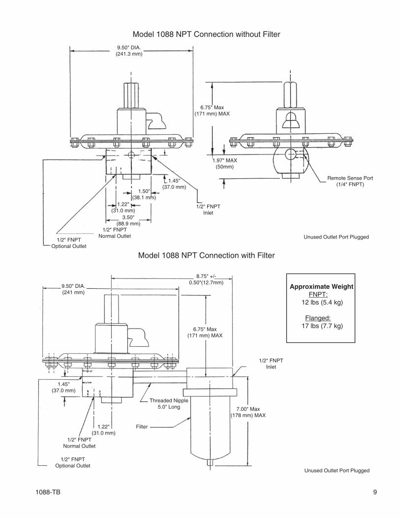
Model 1088 NPT Connection without Filter
Model 1088 NPT Connection with Filter
9.50" DIA.(241 mm)
9.50" DIA.(241.3 mm)
6.75" Max(171 mm) MAX
6.75" Max(171 mm) MAX
1/2" FNPTInlet
1.97" MAX(50mm)
Remote Sense Port(1/4" FNPT)
1/2" FNPTOptional Outlet
1/2" FNPTNormal Outlet
3.50"(88.9 mm)
1.22"(31.0 mm)
1.45"(37.0 mm)
1.50"(38.1 mm)
1/2" FNPTInlet
1/2" FNPTOptional Outlet
1/2" FNPTNormal Outlet
1.22"(31.0 mm)
1.45"(37.0 mm)
Filter
7.00" Max(178 mm) MAX
Threaded Nipple5.0" Long
8.75" +/-0.50"(12.7mm)
Unused Outlet Port Plugged
Unused Outlet Port Plugged
Approximate Weight FNPT: 12 lbs (5.4 kg)
Flanged: 17 lbs (7.7 kg)
10 1088-TB
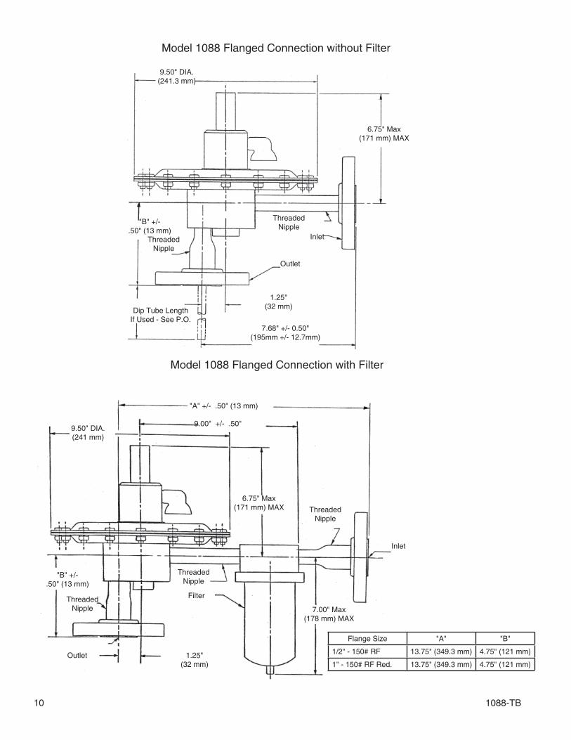
Model 1088 Flanged Connection without Filter
Model 1088 Flanged Connection with Filter
Inlet
7.00" Max(178 mm) MAX
ThreadedNipple
"A" +/- .50" (13 mm)
9.00" +/- .50"
6.75" Max(171 mm) MAX
9.50" DIA.(241 mm)
ThreadedNipple
Filter
1.25"(32 mm)
Outlet
ThreadedNipple
"B" +/- .50" (13 mm)
Flange Size "A" "B"
1/2" - 150# RF 13.75" (349.3 mm) 4.75" (121 mm)
1" - 150# RF Red. 13.75" (349.3 mm) 4.75" (121 mm)
9.50" DIA.(241.3 mm)
6.75" Max(171 mm) MAX
Inlet
ThreadedNipple
Outlet
ThreadedNipple
"B" +/- .50" (13 mm)
1.25"(32 mm)
7.68" +/- 0.50"(195mm +/- 12.7mm)
Dip Tube LengthIf Used - See P.O.

1088-TB 11
OPTIONAL FEATURES & ACCESSORIES
Supply Pressure Gauge
To provide local indication of supply pressure.
• Standard ABS gauge with carbon steel fi tting.• Stainless gauge with 316 SST fi tting.
Control Pressure Gauge
To provide local indication of actual tank pressure.
• Standard Magnehelic® gauge with carbon steel fi tting.• Stainless gauge with 316 SST fi tting.
Purge
A purge is used to prevent tank vapors from en-tering into the valve. One Variable Area Flow meter (Rotameter) is used to purge both the sense line and the outlet. The combined fl ow is 1 - 1.5 SCFH. VCI advises the use of a purge when tank vapors may solidify or crystallize when cooled to ambient tem-perature. A purge will also extend the service life of the valve if 316 SST is not compatible with the tank va-pors.
• Standard Rotameter used has a 316 SST body with glass tube.
Sense with Dip Tube (patented)
This option provides a sense connection into the tank through the vertical outlet of the valve. This can be useful when no tank connection is available for the standard external sense.• The dip tube length should be sized so that it protrudes 6" to 8" below the tank roof into the tank.• The dip tube diameter is 0.375" (9.52 mm).• Standard material is 316 SST.
PV-Gard Manifold
The PV-Manifold allows for a very compact in-stallation of a blanketing valve and vent valve on one single tank nozzle. Normally, an installation of this type requires at least three different nozzles; one for the blanketing valve, one for the vent valve, and one for the remote sensing for the blanketing valve. Us-ing the PV-Manifold, only one tank nozzle is required.
Inline Filter
The use of an inline fi lter is not required for regu-lar blanketing gases. An inline strainer or fi lter can be provided in case the blanketing gas used is not suffi ciently clean.
NACE Construction
In ter nal wetted por tions meet NACE stan dard MR0175, when the ex te rior of the reg u la tor is not directly ex posed to a sour gas en vi ron ment, bur ied, in su lated or oth er wise de nied di rect at mos pheric ex- po sure. SST body and Trim - Buna-N or FKM Seat and Seal ma te ri als only. NPT or Flanged Connection. (Flanged version re quires post-weld stress re liev ing by heat treat ing.)
NOTE: Customer must specify length of Dip Tube .
Valve Concepts, Inc.A Cashco Company607 W. 15th StreetEllsworth, KS 67439PH (785) 472-4461 Fax. # (785) 472-3539www.cashco.comemail: [email protected] in U.S.A. Model 1088 – TB
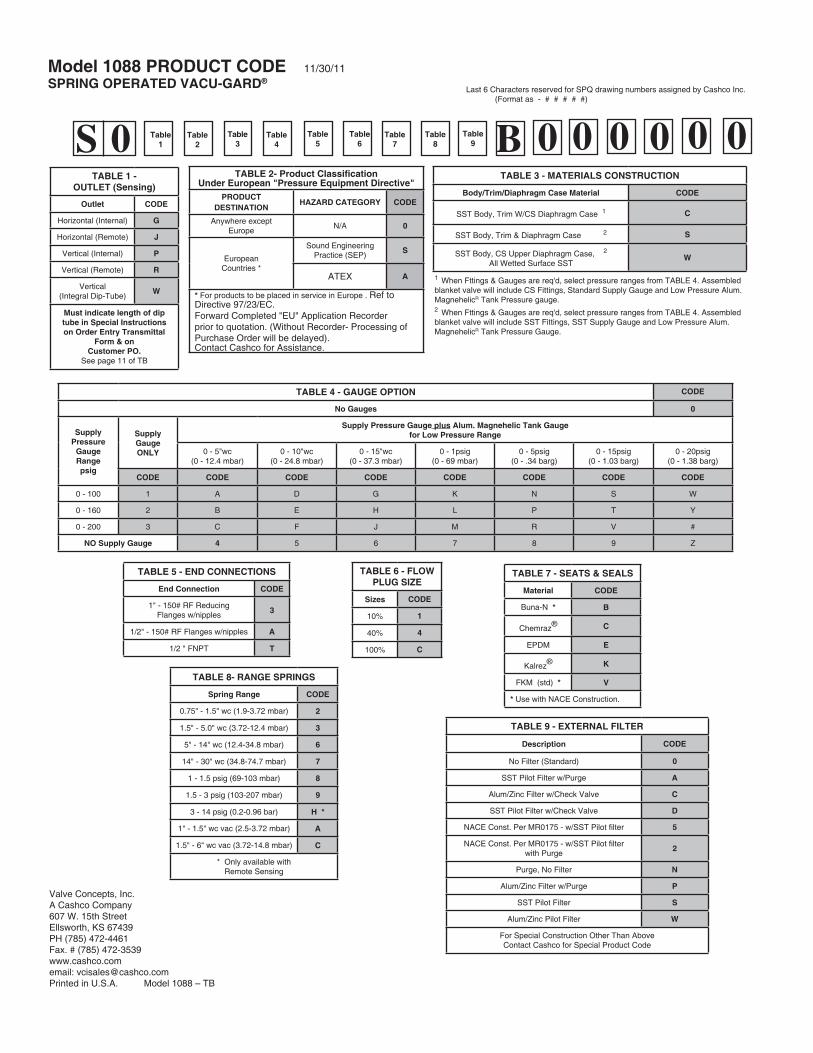
Model 1088 PRODUCT CODE 11/30/11
SPRING OPERATED VACU-GARD®
TABLE 3 - MATERIALS CONSTRUCTION
Body/Trim/Diaphragm Case Material CODE
SST Body, Trim W/CS Diaphragm Case 1 C
SST Body, Trim & Diaphragm Case 2 S
SST Body, CS Upper Diaphragm Case, 2
All Wetted Surface SSTW
TABLE 7 - SEATS & SEALS
Material CODE
Buna-N * B
Chemraz® C
EPDM E
Kalrez® K
FKM (std) * V
* Use with NACE Construction.
TABLE 9 - EXTERNAL FILTER
Description CODE
No Filter (Standard) 0
SST Pilot Filter w/Purge A
Alum/Zinc Filter w/Check Valve C
SST Pilot Filter w/Check Valve D
NACE Const. Per MR0175 - w/SST Pilot fi lter 5
NACE Const. Per MR0175 - w/SST Pilot fi lterwith Purge
2
Purge, No Filter N
Alum/Zinc Filter w/Purge P
SST Pilot Filter S
Alum/Zinc Pilot Filter W
For Special Construction Other Than AboveContact Cashco for Special Product Code
TABLE 5 - END CONNECTIONS
End Connection CODE
1" - 150# RF ReducingFlanges w/nipples
3
1/2" - 150# RF Flanges w/nipples A
1/2 " FNPT T
TABLE 8- RANGE SPRINGS
Spring Range CODE
0.75" - 1.5" wc (1.9-3.72 mbar) 2
1.5" - 5.0" wc (3.72-12.4 mbar) 3
5" - 14" wc (12.4-34.8 mbar) 6
14" - 30" wc (34.8-74.7 mbar) 7
1 - 1.5 psig (69-103 mbar) 8
1.5 - 3 psig (103-207 mbar) 9
3 - 14 psig (0.2-0.96 bar) H *
1" - 1.5" wc vac (2.5-3.72 mbar) A
1.5" - 6" wc vac (3.72-14.8 mbar) C
* Only available withRemote Sensing
S 0 0 0 0 000Table2
Table1
Table3
Table4
Table6
Table5
Table7
TABLE 6 - FLOW PLUG SIZE
Sizes CODE
10% 1
40% 4
100% C
Table8 B
Last 6 Characters reserved for SPQ drawing numbers assigned by Cashco Inc. (Format as - # # # # #)
Table9
1 When Fttings & Gauges are req'd, select pressure ranges from TABLE 4. Assembled blanket valve will include CS Fittings, Standard Supply Gauge and Low Pressure Alum. MagnehelicR Tank Pressure gauge.2 When Fttings & Gauges are req'd, select pressure ranges from TABLE 4. Assembled blanket valve will include SST Fittings, SST Supply Gauge and Low Pressure Alum. MagnehelicR Tank Pressure Gauge.
TABLE 4 - GAUGE OPTION CODE
No Gauges 0
SupplyPressure
GaugeRangepsig
SupplyGaugeONLY
Supply Pressure Gauge plus Alum. Magnehelic Tank Gauge for Low Pressure Range
0 - 5"wc(0 - 12.4 mbar)
0 - 10"wc(0 - 24.8 mbar)
0 - 15"wc(0 - 37.3 mbar)
0 - 1psig(0 - 69 mbar)
0 - 5psig(0 - .34 barg)
0 - 15psig(0 - 1.03 barg)
0 - 20psig(0 - 1.38 barg)
CODE CODE CODE CODE CODE CODE CODE CODE
0 - 100 1 A D G K N S W
0 - 160 2 B E H L P T Y
0 - 200 3 C F J M R V #
NO Supply Gauge 4 5 6 7 8 9 Z
TABLE 1 -OUTLET (Sensing)
Outlet CODE
Horizontal (Internal) G
Horizontal (Remote) J
Vertical (Internal) P
Vertical (Remote) R
Vertical(Integral Dip-Tube)
W
Must indicate length of dip tube in Special Instructions on Order Entry Transmittal
Form & onCustomer PO.
See page 11 of TB
TABLE 2- Product Classifi cationUnder European "Pressure Equipment Directive"
PRODUCTDESTINATION
HAZARD CATEGORY CODE
Anywhere exceptEurope
N/A 0
EuropeanCountries *
Sound EngineeringPractice (SEP)
S
ATEX A
* For products to be placed in service in Europe . Ref to Directive 97/23/EC.Forward Completed "EU" Application Recorderprior to quotation. (Without Recorder- Processing of Purchase Order will be delayed).Contact Cashco for Assistance.