Embed Size (px)
Citation preview

Installation & Maintenance Guide
PROTECTOSEAL SERIES NO. 102" Pilot Operating Tank Blanketing Valve
The Protectoseal Series 10, 2” Pilot Operated Tank Blanketing Valve wasdeveloped as an effective means of controlling the formation of explosivevapor / air mixtures in storage tanks via gas blanketing. Installation of thedevice will require additional safety equipment for optimal operating perfor-mance. Prior to installation of Protectoseal’s 2" Tank Blanketing Valve, each ofthe following should be considered as an integral part of the system’s design:
1. Emergency Venting2. Pressure and Vacuum Relief Venting3. Safety Shut-off Valves4. Supply Gas Filtering
For a comprehensive understanding of the typical tank blanketing installationplease refer to the Series 10, 2” Pilot Operated Tank Blanketing Valve ProductSpecification Sheet or User Manual.
Drawings, specifications and dimensions are subject to change without notice, contact factory for latest information.
PROTECTOSEAL®
Safety Without Compromise

DANGER:Indicates an immi-
nently hazardous situation which, if notavoided will result in death or seriousinjury.
PROTECTOSEAL SERIES NO. 102" TANK BLANKETING VALVE
Installation & Maintenance Guide
SAFETY INFORMATION INSTRUCTIONS FOR SAFE OPERATION AND MAINTENANCEThis instruction manual is intended to familiarize the appropriate personnel with theoperation, servicing and safety procedures associated with the Series 10, 2" BlanketingValve. This manual should be kept available to all operating and maintenance personnel.
Make sure that any person installing and/or operating the tank blanketing valve device:1. Is technically qualified and competent.2. Has completely read this Installation and Maintenance Guide and understands the
dangers associated with improper installation and misuse.3. Uses proper personal protection equipiment (including hearing protection).
1. Improper installation and misuse may be extremely dangerousto nearby personnel and can cause permanent damage to thedevice and associated tank equipment.
2. In the event of a blanketing valve failure, unrestricted gas flow,reduced gas flow or complete loss of gas flow may result.Without properly sized venting devices and suitable safetyshut-off equipment, excessive pressure or vacuum conditionsmay develop.For a comprehensive understanding of the typical blanketinginstallation please refer to the Series 10, Product Spec Sheetor User Manual
1. Do not attempt to adjust the set point or perform maintenanceon the device without first isolating the valve from theupstream high pressure gas supply and downstream tankvapors.
2. Verify chemical capatibility with all blanketing valveparts/accessories prior to installation. Process vapors may beexposed to all components during operation. Contact the fac-tory for product data sheets.
3. It is essential that hearing protection be used when in thevacinity of an operational blanketing valve. Sound pressuremeasurements in excess of 140 dB have been recorded at theoutlet.
1. Refer to Fig. 2 (recommended sense line length vs. I.D.) priorto installing the valve. The sense line must be kept open andunobstructed and have an inside diameter 1/2" (12.7 mm)sch. 40 pipe. The line should be located at least five (5) feetfrom the outlet of the blanketing valve. Long sense line runswill require larger diameters as recommended in Fig. 2. Caremust be taken during installation so that liquid and condensa-tion drain away from the blanketing valve housing.
2. SUPPLY GAS MUST BE DRY AND FREE OF PARTICULATES.Liquid in the supply line will cause piston lubrication washoutwhich may lead to premature valve failure. SUPPLY LINE FIL-TERING IS HIGHLY RECOMMENDED.
WARNING:Indicates a potentially
hazardous situation which, if not avoided,could result in death or serious injury.
Safety Words: A safety related messageis identified by a safety alert symbol and asignal word to indicate the level of riskinvolved with a particular hazard. Per ANSIstandard Z535.4-1998 the definitions ofthe signal words are as follows:
NOTICE:Indicates a statement
of company policy directly or indirectlyrelated to the safety of personnel or pro-tection of property. This signal word shouldnot be associated directly with hazardoussituations and shall not be used in place ofDANGER, WARNING or CAUTION.
PROTECTOSEAL SERIES NO. 102" TANK BLANKETING VALVE
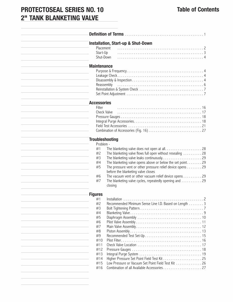
Table of Contents
Definition of Terms . . . . . . . . . . . . . . . . . . . . . . . . . . . . . . . . . . . . . . . . . . . 1
Installation, Start-up & Shut-DownPlacement . . . . . . . . . . . . . . . . . . . . . . . . . . . . . . . . . . . . . . . . . . . . . . . 2Start-Up . . . . . . . . . . . . . . . . . . . . . . . . . . . . . . . . . . . . . . . . . . . . . . . 3Shut-Down . . . . . . . . . . . . . . . . . . . . . . . . . . . . . . . . . . . . . . . . . . . . . . . 4
MaintenancePurpose & Frequency. . . . . . . . . . . . . . . . . . . . . . . . . . . . . . . . . . . . . . . . . . 4Leakage Check . . . . . . . . . . . . . . . . . . . . . . . . . . . . . . . . . . . . . . . . . . . . . . . 4Disassembly & Inspection . . . . . . . . . . . . . . . . . . . . . . . . . . . . . . . . . . . . . . . 4Reassembly . . . . . . . . . . . . . . . . . . . . . . . . . . . . . . . . . . . . . . . . . . . . . . . 6Reinstallation & System Check . . . . . . . . . . . . . . . . . . . . . . . . . . . . . . . . . . . 7Set Point Adjustment . . . . . . . . . . . . . . . . . . . . . . . . . . . . . . . . . . . . . . . . . . 7
AccessoriesFilter . . . . . . . . . . . . . . . . . . . . . . . . . . . . . . . . . . . . . . . . . . . . . . 16Check Valve . . . . . . . . . . . . . . . . . . . . . . . . . . . . . . . . . . . . . . . . . . . . . . 17Pressure Gauges . . . . . . . . . . . . . . . . . . . . . . . . . . . . . . . . . . . . . . . . . . . . 18Integral Purge Accessories. . . . . . . . . . . . . . . . . . . . . . . . . . . . . . . . . . . . . 18Field Test Accessories . . . . . . . . . . . . . . . . . . . . . . . . . . . . . . . . . . . . . . . . 21Combination of Accessories (Fig. 16) . . . . . . . . . . . . . . . . . . . . . . . . . . . . . 27
TroubleshootingProblem -#1 The blanketing valve does not open at all. . . . . . . . . . . . . . . . . . . . 28#2 The blanketing valve flows full open without resealing . . . . . . . . . . 28#3 The blanketing valve leaks continuously. . . . . . . . . . . . . . . . . . . . . . 29#4 The blanketing valve opens above or below the set point . . . . . . . . 29#5 The pressure vent or other pressure relief device opens . . . . . . . . 29
before the blanketing valve closes#6 The vacuum vent or other vacuum relief device opens . . . . . . . . . . 29#7 The blanketing valve cycles, repeatedly opening and . . . . . . . . . . . 29
closing
Figures#1 Installation . . . . . . . . . . . . . . . . . . . . . . . . . . . . . . . . . . . . . . . . 2#2 Recommended Minimum Sense Line I.D. Based on Length . . . . . . . . 3#3 Bolt Tightening Pattern. . . . . . . . . . . . . . . . . . . . . . . . . . . . . . . . . . . 7#4 Blanketing Valve . . . . . . . . . . . . . . . . . . . . . . . . . . . . . . . . . . . . . . . . 9#5 Diaphragm Assembly . . . . . . . . . . . . . . . . . . . . . . . . . . . . . . . . . . . 10#6 Pilot Valve Assembly . . . . . . . . . . . . . . . . . . . . . . . . . . . . . . . . . . . . 11#7 Main Valve Assembly. . . . . . . . . . . . . . . . . . . . . . . . . . . . . . . . . . . . 12#8 Piston Assembly . . . . . . . . . . . . . . . . . . . . . . . . . . . . . . . . . . . . . . . 13#9 Recommended Test Set-Up . . . . . . . . . . . . . . . . . . . . . . . . . . . . . . . 15#10 Pilot Filter. . . . . . . . . . . . . . . . . . . . . . . . . . . . . . . . . . . . . . . . . . . . 16#11 Check Valve Location . . . . . . . . . . . . . . . . . . . . . . . . . . . . . . . . . . . 17#12 Pressure Gauge s . . . . . . . . . . . . . . . . . . . . . . . . . . . . . . . . . . . . . . 18#13 Integral Purge System . . . . . . . . . . . . . . . . . . . . . . . . . . . . . . . . . . 19#14 Higher Pressure Set Point Field Test Kit . . . . . . . . . . . . . . . . . . . . . 25#15 Low Pressure or Vacuum Set Point Field Test Kit . . . . . . . . . . . . . . 26#16 Combination of all Available Accessories . . . . . . . . . . . . . . . . . . . . . 27

PROTECTOSEAL SERIES NO. 102" TANK BLANKETING VALVE
Installation & Maintenance GuidePage 1
Definition of Terms Some of the terms used in this manual are defined below:Conservation Vent: A device which is connected to a storage tank and regulates thepressure therein. Conservation vents may provide pressure relief, vacuum relief, or both.Pallets move in direct response to tank pressure allowing flow out of or into the tank. Palletmovement may be controlled by weight-loading, spring-loading, or a pilot valve.Deadband: The total pressure difference between the blanketing valve opening pressure(or set point) and resealing pressure. This applies to the main valve; some leakage throughthe pilot will occur above the main valve reseating pressureDiaphragm Chamber: The portion of the pilot valve which contains the sensediaphragm.Dome Pressure: The pressure in the dome volume.Dome Volume: The chamber between the poppet in the pilot valve and the piston in themain valve.Emergency Vent: A conservation vent which provides additional pressure relief toaccommodate extraordinary conditions such as fire exposure to a tank or full-open failureof a blanketing valve.Flow Orifice Plate: A circular orifice plate that can be threaded into the inlet body toreduce the blanketing valve’s flow capacity.Inlet Port: The connection to the blanketing valve coming from the gas supply line.Main Valve: The portion of the blanketing valve through which the supply gas flows intothe storage tank.Orifice: A small diameter passage in the line between the inlet port and the dome volume.Outlet Port: The connection to the blanketing valve leading to the storage tank.Pilot Valve: The portion of the blanketing valve which senses the tank pressure and con-trols the dome pressure.Piston: The component in the main valve which moves open from a normally seated posi-tion to allow flow of blanketing gas through the valve.Piston Spring: The spring which biases the piston towards the seated position.Poppet: The component in the pilot valve which can move open from a normally seatedposition to allow flow through the valve.Poppet Spring: The spring which biases the poppet towards the seated position.Purge: A very low flow of supply gas directed past the sense line and/or the outlet inorder to keep corrosive vapors away from the blanketing valve.Sense Chamber: The space below the diaphragm chamber to which the pressure fromthe sense line is directed. The pressure in the sense chamber controls the opening andclosing of the pilot and blanketing valve.Sense Diaphragm: A thin, non-metallic disc in the diaphragm chamber which flexes inresponse to changes in tank pressure acting upon it.Sense Line: A line running from the storage tank to the sense port of the blanketingvalve. It feeds tank pressure to the underside of the sense diaphragm.Sense Port: The connection to the blanketing valve coming from the sense line.Set Point: The tank pressure (positive or negative) at which the blanketing valve opens.Soft Goods: The elastomeric components of the blanketing valve including the o-rings,gaskets and diaphragm.Stop: A bolt connected to the sense diaphragm which contacts the poppet to move it inresponse to movement of the sense diaphragm.
Viton® and Kalrez® are registered Trademarks of E.I. DuPont de Nemours & Co., Inc. Chemraz® is a registered Trademark of Green, Tweed& Co., Inc.

PROTECTOSEAL SERIES NO. 102" TANK BLANKETING VALVE
Installation & Maintenance GuidePage 2
Placement
INSTALLATION
The blanketing valve should be placed on top of the storage tank with its outlet connectedvia a short run of pipe to the top of the tank. A second, usually smaller, line runs from thesense port of the valve to a separate connection on the tank. A line coming from the blan-keting gas supply source connects to the valve inlet. The blanketing valve must be posi-tioned so that the inlet line is horizontal and the outlet line points downward. Installationrequires connecting the blanketing valve to three lines as shown below in Fig. 1.
Series 10 Blanketing Valve
Upstream Supply Line Filter/Coalescing Filter5-40 MicronMust meet required �ow
Blanketing GasSupply Line
Full BoreShut-o� Valve
Inlet Port
Tank Roof
Outlet Port
Full BoreShut-o� Valve
Sense Port1/2” NPT
Full BoreShut-o� Valve
Sense Line* 1/2” I.D. Minimum* Slope to drain away from blanketing valve
5 ft. minimum (1.5 m)(Ref. Fig. 2)
Fig. 1
All three lines connected to the valve should have full bore shut-off valves so that the unitcan be isolated and depressurized for maintenance. The use of pipe unions at each con-nection will facilitate installation and removal of the blanketing valve. FEP tape should beapplied to all pipe thread connections. However, be careful in applying it so that the tapecannot get loose inside and potentially clog the blanketing valve. Further details regardingthe three lines follow:
■ SUPPLY LINE: The piping leading to the blanketing valve inlet should be the same pipesize as the inlet connection. This line should incorporate a full bore shut-off valve to enableisolation of the valve from the pressure supply during maintenance. The line should alsoinclude an in-line filter. The filter flow capacity must be higher than the required flowthrough the blanketing valve. For most applications, 5-40 micron filter elements are suit-able, but for contaminated supply lines and lines with excessive liquid buildup, special coa-lescing filter systems are highly recommended. Contact factory for more details.
■ OUTLET LINE: The piping from the valve outlet should be at least the same size as theoutlet connection. This line should also incorporate a full bore-shut-off valve to enable iso-lation of the blanketing valve from the tank during maintenance. A short, straight pipe runfrom the valve outlet to the top of the storage tank is recommended. An extended length ofpipe from the blanketing valve to the tank could lead to main valve chatter causing prema-ture wear and delayed closing of the valve leading to overpressurization of the tank. WARNING: Never connect a 45° or 90° elbow to the outlet.
■ SENSE LINE: The sense line should also include a full bore valve to enable isolation ofthe blanketing valve from the tank during maintenance. The horizontal run from the senseport should be angled slightly down away from the valve to ensure that condensate
WARNING:Follow your company’s
safety procedures to avoid injury to person-nel or damage to equipment.

Start-Up
PROTECTOSEAL SERIES NO. 102" TANK BLANKETING VALVE
will not drain into the valve. 1⁄2" sch. 40 pipe or larger is recommended to ensure thatthere is not a pressure drop from the tank to the valve. This size line is also needed sothat the high pressure supply gas which leaks into the sense chamber while the valve isopen is able to dissipate into the tank so as not to affect closing of the blanketing valve.
The sense line connection to the tank should be far enough from the outlet line connectionto ensure that a static pressure is sensed. On the other hand, the line should not be solong as to lead to any significant pressure drop. Protectoseal recommends extending allsense line runs to at least 5 ft. from the valve outlet. If a longer sense line is necessary,then the size of the tubing or pipe should be increased according to offset pressure dropeffects, see Fig. 2.
It is recommended to keep piping as short as possible for optimum valve performance.
Installation & Maintenance GuidePage 3
10 20 30 40 50 60 70 800.40
0.50
0.60
0.70
0.80
0.90
1.0
1.125
90 100
Max Sense line Length (Ft)(for each 90° bend add 80 diameters to line length)
5
Recommended Sense Line I.D. vs. Length
Min
imum
ID (i
n.)
1 1/8” I.D. Tube
1” Pipe
7/8” I.D. Tube
3/4” Pipe
3/4” I.D. Tube
1/2” Pipe
3/8” Pipe
NOTES:1. Pipe, hose or tube assumed to have a circular cross section, smooth walls & linear �ow.2. Data contained above based on air @ STP.3. Maximum acceptable sense line pressure drop of 0.01” W.C. (0.0007 PSIG/0.04 mmHg).4. All pipe assumed to be Schedule 40.
Fig. 2Recommended Minimum Sense Line I.D. Based on Length
The blanketing valve is tested and set to the customer specified set point (as listed on thelabel) prior to shipment. Further adjustment in the field should not be required. Afterinstallation is complete, follow the steps below in order to put the blanketing valve into ser-vice:1. Open the shut-off valve in the sense line between the blanketing valve and the tank.2. Open the shut-off valve in the outlet line between the blanketing valve and the tank.3. Check the blanketing gas supply line pressure to see that it corresponds to the
pressure or pressure range listed on the label of the blanketing valve. If not, the sup-ply pressure regulator should be adjusted accordingly. The ideal range in which the valve will operate is 40 to 130 PSIG.
4. Slowly open the shut-off valve in the blanketing gas supply line. Pressurizing the blanketing valve slowly pre-loads the valve so that it will not initially pop open.
If the tank pressure is above the blanketing valve set point, then the blanketing valveshould seal immediately. Otherwise the valve will open and flow until the tank pressure risesabove the set point. If the blanketing valve does not reseal at all, consult“Troubleshooting” on page 28.
WARNING:A pressure / vacuum
relieving device large enough to ventexcess pressure and also be an emergencyvacuum relief device should be installed toavoid damage to the tank. Do not exceed the maximum inlet pressurestated on the nameplate; also maintain theminimum pressure.

Shut-Down
Purpose & Frequency
Leakage Check
Disassembly &Inspection
The blanketing valve must be depressurized when removing it from operation. Follow thesteps below for system shut-down:
1. Close the shut-off valve in the blanketing gas supply line.2. Close the shut-off valve in the sense line.3. Pressure between the supply line shut-off and the seals inside the blanketing valve
must be bled off. If the set point pressure is above atmospheric pressure, then thesafest way to do this is to break the seal at the sense port of the blanketing valve.This will allow the pressure in the sense chamber to drop which will open the blanket-ing valve and bleed off the internal pressure into the tank. If the blanketing valve hasa setting below atmospheric pressure, then a different method must be used. In addi-tion to cracking the sense line, a connection between the supply line shut-off valveand the blanketing valve inlet port must be cracked to allow the high pressure gas tobleed out. The connection should be cracked slowly so that the high pressure gasbleeds, not bursts, out.
4. Close the shut-off valve in the outlet line.5. Remove the supply line to the blanketing valve carefully in case there is still trapped
pressure in the line.
Periodic maintenance checks are recommended to ensure that the blanketing valve is ingood operating condition. The blanketing valve should be periodically actuated and all slidingsurfaces and seals properly lubricated to ensure smoothness and good operation. Debris inthe valve, damaged seals or lubrication wash-out are the most likely causes of operatingproblems. The frequency of routine maintenance necessary for the blanketing valve willdepend on the severity of the operating conditions. The valve should be checked within amonth of installation and then as determined appropriate after that. At minimum, the valveshould be checked bi-annually.
Before performing any disassembly, it is a good idea to check for external leakage. This canbe done by spraying or brushing soap around mating connections and bolts. If no leakageis detected around the #18 gasket or the #21 gasket (See Fig. 4), then it should not benecessary to disassemble the diaphragm case while performing routine maintenance.
The following instructions are for maintenance of the standard components of the blanket-ing valve. Refer to the section entitled “Accessory Equipment” for instructions regardingoptional accessories. Also, the diagrams in this section show a unit with standard FNPTinlet and outlet connections. Except where noted, these instructions apply also to units withother inlet and outlet connections.
Protectoseal O-rings and gaskets are available from Protectoseal. See Table 6 on page 14for soft goods kits which can be ordered.
WARNING: The blanketing valve must be completely depressurized before any disassem-bly is performed. Refer to your company’s procedures for handling toxic or hazardousmaterials. See the “shut-down” instructions above.
PROTECTOSEAL SERIES NO. 102" TANK BLANKETING VALVE
Installation/Maintenance GuidePage 4
MAINTENANCE

PROTECTOSEAL SERIES NO. 102" TANK BLANKETING VALVE
Installation & Maintenance GuidePage 5
■ DIAPHRAGM CASERemove the eight (8), #15 bolts, #20 nuts, and #4 lock washers. Carefully pull up theupper case assembly. Reach under the case to hold the #7 set spring in position whilepulling the case up so that the spring and the #6 upper anchor do not fall over. Thediaphragm assembly, see Fig. 4, and the #18 gasket can now be removed and checked. Ifthere is any corrosion or damage to the gasket, it must be replaced.
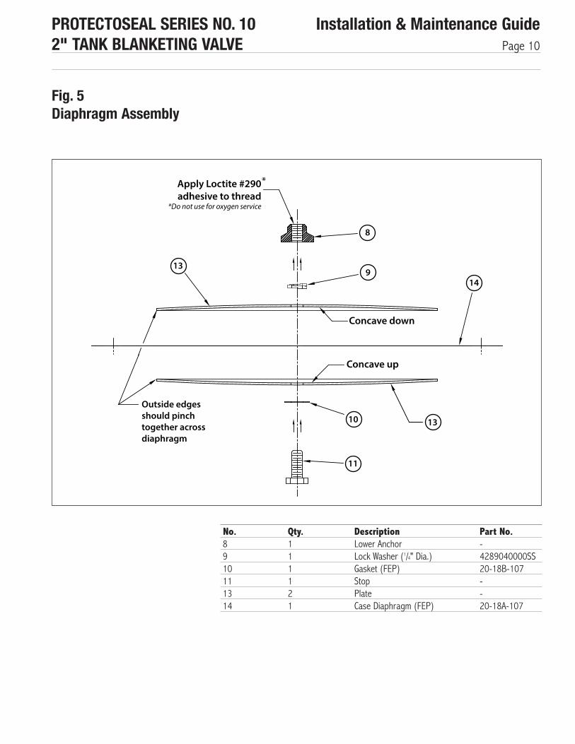
Looking at the diaphragm assembly, the two (2), #13 plates should be clamped flatagainst the #14 diaphragm, and the diaphragm should be free of cracks, cuts or holes.See Fig. 5 for disassembly of the diaphragm assembly. Unthread the #11 stop (machinedhex screw) from the #8 lower anchor. Note: This connection may be very tight due tothread adhesive being applied during assembly. The diaphragm and the #10 gasket shouldbe free of cracks, cuts or holes. To remove the #19 lower case, remove the four (4), #9hex screws. This exposes the #21 gasket which can then be inspected for corrosion ordamage. (See Fig. 4)
■ PILOT VALVE (See Figs. 4, 6 & 7)Position the blanketing valve so that the inlet points downward. Remove the four (4), #33cap screws. Slowly lift up and remove the pilot body. Set aside the #36 main valve includ-ing (Fig. 7) the #38 piston assembly and #39 O-rings.
Refer to Fig. 6. Before removing the #32 lower plug assembly, identify the marks on thenut of the lower plug assembly and the bottom of the pilot body. These marks, which shouldbe lined up with each other, identify the proper position of the lower plug. This position isset at the factory for optimal performance of the blanketing valve. If the marks are not easyto see, then additional marks to identify the position during reassembly (with felt tip pen orotherwise) should be made on the nut and the pilot body before unscrewing the lower plug.Unscrew and remove the #32 lower plug assembly. When this is removed, the #27 poppetand attached parts will come out with it. Be careful not to damage the fine thread on thelower plug after removal.
Grasping the lower plug assembly in one hand and the poppet in the other, firmly tug onthe poppet to pull it out of the lower plug assembly. Be certain to do this in a slow, con-trolled manner so that the #28 poppet spring does not fly out and get lost. If the #19lower case has been removed, then the #23 upper plug can also be removed. The bestway to do this is to slowly insert a phillips-head screwdriver up into the bottom of the smallhole in the upper plug and tap on it to push the plug out. Be very careful not to damagethe inside bottom of the upper plug where the #22 O-ring seats. The O-rings can now beinspected for wear or corrosion.
■ MAIN VALVE (See Figs 7 & 8)The #34 O-ring which is between the main body and the pilot body may be inspected forcorrosion or damage. Slide the #38 piston assembly out of the #36 main body. Inspectthe #38a piston rear (Fig. 8) for scratches or signs of marring. Inspect the #39 and #41O-rings for wear or corrosion. Remove the #44 hex screw to disassemble the pistonassembly. Be careful not to damage the outside of the piston.
It may be possible to inspect the #45 (Fig. 7) flow orifice plate while still assembled insidethe inlet cap, #46. This can be removed and replaced without disassembling the blanketingvalve. Contact your Sales Representative and request Part No. 10-T1A for the necessarytool.

PROTECTOSEAL SERIES NO. 102" TANK BLANKETING VALVE
Installation & Maintenance GuidePage 6
If no leakage between the main body and the inlet cap was detected during the leakagetest, then it will not be necessary to remove the inlet cap (See Fig. 4 & 7). If it is desired toremove the inlet cap, first remove the #51 and #53 bypass tubes by loosening the #47and #50 tube fittings. Then remove the four (4), #43 cap screws and pull the inlet capout from the main body. The #35 O-ring may then be inspected for corrosion or damage. Ifleakage was detected at any connections in the external filter line (going through the #40filter), then these components should be removed for inspection and reapplication of FEPtape on the tapered threads. Refer to page 16 for instructions on cleaning the filter.
When reassembling the blanketing valve, be sure to replace any worn or damaged O-ringsand gaskets.
WARNING: Do not overtighten threaded connections.
■ MAIN VALVE (See Fig. 4, 7 & 8)If the inlet cap has been removed, then replace the #35 O-ring, insert the inlet cap intothe #36 main body, and secure it with the four (4), #43 hex screws and #56 lock wash-ers. Tighten the cap screws to 96 in-lbs. of torque.
Reassemble any connections which were loosened in the external filter line. Apply FEP tapeto any tapered thread connection. Reconnect the #51 and #53 inlet and outlet bypasstubes by tightening the #47 and #50 tube fittings. WARNING: It is critical that the #51tube cutout is located in the center of the #46 inlet cap and perpendicular to the flow.
Before reassembling the #38a piston rear (see Fig. 8), the (2) #39 O-rings should be lib-erally lubricated. Recommended lubricant is DuPont Krytox GPL206 (do not use for oxygenservice). Reassemble the #40 retainer. Before assembling the #44 hex screw to the pis-ton rear, Protectoseal recommends cleaning the threads and applying Loctite* primer#7649 and Loctite* thread locker #277 to where the hex screw engages the #38a pis-ton rear internal threads. Insert the #44 hex screw with #9 lock washer and tighten to 60in-lbs. of torque. Verify that all piston components are concentric before tightening to thefinal torque rating of 150 in-lbs. Push the piston assembly back into the main body. Thepiston should move freely in and out of the bore but should not drop through freely. If itdoes drop through, the wrong size (too small) O-rings must have been put into thegrooves. Verify that the piston assembly is free to move in the main body bore by sliding itback and forth. The piston will fit snug in the bore but should not have to be more thanhand forced past any point.*Loctite not to be used for oxygen service.
■ PILOT VALVE (See Fig. 6, 7 & 4))Before reassembling the pilot valve, the #25 and #26 O-rings should be lubricated.Reinsert all six (6) O-rings. It is also recommended that a conservative amount of anti-seize compound be applied to the threads of the lower plug before threading it back intothe pilot body. Hold the poppet upside down, insert the #28 poppet spring in the groove inthe end, and insert the #29 spring pin into the spring. Slide the #32 lower plug assemblyover the spring pin, spring, and poppet, and pop it into place. The poppet should moveeasily up and down inside the lower plug, being pushed up by the poppet spring. Push the#23 upper plug back into the #30 pilot body if it has been removed (see Fig 7). The ori-entation of the cross holes in the upper plug is not important. Slowly, being careful not todamage the end of the stem on the poppet or the seat at the end of the piston, insert the#34 O-ring into the groove in the main body. Carefully position the pilot body over themain body so that the piston spring fits into the groove in the pilot body. Slowly push thepilot body toward the main body so that the hub of the pilot body slides inside the #34 O-ring. WARNING - BE VERY CAREFUL NOT TO CUT OR DAMAGE THE O-RING! While holdingthe pilot body in place, insert the four (4), #33 cap screws with #56 lock washers and
Reassembly
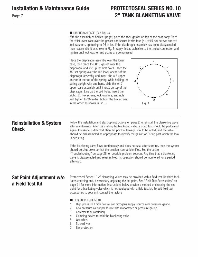
■ DIAPHRAGM CASE (See Fig. 4)With the assembly of bodies upright, place the #21 gasket on top of the pilot body. Placethe #19 lower case over the gasket and secure it with four (4), #15 hex screws and #4lock washers, tightening to 96 in-lbs. If the diaphragm assembly has been disassembled,then reassemble it as shown in Fig. 5. Apply thread adhesive to the thread connection andtighten until lock washer and plates are compressed.
Place the diaphragm assembly over the lowercase, then place the #18 gasket over thediaphragm and line up the bolt holes. Place the#7 set spring over the #8 lower anchor of thediaphragm assembly and insert the #6 upperanchor in the top of the spring. While holding thespring upright with one hand, slide the #17 upper case assembly until it rests on top of thediaphragm. Line up the bolt holes, insert the eight (8), hex screws, lock washers, and nuts and tighten to 96 in-lbs. Tighten the hex screws in the order as shown in Fig. 3.
PROTECTOSEAL SERIES NO. 102" TANK BLANKETING VALVE
Installation & Maintenance GuidePage 7
Reinstallation & SystemCheck
Set Point Adjustment w/oa Field Test Kit
Follow the installation and start-up instructions on page 2 to reinstall the blanketing valveafter maintenance. After reinstalling the blanketing valve, a soap test should be performedagain. If leakage is detected, then the point of leakage should be noted, and the valveshould be disassembled as appropriate to identify the gasket or O-ring past which the leakis occurring.
If the blanketing valve flows continuously and does not seal after start-up, then the systemshould be shut down so that the problem can be identified. See the section“Troubleshooting” on page 28 for possible problem sources. Any time that a blanketingvalve is disassembled and reassembled, its operation should be monitored for a periodafterward.
Protectoseal Series 10 2" blanketing valves may be provided with a field test kit which facil-itates checking and, if necessary, adjusting the set point. See “Field Test Accessories” onpage 21 for more information. Instructions below provide a method of checking the setpoint for a blanketing valve which is not equipped with a field test kit. To add field testaccessories to your unit contact the factory.
■ REQUIRED EQUIPMENT1. High pressure / high flow air (or nitrogen) supply source with pressure gauge2. Low pressure air supply source with manometer or pressure gauge3. Collector tank (optional)4. Clamping device to hold the blanketing valve5. Wrenches6. Screwdriver7. Ear protection
Fig. 3

PROTECTOSEAL SERIES NO. 102" TANK BLANKETING VALVE
Installation & Maintenance GuidePage 8
■ TEST PROCEDURE (See Fig. 9)01. Clamp the blanketing valve securely so that the outlet is open to blow into an area
where it will not cause any harm. WARNING: A high pressure surge of air will exit theoutlet port of the blanketing valve when the valve opens. It is advisable to connect apiece of pipe to the outlet to direct the flow away from the person conducting the testing.
02. Connect a line from a high pressure / high flow air supply source to the blanketing gassupply source, if possible. The recommended inlet supply range is 40 PSIG to 130PSIG.
03. Connect a low pressure supply line to the 1⁄2" NPT sense port. This line must be con-nected to a manometer or pressure gauge for pressure monitoring. Ideally, to obtain amore static pressure supply, this line should come from a collector tank and the pres-sure reading should be taken from the collector tank.
04. Unscrew and remove the #1 cap from the blanketing valve.05. Check that the manometer or gauge is zeroed.06. Set the low pressure supply as follows:
Set Point Range (inches W.C.)-0.5 to 30.0Above 30.0
Low Pressure Supply (inches W.C.)6 above set point2 above set point
07. Pressurize the low pressure supply line connected to the sense port.08. WARNING: Put on ear protection, the flow out of the valve can be extremely loud.09. Pressurize the high pressure supply line connected to the inlet port.10. If the blanketing valve does not seal initially, loosen the #3 jam nut and unscrew the
#2 set screw until it seals completely.11. Opening pressure adjustment: Cycle the pressure to the sense port up and down to
determine the opening point of the blanketing valve. The tank pressure should belowered slowly (at approximately 0.1" W.C. per second for low settings). Adjust the setscrew so that the main valve opens at the desired set point. Please note the following:a) The set point of the Series 10 Blanketing Valve is specified as the pressure at
which the main valve opens.b) The opening of the blanketing valve can be heard, and the opening of the main
valve should be distinguished from the opening of the pilot valve. The pilot valvewill begin to leak at a pressure just above that at which the main valve will openabruptly. The quick opening of the main valve is usually very loud, although thedegree of loudness will depend upon the inlet pressure and the flow capacity (asdetermined by the size of the flow orifice, if any).
c) The main valve reseals above the pressure at which it opens, and the pilotreseals above where the main valve reseals.
12. After the desired opening pressure has been attained, secure the position of the setscrew by tightening the jam nut until the lockwasher is flat.
13. If the opening pressure has been adjusted to a pressure different than that of the setpoint specified on the blanketing valve label, then the blanketing valve should bemarked permanently to identify the new set point.
14. Shut off the inlet pressure, then relieve test tank pressure. Wait for the main valve topop open and relieve pressure.
15. Disconnect all the test lines.16. Screw the cap onto the spring guide and tighten it securely. Be careful not to move
the spring guide.17. Follow the blanketing valve installation and start-up instructions to install the blanket-
ing valve into the system.

OUTLET PORT
43
Sense Chamber
Atmospheric Pressure
56
36
33
56
30
21204
19
18
17
15
52
97
12
6
4
5
3
2
1
5455
INLET PORT
55
PROTECTOSEAL SERIES NO. 102" TANK BLANKETING VALVE
Installation & Maintenance GuidePage 9
Fig. 4Blanketing Valve
No. Qty. Description Part No. No. Qty Description Part No.1 1 Cap - 19 1 Lower Diaphragm Case -2 1 Set Screw - 20 8 Jam Nut (3/8-16UN) 4329180000SS3 1 Jam Nut (3/8-24UN) 4329170000SS 21 1 Gasket 20-18D-*4 9 Lock Washer (Ø3/8) 4289060000SS 30 1 Pilot Body (Fig. 6) -5 1 Spring Guide Assembly - 33 4 Cap Screw (5/16-18UN) 4169157220SS6 1 Upper Anchor - 36 1 Main Body (Fig. 7) --7 1 Setting Spring 20-11(**)-66 43 4 Cap Screw (5/16-18UN) 4169143210SS9 8 Lock Washer (Ø1/4”) 4289040000SS 52 1 Gasket 20-18E-10112 8 Hex Screw (1/4-20UN) 4119141610SS 54 2 Exhaust Hose 10-240BR-6915 8 Hex Screw (3/8-16UN) 4119182010SS 55 4 Tube Fitting 20-F22-6917 1 Upper Diaphragm Case - 56 8 Lock Washer (Ø5/16) 4289050000SS18 1 Diaphragm Case Gasket 20-18C-*
** Suffix ‘A’ through ‘D’, spring dependent on setting - see Product Spec Sheet.* Suffix for the material code, see Table on page 14.
PROTECTOSEAL SERIES NO. 102" TANK BLANKETING VALVE
Installation & Maintenance GuidePage 10
Fig. 5Diaphragm Assembly
13
8
9
Apply Loctite #290adhesive to thread
*Do not use for oxygen service
14
Concave down
Concave up
1310
11
Outside edgesshould pinchtogether acrossdiaphragm
*
No. Qty. Description Part No.8 1 Lower Anchor -9 1 Lock Washer (1/4" Dia.) 4289040000SS10 1 Gasket (FEP) 20-18B-10711 1 Stop - 13 2 Plate -14 1 Case Diaphragm (FEP) 20-18A-107

PROTECTOSEAL SERIES NO. 102" TANK BLANKETING VALVE
Installation & Maintenance GuidePage 11
Fig. 6Pilot Valve Assembly(Item #30)
32
31
29
28
22
27
24
26
24
21
23
25
22
No. Qty. Description Part No.21 1 Gasket 20-18D-*22 2 O-Ring 20-R115-*23 1 Upper Plug =24 2 O-Ring 20-R118-*25 1 O-Ring 20-R109-*26 1 O-Ring 20-R112-*27 1 Poppet =28 1 Poppet Spring -29 1 Spring Pin -30 1 Pilot Body =
31 1 Lock Nut -32 1 Lower Plug =
* Suffix for the material code, see Table 5 on Page 14.= These parts must be replaced as a set.

PROTECTOSEAL SERIES NO. 102" TANK BLANKETING VALVE
Installation & Maintenance GuidePage 12
1/2" FNPT
51
53
50
34
35
37
45
47
49
40
30
4638
36
No. Qty. Description Part No.30 1 Pilot Body -34 1 O-Ring 10-R228-*35 1 O-Ring 10-R238-*36 1 Main Body -37 1 Piston Spring -38 1 Piston Assembly -40 1 Bypass Filter -45 1 Orifice Place 10-236[**]-6946 1 Inlet Body -47 1 Bypass Inlet Fitting -49 2 Filter Fitting 20-F22-6950 1 90° Elbow Fitting 20-F32-6951 1 Bypass Inlet Tube -53 1 Bypass Outlet Tube -
** Suffix ‘A’ through ‘D’ dependent on Flow Reduction % - See Product Spec Sheet.* Suffix for the material code, see Table 5 on page 14.
Fig. 7Main Valve Assembly(Item #36)

PROTECTOSEAL SERIES NO. 102" TANK BLANKETING VALVE
Installation & Maintenance GuidePage 13
Fig 8Piston Assembly(Item #40)
38a 3938b
38c
41
44
40
9
No. Qty. Description Part No.9 1 Lock Washer -38a= 1 Piston Rear -38b 1 Piston Stem -38c 1 Piston Front -39 2 Piston O-Ring 10-R225-*40 1 Retainer -41 1 Main Seal O-Ring 10-R224-*44= 1 Piston Hex Screw -* Suffix for the material code, see Table on Page 14.= Apply Loctite primer #7649 and #Loctite thread locker #277 to mating threads prior
to assembly. Do not use Loctite for oxygen service.

PROTECTOSEAL SERIES NO. 102" TANK BLANKETING VALVE
Installation & Maintenance GuidePage 14
Table 5O-Ring & Gasket Codes &Suffixes
Table 6Soft Goods Kits
Table 7O-Ring Sizes
Model No. Code* Material Part No. Suffix (†)A Buna-N -101B Neoprene -100C Viton® -118D EPDM -136E Kalrez®** -140F Chemraz®** -138
* Digit #7 of part number.** On units with Kalrez® or Chemraz® seals & gaskets the diaphragm case gasket will
be Buna-N.
Kit Part No. Contents10-SGK1-= All O-rings, Gaskets & Diaphragms10-SGK2-= All O-rings
= Suffix for the material code, see Table 5.
No. Part No. Cross Section Dia. I.D.25 20-R109-* .103 0.29926 20-R112-* .103 0.48722 20-R115-* .103 0.67424 20-R118-* .103 0.86241 10-R224-* .139 1.73439 10-R225-* .139 1.85934 10-R228-* .139 2.23435 10-R238-* .139 3.484
* Suffix for the material code, see Table 5.

PROTECTOSEAL SERIES NO. 102" TANK BLANKETING VALVE
Installation & Maintenance GuidePage 15
Fig. 9Recommended TestSet-Up
Low PressureSupply Source
Cap
Set Screw
Jam Nut
Lock Washer
Inlet Port
OptionalTest Stand
Outlet PortCollector Tank
2” Pipe(Minimum)
Bleed toAtmosphere
Manometer orPressure Gauge
Sense Line Hose(Ref. Fig. 2) Sense
Port
NOTE A:5-40 Micron Filter
Recommended(if gas is dry)
4
3
2
1
3-WayValve
ALTERNATEDirect feed
through apressure gauge
Series 10Blanketing Valve
Shut-O�Valve
2” Pipe / Hose
High Pressure& High Flow
Supply Source(See Note A)
PREFERREDFeed through acollector tank with a manometer
WARNINGHigh pressure �owexhausts from theoutlet port
Pipe opendirectly toatmosphere
WARNINGHigh pressure �owand extreme noisepressure level(140+ dB)

PROTECTOSEAL SERIES NO. 102" TANK BLANKETING VALVE
Installation & Maintenance GuidePage 16
Filter
ACCESSORIES
Pilot Filter
Drain
Bowl
Body
Fig. 10Pilot Filter
■ FUNCTIONThe inlet line filter, with a 20 micron element, serves to keep any unwanted particles out ofthe pilot valve and dome volume. This filter serves as back up in case contamination entersthe supply line through or after the supply line filter. THIS FILTER IS NOT A SUBSTITUTEFOR A SUPPLY LINE FILTER.
■ MAINTENANCECondensate may be drained from the bowl of the in-line filter (see Fig. 10) by turning thedraincock (serrated knob on the bottom of the bowl) clockwise from bottom. Note: Theserrated knob may be covered by a protective rubber cab which slips off. Draining can bedone while the system is pressurized, however caution must be taken to catch the fluidwhich may shoot out due to the high pressure inside of the filter (the pressure inside thefilter will equal the blanketing gas supply pressure). WARNING: DO NOT unscrew the bowlof the filter while system is pressurized. After the system has been depressurized, the filtercan be cleaned as follows:
1. Unscrew the bowl of the filter and clean the bowl (use household soap only or othercompatible cleaner).
2. Unscrew the filter element. Check the element for excessive blockage or visible holes. Replacement filter elements are available if needed.
3. Reassemble the element and the bowl. Make sure that the bowl is screwed all the wayso that the top presses against the rubber seal in the body. Also make sure that thedrain at the bottom of the bowl is closed (screwed all the way counter-clockwise from

PROTECTOSEAL SERIES NO. 102" TANK BLANKETING VALVE
Installation & Maintenance GuidePage 17
Check Valve ■ FUNCTIONThe check valve, which goes in the external filter line between the inlet gas supply and thepilot valve, prevents tank pressure from being drawn out of the tank through the blanket-ing valve in the event that pressure in the blanketing gas supply line should drop to zeroor vacuum. It is in between the inlet cap and the pilot filter and allows flow in only onedirection - from the inlet to the filter (and on to the pilot valve). See Fig. 11.
■ MAINTENANCEThe check valve should not normally require maintenance. When the blanketing valve hasbeen depressurized, the check valve may be removed and checked. A small arrow on thebody of the check valve shows the direction of flow. If pressure is supplied to the inlet, flowshould come through the outlet. If pressure is supplied at the outlet, no flow should passthrough the check valve. If the check valve is found to be defective, it must be replaced.
When installing the check valve, be certain that it is positioned with the arrow pointingaway from the inlet (in the direction of flow shown in Fig. 11).
Exhaust Hose
InletPort
Pilot Valve
Sense Port
Directionof Flow
Swing CheckValve
Filter
DiaphragmCase (removedfrom view)
Outlet Port(on bottom)
Fig. 11Check Valve Location

PROTECTOSEAL SERIES NO. 102" TANK BLANKETING VALVE
Installation & Maintenance GuidePage 18
Pressure Gauges ■ FUNCTIONOptional pressure gauges may be included which enable system pressure monitoring. Thesupply line pressure gauge will show the blanketing gas supply pressure at the inlet andinside of the blanketing valve. The sense line pressure gauge will show the tank pressurebeing sensed by the blanketing valve through the sense line.
■ MAINTENANCEWhen the blanketing valve has been completely depressurized, gauges may be removed forcalibration checks. Replacement gauges can be ordered if necessary. The sense line gaugesupplied by Protectoseal has a working pressure of up to 15 psig and so should not bedamaged by fluctuations in tank pressure. Damage to the supply pressure gauge may indi-cate that the blanketing gas supply system was overpressurized at some point. Excessivesupply pressure can cause blanketing valve failure and should be immediately investigated.
TOP VIEW
SIDE VIEWOutletPort
InletPort Sense
Port
Supply LinePressure
Gauge
Sense LinePressureGauge
Fig. 12Pressure Gauges
Integral PurgeAccessories
■ FUNCTIONThe integral purge is used to create a small flow of blanketing gas at the blanketing valveoutlet and/or the sense line connection in order to keep vapors from the material stored inthe tank from corroding the blanketing valve. Due to the blanketing valve’s stainless steel316 construction, the availability of chemically resistant soft goods, and the high concentra-tion of blanketing gas present in the blanketing valve, the integral purge should not be nec-essary except in very severe service conditions. Both the blanketing valve

Fig. 13Integral Purge System with Outlet & Sense Line Purges
PROTECTOSEAL SERIES NO. 102" TANK BLANKETING VALVE
Installation & Maintenance GuidePage 19
outlet, and to a much lesser extent, the sense line will be purged with blanketing gas anytime that the blanketing valve opens. The integral purge, however, flows continuously andalso lessens the existence of standing vapors from the stored material when the blanketingvalve is closed.
SensePort
InletPort
Sense LinePurge Hose
Purge MeterPurge Meter
Control Knob
TOP VIEW
Outlet LinePurge Hose
SIDE VIEW
Outlet Port
14 13/16"[376.2mm]
17 5/16"[439.7mm]
12 13/16"[325.4mm]
■ OPERATIONThe integral purge system uses the blanketing gas supply to create a trickle of flow at theoutlet port and/or sense port. The purge meter (See Fig. 13) is used to control the flowgoing to either of these locations. A recommended flow through the meter is 0.5 SCFH.Flows higher than about 1.0 SCFH past the sense port are not recommended because theycan create an artificially high pressure at the sense port leading to the valve opening at atank pressure lower than the set point. If only the outlet purge is connected, flows between0.80 and 1.00 SCFH are recommended. Do not set purge meter higher than 1.0 SCFH.

SUPPLY PRESSURE(PSIG) F140 0.51850 0.47760 0.44470 0.41780 0.39490 0.375100 0.358110 0.343120 0.330130 0.319
The purge meter has a percent scale. The flow indicated will depend on the blanketing gassupply pressure, the molecular weight of the blanketing gas, and (to a lesser degree) theoperating temperature. See the tables below to determine the flows through the purgemeter:
Scale Reading for a Desired Flow:Scale Reading {%} = (Desired Flow {SCFH} x 125 x F1 x F2 x F3)
Flow Indicated at a Scale Reading:Flow {SCFH} = (Scale Reading {%} / (125 x F1 x F2 x F3)
PROTECTOSEAL SERIES NO. 102" TANK BLANKETING VALVE
Installation & Maintenance GuidePage 20
Table 9Molecular Weight Factor (F2)
Table 10Temperature Factor (F3)
Table 8Supply Pressure Factor (F1)
■ MAINTENANCEThe integral purge accessories should not normally require maintenance. When the blanket-ing valve has been removed for maintenance, the purge meter or purge system can bechecked for blockage by attaching a pressure line to the inlet of the purge meter (the bot-tom connection) and checking for flow at the outlet(s).
Since the blanketing gas should be clean, the purge meter should not usually require clean-ing. However, if it is necessary to do so, follow these steps:
1. Squeeze the clear plastic shield to unsnap it from the retainer.2. Remove the glass tube by pushing it up (against the compression spring) and pulling
it out.
GAS F2Carbon Dioxide 1.00
Helium 1.238Natural Gas 0.775Nitrogen 0.982
Temp. Temp.(°F) (°C) F30 -18 0.93220 -7 0.95240 4 0.97160 16 0.99170 21 1.00080 27 1.009100 38 1.028120 49 1.046

3. Use tweezers to pull the float stop out from the top of the tube and then carefully tiltthe tube to remove the float. Handle the float with care to avoid nicking or scratching it.
4. Clean the tube and float with mild detergent and water or with a suitable solvent. Usea soft cloth or tube brush to clean the meter tube. Do not expose the tube or float toextreme temperature changes.
5. The shield may be cleaned with detergent and water or with kerosine. If kerosine isused, follow up cleaning with detergent and water.
6. Reassemble in the reverse order of disassembly.
Units which have an outlet line purge will include one or more check valves which preventback flow from the outlet when the blanketing valve opens. The blanketing valve will notfunction without these check valves. If it is desired to inspect these check valves, refer tothe paragraph on check valve maintenance. Be certain to note the direction of the arrowson the check valves before removing them so that they will be reinstalled properly (thearrows should point away from the purge meter as shown in Fig. 13.).
PROTECTOSEAL SERIES NO. 102" TANK BLANKETING VALVE
Installation & Maintenance GuidePage 21
Field Test Accessories(Field test accessories contain steel compo-nents; please contact factory for additionalinformation.)
■ FUNCTIONThe field test accessories make it possible to check the opening pressure of the valve inthe field. Through a series of valves and a regulator, the blanketing gas supply is regulateddown and directed into the sense chamber of the blanketing valve. A vacuum pump is alsoused in the low pressure / vacuum set point version in order to lower the pressure suffi-ciently. By lowering and raising this regulated pressure, the opening and closing point ofthe blanketing valve can be determined. Both the supply pressure gauge and the sensepressure gauge are included with the field test accessories.
Optional additional accessory is a shut off valve for the sense line. The sense line shut-offvalve is used to isolate the sense chamber while conducting a field test. It provides easyaccessibility if the valve is field tested while connected to the tank. It also provides a quickmeans of sealing off the sense port if the valve is removed from the tank for testing.
■ SET-UPIf the unit has been removed from the system:
1. Seal off the sense port by closing the sense line shut-off valve or inserting a pipeplug.
2. Position the outlet of the valve so that the high pressure flow can exhaust safely. Theblanketing valve should be held securely by clamping, bolting, or other means.
3. WARNING: The flow out of the valve can be extremely dangerous and loud. Be sureto direct any vapors away from non-secured infrastructure and people The use of per-sonal protective equipment, including ear protection is highly recommended.
4. Connect a line from a pressure source to the valve inlet. The minimum restriction inthis line should be a 1" pipe size diameter. The pressure source must be of sufficientcapacity to open the blanketing valve fully, otherwise the valve will not operate consis-tently. Where possible, the inlet supply pressure should be equivalent to the blanketinggas supply pressure.
5. WARNING: Do not close off or restrict the outlet flow. This may lead to inaccurateopening and closing as well as piston chatter.
If the unit is still connected in the system:
1. Shut-off the blanketing gas supply to the inlet port.2. Isolate the sense port from the tank by closing the sense line shut-off valve.

PROTECTOSEAL SERIES NO. 102" TANK BLANKETING VALVE
Installation & Maintenance GuidePage 22
03. If the unit is still connected to the tank, you must leave the outlet line open andexhaust the blanketing valve into the tank. WARNING: Exhausting into the tank whilerunning a field test may cause the tank’s pressure relief vents to open.
04. It is recommended that a supply line shut-off valve be located close enough to thevalve for the operator to easily control the blanketing gas.
Notes regarding the set point and valve operation:01. The set point of the Protectoseal Series 10 Blanketing Valve is specified as the pres-
sure at which the main valve opens.02. The opening of the main valve should be audibly distinguished from the opening of
the pilot valve. The pilot valve will begin to leak at a pressure just above that at whichthe main valve will open abruptly. The quick opening of the main valve is usually veryloud and dangerous if proper precautions are not taken although the degree of whichwill depend upon the inlet pressure and the flow capacity.
03. The main valve reseals above the pressure at which it opens, and the pilot resealsabove where the main valve reseals.
■ TESTING - HIGHER PRESSURE SET POINT KITIf the unit has set point range B, C, D or E (as indicated by digit 6 of the model number)(2.1 to 69.2 inches W.C.) then this section applies. If the unit has a set point range of A orF, then proceed to the next section entitled “Testing - Low Pressure or Vacuum Set Point”.
Follow these steps to determine the opening and resealing points (See Fig. 14):01. Connect the test kit as shown at connection #1 and connection #2 (if it is not
already attached). If the blanketing valve includes the integral purge option, the purgemeter should be shut before using the field test unit.
02. Pull up the handle on the regulator to unlock it and turn the handle all the waycounter-clockwise. This minimizes the outlet pressure of the regulator so that the reg-ulator pressure gauge will not be damaged when inlet pressure is applied.
03. Turn the knobs on the needle valve and the bleed valve clockwise to close them.04. Open shut-off valve #2 (at the hose end of the test kit).05. WARNING: The flow out of the valve can be extremely dangerous and loud. Be sure
to direct any vapors away from non-secured infrastructure and people The use ofpersonal protective equipment, including ear protection is highly recommended.
06. Pressurize the inlet to the blanketing valve.07. Slowly open shut-off valve #1 (at the inlet of the test kit).08. Turn the handle on the regulator clockwise to increase the outlet pressure until the
regulator gauge reads approximately 10 PSIG.09. Slowly open the needle valve to pressurize the sense line. Bring the pressure up
above the set point (as indicated by the sense line pressure gauge).10. Lower the sensed pressure by adjusting the knobs on the bleed valve, the needle
valve and the regulator.11. Note: If the blanketing valve has been removed from the system, then pressure in the
sense chamber will bleed to atmosphere through the outlet port. Thus, there will notbe a tight system and some gas must be continually bled in through the test kit inorder to maintain the pressure at the sense port.
12. Cycle the sensed pressure up and down to determine the opening pressures. If theblanketing valve is not opening at the set point, see the section entitled “Set PointAdjustment” on page 7.
13. If other problems are experienced, refer to the troubleshooting guide. Double checkyour set-up and test procedures before attempting to adjust the set point or fix anyother problems.
If other problems are experienced, refer to the troubleshooting section. Double check yourset-up and test procedure before attempting to adjust the set point or fix any otherproblems.

PROTECTOSEAL SERIES NO. 102" TANK BLANKETING VALVE
Installation & Maintenance GuidePage 23
■ TESTING - LOW PRESSURE OR VACUUM SET POINT TEST KITIf the unit has set point range A or F (-0.5 to 2.0 inches W.C.), then this section applies.Follow these steps to determine the blanketing valve’s opening and resealing points (SeeFig. 15).
01. Pull up the handle on the regulator to unlock it and turn the handle all the waycounter-clockwise. This minimizes the outlet pressure of the regulator so that the reg-ulator pressure gauge or the sense line gauge will not be damaged when inlet pres-sure is applied.
02. Turn the knob on the stem valve clockwise to close it.03. Open shut-off valve #2 (at the hose end of the test kit).04. WARNING: The flow out of the valve can be extremely dangerous and loud. Be sure
to direct any vapors away from non-secured infrastructure and people. The use ofpersonal protective equipment, including ear protection, is advised.
05. Pressurize the inlet to the blanketing valve.06. Slowly open shut-off valve #1 (at the inlet of the test kit).07. Turn the handle on the regulator clockwise to increase the outlet pressure until the
regulator gauge reads 13 to 14 PSIG. (NOTE: Do not pressurize above 15 PSIG.Doing so could damage the sense line pressure gauge which is rated at 15 PSIGmaximum.)
08. Lower the sensed pressure by turning the knob to open the stem valve. NOTE: Due tothe small volume of the field test kit which controls the sense pressure, the blanketingvalve may chatter near the set point.
09. Cycle the sensed pressure up and down to determine the opening pressures.10. If the blanketing valve is not opening at the set point, refer to the section entitled “Set
Point Adjustment” on page 7.
If other problems are experienced, refer to the troubleshooting section. Double check yourset-up and test procedure before attempting to adjust the set point or fix any other prob-lems.
■ ADJUSTING THE SET POINT (See Fig. 4)01. Remove the #1 cap.02. While securing the #2 set screw with a screwdriver, loosen the #3 jam nut.03. Screw the set screw clockwise to make the unit open at a higher (or less negative)
pressure or screw it counter-clockwise to make it open at a lower (or more negative)pressure.
04. Check the opening point using the field test kit as instructed above.05. Iterate until the desired opening point is achieved.06. Secure the position of the set screw with the jam nut and lock washer.07. Thread on and tighten the cap.08. Mark the new set point on blanketing valve label.
■ AFTER TESTINGTo depressurize the blanketing valve and test kit, shut off the inlet supply while the valve isflowing. Check that the pressure indicated on the sense line gauge is zero. Close shut-offvalve #1 and shut-off valve #2. Disconnect the test kit at connection #1 and connection#2, if desired.
If the unit has been removed from the system:01. Open the sense line shut-off valve or remove the pipe plug from the sense port.02. Disconnect the line from the pressure source.03. Follow the installation and start-up instructions on page 2 to reinstall the blanketing
valve.

PROTECTOSEAL SERIES NO. 102" TANK BLANKETING VALVE
Installation & Maintenance GuidePage 24
If the unit is connected to the system:01. Open the sense line shut-off valve.02. Turn the handle on the 3-way valve back to its original position to open the path
from the blanketing valve outlet to the tank and shut-off the auxiliary port.03. Open the inlet supply shut-off valve.
Open and reset the purge meter if that option is included with the blanketing valve perprocedure noted on page 20.
■ MAINTENANCEIf any of the components of the field test kit do not function properly, consult the factoryfor assistance in ordering replacement parts.
The following Figs. will appear on the next pages:
Fig. 14Higher Pressure Set Point (2.1 to 69.2 inches W.C.) Field Test Kit With Outlet Line 3-Way Valve & Sense Line Shut-Off Valve
Fig. 15Low Pressure or Vacuum Set Point (-0.5 to 2.0 inches W.C.) Field Test KitWithout Outlet Line 3-Way Valve or Sense Line Shut-Off Valve
Fig. 16Combination of all Available Accessories

PROTECTOSEAL SERIES NO. 102" TANK BLANKETING VALVE
Installation & Maintenance GuidePage 25
Fig. 14Higher Pressure Set PointField Test Kit
Needle Valve
Bleed Valve
Pilot Filter
Outlet Port
Flexible TestKit HostSIDE VIEW
TOP VIEW
A
A
Inlet Port
Diaphragm Case(Removed from view)
Sense Port
Sense PortShut-o� Valve
Sense LinePressure Gauge
Shut-o�Valve #1
Supply LinePressure Gauge
Connection #1
Regulatorwith Gauge
Shut-o�Valve #2
Connection #2
Removable Test Kitdisconnects at
Connections #1 & #2
View A-A
16 1/2" REF.[419mm]
22" REF.[558.8mm]
17 1/4" REF.[438.2mm]
Fig. 14Higher Pressure Set Point (2.1 to 69.2 inches W.C.) Field Test KitWith Outlet Line 3-Way Valve & Sense Line Shut-off Valve

PROTECTOSEAL SERIES NO. 102" TANK BLANKETING VALVE
Installation & Maintenance GuidePage 26
Fig. 15Low Pressure Field Test Kit
Inlet Port
Diaphragm Case(Removed from view)
Sense Port
Sense PortShut-o� Valve
Sense LinePressure Gauge
Stem Valve
Supply LinePressure
Gauge
Connection #1
Shut-o�Valve #1
Removable Test Kitdisconnects at
Connections #1 & #2
SIDE VIEW
TOP VIEW
A
A
FLEXIBLE TEST KIT HOSE
Shut-o�Valve #2
Connection #2
View A-A Vacuum Pump
Regulator with Gauge
Pilot Filter
Outlet Port
18 1/2” REF.(470mm)
20 3/4” REF.(527 mm)
16 1/2” REF.(419.1 mm)
Fig. 15Low Pressure or Vacuum Set Point (-0.5 to 2.0 inches W.C.) Field Test KitWithout Outlet Line 3-Way Valve or Sense Line Shut-off Valve

PROTECTOSEAL SERIES NO. 102" TANK BLANKETING VALVE
Installation & Maintenance GuidePage 27
Fig. 16Combination of All Available Accessories
NOTE: Field Test Kit include steel components. Contact Protectoseal for additional information.
TOP VIEW
Diaphragm Case (Removed from view) Sense LinePressure Gauge
SensePort
Pilot Exhaust Lines
InletPort
Sense LineShut-o� ValveSwing Check
Valve
Test KitConnection #1
Stem Valve
Supply LinePressure Gauge
Purge MeterControl Knob
Shut-o�Valve #1
Vacuum Pump(Low Pressure Setting)
Regulatorwith Gauge
OutletPurge Hose
Outlet PortPilot Filter
FlexibleTest Kit Hose
Purge MeterSense Line
Purge Hose
Shut-o�Valve #2
Test KitConnection #2
View A-A
CheckValves
SIDE VIEW
18 3/8" REF.[466.9mm]
21" REF.[533 mm]
16 1/2 REF.[419 mm]

PROTECTOSEAL SERIES NO. 102" TANK BLANKETING VALVE
Installation & Maintenance GuidePage 28
Troubleshooting Possible problems which could be encountered with a blanketing valve are listed below.Possible sources of the problems along with suggestions for investigating the problems arealso included. Refer to the maintenance instructions for directions on disassembly andreassembly of the blanketing valve and accessories. Refer to Figure 2 through 8 as neces-sary. NOTE: ** Refers to optional equipment which may not be included with your unit
WARNING: Always depressurize the blanketing valve before disassembling.
■ PROBLEM 1 : The blanketing valve does not open at all.
1.1. The blanketing gas supply is empty or shut down or the shut-off valve in the supply line is closed.✔ Inspect the blanketing gas supply source and supply line.
1.2. The shut-off valve in the outlet line is closed.✔ Open the shut-off valve.
1.3 The sense line shut-off valve is closed or the sense line is blocked.✔ Inspect the sense line.
1.4. The set point is too low.✔ Has the #2 set screw been adjusted? If the set screw has been backed out then
the opening pressure will have been lowered, possibly below atmospheric pressure.✔ The set point may be checked. See either the sections regarding “Set Point
Adjustment”on page 7 or consult the factory for assistance.1.5 The diaphragm assembly or the poppet is stuck. Take off the #17 upper case
assembly and inspect.✔ Is the #14 diaphragm assembly intact?✔ Was the #7 set spring jammed when you took off the case?✔ Does the #27 poppet move down and spring back up when you press down on
the stem protruding into the lower case? If not, disassemble the pilot valve and check the O-rings, the pin and the spring pin.
1.6. The piston is jammed shut. Remove the pilot body and inspect the main body.✔ Does the #38 piston assembly move freely through the bore.✔ Check for debris in the bore.✔ Inspect the #39 and #41 O-rings.✔ Was the #37 piston spring jammed when you removed the pilot body?✔ Check for marks or raised surfaces on the piston or in the bore. If found, the
main valve and/or piston may require replacement.✔ Does the #38a piston appear to be adequately lubricated?
■ PROBLEM 2: The blanketing valve flows full open without resealing.
2.1. There is a leak in the sense line or in the tank.✔ Isolate the blanketing valve from the tank, pressurize the tank, and check to see
if it holds pressure.2. There is a leak from the sense chamber.
✔ Leak test the diaphragm case around the perimeter and around the bolts.✔ Leak test around the #21 gasket between the lower case and the pilot body.✔ Check for a hole in the sense diaphragm.✔ Check the #18 gasket in the diaphragm assembly.
2.3. There is a leak in the external filter line.✔ Leak test all fittings.
2.4 The external filter line bypass inlet tube is incorrectly installed.✔ Verify the rectangular opening is perpendicular to the inlet flow and centered in the
inlet housing (see Fig. 7).2.5 The set point is too high. If the set point of the blanketing valve is above that of the
pressure relief devices, then neither the blanketing valve or the pressure relief deviceswill close.
PROTECTOSEAL SERIES NO. 102" TANK BLANKETING VALVE
Installation & Maintenance GuidePage 29
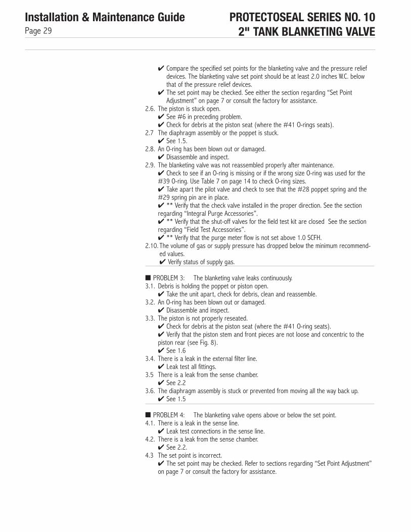
✔ Compare the specified set points for the blanketing valve and the pressure reliefdevices. The blanketing valve set point should be at least 2.0 inches W.C. belowthat of the pressure relief devices.
✔ The set point may be checked. See either the section regarding “Set PointAdjustment” on page 7 or consult the factory for assistance.
2.6. The piston is stuck open.✔ See #6 in preceding problem.✔ Check for debris at the piston seat (where the #41 O-rings seats).
2.7 The diaphragm assembly or the poppet is stuck.✔ See 1.5.
2.8. An O-ring has been blown out or damaged.✔ Disassemble and inspect.
2.9. The blanketing valve was not reassembled properly after maintenance.✔ Check to see if an O-ring is missing or if the wrong size O-ring was used for the#39 O-ring. Use Table 7 on page 14 to check O-ring sizes.✔ Take apart the pilot valve and check to see that the #28 poppet spring and the#29 spring pin are in place.✔ ** Verify that the check valve installed in the proper direction. See the sectionregarding “Integral Purge Accessories”.✔ ** Verify that the shut-off valves for the field test kit are closed See the sectionregarding “Field Test Accessories”.✔ ** Verify that the purge meter flow is not set above 1.0 SCFH.
2.10. The volume of gas or supply pressure has dropped below the minimum recommend-ed values.✔ Verify status of supply gas.
■ PROBLEM 3: The blanketing valve leaks continuously.3.1. Debris is holding the poppet or piston open.
✔ Take the unit apart, check for debris, clean and reassemble.3.2. An O-ring has been blown out or damaged.
✔ Disassemble and inspect.3.3. The piston is not properly reseated.
✔ Check for debris at the piston seat (where the #41 O-ring seats).✔ Verify that the piston stem and front pieces are not loose and concentric to thepiston rear (see Fig. 8).✔ See 1.6
3.4. There is a leak in the external filter line.✔ Leak test all fittings.
3.5 There is a leak from the sense chamber.✔ See 2.2
3.6. The diaphragm assembly is stuck or prevented from moving all the way back up.✔ See 1.5
■ PROBLEM 4: The blanketing valve opens above or below the set point.4.1. There is a leak in the sense line.
✔ Leak test connections in the sense line.4.2. There is a leak from the sense chamber.
✔ See 2.2.4.3 The set point is incorrect.
✔ The set point may be checked. Refer to sections regarding “Set Point Adjustment”on page 7 or consult the factory for assistance.

PROTECTOSEAL SERIES NO. 102" TANK BLANKETING VALVE
Installation & Maintenance GuidePage 30
■ PROBLEM 5: The pressure vent or other pressure relief device opens before the blanketing valve closes.5.1. The set point of the two devices are too close to each other
✔ See 2.4.5.2. The blanketing valve is opening above its set specified set point.
✔ Has the #2 set screw been adjusted? If the set screw has been screwed in thenthe opening pressure will have been raised.✔ The set point may be checked. Refer to sections regarding “Set Point
5.3. The pressure relief device is opening below its specified set point.✔ Check the opening pressure of the pressure relief device.
5.4. The blanketing valve is closing too far above its set point. This would indicate that the pilot valve is not functioning properly.✔ Check that the #32 lower plug assembly is screwed in all the way with the mark onthe nut lining up with the mark on the pilot body.✔ Check for debris in the pilot valve.✔ Inspect the O-rings in the pilot valve.✔ Possibly the pilot valve was not reassembled properly after maintenance.
5.5. The blanketing valve flow capacity is too high for the system.✔ Refer to the “User Guide” for assistance in determining flow capacity sizing.
■ PROBLEM 6: The vacuum vent or other vacuum relief device opens.6.1. The blanketing valve set point is below (more negative than) the vacuum vent set
point.✔ Check the labels of the blanketing valve and the vacuum relief device to identify theset points. The set point of one of the units may have to be changed.
6.2 The blanketing valve is opening below its set point.✔ See 1.4.
6.3. The vacuum vent is opening above its set point.✔ Check the opening pressure of the vacuum relief device.
6.4. The blanketing valve flow capacity is not high enough for the system.✔ Refer to the “User Guide” for assistance in determining flow capacity sizing.
■ PROBLEM 7: The blanketing valve cycles, repeatedly opening and closing.7.1. The blanketing valve flow capacity is too high for the system.
✔ Refer to the User’s Guide for assistance in determining flow capacity sizing.7.2 **The check valve in the line between the outlet and the purge meter is not sealing.
✔ Refer to the section on “Integral Purge Accessories” on page 18 for procedureson investigating the operation of the check valve. Replace the check valve if it is founddefective.
7.3 The pressure relief vent is set too close to the blanketing valve set point.✔ Check set points, one may need to be changed.
7.4 The outlet size of the blanketing valve is too small for the system.✔ Contact factory for additional help.
7.5 The sense line is located too close to the blanketing valve outlet.✔ Adjust location of sense line (see Fig. 2).
NOTE: ** Refers to optional equipment which may not be included with your unit.

V10/A The Protectoseal Company - 2016
®PROTECTOSEALSafety Without Compromise
The Protectoseal Company225 W. Foster AvenueBensenville, IL 60106
Phone: 630-595-0800Fax: 630-595-8059
www.protectoseal.com