Embed Size (px)
Citation preview

Installation & Maintenance Guide
PROTECTOSEAL SERIES NO. 20TANK BLANKETING VALVE
PROTECTOSEAL®
Safety Without Compromise
225 Foster Ave., Bensenville, IL 60106-1690P 630.595.0800 F [email protected] www.protectoseal.com

PROTECTOSEAL SERIES NO. 20TANK BLANKETING VALVE
Installation & Maintenance Guide
Definition of Terms Some of the terms used in this manual are defined below:Conservation Vent: A device which is connected to a storage tank and regulates thepressure therein. Conservation vents may provide pressure relief, vacuum relief, or both.Pallets move in direct response to tank pressure allowing flow out of or into the tank. Palletmovement may be controlled by weight-loading, spring-loading, or a pilot valve.Deadband: The total pressure difference between the blanketing valve opening pressure(or set point) and resealing pressure. This applies to the main valve; some leakage throughthe pilot will occur above the main valve reseating pressureDiaphragm Chamber: The portion of the pilot valve which contains the sensediaphragm.Dome Pressure: The pressure in the dome volume.Dome Volume: The chamber between the poppet in the pilot valve and the piston in themain valve.Emergency Vent: A conservation vent which provides additional pressure relief toaccommodate extraordinary conditions such as fire exposure to a tank or full-open failureof a blanketing valve.Flow Plug: A small cylinder which may be connected to the end of the piston to partiallyblock flow past the inlet seat of the main valve. This is used to reduce the blanketingvalve’s flow capacity.Inlet Port: The connection to the blanketing valve coming from the gas supply line.Main Valve: The portion of the blanketing valve through which the supply gas flows intothe storage tank.Orifice: A small diameter passage in the line between the inlet port and the dome volume.Outlet Port: The connection to the blanketing valve leading to the storage tank.Pilot Valve: The portion of the blanketing valve which senses the tank pressure and con-trols the dome pressure.Piston: The component in the main valve which moves open from a normally seated posi-tion to allow flow of blanketing gas through the valve.Piston Spring: The spring which biases the piston towards the seated position.Poppet: The component in the pilot valve which can move open from a normally seatedposition to allow flow through the valve.Poppet Spring: The spring which biases the poppet towards the seated position.Purge: A very low flow of supply gas directed past the sense line and/or the outlet inorder to keep corrosive vapors away from the blanketing valve.Sense Chamber: The space below the diaphragm chamber to which the pressure fromthe sense line is directed. The pressure in the sense chamber controls the opening andclosing of the pilot and blanketing valve.Sense Diaphragm: A thin, non-metallic disc in the diaphragm chamber which flexes inresponse to changes in tank pressure acting upon it.Sense Line: A line running from the storage tank to the sense port of the blanketingvalve. It feeds tank pressure to the underside of the sense diaphragm.Sense Port: The connection to the blanketing valve coming from the sense line.Set Point: The tank pressure (positive or negative) at which the blanketing valve opens.Soft Goods: The elastomeric components of the blanketing valve including the o-rings,gaskets and diaphragm.Stop: A bolt connected to the sense diaphragm which contacts the poppet to move it inresponse to movement of the sense diaphragm.
Viton® and Kalrez® are registered Trademarks of E.I. DuPont de Nemours & Co., Inc. Chemraz® is a registered Trademark of Green, Tweed& Co., Inc.

PROTECTOSEAL SERIES NO. 20TANK BLANKETING VALVE
Table of Contents
Installation, Start-up & Shut-DownPlacement . . . . . . . . . . . . . . . . . . . . . . . . . . . . . . . . . . . . . . . . . . . . . . . . . . 1Start-Up . . . . . . . . . . . . . . . . . . . . . . . . . . . . . . . . . . . . . . . . . . . . . . . . . . . 2Shut-Down . . . . . . . . . . . . . . . . . . . . . . . . . . . . . . . . . . . . . . . . . . . . . . . . . . 3
MaintenancePurpose & Frequency. . . . . . . . . . . . . . . . . . . . . . . . . . . . . . . . . . . . . . . . . . 3Leakage Check . . . . . . . . . . . . . . . . . . . . . . . . . . . . . . . . . . . . . . . . . . . . . . . 3Disassembly & Inspection . . . . . . . . . . . . . . . . . . . . . . . . . . . . . . . . . . . . . . . 3Reassembly . . . . . . . . . . . . . . . . . . . . . . . . . . . . . . . . . . . . . . . . . . . . . . . . . 5Reinstallation & System Check . . . . . . . . . . . . . . . . . . . . . . . . . . . . . . . . . . . 6
AccessoriesFilter. . . . . . . . . . . . . . . . . . . . . . . . . . . . . . . . . . . . . . . . . . . . . . . . . . . 14Check Valve . . . . . . . . . . . . . . . . . . . . . . . . . . . . . . . . . . . . . . . . . . . . . . . . 15Pressure Gauges . . . . . . . . . . . . . . . . . . . . . . . . . . . . . . . . . . . . . . . . . . . . 16Integral Purge Accessories. . . . . . . . . . . . . . . . . . . . . . . . . . . . . . . . . . . . . 16Field Test Accessories . . . . . . . . . . . . . . . . . . . . . . . . . . . . . . . . . . . . . . . . 19Combination of Accessories (Fig. 16) . . . . . . . . . . . . . . . . . . . . . . . . . . . . . 25
TroubleshootingProblem -#1 The blanketing valve does not open at all . . . . . . . . . . . . . . . . . . . . . 26#2 The blanketing valve flows full open without resealing . . . . . . . . . . . . 26#3 The blanketing valve leaks continuously. . . . . . . . . . . . . . . . . . . . . . . . 27#4 The blanketing valve opens above or below the set point. . . . . . . . . . 27#5 The pressure vent or other pressure relief device opens . . . . . . . . . . 27
before the blanketing valve closes#6 The vacuum vent or other vacuum relief device opens . . . . . . . . . . . . 28#7 The blanketing valve cycles, repeatedly opening and . . . . . . . . . . . . . 28
closing
Figures#1 Installation . . . . . . . . . . . . . . . . . . . . . . . . . . . . . . . . . . . . . . . . . . 1#2 Recommended Minimum Sense Line I.D. Based on Length . . . . . . . . . . 2#3 Bolt Tightening Pattern. . . . . . . . . . . . . . . . . . . . . . . . . . . . . . . . . . . . . 6#4 Blanketing Valve . . . . . . . . . . . . . . . . . . . . . . . . . . . . . . . . . . . . . . . . . . 7#5 Diaphragm Assembly . . . . . . . . . . . . . . . . . . . . . . . . . . . . . . . . . . . . . . 8#6 Pilot Valve Assembly . . . . . . . . . . . . . . . . . . . . . . . . . . . . . . . . . . . . . . . 9#7 Main Valve Assembly . . . . . . . . . . . . . . . . . . . . . . . . . . . . . . . . . . . . . 10
#8 Piston Assembly . . . . . . . . . . . . . . . . . . . . . . . . . . . . . . . . . . . . . . . . . . . . . 11#9 Recommended Test Set-Up. . . . . . . . . . . . . . . . . . . . . . . . . . . . . . . . . 13#10 Pilot Filter. . . . . . . . . . . . . . . . . . . . . . . . . . . . . . . . . . . . . . . . . . . . . . 14
#11Check Valve Location . . . . . . . . . . . . . . . . . . . . . . . . . . . . . . . . . . . . . . . . . 15#12 Pressure Gauge s . . . . . . . . . . . . . . . . . . . . . . . . . . . . . . . . . . . . . . . . 16#13 Integral Purge System . . . . . . . . . . . . . . . . . . . . . . . . . . . . . . . . . . . . 17#14Higher Pressure Set Point Field Test Kit . . . . . . . . . . . . . . . . . . . . . . . 23#15 Low Pressure or Vacuum Set Point Field Test Kit . . . . . . . . . . . . . . . . 24#16 Combination of all Available Accessories . . . . . . . . . . . . . . . . . . . . . . . 25

PROTECTOSEAL SERIES NO. 20TANK BLANKETING VALVE
Installation & Maintenance GuidePage 1
Placement
INSTALLATION
The blanketing valve should be placed on top of the storage tank with its outlet connected viaa short run of pipe to the top of the tank. A second, usually smaller, line runs from thesense port of the valve to a separate connection on the tank. A line coming from the blan-keting gas supply source connects to the valve inlet. The blanketing valve must be posi-tioned so that the inlet line is horizontal and the outlet line points downward. Installationrequires connecting the blanketing valve to three lines as shown below in Fig. 1.
Fig. 1
All three lines connecting to the valve should have full bore shut-off valves so that the unitcan be isolated and depressurized for maintenance. The use of pipe unions at each con-nection will facilitate installation and removal of the blanketing valve. FEP tape should beapplied to all pipe thread connections. However, be careful in applying it so that the tapecannot get loose inside and potentially clog the blanketing valve. DO NOT USE PIPE DOPE.Further details regarding the three lines follow:
■ SUPPLY LINE: The piping leading to the blanketing valve inlet should be the same pipesize as the inlet connection. This line should incorporate a full bore shut-off valve to enableisolation of the valve from the pressure supply during maintenance. The line should alsoinclude an in-line filter. A 5 to 40 micron filter element is recommended. The filter flowcapacity must be higher than the required flow through the blanketing valve.
■ OUTLET LINE: The piping from the valve outlet should be the same size as the outletconnection. This line should also incorporate a full bore-shut-off valve to enable isolation ofthe blanketing valve from the tank during maintenance. A short, straight pipe run from thevalve outlet to the top of the storage tank is recommended. An extended length of pipefrom the blanketing valve to the tank could lead to delayed closing of the valve and thusoverpressurization of the tank.
■ SENSE LINE: The sense line should also include a full bore valve to enable isolation ofthe blanketing valve from the tank during maintenance. The horizontal run from the senseport should be angled slightly down away from the valve to ensure that any

Start-Up
PROTECTOSEAL SERIES NO. 20TANK BLANKETING VALVE
condensate could not drain into the valve. 1⁄2" O.D. tubing or larger should be used toensure that there is not a pressure drop from the tank to the valve. This size line is alsoneeded so that the high pressure supply gas which leaks into the sense chamber while thevalve is open is able to dissipate into the tank so as not to affect closing of the blanketingvalve.
The sense line connection to the tank should be far enough from the outlet line connectionto ensure that a static pressure is sensed. On the other hand, the line should not be solong as to lead to a pressure drop in the line. A range of 2 to 10 feet from the outlet lineconnection is recommended. If a longer sense line is necessary, then the size of the tubingor pipe should be increased according to offset pressure drop effects, see Fig. 2.
Installation & Maintenance GuidePage 2
Sense Line Length * (ft.), For 90° bends add 20 diameters to the length.
Fig. 2Recommended Minimum Sense Line I.D. Based on Length
The blanketing valve is tested and set to the customer specified set point (as listed on thelabel) prior to shipment. After installation is complete, follow the steps below in order to putthe blanketing valve into service:
1. Open the shut-off valve in the sense line between the blanketing valve and the tank.2. Open the shut-off valve in the outlet line between the blanketing valve and the tank.3. Check the blanketing gas supply line pressure to see that it corresponds to the
pressure or pressure range listed on the label of the blanketing valve. If not, the sup-ply pressure regulator should be adjusted accordingly. The maximum range in which the valve will operate is 20 to 200 PSIG.
4. Slowly open the shut-off valve in the blanketing gas supply line. Pressurizing the blanketing valve slowly pre-loads the valve so that it will not initially pop open.
If the tank pressure is above the blanketing valve set point, then the blanketing valveshould seal immediately. Otherwise the valve will open and flow until the tank pressure risesabove the set point. If the blanketing valve does not reseal at all, consult “Troubleshooting”on page 26.

Shut-Down
Purpose & Frequency
Leakage Check
Disassembly &Inspection
The blanketing valve must be depressurized when removing it from operation. Follow thesteps below for system shut-down:
1. Close the shut-off valve in the blanketing gas supply line.2. Close the shut-off valve in the sense line.3. Pressure between the supply line shut-off and the seals inside the blanketing valve
must be bled off. If the set point pressure is above atmospheric pressure, then thesafest way to do this is to break the seal at the sense port of the blanketing valve.This will allow the pressure in the sense chamber to drop which will open the blanket-ing valve and bleed off the internal pressure into the tank. If the blanketing valve hasa setting below atmospheric pressure, then a different method must be used. In addi-tion to cracking the sense line, a connection between the supply line shut-off valveand the blanketing valve inlet port must be cracked to allow the high pressure gas tobleed out. The connection should be cracked slowly so that the high pressure gasbleeds, not bursts, out.
4. Close the shut-off valve in the outlet line.5. Remove the supply line to the blanketing valve carefully in case there is still trapped
pressure in the line.
Periodic maintenance checks are recommended to ensure that the blanketing valve is ingood operating condition. Debris in the valve or damaged seals are the most likely causes ofoperating problems. The frequency of routine maintenance necessary for the blanketingvalve will depend on the severity of the operating conditions. The valve should be checkedwithin a month of installation and then as determined appropriate after that. At minimum,the valve should be checked annually.
Before performing any disassembly, it is a good idea to check for external leakage. This canbe done by spraying or brushing soap around mating connections and bolts. If no leakageis detected around the #12 gasket or the #15 gasket (See Fig. 4), then it should not benecessary to disassemble the diaphragm case while performing routine maintenance.
The following instructions are for maintenance of the standard components of the blanket-ing valve. Refer to the section entitled “Accessory Equipment” for instructions regardingoptional accessories. Also, the diagrams in this section show a unit with standard 1" FNPTinlet and outlet connections. Except where noted, these instructions apply also to units withother inlet and outlet connections.
Protectoseal O-rings and gaskets are available from Protectoseal. See Table 6 on page 12for soft goods kits which can be ordered.
CAUTION: The blanketing valve must be completely depressurized before any disassemblyis performed. See the “shut-down” instructions above.
PROTECTOSEAL SERIES NO. 20TANK BLANKETING VALVE
Installation/Maintenance GuidePage 3
MAINTENANCE

PROTECTOSEAL SERIES NO. 20TANK BLANKETING VALVE
Installation & Maintenance GuidePage 4
■ DIAPHRAGM CASE (See Fig. 4)Remove the eight (8), #11 bolts, #13 nuts, and #4 lock washers. Carefully pull up theupper case assembly. Reach under the case to hold the #6 set spring in position whilepulling the case up so that the spring and the #5 upper anchor do not fall over. The #9diaphragm assembly and the #12 gasket can now be removed and checked. If there is anycorrosion or damage to the gasket, it must be replaced.
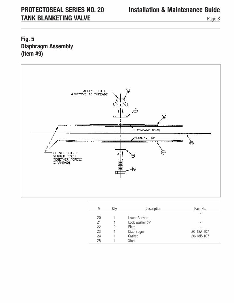
Looking at the diaphragm assembly, the two (2), #22 plates should be clamped flatagainst the #23 diaphragm, and the diaphragm should be free of cracks, cuts or holes.See Fig. 5 for disassembly of the diaphragm assembly. Unthread the #25 stop (machinedhex screw) from the #20 lower anchor. Note: This connection may be very tight due tothread adhesive being applied during assembly. The diaphragm and the #24 gasket shouldbe free of cracks, cuts or holes. To remove the #14 lower case, remove the four (4), #7hex screws. This exposes the #15 gasket which can then be inspected for corrosion ordamage.
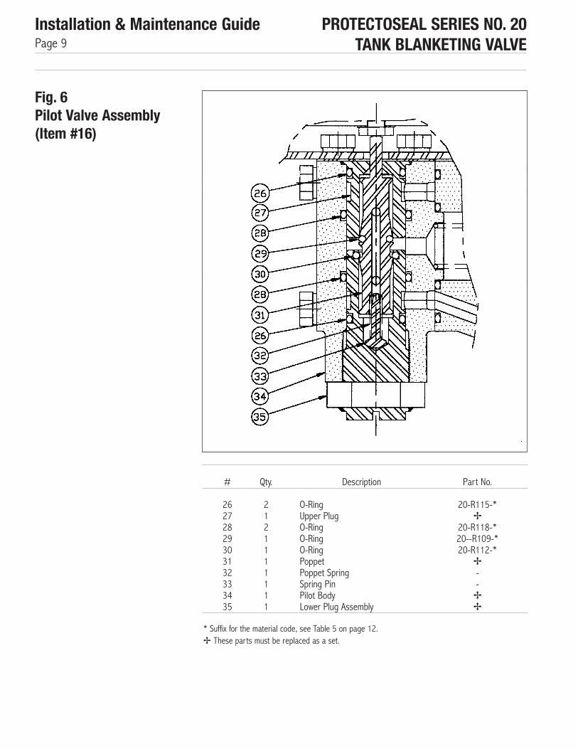
■ PILOT VALVE (See Figs. 6 & 7)Position the blanketing valve so that the inlet points downward. Remove the four (4), #17hex screws. Slowly lift up and remove the pilot body. Set aside the #18 main valve including(Fig. 7) the #39 piston spring, #36 O-ring and #37 O-ring.
Refer to Fig. 6.Before removing the #35 lower plug assembly, identify the marks on the nutof the lower plug assembly and the bottom of the pilot body. These marks, which should belined up with each other, identify the proper position of the lower plug. This position is setat the factory for optimal performance of the blanketing valve. If the marks are not easy tosee, then additional marks to identify the position during reassembly (with felt tip pen orotherwise) should be made on the nut and the pilot body before unscrewing the lower plug.Unscrew and remove the #35 lower plug assembly. When this is removed, the #31 poppetand attached parts will come out with it. Be careful not to damage the fine thread on thelower plug after removal.
Grasping the lower plug assembly in one hand and the poppet in the other, firmly tug onthe poppet to pull it out of the lower plug assembly. Be certain to do this in a slow, con-trolled manner so that the #32 poppet spring does not fly out and get lost. If the #14lower case has been removed, then the #27 upper plug can also be removed. The bestway to do this is to slowly insert a phillips-head screwdriver up into the bottom of the smallhole in the upper plug and tap on it to push the plug out. Be very careful not to damagethe inside bottom of the upper plug where the #29 O-ring seats. The O-rings can now beinspected for wear or corrosion.
■ MAIN VALVE (See Figs 7 & 8)The #36 and #37 O-rings which were between the main body and the pilot body may beinspected for corrosion or damage. Slide the #40 piston out of the #38 main body. Inspectthe #46 and #47 O-rings for wear or corrosion. Remove the #49 or #52 hex screw todisassemble the piston assembly. A thin open end wrench must be slid across the flats onthe piston to secure it while removing the screw. Be careful not to damage the outside ofthe piston or create any burrs along side the wrench flats.
It may be possible to inspect the #42 screen assembly while it is in the #41 inlet cap.Alternately, or if it needs to be cleaned, it can be removed by sliding a special tool into theslots in the collar of the screen assembly and unscrewing it. Contact your SalesRepresentative and request Part No. 20-T1A for the necessary tool. For a unit with a 1⁄2"FNPT or 3⁄4" FNPT inlet, the thread adapter must be unscrewed and removed in order totake out the screen assembly. Note: If the unit as a 1⁄2" or 3⁄4" inlet flange, a different toolalong with special instructions will be required.

PROTECTOSEAL SERIES NO. 20TANK BLANKETING VALVE
Installation & Maintenance GuidePage 5
If no leakage between the main body and the inlet cap was detected during the leakagetest, then it will not be necessary to remove the inlet cap. If it is desired to remove the inletcap, first remove the #44 tube by loosening the nuts on each end. Then (See Fig. 4)remove the four (4), #19 hex screws and pull the inlet cap out from the main body. Thesecond #37 O-ring may then be inspected for corrosion or damage. If leakage was detect-ed at any connections in the external filter line (going through the #43 filter), then thesecomponents should be removed for inspection and reapplication of FEP tape on thetapered threads. Refer to page 14 for instructions on cleaning the filter.
When reassembling the blanketing valve, be sure to replace any worn or damaged O-ringsand gaskets.
■ MAIN VALVE (See Fig. 4, 7 & 8)Reinsert the #42 screen assembly into the #41 inlet cap if it was removed. If the inlet caphas been removed, then replace the #37 O-ring, insert the inlet cap into the #18 mainbody, and secure it with the four (4), #19 hex screws and lock washers. Tighten thescrews to 96 in-lbs.
Reassemble any connections which were loosened in the external filter line. Apply FEP tapeto any tapered thread connection. Reconnect the #44 tube by attaching and tightening thetwo (2) nuts.
Before reassembling the #40 piston assembly (see Fig. 8), the #46 and #47 O-ringsshould be lubricated. Recommended lubricants are DuPont Krytox GPL206 or Dow Corning111 Valve Lubricant, but any seal lubricant which is compatible with both the stored chemi-cal and the O-ring material may be appropriate. When reinserting the O-rings, be certainthat the larger of the two goes in the groove on the outside center of the piston (see Table7 on page 13 to check O-ring sizes). Reassemble the #48 retainer and, if included, the#51 flow plug. Insert the #49 or #52 hex screw with lock washer and tighten to 60 in-lbs.Push the piston assembly back into the main body. It should move freely in and out of thebore but should not drop through freely. If it does drop through, the wrong size (too small)O-ring must have been put into the outside center groove.
■ PILOT VALVE (See Fig. 6)Before reassembling the pilot valve, the #29 and #30 O-rings should be lubricated.Reinsert all six (6) O-rings. It is also recommended that a conservative amount of anti-seize compound be applied to the threads of the lower plug before threading it back intothe pilot body. Hold the poppet upside down, insert the #32 poppet spring in the groove inthe end, and insert the #33 spring pin into the spring. Slide the #35 lower plug assemblyover the spring pin, spring, and poppet, and pop it into place. The poppet should moveeasily up and down inside the lower plug, being pushed up by the poppet spring. Push the#27 upper plug back into the #34 pilot body if it has been removed. The orientation of thecross holes in the upper plug is not important. Slowly, being careful not to damage the endof the stem on the poppet or the seat at the end of the piston, insert the #36 and #37 O-rings into the grooves in the main body. Carefully position the pilot body over the main bodyso that the piston spring fits into the groove in the pilot body. Slowly push the pilot bodytoward the main body so that the hub of the pilot body slides inside the #36 O-ring. BEVERY CAREFUL NOT TO CUT OR DAMAGE THE O-RING! While holding the pilot body in place,insert the four (4), #17 hex screws with lock washers and tighten to 96 in-lbs.
Reassembly
■ DIAPHRAGM CASE (See Fig. 4)With the assembly of bodies upright, place the #15 gasket on top of the pilot body. Placethe #14 lower case over the gasket and secure it with four (4), #7 hex screws and lockwashers, tightening to 96 in-lbs. If the #9 diaphragm assembly has been disassembled,then reassemble it as shown in Fig. 5. Apply thread adhesive to the thread connection andtighten until lock washer and plates are compressed.
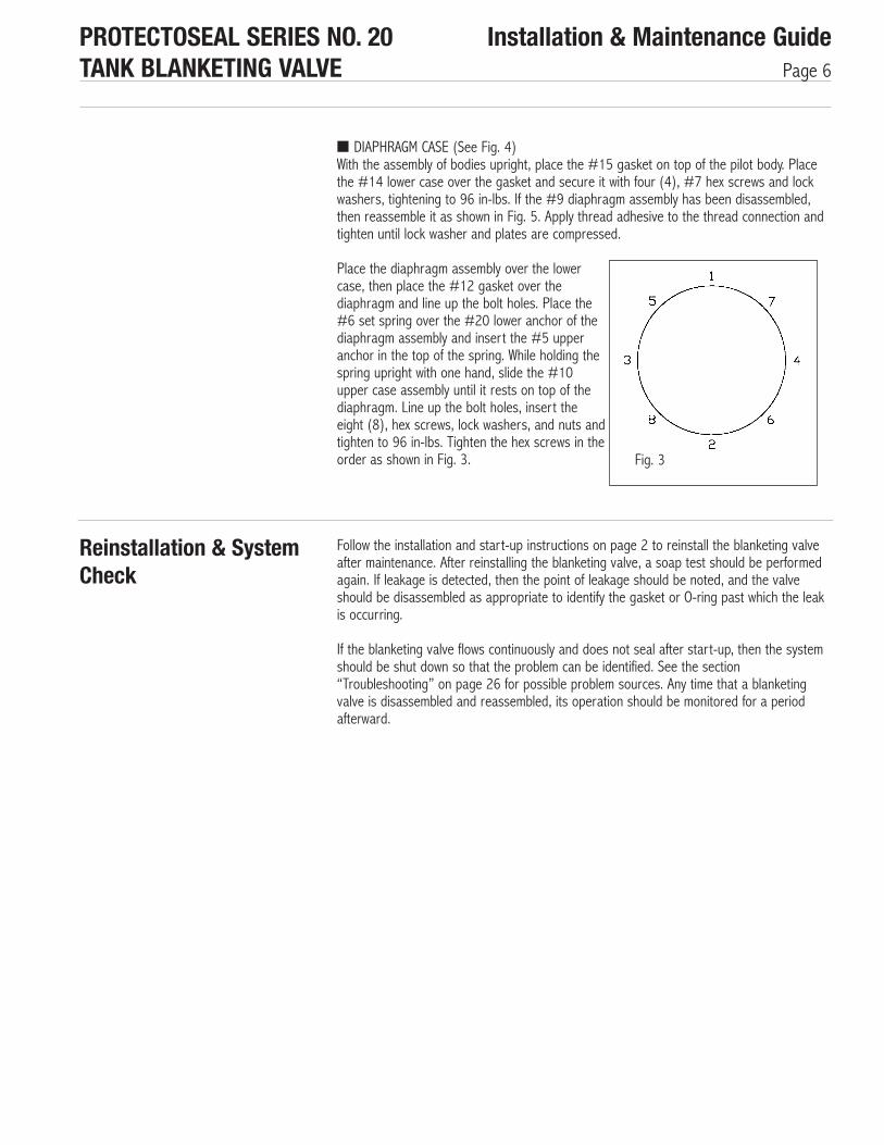
Place the diaphragm assembly over the lowercase, then place the #12 gasket over thediaphragm and line up the bolt holes. Place the#6 set spring over the #20 lower anchor of thediaphragm assembly and insert the #5 upperanchor in the top of the spring. While holding thespring upright with one hand, slide the #10upper case assembly until it rests on top of thediaphragm. Line up the bolt holes, insert theeight (8), hex screws, lock washers, and nuts andtighten to 96 in-lbs. Tighten the hex screws in theorder as shown in Fig. 3.
PROTECTOSEAL SERIES NO. 20TANK BLANKETING VALVE
Installation & Maintenance GuidePage 6
Reinstallation & SystemCheck
Follow the installation and start-up instructions on page 2 to reinstall the blanketing valveafter maintenance. After reinstalling the blanketing valve, a soap test should be performedagain. If leakage is detected, then the point of leakage should be noted, and the valveshould be disassembled as appropriate to identify the gasket or O-ring past which the leakis occurring.
If the blanketing valve flows continuously and does not seal after start-up, then the systemshould be shut down so that the problem can be identified. See the section“Troubleshooting” on page 26 for possible problem sources. Any time that a blanketingvalve is disassembled and reassembled, its operation should be monitored for a periodafterward.
Fig. 3

PROTECTOSEAL SERIES NO. 20TANK BLANKETING VALVE
Installation & Maintenance GuidePage 7
Fig. 4Blanketing Valve
#
12345678910
Qty.
11191141211
#
11121314151617181920
Qty.
8181114141
Part No.
-20-18C-*
--
20-18D-*----
20-18E-*
Description
CapSet ScrewJam Nut, 3⁄8 - 24 UNFLock Washer, 3⁄8"Upper AnchorSet SpringHex Screw, 1/4 - 20 UNC x 1⁄2
Lock Washer, 1⁄4"Diaphragm Assembly (Fig. 5)Upper Case Assembly
Description
Hex Screw, 3⁄8 - 16 UNC x 3⁄4
GasketJam Nut, 3⁄8 - 16 UNCLower CaseGasketPilot Valve (Fig. 6)Hex Screw, 1⁄4 - 20 UNC x 2 1⁄4
Main Valve (Fig. 7)Hex Screw, 1⁄4 - 20 UNC x 1Gasket
* Suffix for the material code, see Table 5 on page 12.
PROTECTOSEAL SERIES NO. 20TANK BLANKETING VALVE
Installation & Maintenance GuidePage 8
Fig. 5Diaphragm Assembly(Item #9)
#
202122232425
Qty.
112111
Part No.----
20-18A-10720-18B-107
-
Description
Lower AnchorLock Washer 1⁄4"PlateDiaphragmGasketStop
PROTECTOSEAL SERIES NO. 20TANK BLANKETING VALVE
Installation & Maintenance GuidePage 9
Fig. 6Pilot Valve Assembly(Item #16)
#
26272829303132333435
Qty.
2121111111
Part No.
20-R115-*✢
20-R118-*20--R109-*20-R112-*
✢--✢✢
Description
O-RingUpper PlugO-RingO-RingO-RingPoppetPoppet SpringSpring PinPilot BodyLower Plug Assembly
* Suffix for the material code, see Table 5 on page 12.✢ These parts must be replaced as a set.

PROTECTOSEAL SERIES NO. 20TANK BLANKETING VALVE
Installation & Maintenance GuidePage 10
Fig. 7Main Valve Assembly(Item #18)
#
363738394041424344
Qty.
121111111
Part No.
20-R-121-*20-R137-*
-------
Description
O-RingO-RingMain BodyPiston SpringPiston Assembly (Fig. 8)Inlet CapScreen AssemblyPilot FilterTube
* Suffix for the material code, see Table 5 on page 12.

PROTECTOSEAL SERIES NO. 20TANK BLANKETING VALVE
Installation & Maintenance GuidePage 11
Fig 8Piston Assembly(Item #40)
#
4546474849505152
Qty.
11111111
Part No.-
20-R117-*20-R116-*
-----
Description
PistonO-Ring (larger)O-Ring (smaller)RetainerHex Screw, 1⁄4 - 20 UNC x 1⁄2Lock Washer, 1⁄4"Flow PlugHex Screw, 1⁄4 - 20 UNC x 7⁄8
* Suffix for the material code, see Table 5 on page 12.
PROTECTOSEAL SERIES NO. 20TANK BLANKETING VALVE
Installation & Maintenance GuidePage 12
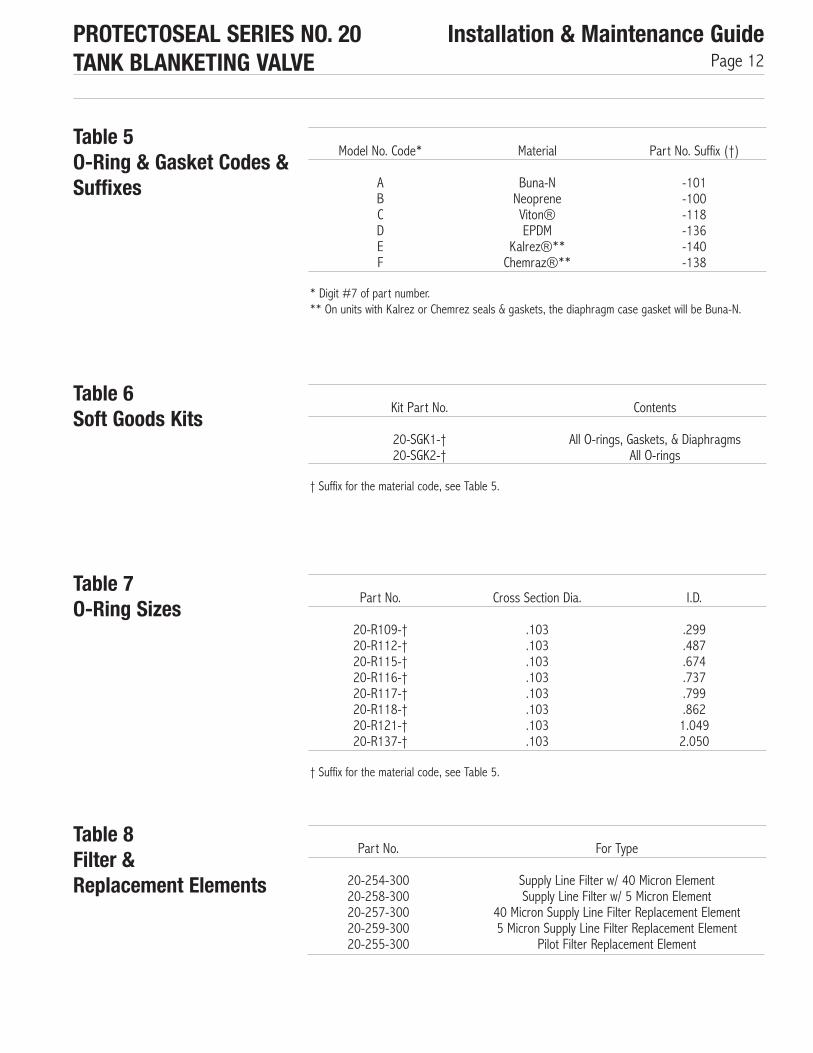
Table 5O-Ring & Gasket Codes &Suffixes
Table 6Soft Goods Kits
Table 7O-Ring Sizes
Model No. Code*
ABCDEF
Material
Buna-NNeopreneViton®EPDM
Kalrez®**Chemraz®**
Part No. Suffix (†)
-101-100-118-136-140-138
Part No.
20-R109-†20-R112-†20-R115-†20-R116-†20-R117-†20-R118-†20-R121-†20-R137-†
Cross Section Dia.
.103
.103
.103
.103
.103
.103
.103
.103
I.D.
.299
.487
.674
.737
.799
.8621.0492.050
† Suffix for the material code, see Table 5.
† Suffix for the material code, see Table 5.
* Digit #7 of part number.** On units with Kalrez or Chemrez seals & gaskets, the diaphragm case gasket will be Buna-N.
Kit Part No.
20-SGK1-†20-SGK2-†
Contents
All O-rings, Gaskets, & DiaphragmsAll O-rings
Table 8Filter & Replacement Elements
Part No.
20-254-30020-258-30020-257-30020-259-30020-255-300
For Type
Supply Line Filter w/ 40 Micron ElementSupply Line Filter w/ 5 Micron Element
40 Micron Supply Line Filter Replacement Element5 Micron Supply Line Filter Replacement Element
Pilot Filter Replacement Element
PROTECTOSEAL SERIES NO. 20TANK BLANKETING VALVE
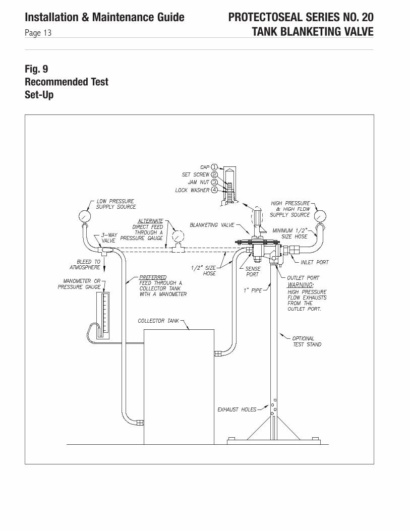
Installation & Maintenance GuidePage 13
Fig. 9Recommended TestSet-Up
PROTECTOSEAL SERIES NO. 20TANK BLANKETING VALVE
Installation & Maintenance GuidePage 14
Filter
ACCESSORIES
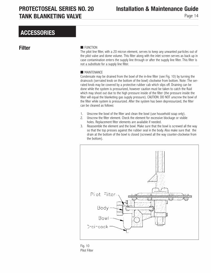
Fig. 10Pilot Filter
■ FUNCTIONThe pilot line filter, with a 20 micron element, serves to keep any unwanted particles out ofthe pilot valve and dome volume. This filter along with the inlet screen serves as back up incase contamination enters the supply line through or after the supply line filter. This filter isnot a substitute for a supply line filter.
■ MAINTENANCECondensate may be drained from the bowl of the in-line filter (see Fig. 10) by turning thedraincock (serrated knob on the bottom of the bowl) clockwise from bottom. Note: The ser-rated knob may be covered by a protective rubber cab which slips off. Draining can bedone while the system is pressurized, however caution must be taken to catch the fluidwhich may shoot out due to the high pressure inside of the filter (the pressure inside thefilter will equal the blanketing gas supply pressure). CAUTION: DO NOT unscrew the bowl ofthe filter while system is pressurized. After the system has been depressurized, the filtercan be cleaned as follows:
1. Unscrew the bowl of the filter and clean the bowl (use household soap only).2. Unscrew the filter element. Check the element for excessive blockage or visible
holes. Replacement filter elements are available if needed.3. Reassemble the element and the bowl. Make sure that the bowl is screwed all the way
so that the top presses against the rubber seal in the body. Also make sure that thedrain at the bottom of the bowl is closed (screwed all the way counter-clockwise fromthe bottom).

PROTECTOSEAL SERIES NO. 20TANK BLANKETING VALVE
Installation & Maintenance GuidePage 15
Check Valve ■ FUNCTIONThe check valve, which goes in the external filter line between the inlet gas supply and thepilot valve, prevents tank pressure from being drawn out of the tank through the blanketingvalve in the event that pressure in the blanketing gas supply line should drop to zero orvacuum. It is in between the inlet cap and the pilot filter and allows flow in only one direc-tion - from the inlet to the filter (and on to the pilot). See Fig. 11.
■ MAINTENANCEThe check valve should not normally require maintenance. When the blanketing valve hasbeen depressurized, the check valve may be removed and checked. A small arrow on thebody of the check valve shows the direction in which flow is allowed. If pressure is suppliedto the inlet, flow should come through the outlet. If pressure is supplied at the outlet, noflow should pass through the check valve. If the check valve is found to be defective, itmust be replaced.
When installing the check valve, be certain that it is positioned with the arrow pointing awayfrom the inlet (in the direction of flow shown in Fig. 11).
Fig. 11Check Valve Location

PROTECTOSEAL SERIES NO. 20TANK BLANKETING VALVE
Installation & Maintenance GuidePage 16
Pressure Gauges ■ FUNCTIONOptional pressure gauges may be included which enable system pressure monitoring. Thesupply line pressure gauge will show the blanketing gas supply pressure at the inlet to andinside of the blanketing valve. The sense line pressure gauge will show the tank pressurebeing sensed by the blanketing valve through the sense line.
■ MAINTENANCEWhen the blanketing valve has been completely depressurized, gauges may be removed forcalibration checks. Replacement gauges can be ordered if necessary. The sense line gaugesupplied by Protectoseal has a working pressure of up to 15 psig and so should not bedamaged by fluctuations in tank pressure. Damage to the supply pressure gauge may indi-cate that the blanketing gas supply system was overpressurized at some point. Excessivesupply pressure can cause blanketing valve failure and should be immediately investigated.
Fig. 12Pressure Gauges
Integral PurgeAccessories
■ FUNCTIONThe integral purge is used to create a small flow of blanketing gas at the blanketing valveoutlet and/or the sense line connection in order to keep vapors from the material stored inthe tank from corroding the blanketing valve. Due to the blanketing valve’s stainless steel316 construction, the availability of chemically resistant soft goods, and the high concentra-tion of blanketing gas present in the blanketing valve, the integral purge should not be nec-essary except in very severe service conditions. Both the blanketing valve

Fig. 13Integral Purge System with Outlet & Sense Line Purges
PROTECTOSEAL SERIES NO. 20TANK BLANKETING VALVE
Installation & Maintenance GuidePage 17
outlet, and to a much lesser extent, the sense line will be purged with blanketing gas anytime that the blanketing valve opens. The integral purge, however, flows continuously andso also lessens the existence of standing vapors from the stored material when the blan-keting valve is closed.
■ OPERATIONThe integral purge system uses the blanketing gas supply to create a trickle of flow at theoutlet port and/or sense port. The purge meter (See Fig. 13) is used to control the flowgoing to either of these locations. A recommended flow through the meter is 0.5 SCFH.Flows higher than about 1.0 SCFH past the sense port are not recommended because theycan create an artificially high pressure at the sense port leading to the valve opening at atank pressure lower than the set point. If the purge is only to the outlet line, then higherflows create only the problem of high supply gas usage.
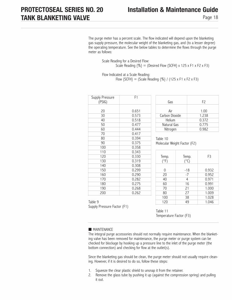
Temp.(°F)
02040607080100120
Temp.(°C)
-18-741621273849
F3
0.9320.9520.9710.9911.0001.0091.0281.046
The purge meter has a percent scale. The flow indicated will depend upon the blanketinggas supply pressure, the molecular weight of the blanketing gas, and (to a lesser degree)the operating temperature. See the below tables to determine the flows through the purgemeter as follows:
Scale Reading for a Desired Flow:Scale Reading {%} = (Desired Flow {SCFH} x 125 x F1 x F2 x F3)
Flow Indicated at a Scale Reading:Flow {SCFH} = (Scale Reading {%} / (125 x F1 x F2 x F3)
PROTECTOSEAL SERIES NO. 20TANK BLANKETING VALVE
Installation & Maintenance GuidePage 18
Supply Pressure(PSIG)
2030405060708090100110120130140150160170180190200
F1
0.6510.5730.5180.4770.4440.4170.3940.3750.3580.3430.3300.3190.3080.2990.2900.2820.2750.2680.262
Gas
AirCarbon Dioxide
HeliumNatural GasNitrogen
F2
1.001.2380.3720.7750.982
Table 10Molecular Weight Factor (F2)
Table 11Temperature Factor (F3)
Table 9Supply Pressure Factor (F1)
■ MAINTENANCEThe integral purge accessories should not normally require maintenance. When the blanket-ing valve has been removed for maintenance, the purge meter or purge system can bechecked for blockage by hooking up a pressure line to the inlet of the purge meter (thebottom connection) and checking for flow at the outlet(s).
Since the blanketing gas should be clean, the purge meter should not usually require clean-ing. However, if it is desired to do so, follow these steps:
1. Squeeze the clear plastic shield to unsnap it from the retainer.2. Remove the glass tube by pushing it up (against the compression spring) and pulling
it out.
3. Use tweezers to pull the float stop out from the top of the tube and then carefully tiltthe tube to remove the float. Handle the float with care to avoid nicking or scratching it.
4. Clean the tube and float with mild detergent and water or with a suitable solvent. Usea soft cloth or tube brush to clean the meter tube. Do not expose the tube or float toextreme temperature changes.
5. The shield may be cleaned with detergent and water or with kerosine. If kerosine isused, follow up cleaning with detergent and water.
6. Reassemble in the reverse order of disassembly.
Units which have an outlet line purge will include one or more check valves which preventback flow from the outlet when the blanketing valve opens. The blanketing valve will notfunction without these check valves. If it is desired to inspect these check valves, refer tothe paragraph on check valve maintenance. Be certain to note the direction of the arrowson the check valves before removing them so that they will be reinstalled properly (thearrows should point away from the purge meter as shown in Fig. 13.).
PROTECTOSEAL SERIES NO. 20TANK BLANKETING VALVE
Installation & Maintenance GuidePage 19
Field Test Accessories ■ FUNCTIONThe field test accessories make it possible to check the opening pressure of the valve inthe field. Through a series of valves and a regulator, the blanketing gas supply is regulateddown and directed into the sense chamber of the blanketing valve. A vacuum pump is alsoused in the low pressure / vacuum set point version in order to lower the pressure suffi-ciently. By lowering and raising this regulated pressure, the opening and closing point ofthe blanketing valve can be determined. Both the supply pressure gauge and the sensepressure gauge are included with the field test accessories.
Optional additional accessories are a 3-way valve for the outlet line and/or shut-off valvefor the sense line. The 3-way valve makes it possible to divert outlet flow away from thetank if the blanketing valve is field tested while connected to the system. The auxiliary outletport of the 3-way valve can either be connected to a collector or open directly to atmos-phere. The sense line shut-off valve is used to isolate the sense chamber while conductinga field test. It provides easy accessibility if the valve is field tested while connected to thetank. It also provides a quick means of sealing off the sense port if the valve is removedfrom the tank for testing.
■ SET-UPIf the unit has been removed from the system:
1. Seal off the sense port by closing the sense line shut-off valve or inserting a pipeplug.
2. Position the outlet of the valve so that the high pressure flow can exhaust safely. Theblanketing valve should be held securely by clamping or other means.
3. Connect a line from a pressure source to the valve inlet. The minimum restriction inthis line should be a 1⁄2" pipe size diameter. The pressure source must be of sufficientcapacity to open the blanketing valve fully, otherwise the valve will not operate consis-tently. Where possible, the inlet supply pressure should be equivalent to the blanketinggas supply pressure.
If the unit is still connected in the system:
1. Shut-off the blanketing gas supply to the inlet port.2. Isolate the sense port from the tank by closing the sense line shut-off valve.

PROTECTOSEAL SERIES NO. 20TANK BLANKETING VALVE
Installation & Maintenance GuidePage 20
03. If the unit has a 3-way valve, turn the handle on the valve approximately 180° toclose off the path to the tank and open up the blanketing valve outlet to the auxiliaryport.
04. If the unit does not have a 3-way valve, you must leave the outlet line open andexhaust the blanketing valve into the tank. CAUTION: Exhausting into the tank whilerunning a field test may cause the tank’s pressure relief vents to open.
Notes regarding the set point and valve operation:01. The set point of the Protectoseal Series 20 Blanketing Valve is specified as the pres-
sure at which the main valve opens.02. The opening of the main valve should be audibly distinguished from the opening of the
pilot valve. The pilot valve will begin to leak at a pressure just above that at which themain valve will open abruptly. The quick opening of the main valve is usually very loud,although the degree of loudness will depend upon the inlet pressure and the flowcapacity.
03. The main valve reseals above the pressure at which it opens, and the pilot resealsabove where the main valve reseals.
■ TESTING - HIGHER PRESSURE SET POINT KITIf the unit has set point range B, C, D or E (as indicated by digit 6 of the model number)(2.1 to 69.2 inches W.C.) then this section applies. If the unit has a set point range of A orF, then proceed to the next section entitled “Testing - Low Pressure or Vacuum Set Point”.
Follow these steps to determine the opening and resealing points (See Fig. 14):01. Connect the test kit as shown at connection #1 and connection #2 (if it is not already
attached). If the blanketing valve includes the integral purge option, the purge metershould be shut before using the field test unit.
02. Pull up the handle on the regulator to unlock it and turn the handle all the waycounter-clockwise. This minimizes the outlet pressure of the regulator so that the reg-ulator pressure gauge will not be damaged when inlet pressure is applied.
03. Turn the knobs on the needle valve and the bleed valve clockwise to close them.04. Open shut-off valve #2 (at the hose end of the test kit).05. CAUTION: Put on ear protection. The flow out of the valve can be extremely loud.06. Pressurize the inlet to the blanketing valve.07. Slowly open shut-off valve #1 (at the inlet of the test kit).08. Turn the handle on the regulator clockwise to increase the outlet pressure until the
regulator gauge reads approximately 10 PSIG.09. Slowly open the needle valve to pressurize the sense line. Bring the pressure up
above the set point (as indicated by the sense line pressure gauge).10. Lower the sensed pressure by adjusting the knobs on the bleed valve, the needle
valve and the regulator.11. Note: If the blanketing valve has been removed from the system, then pressure in the
sense chamber will bleed to atmosphere through the outlet port. Thus, there will notbe a tight system and some gas must be continually bled in through the test kit inorder to maintain the pressure at the sense port.
12. Cycle the sensed pressure up and down to determine the opening pressures. If theblanketing valve is not opening at the set point, CONSULT THE FACTORY FOR ASSISTANCE.
13. If other problems are experienced, refer to the troubleshooting guide. Double checkyour set-up and test procedures before attempting to fix any other problems.

PROTECTOSEAL SERIES NO. 20TANK BLANKETING VALVE
Installation & Maintenance GuidePage 21
■ TESTING - LOW PRESSURE OR VACUUM SET POINT TEST KITIf the unit has set point range A or F (-0.5 to 2.0 inches W.C.), then this section applies.Follow these steps to determine the blanketing valve’s opening and resealing points (SeeFig. 15).
01. Pull up the handle on the regulator to unlock it and turn the handle all the waycounter-clockwise. This minimizes the outlet pressure of the regulator so that the reg-ulator pressure gauge or the sense line gauge will not be damaged when inlet pres-sure is applied.
02. Turn the knob on the stem valve clockwise to close it.03. Open shut-off valve #2 (at the hose end of the test kit).04. CAUTION: Put on ear protection. The flow out of the valve can be extremely loud.05. Pressurize the inlet to the blanketing valve.06. Slowly open shut-off valve #1 (at the inlet of the test kit).07. Turn the handle on the regulator clockwise to increase the outlet pressure until the
regulator gauge reads 13 to 14 PSIG. (NOTE: Do not pressurize above 15 PSIG.Doing so could damage the sense line pressure gauge which is rated at 15 PSIG maxi-mum.)
08. Lower the sensed pressure by turning the knob to open the stem valve. NOTE: Due tothe small volume of the field test kit which controls the sense pressure, the blanketingvalve may chatter near the set point.
09. Cycle the sensed pressure up and down to determine the opening pressures.10. If the blanketing valve is not opening at the set point, CONSULT THE FACTORY FOR
ASSISTANCE.
If other problems are experienced, refer to the troubleshooting section. Double check yourset-up and test procedure before attempting to fix any other problems.
■ AFTER TESTINGTo depressurize the blanketing valve and test kit, shut off the inlet supply while the valve isflowing. Check that the pressure indicated on the sense line gauge is zero. Close shut-offvalve #1 and shut-off valve #2. Disconnect the test kit at connection #1 and connection#2, if desired.
If the unit has been removed from the system:01. Open the sense line shut-off valve or remove the pipe plug from the sense port.02. Disconnect the line from the pressure source.03. Follow the installation and start-up instructions on page 2 to reinstall the blanketing
valve.

PROTECTOSEAL SERIES NO. 20TANK BLANKETING VALVE
Installation & Maintenance GuidePage 22
If the unit is connected to the system:01. Open the sense line shut-off valve.02. Turn the handle on the 3-way valve back to its original position to open the path
from the blanketing valve outlet to the tank and shut-off the auxiliary port.03. Open the inlet supply shut-off valve.
Open and reset the purge meter if that option is included with the blanketing valve.
■ MAINTENANCEIf any of the components of the field test kit do not function properly, consult the factory forassistance in ordering replacement parts.
The following Figs. will appear on the next pages:
Fig. 14Higher Pressure Set Point (2.1 to 69.2 inches W.C.) Field Test Kit With Outlet Line 3-Way Valve & Sense Line Shut-Off Valve
Fig. 15Low Pressure or Vacuum Set Point (-0.5 to 2.0 inches W.C.) Field Test KitWithout Outlet Line 3-Way Valve or Sense Line Shut-Off Valve
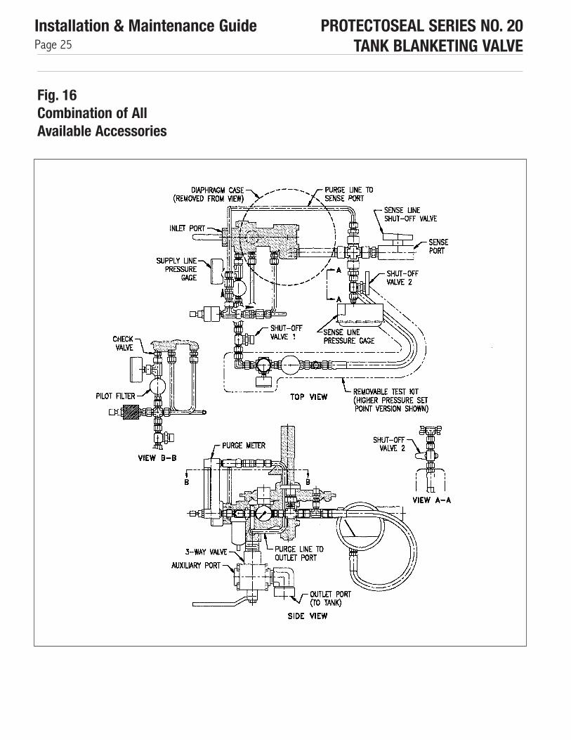
Fig. 16Combination of all Available Accessories

PROTECTOSEAL SERIES NO. 20TANK BLANKETING VALVE
Installation & Maintenance GuidePage 23
Fig. 14Higher Pressure Set PointField Test Kit
Fig. 14Higher Pressure Set Point (2.1 to 69.2 inches W.C.) Field Test KitWith Outlet Line 3-Way Valve & Sense Line Shut-off Valve
PROTECTOSEAL SERIES NO. 20TANK BLANKETING VALVE
Installation & Maintenance GuidePage 24
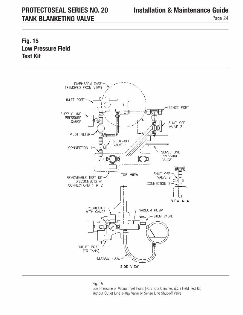
Fig. 15Low Pressure Field Test Kit
Fig. 15Low Pressure or Vacuum Set Point (-0.5 to 2.0 inches W.C.) Field Test KitWithout Outlet Line 3-Way Valve or Sense Line Shut-off Valve
PROTECTOSEAL SERIES NO. 20TANK BLANKETING VALVE
Installation & Maintenance GuidePage 25
Fig. 16Combination of AllAvailable Accessories

PROTECTOSEAL SERIES NO. 20TANK BLANKETING VALVE
Installation & Maintenance GuidePage 26
Troubleshooting Possible problems which could be encountered with a blanketing valve are listed below.Possible sources of the problems along with suggestions for investigating the problems arealso included. Refer to the maintenance instructions for directions on disassembly andreassembly of the blanketing valve and accessories. Refer to Figure 2 through 8 as neces-sary. NOTE: ** Refers to optional equipment which may not be included with your unit
WARNING: Always depressurize the blanketing valve before disassembling.
■ PROBLEM 1 : The blanketing valve does not open at all.
1.1. The blanketing gas supply is empty or shut down or the shut-off valve in the supply line is closed.✔ Inspect the blanketing gas supply source and supply line.
1.2. The shut-off valve in the outlet line is closed.✔ Open the shut-off valve.
1.3 The sense line shut-off valve is closed or the sense line is blocked.✔ Inspect the sense line.
1.4. The set point is too low.✔ CONSULT THE FACTORY FOR ASSISTANCE.
1.5 The diaphragm assembly or the poppet is stuck. Take off the #10 upper case assembly and inspect.✔ Is the #9 diaphragm assembly intact?✔ Was the #6 set spring jammed when you took off the case?✔ Does the #31 poppet move down and spring back up when you press down on
the stem protruding into the lower case? If not, disassemble the pilot valve and check the O-rings, the pin and the spring pin.
1.6. The piston is jammed shut. Remove the pilot body and inspect the main body.✔ Does the #40 piston assembly move freely through the bore.✔ Check for debris in the bore.✔ Inspect the #46 and #47 O-rings.✔ Was the #39 piston spring jammed when you removed the pilot body?✔ Check for marks or raised surfaces on the piston or in the bore. If found, the
main valve and/or piston may require replacement.
■ PROBLEM 2: The blanketing valve flows full open without resealing.
2.1. There is a leak in the sense line or in the tank.✔ Isolate the blanketing valve from the tank, pressurize the tank, and check to see
if it holds pressure.2. There is a leak from the sense chamber.
✔ Leak test the diaphragm case around the perimeter and around the bolts.✔ Leak test around the #15 gasket between the lower case and the pilot body.✔ Check for a hole in the sense diaphragm.✔ Check the #24 gasket in the diaphragm assembly.
2.3. There is a leak in the external filter line.✔ Leak test all fittings.
2.4 The set point is too high. If the set point of the blanketing valve is above that of thepressure relief devices, then neither the blanketing valve or the pressure relief deviceswill close.✔ Compare the specified set points for the blanketing valve and the pressure relief
devices. The blanketing valve set point should be at least 2.0 inches W.C. belowthat of the pressure relief devices.
PROTECTOSEAL SERIES NO. 20TANK BLANKETING VALVE
Installation & Maintenance GuidePage 27
2.5. The piston is stuck open.✔ See #6 in preceding problem.✔ Check for debris at the piston seat (where the #47 O-rings seats).
2.6 The diaphragm assembly or the poppet is stuck.✔ See 1.5.
2.7. An O-ring has been blown out or damaged.✔ Disassemble and inspect.
2.8. The blanketing valve was not reassembled properly after maintenance.✔ Check to see if an O-ring is missing or if the wrong size O-ring was used for the#46 O-ring. Use Table 7 on page 13 to check O-ring sizes.✔ Take apart the pilot valve and check to see that the #32 poppet spring and the33 spring pin are in place.✔ ** Verify that the check valve installed in the proper direction. See the sectionregarding “Integral Purge Accessories”.✔ ** Verify that the shut-off valves for the field test kit are closed See the sectionregarding “Field Test Accessories”.
■ PROBLEM 3: The blanketing valve leaks continuously.3.1. Debris is holding the poppet or piston open.
✔ Take the unit apart, check for debris, clean and reassemble.3.2. An O-ring has been blown out or damaged.
✔ Disassemble and inspect.3.3. The piston is not properly reseated.
✔ Check for debris at the piston seat (where the #47 O-ring seats).✔ See 1.6
3.4. There is a leak in the external filter line.✔ Leak test all fittings.
3.5 There is a leak from the sense chamber.✔ See 2.2
3.6. The diaphragm assembly is stuck or prevented from moving all the way back up.✔ See 1.5
■ PROBLEM 4: The blanketing valve opens above or below the set point.4.1. There is a leak in the sense line.
✔ Leak test connections in the sense line.4.2. There is a leak from the sense chamber.
✔ See 2.2.4.3 The set point is incorrect.
✔ CONSULT THE FACTORY FOR ASSISTANCE.
■ PROBLEM 5: The pressure vent or other pressure relief device opens before the blanketing valve closes.5.1. The set point of the two devices are too close to each other
✔ See 2.4.5.2. The blanketing valve is opening above its set specified set point.
✔ CONSULT THE FACTORY FOR ASSISTANCE.
PROTECTOSEAL SERIES NO. 20TANK BLANKETING VALVE
Installation & Maintenance GuidePage 28
5.3. The pressure relief device is opening below its specified set point.✔ Check the opening pressure of the pressure relief device.
5.4. The blanketing valve is closing too far above its set point. This would indicate that the pilot valve is not functioning properly.✔ Check that the #35 lower plug assembly is screwed in all the way with the mark onthe nut lining up with the mark on the pilot body.✔ Check for debris in the pilot valve.✔ Inspect the O-rings in the pilot valve.✔ Possibly the pilot valve was not reassembled properly after maintenance.
5.5. The blanketing valve flow capacity is too high for the system.✔ Refer to the “User Guide” for assistance in determining flow capacity sizing.
■ PROBLEM 6: The vacuum vent or other vacuum relief device opens.6.1. The blanketing valve set point is below (more negative than) the vacuum vent set
point.✔ Check the labels of the blanketing valve and the vacuum relief device to identify theset points. The set point of one of the units may have to be changed.
6.2 The blanketing valve is opening below its set point.✔ See 1.4.
6.3. The vacuum vent is opening above its set point.✔ Check the opening pressure of the vacuum relief device.
6.4. The blanketing valve flow capacity is not high enough for the system.✔ Refer to the “User Guide” for assistance in determining flow capacity sizing.
■ PROBLEM 7: The blanketing valve cycles, repeatedly opening and closing.7.1. The blanketing valve flow capacity is too high for the system.
✔ Refer to the User’s Guide for assistance in determining flow capacity sizing.7.2 **The check valve in the line between the outlet and the purge meter is not sealing.
✔ Refer to the section on “Integral Purge Accessories” on page 16 for procedureson investigating the operation of the check valve. Replace the check valve if it is founddefective.
NOTE: ** Refers to optional equipment which may not be included with your unit.

V20/2A/3 10/2019 The Protectoseal Company
®PROTECTOSEALSafety Without Compromise
The Protectoseal Company225 W. Foster AvenueBensenville, IL 60106
Phone: 630-595-0800Fax: 630-595-8059
www.protectoseal.com