Embed Size (px)
Citation preview

1
• Unique 3 magnet latching switch mechanism
• No springs in switch mechanism
• Weatherproof
• Flameproof
• Direct mount
• Chamber mount
• Displacer controls
OperationThe float carries a stainless steel sheathed permanent magnet which rises and falls in the glandless pressure tube with changing liquid level. A switch mechanism is mounted inside the enclosure adjacent to the pressure tube. Switching is achieved with the unique Mobrey ‘three-magnet’ system, giving snap-action ‘latch-on’ switching.
Vertical movement of the float magnet in the pressure tube simultaneously actuates the secondary and tertiary magnets in the switch mechanism to operate the contacts. This ‘three-magnet’ system enables the float magnet to pass on and actuate switch mechanisms at other levels. Switch mechanisms already actuated cannot re-set until the return of the primary magnet actuates the magnet system once again.
ATEX
MobreyVertical magnetic level switches
Technical specification sheet
IP107
November 2007 Level
Contents Page
Introduction 3Switch Mechanisms 41. Direct mount displacer controls 5-72. Direct mount float switches 8-93. Chamber mounted controls 3.1 Carbon steel chambers 10-11 3.2 316L stainless steel chambers 12-134. Dimensional and operating level data 145. Technical data and options 156. Applications and users 16
Switch magnet
Float magnet
Secondary magnet
UL LISTED

2
Whether you require a switch for critical area applications or just general purpose control, the extensive range of Mobrey chambers ensures that we will always have a solution to your particular problem.
A choice of carbon steel chambers is available, or for more vigorous applications we supply a series of 316 stainless steel chambers. A variety of tank and process connections is available to make installation simple and economic. This gives you the choice to meet your application in keeping with your budget.
Introduction
Mobrey vertical magnetic level switches for industrial and process control use have been available for over 20 years and have been steadily gaining a reputation for quality and reliability.
Based on the industry standard boiler water level controls these controls employ the same three magnet switch mechanism for snap-action latching switching.
The design of this unique switch mechanism overcomes all the inherent problems of mercury tubes and micro switches. Even under severe vibration conditions there are no springs to cause contact bounce, hover, or even failure. The snap action magnets give positive stable latching time
after time after time.
There are two switching functions available :
2 x SPST (SPCO) switching or DPDT (DPCO) switching, and each comes in four variants :-• General purpose use with silver cadmium oxide contacts for long life.
• Low power circuit with gold plated contacts for use in low current/voltage applications such as I.S. circuits.
• High power circuits giving up to 10A switching
capability.• Hermetically sealed for the ultimate in reliability - sealed for life.
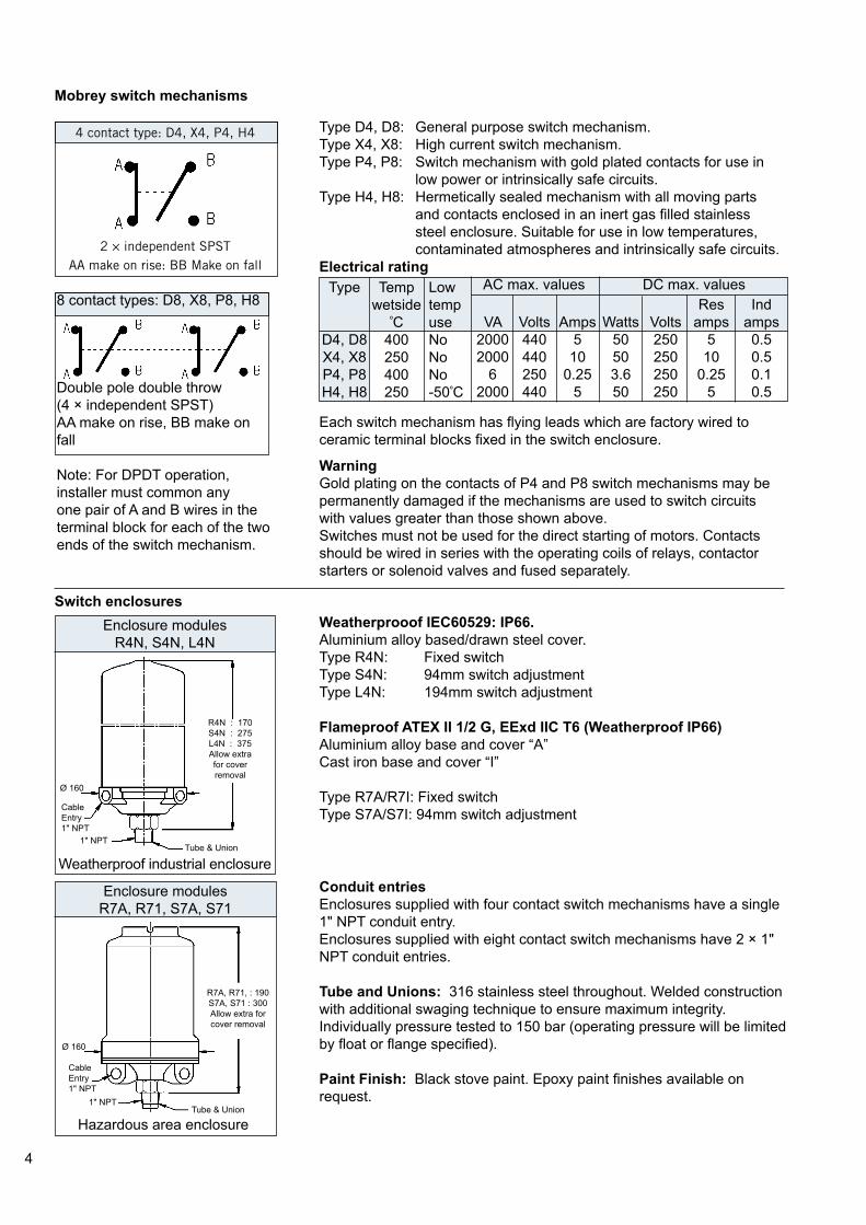
When controls are required to operate in extreme conditions, the unique Mobrey hermetically sealed switch provides dependable life long operation that you can rely on. With all its moving parts and contacts completely enclosed, this genuine hermetically sealed switch is suitable for use in corrosive atmospheres and low temperature environments.
3
Features• Relevant chambers are supplied CE marked and fully compliant with the Pressure Equipment Directive (97/23/EC)• Unique switching mechanism - totally reliable• No springs in switch mechanism - positive snap action switching
• Vibration resistant - eleminates spurious trips• Multi-switching models - cost effective control• Genuine hermetically sealed switch option - totally safe and secure• Extensive range of chambers - suitable for most applications
• Designed to ASME B31.3• Weld procedures approved to BSEN 288-3 and ASME IX• Welders approved to BSEN 287-1• Material certification to EN 10204, 3.1.B• Materials to ASTM and B.S. Standards
ApprovalsMobrey vertical controls are certified ATEX II 1/2 G,EExd IIC T6 (-50° C <Ta<+60° C) in accordance with EN50018.
Flameproof models are available constructed in either aluminium alloy to keep weight to a minimum or cast iron for extended usage in arduous environments.
CSA and UL approved models to special order
Intrinsically Safe UseFor use in intrinsically safe circuits, gold plated switch contacts are recommended (see page 4). Users are reminded that it is their responsibility to obtain the necessary system approval and licences for such circuits.
BS EN ISO 9001 : 2000Mobrey Ltd has been assessed and approved by Lloyds Register Quality Assurance against BS EN 9001 : 2000 for the design, development, assembly and re-calibration of precision instruments and systems for the measurement and indication of electrical signals, gas and liquid density, viscosity, pressure, level, flow and water/steam systems.
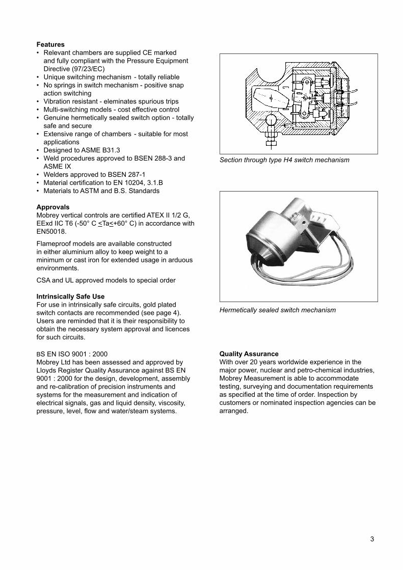
Section through type H4 switch mechanism
Hermetically sealed switch mechanism
Quality AssuranceWith over 20 years worldwide experience in the major power, nuclear and petro-chemical industries, Mobrey Measurement is able to accommodate testing, surveying and documentation requirements as specified at the time of order. Inspection by customers or nominated inspection agencies can be arranged.
4
Enclosure modulesR7A, R71, S7A, S71
Mobrey switch mechanisms
Switch enclosures
4 contact type: D4, X4, P4, H4
2 × independent SPSTAA make on rise: BB Make on fall
8 contact types: D8, X8, P8, H8
Double pole double throw(4 × independent SPST)AA make on rise, BB make on fall
Note: For DPDT operation, installer must common any one pair of A and B wires in the terminal block for each of the two ends of the switch mechanism.
Enclosure modulesR4N, S4N, L4N
Weatherproof industrial enclosure
Type D4, D8: General purpose switch mechanism.Type X4, X8: High current switch mechanism.Type P4, P8: Switch mechanism with gold plated contacts for use in low power or intrinsically safe circuits.Type H4, H8: Hermetically sealed mechanism with all moving parts and contacts enclosed in an inert gas filled stainless steel enclosure. Suitable for use in low temperatures, contaminated atmospheres and intrinsically safe circuits.Electrical rating
Each switch mechanism has flying leads which are factory wired to ceramic terminal blocks fixed in the switch enclosure.
WarningGold plating on the contacts of P4 and P8 switch mechanisms may be permanently damaged if the mechanisms are used to switch circuits with values greater than those shown above.
Switches must not be used for the direct starting of motors. Contacts should be wired in series with the operating coils of relays, contactor starters or solenoid valves and fused separately.
AC max. valuesTemp
wetsideºC
400250400250
Type
D4, D8X4, X8P4, P8H4, H8
Low
temp
use
No
No
No
-50ºC
VA
2000
2000
6
2000
Volts
440440250440
Amps
510
0.255
Watts
50503.6
50
Volts
250250250250
Res
amps
510
0.255
Indamps
0.50.50.1
0.5
Weatherprooof IEC60529: IP66.Aluminium alloy based/drawn steel cover.Type R4N: Fixed switchType S4N: 94mm switch adjustmentType L4N: 194mm switch adjustment
Flameproof ATEX II 1/2 G, EExd IIC T6 (Weatherproof IP66)Aluminium alloy base and cover “A”Cast iron base and cover “I”
Type R7A/R7I: Fixed switchType S7A/S7I: 94mm switch adjustment
Conduit entriesEnclosures supplied with four contact switch mechanisms have a single 1" NPT conduit entry.Enclosures supplied with eight contact switch mechanisms have 2 × 1"
NPT conduit entries.
Tube and Unions: 316 stainless steel throughout. Welded construction with additional swaging technique to ensure maximum integrity. Individually pressure tested to 150 bar (operating pressure will be limited by float or flange specified).
Paint Finish: Black stove paint. Epoxy paint finishes available on request.
Hazardous area enclosure
R4N : 170S4N : 275L4N : 375Allow extra
for cover
removal
Tube & Union
Cable
Entry1" NPT
1" NPT
Ø 160
R7A, R71, : 190S7A, S71 : 300Allow extra for
cover removal
Tube & Union
Cable
Entry1" NPT
1" NPT
Ø 160
DC max. values

5
1.0 Direct mount displacer controls
Mobrey displacer operated controls are ideal for sump application and other top mounting duties such as low level alarm in deep tanks. Their principle of operation also makes them suitable, in a modified form, for very high pressure or low S.G. applications.
The four most popular displacer arrangements are shown in this schematic diagram, which covers most of the likely applications. However, should you have a different requirement, we would be pleased to quote a model for your particular application.
Principle of operation
The displacer element, made of 316 stainless steel, is suspended on a stainless steel cable from a spring. The element is always heavier than its equivalent volume of the liquid in which it is to operate, and so will extend the tension spring at all times. In free air, the spring will be extended to a known length, controlled by a mechanical stop to prevent overstressing. Fixed to the spring is the float rod and magnet assembly, free to move up and down as the spring extends or contracts, and outside the pressure tube in the usual manner is the switch
mechanism.
As liquid rises to cover the displacer element, a bouyancy force is created equal to the weight of the liquid displaced. This force in effect is seen by the spring as a reduction in weight, causing the spring to contract, hence moving the magnet upwards inside the pressure tube and actuating the switch mechanism. On a falling liquid level, the displacer element is uncovered and the spring sees an increasing effective weight, causing the spring to extend and move the magnet to re-set the switch mechanism (Fig i and v).
This simple principle can be refined to operate a single switch over a very wide differential by providing the buoyancy force from two elements instead of just one (Fig ii).
Two switch models are available for either two alarm duty with two narrow differentials (Fig iii) or for pump control/alarm duty with appropriate differentials (Fig iv).
Displacer control
In all cases, because the elements are suspended on a cable, switching or control levels can be several metres
below the mounting flange, and are fully field adjustable by re-setting the elements on the cable.
Fig i
Fig ii
Fig iii
Fig iv
One switch alarm
differential
One switch pump
control
Two switch
two alarm
Two switch
alarm andpump control
Differential
Differential
Differential
No. 1
Differential
No. 2
Pump
differential
Alarm
or pump
differential
Fig v

6
▼
/
Max. wetsidetemperature
300ºC
300ºC
250ºC250ºC
300ºC
300ºC
250ºC250ºC
Function
One switchnarrow diff.One switchwide diff.
Two switch
2 wide diff.Two switch
2 normal diff.Code Switch enclosure
S4N
S7A
S7I
Code Displacer function and specification
Code Number of switch mechanisms1 Specify 1 for single switch models 11D, 12D2 Specify 2 for two switch models 13D, 18D
Displacer controls: ordering information
Code Material of mounting flangeC Carbon steel. ASTM A105 (For use +300ºC to -10ºC)S 316L stainless steel. ASTM A182: F316L (For use +300ºC to -50ºC)
Code Displacer operated alarm and pump control switchesD Direct mount: Displacer controls
Elements316 S.S.
316 S.S.
316 S.S.
316 S.S.
Trim
316
StainlessSteel
Spring
Nimonic
90
4 Contact 8 ContactS.G. Range
0.6 - 1.2
0.5 - 1.2
0.6 - 1.2
0.6 - 1.2
0.75 - 1.2
0.75 - 1.2
0.8 - 1.2
0.8 - 1.2
Operatingtemp. range
-50ºC to +300ºC
-50ºC to +300ºC
-50ºC to +300ºC
-50ºC to +300ºC
Max. pres.20ºC
102
bar
DutyWeather proof
IP66
Flameproof
ATEX II 1/2 GEExdIICT6
Base
Aluminium
alloy*Aluminium
alloy*Cast
iron
Cover
Drawn
steel
Aluminium
alloyCast
iron
Material ofwetted parts
316
stainless
steel
Switchadjustment
Adjustswitching point
by movingdisplacerelements
on cable
Max. no. of switch mechanisms
2
Material of
* Base material will be cast iron whenever 8 contact switches are specified
Code Type of switch mechanismSwitch mechanism
duty4 Contact: 2 × SPSTGeneral purpose
Low power circuits
High power circuits
Hermetically sealed8 Contact: DPDTGeneral purpose
Low power circuits
High power circuits
Hermetically sealed
Volts
440250440440
440250440440
Amps
50.2510
5
50.2510
5
VA
2000
6
2000
2000
2000
6
2000
2000
Volts
250250250250
250250250250
Res. I
50.2510
5
50.2510
5
Ind. I
0.50.1
0.50.5
0.50.1
0.50.5
Watts
503.6
5050
503.6
5050
D.C. max. valuesA.C. max. values
D C 13D S7A 2 D4 / 60 Typical ordering information
Note: Customers must state operating pressure, temperature and specific gravity, together with function of each switch mechanism when ordering.
Due to component tolerances, dimensions DB, E and S given on page 7 are approximate and may vary on each control by up to 10mm. Setting the control to operate at the required level can be achieved on site by adjusting the element up or down on the cable as necessary.
Material of
11D
12D
13D
18D
D4P4X4H4
D8P8X8H8
Code Mounting arrangement0 1" N.P.T. Thread: 316 stainless steel standard These are our60 3" Class 150 R.F. ASME B16.5 stocked flanges.61 3" Class 300 R.F. ASME B16.5 Other flange62 3" Class 600 R.F. ASME B16.5 sizes and ratings65 4" Class 150 R.F. ASME B16.5 are available66 4" Class 300 R.F. ASME B16.5 on67 4" Class 600 R.F. ASME B16.5 request.
▼ ▼ ▼ ▼ ▼ ▼ ▼

7
4 Contact: D4 P4 X4 H4 8 Contact: D8 P8 X8 H8 Weatherproof: S4N Flameproof: S7A S7I
Displacer types and dimensional detailsSingle switch wide differential: 12D
The two displacer elements are positioned at any point on the cable to correspond to the switching levels required. When the liquid level drops to the lower displacer the switch is actuated and starts (or stops) a pump; when the liquid rises to the upper displacer the switch is again actuated to stop (or start) the pump.
12D St. Steel: A = 216 ∅ = 60.3
S min = Adjustable distance to upper switching level.
E min = DifferentialDB = Minimum dead band
Two switch 2 narrow differentials: 18D
The displacers are positioned to form two elements of similar lengths, such that two alarm points may be given. This arrangement is typical of sump application.
18D St. Steel: A = 216 ∅ = 60.3
Two switch 2 wide differentials: 13D
A pump is controlled between the middle and the lower pump displacers positioned on the cable at the required levels. Should the level rise to the upper displacer this actuates the upper alarm switch which remains
actuated until the level drops to the middle displacer.Alternatively, the upper switch could control a second pump.
Switch mechanisms Switch enclosures
Single switch narrow differential: 11D
Specify for alarm duty.Switching level can be changed by simply moving the displacer up or down the cable.
11D St. Steel : A = 216 ∅ = 60.3
SwitchtypesS.G.S minE min
D4
0.5415165
P4
0.8430110
X4
1.0
43095
H4
1.2
42580
D8
0.75390205
P8
0.8390200
X8
1.0
400165
H8
1.2
400140
1.2
34090
SwitchtypesS.G.S min
E
D4
0.6
31590
P4
0.7533570
X4
1.0
36560
H4
1.2
38055
0.75275135
1.0
320
105
D8 P8 X8 H8
SwitchtypesS.G.S minE min
Dead band
D4
0.6
39090
200
P4
0.838570
230
X4
1.0
37560
255
H4
1.2
36555310
0.8355135165
1.0
350105215
D8 P8 X8 H8
1.2
34590
250
SwitchtypesS.G.S minE min
Dead band
D4
0.6
390135220
P4
0.8385110
255
X4
1.0
37595
285
H4
1.2
36580310
0.8355200
165
1.0
350145215
1.2
345140250
D8 P8 X8 H8
2 × independent SPSTAA make on rise:BB Make on fall
Double pole double throw(4 × independent SPST)
AA make on rise, BB make on fall
S7A, S71 : 300Allow extra
for cover
removal
Tube & Union
Cable
Entry1" NPT
1" NPT
Ø 180
S4N : 275Allow extra
for cover
removal
Tube & Union
Cable
Entry1" NPT
1" NPT
Ø 160
∅
S
A E
∅
S
A
EA
∅
S
EA
A E
DB
∅
S
E
A
B
A
E
DB
13D St. Steel: A = 152 B = 304 ∅ = 60.3

8
C Carbon steel ASTM A105 (for use + 400oC to -10oC)S 316L stainless steel ASTM A182: F316L (for use + 400oC to -101oC)
2.0 Direct Mounting Float Switches: Ordering Information
Code Float operated alarm and pump control switchesD Direct mount: Float switches
Code Material of mounting flange
Float
diameter67
908888
Matching mounting flanges3" NB and larger
4" NB minimum
11F
12F
13F
14F
20°C34.5102.1
51.119.6
250°C22.566.3
33.2
12.7
400°C20.0
59.229.611.3
Matching enclosures
All models
R4NS4NL4NR7A
S7AR7I
S7I
DutyWeatherproof
IP66
Flameproof
ATEX II 1/2 GEExdIICT6
Material of base
Aluminium
alloy*
Aluminium
alloy*Cast
iron
Material ofwetted parts
316
stainless
steel
Switchadjustment
None
94mm194mmNone
94mmNone
94mm
Material of cover
Drawn
steel
Aluminium
alloyCast
iron
Switch mechanism duty
4 contact: 2 x SPSTGeneral purpose
Low power circuits
High power circuits
Hermetically sealed8 contact: DPDT
General purpose
Low power circuits
High power circuits
Hermetically sealed
Max. wetside temp.
400oC
400oC
250oC
250oC
400oC
400oC
250oC
250oC
Amps
50.2510
5
50.2510
5
VA
2000
6
2000
2000
2000
6
2000
2000
AC max values
Volts
250250250250
250250250250
Res. I
50.2510
5
50.2510
5
Ind. I
0.50.1
0.50.5
0.50.1
0.50.5
DC max values
Watts
503.6
5050
503.6
5050
Code Mounting arrangement0 1" NPT thread: 316 stainless steel standard60 3" Class 150RF ASME B16.561 3" Class 300RF ASME B16.562 3" Class 600RF ASME B16.565 4" Class 150RF ASME B16.566 4" Class 300RF ASME B16.567 4" Class 600RF ASME B16.5
These are our
stocked flanges. Other flange sizes and ratings are available on
request
D C 12F L4N 4 D4 / 67 Typical ordering information
Minimum S.G.0.800.750.650.54
Pressure rating (bar)
4 Contact1
46
1
41
4
8 Contact1
2
3
1
2
1
2
*Base material will be cast iron whenever 8 contact switches specified.
Note : Instrument pressure rating is the lower of either the float or mounting flange
Code Floats
Code Switch Enclosure
Code Type of switch mechanism
Max. no. of switches
Code Number of switch mechanisms1-6 As required: see max. number allowable in switch enclosure data above
D4P4X4H4
D8P8X8H8
Volts
440250440440
440250 440 440
9
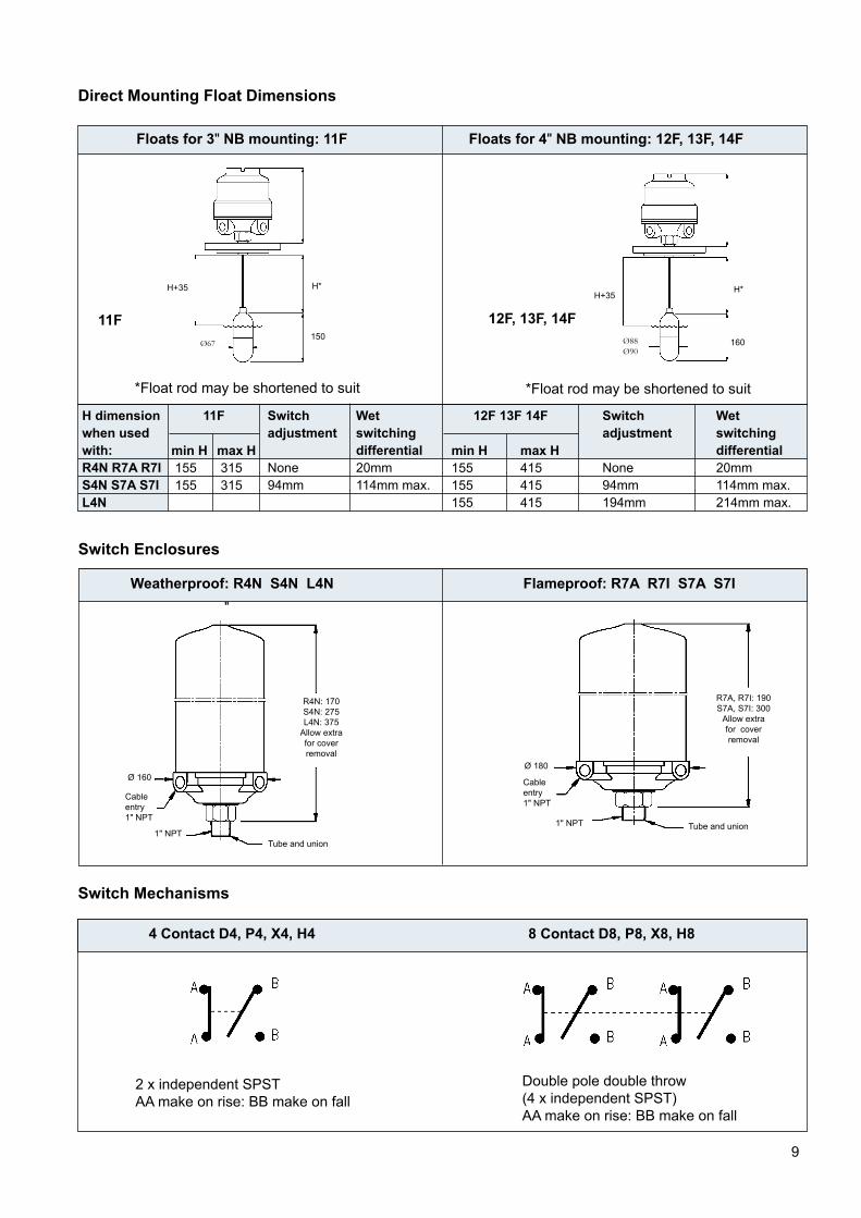
Direct Mounting Float Dimensions
Switch Enclosures
Switch Mechanisms
Floats for 3" NB mounting: 11F Floats for 4" NB mounting: 12F, 13F, 14F
*Float rod may be shortened to suit *Float rod may be shortened to suit
H dimension when used with:R4N R7A R7IS4N S7A S7IL4N
11F
min H 155 155
max H 315 315
Switchadjustment
None
94mm
Wet switching differential20mm
114mm max.
12F 13F 14F
min H155155155
max H415415415
Switchadjustment
None
94mm194mm
Wet switching differential20mm
114mm max.214mm max.
Weatherproof: R4N S4N L4N Flameproof: R7A R7I S7A S7I
4 Contact D4, P4, X4, H4
2 x independent SPSTAA make on rise: BB make on fall
Double pole double throw(4 x independent SPST)AA make on rise: BB make on fall
8 Contact D8, P8, X8, H8
12F, 13F, 14F
R4N: 170S4N: 275L4N: 375
Allow extra
for cover
removal
Cable
entry 1" NPT
Tube and union1" NPT
Ø 160
11F
R7A, R7I: 190S7A, S7I: 300
Allow extra
for cover
removal
Cable
entry 1" NPT
Tube and union1" NPT
Ø 180
H+35 H*
150Ø67
H+35H*
160Ø88Ø90
"

10
3.0 Carbon Steel Chamber Mounted Controls: Ordering InformationCode Chamber mounted controlsB Bottle Style: Float sealed inside chamber during manufactureX Flanged Style: Float may be removed from chamber for routine maintenance
Flanged Style chambers (X)Pressure rating (bar)
Refer to page15 for process connection
ratings
Note: single switch only
Chamber
body size
3" N.B.
4" N.B.Switch Enclosure
Duty
Weatherproof
IP66
Flameproof
ATEX II 1/2 GEExdIICT6
Base Cover
Material of Material ofwetted parts
316
stainless
steel
Switchadjustment
Max. no. of switches4 Contact 8 Contact
* Base material will be cast iron whenever 8 contact switches are specified
/
Chamber
3" & 4" N.B.
4" N.B. only
These are our
stocked sizes
Other flangesizes and ratingsare available
on request
Instrument
pressure
rating is the lower
of either the floator process flange
X C 14F S7A 2 D4 / 2 10 Typical ordering information
Note: State process connection centres when ordering. See page 14 for standard dimensions. Instrument pressure rating is the lower of either the float or the process flange.
Code Material of contruction of chamberC Carbon steel: See page 15
Float & trim
material
316
stainless
steel
MinimumS.G
0.800.750.650.540.40
20ºC
34.5102.1
51.119.6
102.1
250ºC22.566.3
33.2
12.7
66.3
400ºC20.0
59.229.611.3
59.2
Code FloatsBottle Style chambers (B)
Pressure rating (bar)20ºC
30.1
88.844.617.1
88.8
250ºC22.566.3
33.2
12.7
66.3
400ºC20.0
59.229.611.3
59.2Code
R4NS4NR7A
S7AR71
S71
Max. wetsidetemperature Volts Amps VA Volts Res. I Ind. I Watts
Code Type of switch mechanismSwitch mechanism
duty4 Contact: 2 × SPST
General purpose
Low power circuits
High power circuits
Hermetically sealed
400ºC400ºC250ºC250ºC
400ºC400ºC250ºC250ºC
Code Process connection configuration1 Side/bottom2 Side/side with 1" NPT drain
A.C. max. values D.C. max. values
▼ ▼ ▼ ▼ ▼ ▼ ▼ ▼ ▼
Code Process connection size & rating01 1" N.P.T.: 316 s/s standard11 1" Class 150 R.F. ASME B16.512 1" Class 300 R.F. ASME B16.513 1" Class 600 R.F. ASME B16.515 DN25 PN16 EN 1092-116 DN25 PN25 EN 1092-117 DN25 PN40 EN 1092-118 DN25 PN64 EN 1092-119 DN25 PN100 EN 1092-121 1½" Class 150 R.F. ASME B16.5 22 1½" Class 300 R.F. ASME B16.523 1½" Class 600 R.F. ASME B16.525 DN40 PN16 EN 1092-131 2" Class 150 R.F. ASME B16.532 2" Class 300 R.F. ASME B16.533 2" Class 600 R.F. ASME B16.535 DN50 PN16 EN 1092-136 DN50 PN25 EN 1092-137 DN50 PN40 EN 1092-1
440250440440
440250440440
50.2510
5
50.2510
5
2000
6
2000
2000
2000
6
2000
2000
250250250250
250250250250
50.2510
5
50.2510
5
0.50.1
0.50.5
0.50.1
0.50.5
503.6
5050
503.6
5050
Aluminium
alloy*Aluminium
alloy*Cast
iron
Drawn
steel
Aluminium
alloyCast
iron
None
94mmNone
94mmNone
94mm
1
41
41
4
1
2
1
2
1
2
11F
12F
13F
14F17D
Code Number of switch mechanisms1 - 4 As required: see max. number allowable in switch enclosure and float data above
D4P4X4H4
D8P8X8H8
8 Contact: DPDTGeneral purpose
Low power circuits
High power circuits
Hermetically sealed

11
Chamber Type and Material of Construction
Carbon steel: Bottle construction
BC
Float is sealed inside chamber during manufacture
Carbon steel: Flanged constructionXC
Float may be removed from chamber for routine maintenance, cleaning or inspection
Switch EnclosuresWeatherproof: R4N S4N Flameproof: R7A S7A R71 S71
Switch Mechanisms4 contact: D4 P4 X4 H4
2 × independent SPSTAA make on rise: BB make on fall
8 contact: D8 P8 X8 H8
Double pole double throw (4 × independent SPST)AA make on rise: BB make on fall
Process Connection Configuration
Side and Bottom - 1 Side and Side with Drain - 2
Chamber dimensions, operating levels and technical data are given on page 14
R7A, R7I: 190S7A, S7I: 300
Allow extra
for cover
removal
Cable
entry 1" NPT
Tube and union1" NPT
Ø 180
R4N: 170S4N: 275
Allow extra
for cover
removal
Cable
entry 1" NPT
Tube and union1" NPT
Ø 160

12
Code Switch Enclosure
R4NS4NR7A
S7AR7I
S7I
Code Chamber mounted controlsB Bottle Style: Float sealed inside chamber during manufactureX Flanged Style: Float may be removed from chamber for routine maintenance
4.0 316L Stainless Steel Chamber Mounted Controls: Ordering Information
Float and trimmaterial
316
stainless
steel
MinimumS.G
0.750.650.540.40
20ºC
102.1
51.119.6102.1
250ºC66.3
33.2
12.7
66.3
400ºC59.229.611.3
59.2
Chamber
body size
4" N.B.
Material of Max. no. of switches
* Base material will be cast iron whenever 8 contact switches are specified
A.C. max. values
Volts
440250440440
440250440440
Amps
50.2510
5
50.2510
5
VA
2000
6
2000
2000
2000
6
2000
2000
Volts
250250250250
250250250250
Res. I
50.2510
5
50.2510
5
Ind. I
0.50.1
0.50.5
0.50.1
0.50.5
Watts
503.6
5050
503.6
5050
D.C. max. values
/
B S 17D 4N 1 X8 / 2 33 Typical ordering informationNote: State process connection centres when ordering. See page 14 for standard dimensions. Instrument pressure rating is the lower of either the float or the process flange.
Code Floats
12F
13F
14F17D
Flanged Style chambers (X)Pressure rating (bar)
20ºC
88.844.617.1
88.8
250ºC66.3
33.2
12.7
66.3
400ºC59.229.611.3
59.2
Bottle Style chambers (B)Pressure rating (bar)
Refer to page15 for process
connection ratings
Note: single switch
only
DutyWeatherproof
IP66
Base
Aluminium
alloy*Aluminium
alloy*Cast
iron
Cover
Drawn
steel
Aluminium
alloyCast
iron
Material ofwetted parts
316
stainless
steel
Switchadjustment
None
94mmNone
94mmNone
94mm
4 Contact1
41
41
4
8 Contact1
2
1
2
1
2
Flameproof
ATEX II 1/2 GEExd II C T6
▼
Code Process connection size & rating01 1" N.P.T. 316 stainless steel standard11 1" Class 150 R.F. ASME B16.512 1" Class 300 R.F. ASME B16.513 1" Class 600 R.F. ASME B16.521 1½" Class 150 R.F. ASME B16.522 1½" Class 300 R.F. ASME B16.523 1½" Class 600 R.F. ASME B16.531 2" Class 150 R.F. ASME B16.532 2" Class 300 R.F. ASME B16.533 2" Class 600 R.F. ASME B16.5
Code Material of contruction of chamberS 316L stainless steel: see page 15
Code Number of switch mechanisms1 - 4 As required: see max. number allowable in switch enclosure and float data above
Code Type of switch mechanism
D4P4X4H4
D8P8X8H8
Max. wetsidetemperature
400ºC400ºC250ºC250ºC
400ºC400ºC250ºC250ºC
Code Process connection configuration1 Side/bottom2 Side/side with 1" NPT drain
▼ ▼ ▼ ▼ ▼ ▼ ▼ ▼
Switch mechanismduty
4 Contact: 2 × SPSTGeneral purpose
Low power circuits
High power circuits
Hermetically sealed8 Contact: DPDT
General purpose
Low power circuits
High power circuits
Hermetically sealed

13
Chamber Type and Material of Construction
Carbon steel: Bottle construction
BS
Float is sealed inside chamber during manufacture
Carbon steel: Flanged constructionXS
Float may be removed from chamber for routine maintenance, cleaning or inspection
Switch EnclosuresWeatherproof: R4N S4N Flameproof: R7A S7A R71 S71
Switch Mechanisms4 contact: D4 P4 X4 H4
2 × independent SPSTAA make on rise: BB make on fall
8 contact: D8 P8 X8 H8
Double pole double throw (4 × independent SPST)AA make on rise: BB make on fall
Process Connection Configuration
Side and Bottom - 1 Side and Side with Drain - 2
Chamber dimensions, operating levels and technical data are given on page 14
R7A, R7I: 190S7A, S7I: 300
Allow extra
for cover
removal
Cable
entry 1" NPT
Tube and union1" NPT
Ø 180
R4N: 170S4N: 275
Allow extra
for cover
removal
Cable
entry 1" NPT
Tube and union1" NPT
Ø 160

14
Dimensional and Operating Level Data
Style 2: Side and Side
Singleswitch
‘R’ head300
-356356356356356356356356356356356356356356356356356
0.465118
Multi-type
‘S’ head385
-441441441441441441441441441441441441441441441441441
0.573
122
50505050505050505050505050505050505050
0.7
91132
Singleswitch
‘R’ head70
70
70
70
70
70
70
70
70
70
70
70
70
70
70
70
70
70
70
0.8100
137
Multi-switch
‘S’ head155155155155155155155155155155155155155155155155155155155
0.9109141
Singleswitch
‘R’ head-
271
271
271
271
271
271
271
271
271
271
271
271
271
271
271
271
271
271
1.0
118147
Multi-switch
‘S’ head-
356356356356356356356356356356356356356356356356356356
1.1
127
152
BC/BS48/160
160
160
160
160
160
160
160
160
160
160
160
160
160
160
160
160
160
160
1.2
136
156
XC/XS225225225225225225225225225225225225225225225225225225225
A B* C D E F
Chamber typeProcess
connections
Notes: C = Highest operating liquid level D (Multi switch) = Lowest operating liquid level D (Single switch) = Reset level D-C = Wet switching differential (max)All dimensions in mm.
NOTE: Dimensions given are for reference only, and must be certified on order.
Switch adjustmentNone
94None
94194
Weatherproof rating
IP66 to IEC60529(NEMA 4)
IP66 to IEC60529(NEMA 4)
B
E
F
G
160
Drain
1" NPTB
E
F
G
160
Drain
1" NPT
CDC
D
B
A
F
G
B
A
F
G
Screwed Flanged
Flameproof
ATEX II 1/2 GEExdIICT6
Weatherproof
*Enclosures for use with 8 contact switch mechanisms have both conduit entries threaded, whilst those for use with 4 contact switch mechanisms have only one conduit entry.
Chamber
typeBC/others
76/9595110
117
123
949696114114115121
126
97112
11812998101
0.6
82127
1" NPT (side/bottom)1" NPT (side/side)1" 1501" 300
1" 600
DN25 PN16DN25 PN25DN25 PN40DN25 PN64DN25 PN1001½" 1501½" 300
1½" 600
DN40 PN162" 1502" 300
2" 600
DN50 PN16DN50 PN25B* Dimension given is for 4" NB chamber (12F, 13F, 14F & 17D Floats). For 3" NB chamber (11F Float) subtract 13mm.
Operating levels: Type 17D float in any chamber.
Operating S.G.Dimension C
Dimension D
Style 1: Side and Bottom
Dimensional data: enclosuresTypeR7A, R7IS7A, S7IR4NS4NL4N
Conduit thread*1" NPT
1" NPT
Height G
190300
170
275375
Duty

15
Mobrey vertical level controls are manufactured to the highest standards of quality with only certified materials: BS EN 10204 : 2004-3.1. Design of Mobrey chambers is in accordance with ASME B31.3. Relevant chambers are supplied CE marked and fully compliant with the Pressure Equipment Directive (97/23/EC).
Weld procedures approved to EN ISO 15614-1 and ASME IX, welders approved to BSEN 287-1. Circumferential and set-on branch welds are full penetration welds, with visual inspection in accordance with ASME B31.3 "normal service"
requirements and our company standard 417.
All pressure retaining assemblies are hydrostatically pressure tested to a minimum of 1.43 × maximum working pressure or to flange standard requirements.
Radiography or other NDT techniques can be accommodated provided that they are specified at time of order entry.
InspectionWhilst Mobrey employ inspectors in house, unconnected with production, customers frequently ask for outside inspection. We are happy to accommodate nominated inspectors if agreed at order entry.
Some specifications require a quality control plan detailing inspection points and hold points. Mobrey will produce these QC plans for customer approval if agreed at order entry.
Technical Data
Pressure Ratings (bar)
Material Carbon steel: A105 Stainless steel: 316L
20ºC
19.651102
16
2540
250ºC12.1
41.783.614.422.536
400ºC6.5
34.569
10.816.927
20ºC
15.841.382.712.3
19.230.6
250ºC10.1
26.6
53.47.9
12.419.8
400ºC6.523
46.16.8
10.7
17.1
Technical specification
Materials of construction Carbon steel chamber Stainless steel chamberChamber tube ASTM A106 grade B ASTM A312 TP316L Top casting ASTM A216 - -Top/bottom caps ASTM A105 ASTM A182 F316L / A403 WP316LTop cover ASTM A105 ASTM A182 F316L Flanges/fittings ASTM A105 ASTM A182 F316Studs ASTM A193-B7 ASTM A320-L7 Nuts ASTM A194-2H ASTM A194 Grade 7+S3
Standard carbon steel chambers +400ºC to -10ºC. Stainless steel chambers below +400°C to -101°C
Options• Low temperature carbon steel • Ratings up to ASME Class 2500 • N.A.C.E. requirements • Process connections to specification • Cr. mo. steels • N.D.T. to your specifications• Duplex UNS31803 • 3.1 Identifiable certification • Vent and drain connections
Pressure tube & union.
Swaged & welded construction
Magnet sheathed in 316 st. steel
‘0’ ring seal to base
Full
penetration
welding
Weld neck flanges used throughout
Float
ASME B16.5 Class 150ASME B16.5 Class 300ASME B16.5 Class 600BS EN 1092-1 PN16BS EN 1092-1 PN25BS EN 1092-1 PN40

16
Mobrey “Fit and Forget” Products Provide The Solution To Your Liquid Level Control Problems
Medium pressuresASME Class 150, 300 600SG 0.4Pages 10-13
High pressures
ASME Class 900, 1500, 2500SG 0.40To order
Direct mounting
ASME Class 150, 300, 600SG 0.4Pages 5-9
The Mobrey range of vertical liquid level controls is designed for operation in a wide variety of applications.
Typical Applications
Separators Water SumpsCompressors ScrubbersKnock-out Pots Fractioning ColumnsCondensors Flash VesselsDe-aerators Process VesselsStorage Tanks Condensate TanksService Tanks DrainpotsHeader Tanks AccumulatorsEffluent Sumps & Tanks Fuel TanksHeat Exchangers Feedwater HeatersLude Oil Tanks Surge Drums
Mobrey level switches are used for the control of liquids by companies all over the world.
Shell BechtelExxon BelliliAmoco Ontario HydroFluos Nissaei-SangyoHyundai Foster WheelerBritish Petroleum SiemensMobil Mannesmann-DemagTexaco CatalyticIngersoll Rand TechniCompair Technipetrol
Honeywell Nuovo PignoneWemco Dresser
You can rely on us
Technical specification sheet
IP107
November 2007Level
Americas:
Emerson Process Management8200 Market BoulevardChanhassen, MN USA 55317T (US) (800) 999-9307T (International) 952) 906-8888F (952) 949-7001
International:
Emerson Process ManagementMobrey Measurement 158 Edinburgh Avenue, Slough, Berks UK SL1 4UET +44 (0)1753 756600 F +44 (0)1753 823589www.mobrey.com
The Emerson logo is a trade mark and service mark of Emerson Electric Co.Mobrey is a registered trademark of Mobrey Ltd.All other marks are the property of their respective ownersWe reserve the right to modify or improve the designs or specifications of product and services at any time without notice.