Embed Size (px)
Citation preview


ZTD Series Smart Displacer Level (Interface) Transmitter
Summary
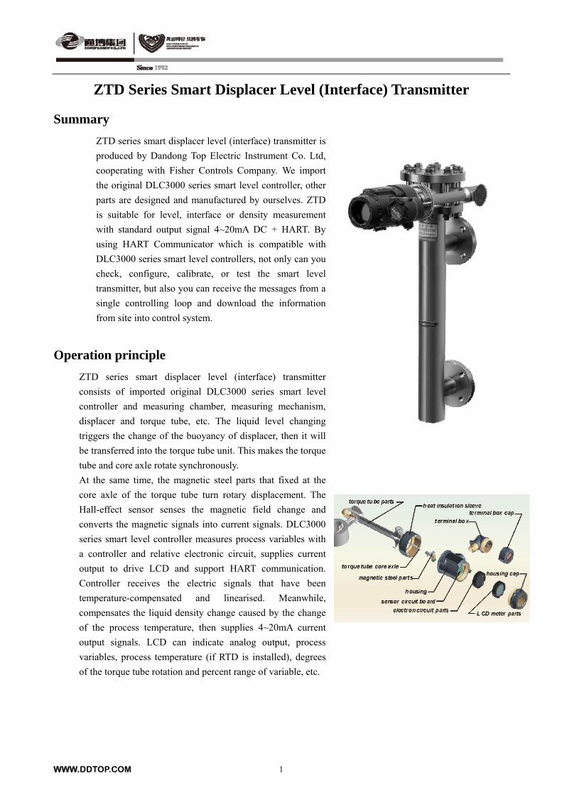
ZTD series smart displacer level (interface) transmitter is
produced by Dandong Top Electric Instrument Co. Ltd,
cooperating with Fisher Controls Company. We import
the original DLC3000 series smart level controller, other
parts are designed and manufactured by ourselves. ZTD
is suitable for level, interface or density measurement
with standard output signal 4~20mA DC + HART. By
using HART Communicator which is compatible with
DLC3000 series smart level controllers, not only can you
check, configure, calibrate, or test the smart level
transmitter, but also you can receive the messages from a
single controlling loop and download the information
from site into control system.
Operation principle
ZTD series smart displacer level (interface) transmitter
consists of imported original DLC3000 series smart level
controller and measuring chamber, measuring mechanism,
displacer and torque tube, etc. The liquid level changing
triggers the change of the buoyancy of displacer, then it will
be transferred into the torque tube unit. This makes the torque
tube and core axle rotate synchronously.
At the same time, the magnetic steel parts that fixed at the
core axle of the torque tube turn rotary displacement. The
Hall-effect sensor senses the magnetic field change and
converts the magnetic signals into current signals. DLC3000
series smart level controller measures process variables with
a controller and relative electronic circuit, supplies current
output to drive LCD and support HART communication.
Controller receives the electric signals that have been
temperature-compensated and linearised. Meanwhile,
compensates the liquid density change caused by the change
of the process temperature, then supplies 4~20mA current
output signals. LCD can indicate analog output, process
variables, process temperature (if RTD is installed), degrees
of the torque tube rotation and percent range of variable, etc.
WWW.DDTOP.COM 1
ZTD series Smart Displacer Level (Interface) Transmitter
Main technical parameter
Power supply: 12~30V DC; the controller has reverse polarity protection.(when HART is
communicating, the voltage of controller ≥17.75V DC)
Output signal: 4~20 mA DC (Positive direction – the increase of level, interface, or density make output
increase; Negative direction – the increase of level, interface, or density make output
decrease.)
Measuring range: 300mm—2500mm (can also over range)
Nominal pressure: ≤42.0Mpa
Nominal diameter: DN40 or as customers’ request
Ambient temperature: –40ºC to +80ºC (when ≤–30ºC, no LCD display)
Operating temperature: –70ºC to +400ºC
Measuring accuracy: 0.5%
Influence from power supply: When the voltage of the power supply varies between min. and max. ,the
output change is within <±0.2%. of the full scale.
LCD display: Output current signal、process variable、process temperature、percentage range、rotation angle
of torque tube.
Medium density difference: ≥0.08g/cm³
Material of torque tube: Standard configuration Inconel 600,or Monel, HasetlloyC-276
Wetted material: 304、316L or as customers’ request
Flange standard: HG/T20592-2009、HG/T20615-2009 or as customers’ request
Power entry: Two NPT 1/2 (female thread) or as customers’ request
Explosion-proof: Explosion isolation ExdⅡCT6, Intrinsically safe ExiaⅡCT6
Protection grade: IP66
Alarm jumper: For the self-diagnosis to the inaccuracy failure of the process variables (for example, the
electronic module failure). Configure the process variables of high and low alarms.
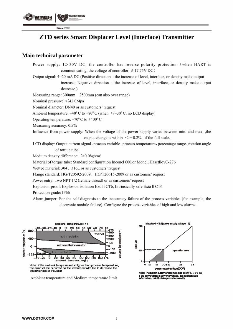
Ambient temperature and Medium temperature limit
WWW.DDTOP.COM 2
WWW.DDTOP.COM 3
ZTD series Smart Displacer Level (Interface) Transmitter
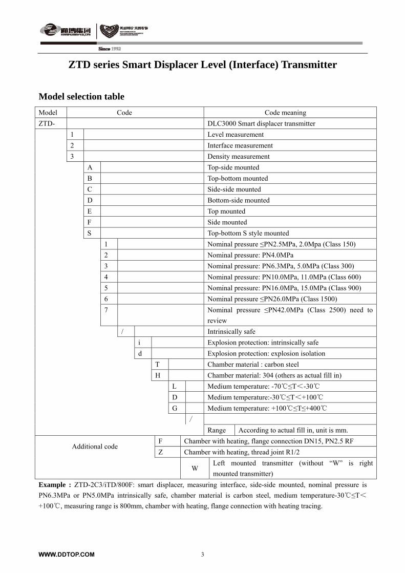
Model selection table
Model Code Code meaning
ZTD- DLC3000 Smart displacer transmitter
1 Level measurement
2 Interface measurement
3 Density measurement
A Top-side mounted
B Top-bottom mounted
C Side-side mounted
D Bottom-side mounted
E Top mounted
F Side mounted
S Top-bottom S style mounted
1 Nominal pressure ≤PN2.5MPa, 2.0Mpa (Class 150)
2 Nominal pressure: PN4.0MPa
3 Nominal pressure: PN6.3MPa, 5.0MPa (Class 300)
4 Nominal pressure: PN10.0MPa, 11.0MPa (Class 600)
5 Nominal pressure: PN16.0MPa, 15.0MPa (Class 900)
6 Nominal pressure ≤PN26.0MPa (Class 1500)
7 Nominal pressure ≤PN42.0MPa (Class 2500) need to
review
/ Intrinsically safe
i Explosion protection: intrinsically safe
d Explosion protection: explosion isolation
T Chamber material : carbon steel
H Chamber material: 304 (others as actual fill in)
L Medium temperature: -70≤T<-30
D Medium temperature:-30≤T<+100
G Medium temperature: +100≤T≤+400
/
Range According to actual fill in, unit is mm.
F Chamber with heating, flange connection DN15, PN2.5 RF Additional code
Z Chamber with heating, thread joint R1/2
W
Left mounted transmitter (without “W” is right
mounted transmitter)
Example : ZTD-2C3/iTD/800F: smart displacer, measuring interface, side-side mounted, nominal pressure is
PN6.3MPa or PN5.0MPa intrinsically safe, chamber material is carbon steel, medium temperature-30≤T<
+100, measuring range is 800mm, chamber with heating, flange connection with heating tracing.
ZTD series Smart Displacer Level (Interface) Transmitter
WWW.DDTOP.COM 4
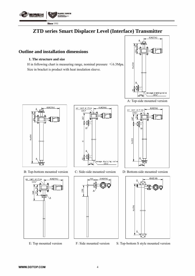
Outline and installation dimensions
1. The structure and size
H in following chart is measuring range, nominal pressure ≤6.3Mpa.
Size in bracket is product with heat insulation sleeve.
A: Top-side mounted version
B: Top-bottom mounted version C: Side-side mounted version D: Bottom-side mounted version
E: Top mounted version F: Side mounted version S: Top-bottom S style mounted version
WWW.DDTOP.COM 5
ZTD series Smart Displacer Level (Interface) Transmitter
2. Mounting orientation of the smart level controller
Mount the controller on the chamber. When the controller is mounted on the right of the displacer
chamber, the transmitter is called right-mounted, so when the level increases, torque tube turns in
clockwise. When the controller is mounted on the left of the displacer chamber, the transmitter is called
left-mounted, so when the level increases, torque tube turns in counter-clockwise.
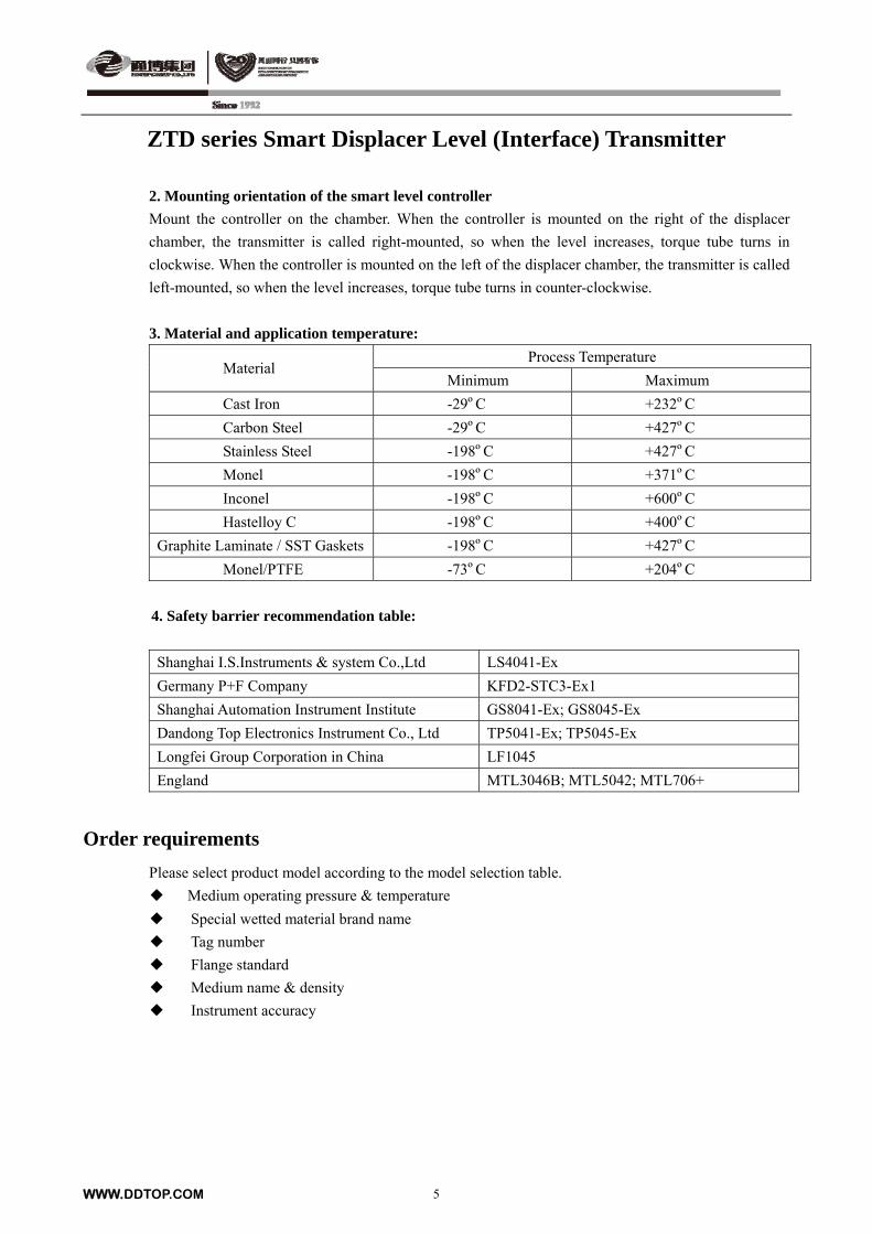
3. Material and application temperature:
Process Temperature Material
Minimum Maximum
Cast Iron -29ºC +232ºC
Carbon Steel -29ºC +427ºC
Stainless Steel -198ºC +427ºC
Monel -198ºC +371ºC
Inconel -198ºC +600ºC
Hastelloy C -198ºC +400ºC
Graphite Laminate / SST Gaskets -198ºC +427ºC
Monel/PTFE -73ºC +204ºC
4. Safety barrier recommendation table:
Shanghai I.S.Instruments & system Co.,Ltd LS4041-Ex
Germany P+F Company KFD2-STC3-Ex1
Shanghai Automation Instrument Institute GS8041-Ex; GS8045-Ex
Dandong Top Electronics Instrument Co., Ltd TP5041-Ex; TP5045-Ex
Longfei Group Corporation in China LF1045
England MTL3046B; MTL5042; MTL706+
Order requirements
Please select product model according to the model selection table.
Medium operating pressure & temperature
Special wetted material brand name
Tag number
Flange standard
Medium name & density
Instrument accuracy
ZTD-G Smart Displacer Level (Interface) Transmitter
Summary
ZTD-G Smart Displacer Level (Interface) Transmitter is a product
developed by Dandong Top Electronics Instrument Co., Ltd , the technicians
research for many years and accumulate lots of experience, absorb the
advantages of inland & foreign product, the performance can reach
international leading level now. ZTD-G Smart Displacer Level (Interface)
Transmitter can be used to measure level, interface or density, output signal
of 4-20mA +HART. By using compatible HART Communicator, not only
can you check, configure, calibrate, or test the smart level transmitter, but
also you can receive the messages from a single controlling loop and
download the information from site into control system.
Operation principle
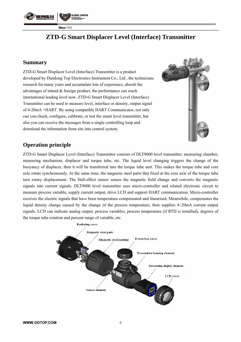
ZTD-G Smart Displacer Level (Interface) Transmitter consists of DLT9000 level transmitter, measuring chamber,
measuring mechanism, displacer and torque tube, etc. The liquid level changing triggers the change of the
buoyancy of displacer, then it will be transferred into the torque tube unit. This makes the torque tube and core
axle rotate synchronously. At the same time, the magnetic steel parts that fixed at the core axle of the torque tube
turn rotary displacement. The Hall-effect sensor senses the magnetic field change and converts the magnetic
signals into current signals. DLT9000 level transmitter uses micro-controller and related electronic circuit to
measure process variable, supply current output, drive LCD and support HART communication. Micro-controller
receives the electric signals that have been temperature-compensated and linearised. Meanwhile, compensates the
liquid density change caused by the change of the process temperature, then supplies 4~20mA current output
signals. LCD can indicate analog output, process variables, process temperature (if RTD is installed), degrees of
the torque tube rotation and percent range of variable, etc.
WWW.DDTOP.COM 6
ZTD-G Smart Displacer Level (Interface) Transmitter
Main performances and parameters
Power supply: 12~30V DC; the controller has reverse polarity protection.(when HART is
communicating, the voltage of controller ≥17.75V DC)
Output signal: 4~20 mA DC (Positive direction – the increase of level, interface, or density make
output increase; Negative direction – the increase of level, interface, or density make
output decrease.)
Measuring range: 300mm—2500mm (can also over range)
Nominal pressure: ≤42.0MPa
Nominal diameter: DN40 or as customers’ request
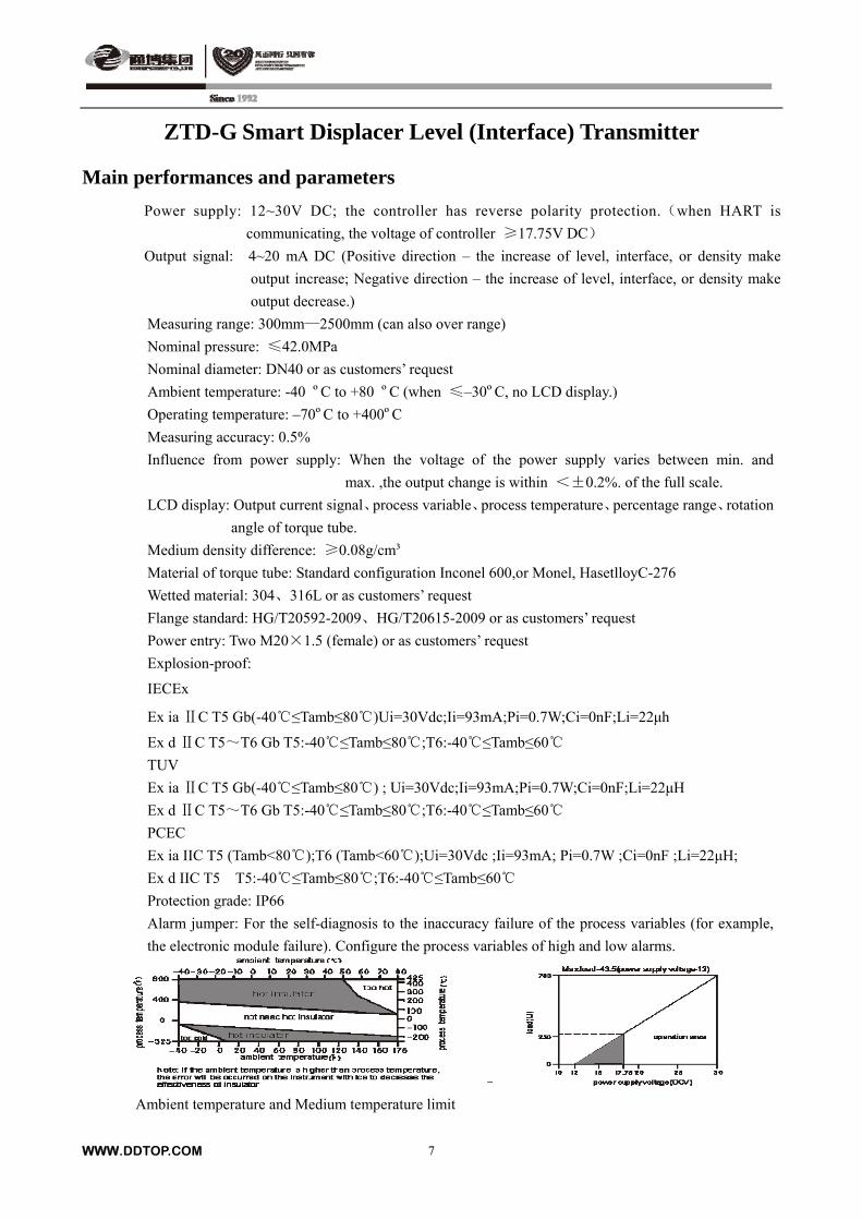
Ambient temperature: -40 ºC to +80 ºC (when ≤–30ºC, no LCD display.)
Operating temperature: –70ºC to +400ºC
Measuring accuracy: 0.5%
Influence from power supply: When the voltage of the power supply varies between min. and
max. ,the output change is within <±0.2%. of the full scale.
LCD display: Output current signal、process variable、process temperature、percentage range、rotation
angle of torque tube.
Medium density difference: ≥0.08g/cm³
Material of torque tube: Standard configuration Inconel 600,or Monel, HasetlloyC-276
Wetted material: 304、316L or as customers’ request
Flange standard: HG/T20592-2009、HG/T20615-2009 or as customers’ request
Power entry: Two M20×1.5 (female) or as customers’ request
Explosion-proof:
IECEx
Ex ia C T5 Gb(Ⅱ -40 ≤Tamb≤80 )Ui=30Vdc;Ii=93mA;Pi=0.7W;Ci=0nF;Li=22 μh
Ex d C T5Ⅱ ~T6 Gb T5:-40 ≤Tamb≤80 ;T6: -40 ≤Tamb≤60
TUV
Ex ia C T5 Gb(Ⅱ -40 ≤Tamb≤80 ) ; Ui=30Vdc;Ii=93mA;Pi=0.7W;Ci=0nF;Li=22μH
Ex d C T5Ⅱ ~T6 Gb T5:-40 ≤Tamb≤80 ;T6: -40 ≤Tamb≤60
PCEC
Ex ia IIC T5 (Tamb<80);T6 (Tamb<60);Ui=30Vdc ;Ii=93mA; Pi=0.7W ;Ci=0nF ;Li=22μH;
Ex d IIC T5 T5:-40 ≤Tamb≤80 ;T6: -40 ≤Tamb≤60
Protection grade: IP66
Alarm jumper: For the self-diagnosis to the inaccuracy failure of the process variables (for example,
the electronic module failure). Configure the process variables of high and low alarms.
–
Ambient temperature and Medium temperature limit
WWW.DDTOP.COM 7
WWW.DDTOP.COM 8
ZTD-G Smart Displacer Level (Interface) Transmitter
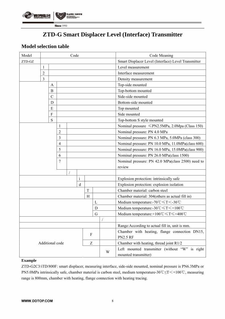
Model selection table
Model Code Code Meaning
ZTD-GZ Smart Displacer Level (Interface) Level Transmitter
1 Level measurement
2 Interface measurement
3 Density measurement
A Top-side mounted
B Top-bottom mounted
C Side-side mounted
D Bottom-side mounted
E Top mounted
F Side mounted
S Top-bottom S style mounted
1 Nominal pressure ≤PN2.5MPa, 2.0Mpa (Class 150)
2 Nominal pressure: PN 4.0 MPa
3 Nominal pressure: PN 6.3 MPa, 5.0MPa (class 300)
4 Nominal pressure: PN 10.0 MPa, 11.0MPa(class 600)
5 Nominal pressure: PN 16.0 MPa, 15.0MPa(class 900)
6 Nominal pressure: PN 26.0 MPa(class 1500)
7 Nominal pressure: PN 42.0 MPa(class 2500) need to
review
/
i Explosion protection: intrinsically safe
d Explosion protection: explosion isolation
T Chamber material: carbon steel
H Chamber material: 304(others as actual fill in)
L Medium temperature:-70≤T<-30
D Medium temperature:-30≤T<+100
G Medium temperature:+100≤T≤+400
/
Range:According to actual fill in, unit is mm.
F Chamber with heating, flange connection DN15,
PN2.5 RF
Z Chamber with heating, thread joint R1/2 Additional code
W
Left mounted transmitter (without “W” is right
mounted transmitter)
Example
ZTD-G2C3/iTD/800F: smart displacer, measuring interface, side-side mounted, nominal pressure is PN6.3MPa or
PN5.0MPa intrinsically safe, chamber material is carbon steel, medium temperature-30≤T<+100, measuring
range is 800mm, chamber with heating, flange connection with heating tracing.
ZTD-G Smart Displacer Level (Interface) Transmitter
Outline and installation dimension
1. The structure and size
H in following chart is measuring range, nominal pressure ≤6.3Mpa. Size in bracket is product with heat
insulation sleeve.
WWW.DDTOP.COM 9
ZTD-G Smart Displacer Level (Interface) Transmitter
WWW.DDTOP.COM 10
WWW.DDTOP.COM 11
ZTD-G Smart Displacer Level (Interface) Transmitter
2. Mounting orientation of the smart level controller
Mount the controller on the chamber. When the controller is mounted on the right of the displacer chamber, the
transmitter is called right-mounted, so when the level increases, torque tube turns in clockwise. When the
controller is mounted on the left of the displacer chamber, the transmitter is called left-mounted, so when the level
increases, torque tube turns in counter-clockwise.
3. Material and application temperature:
Process temperature Material
Minimum Maximum
Cast Iron -29ºC +232ºC
Steel -29ºC +427ºC
Stainless Steel -198ºC +427ºC
Monel -198ºC +371ºC
Inconel -198ºC +600ºC
Hastelloy C -198ºC +400ºC
Graphite Laminate/SST Gaskets -198ºC +427ºC
Monel/PTFE -73ºC +204ºC
4. Safety barrier recommendation table:
Shanghai I.S.Instruments & system Co.,Ltd LS4041-Ex
Germany P+F Company KFD2-STC3-Ex1
Shanghai Automation Instrument Institute GS8041-Ex; GS8045-Ex
Dandong Top Electronics Instrument Co., Ltd TP5041-Ex; TP5045-Ex
Longfei Group Corporation in China LF1045
England MTL3046B; MTL5042; MTL706+
Order requirements
Please select product model according to the model selection table.
Medium operating pressure & temperature
Special wetted material brand name
Tag number
Flange standard
Medium name & density
Instrument accuracy
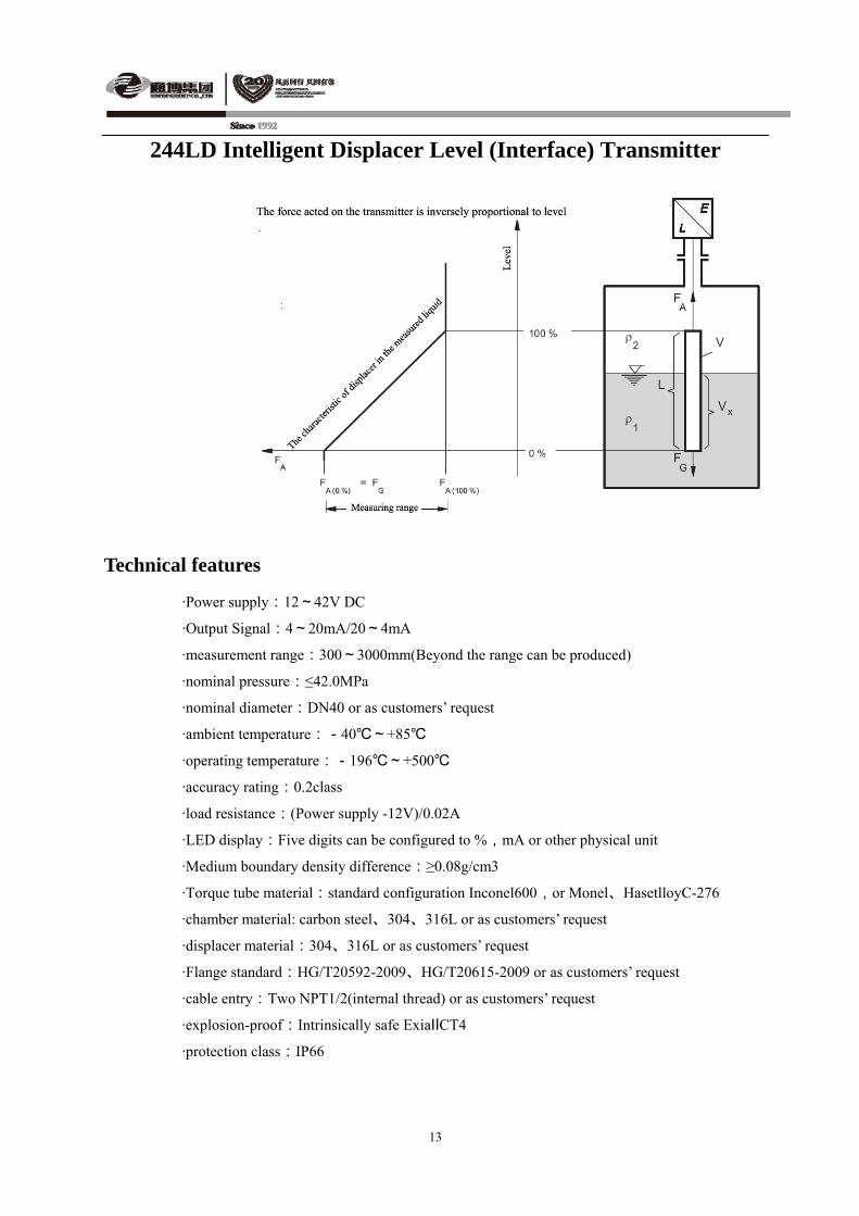
244LD Intelligent Displacer Level (Interface) Transmitter Summary
244LD intelligent displacer level (interface) level transmitter is designed based on Archimedes Buoyancy Principle. It can be used for measuring liquid level, interface and density. The latest model of FDT/DTM technology can provide online calibration and diagnosis, durable in use. A wide range of material selection is suitable for different medium environment. 244LD intelligent displacer level (interface) transmitter in extreme temperature and pressure conditions can be reliable work. This Transmitter is available for any dangerous application. 244LD intelligent displacer level (interface) transmitter is manufactured by Dandong Top Electronics Instrument (Group) Co. Ltd and FOXBORO, The transmitting head and other important parts are original products supplied by FOXBORO, the finished products are as per the original factory standard (FOXBORO).
Operating Principle
The buoyancy of displacer 4 is transmitted to the sensor 3 via lever 1 and the torque tube 2. In measuring range, the voltage is proportional to the buoyancy, and as the input signal is transmitted to the electronic amplifier. Through the electronic amplifier, voltage is converted to 4-20 mA two-wires output signal. In the two-wires system mode, amplifier is powered by the signal current circuit. Any part of the displacer immersed in liquid is adhering to the principle of Archimedes. By measuring buoyancy change of cylindrical displacer suspended in liquid, you can measure the liquid level, interface level or density. When measuring the density and interface level, the displacer should be completely immersed in liquid. The change of the liquid level must be in range area. The calculation of buoyancy: FA= VX·ρ1·g+( V -VX) ·ρ2·g
In the formula:FA:Buoyancy
V:The volume of the displacer
VX:In the liquid density of ρ1, the medium volume displacer swaps out
ρ1:The average of the heavy medium density
ρ2:The average of the lighter medium density
g:The local acceleration of gravity
FG: Buoy its own gravity
12
244LD Intelligent Displacer Level (Interface) Transmitter
Technical features
·Power supply:12~42V DC
·Output Signal:4~20mA/20~4mA
·measurement range:300~3000mm(Beyond the range can be produced)
·nominal pressure:≤42.0MPa
·nominal diameter:DN40 or as customers’ request
·ambient temperature:-40~+85
·operating temperature:-196~+500
·accuracy rating:0.2class
·load resistance:(Power supply -12V)/0.02A
·LED display:Five digits can be configured to %,mA or other physical unit
·Medium boundary density difference:≥0.08g/cm3
·Torque tube material:standard configuration Inconel600,or Monel、HasetlloyC-276
·chamber material: carbon steel、304、316L or as customers’ request
·displacer material:304、316L or as customers’ request
·Flange standard:HG/T20592-2009、HG/T20615-2009 or as customers’ request
·cable entry:Two NPT1/2(internal thread) or as customers’ request
·explosion-proof:Intrinsically safe ExiaⅡCT4
·protection class:IP66
13
WWW.DDTOP.COM 14
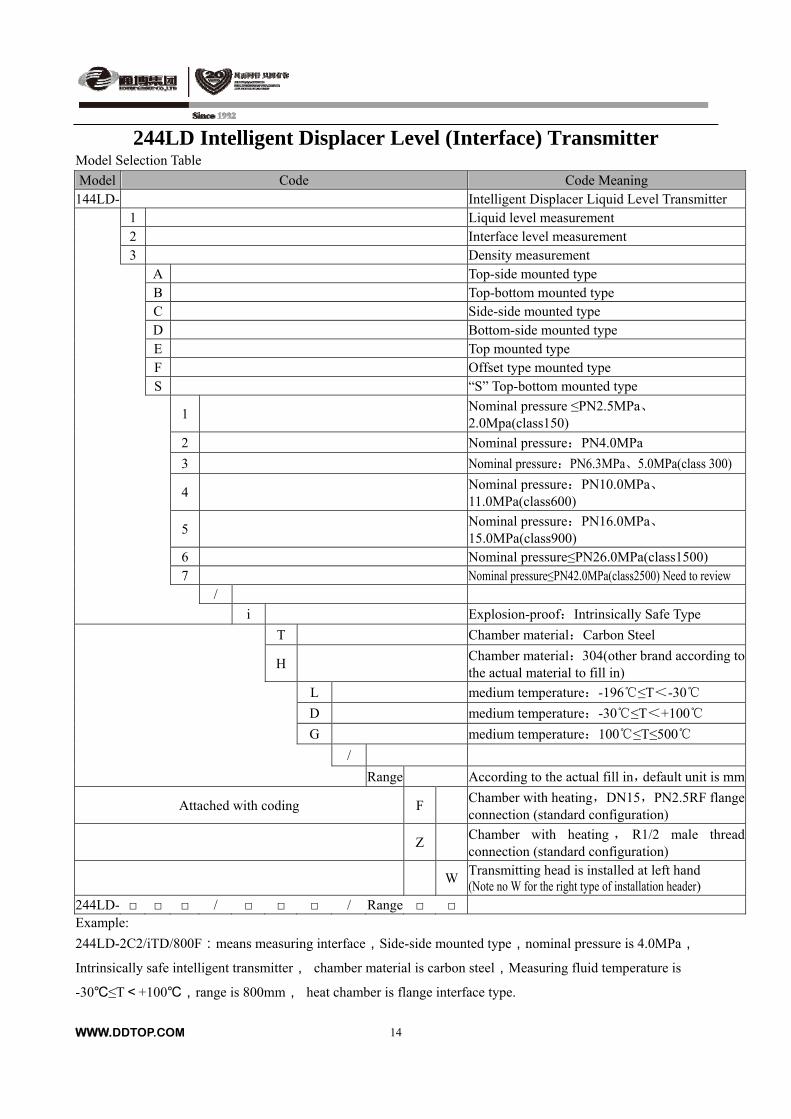
244LD Intelligent Displacer Level (Interface) Transmitter Model Selection Table
Model Code Code Meaning 144LD- Intelligent Displacer Liquid Level Transmitter
1 Liquid level measurement 2 Interface level measurement
3 Density measurement A Top-side mounted type B Top-bottom mounted type C Side-side mounted type D Bottom-side mounted type E Top mounted type F Offset type mounted type
S “S” Top-bottom mounted type
1 Nominal pressure ≤PN2.5MPa、2.0Mpa(class150)
2 Nominal pressure:PN4.0MPa
3 Nominal pressure:PN6.3MPa、5.0MPa(class 300)
4 Nominal pressure:PN10.0MPa、11.0MPa(class600)
5 Nominal pressure:PN16.0MPa、15.0MPa(class900)
6 Nominal pressure≤PN26.0MPa(class1500) 7 Nominal pressure≤PN42.0MPa(class2500) Need to review /
i Explosion-proof:Intrinsically Safe Type
T Chamber material:Carbon Steel
H Chamber material:304(other brand according to the actual material to fill in)
L medium temperature:-196≤T<-30
D medium temperature:-30≤T<+100
G medium temperature:100≤T≤500
/
Range According to the actual fill in,default unit is mm
Attached with coding F Chamber with heating,DN15,PN2.5RF flange connection (standard configuration)
Z Chamber with heating , R1/2 male thread connection (standard configuration)
WTransmitting head is installed at left hand (Note no W for the right type of installation header)
244LD- / / Range Example:
244LD-2C2/iTD/800F:means measuring interface,Side-side mounted type,nominal pressure is 4.0MPa,Intrinsically safe intelligent transmitter, chamber material is carbon steel,Measuring fluid temperature is
-30≤T<+100,range is 800mm, heat chamber is flange interface type.

244LD Intelligent Displacer Level (Interface) Transmitter
Outline drawing and installation
1. The structure and size
H is the range in the picture below,nominal pressure≤PN6.3MPa .
A top-side mounted type B Top-bottom mounted type C Side-side mounted type
D Bottom-side mounted type E Top mounted type
WWW.DDTOP.COM 15
244LD Intelligent Displacer Level (Interface) Transmitter
2 The Installation orientation of smart level controller
Assemble the intelligent level controller to measuring chamber of displacer. Right type of
installation is Controller installed on right of the displacer, torque tube rotates clockwise when
liquid level rises. Left type of installation is Controller installed on the left of the displacer,
torque tube rotates clockwise when liquid level rises.
3 Material and temperature
Process temperature
material Min. Max.
cast iron -29 232
steel -29 427
stainless steel -198 427
Monel -198 371
Inconel -198 600
hastelloy C -198 400
graphite flake/stainless steel gasket -198 427
Monel / P.T.F.E -73 204
4 safety
Safety barrier recommendation table:
Shanghai I.S.Instruments & system Co.,Ltd LS4041-Ex
Germany P+F company KFD2-STC3- Ex1
Shanghai Automation Instrument Institute GS8041- Ex GS8045- Ex
Dandong Top Electronics Instrument (Group) Co.,Ltd. TP5041- Ex TP5045- Ex
Longfei Group Corporation in China LF1045
England MTL3046B MTL5042 MTL706+
Ordering instruction
According to Model Selection Table select operating pressure and temperature Special wetted material grades
Instrument installation tag No.
Flange standard
Name and density of medium
Instrument accuracy grade
WWW.DDTOP.COM 16
UQD Ball Float Level Transmitter
Summary
UQD Ball Float Level Transmitter consists of measurement part and signal controller part.
According to structural features, the measurement part can be divided into 90 type with small
angle, 91type with big angle, 92 type with external float. The signal controller part can be
divided into analog type (UQD.A) and intelligent type (UQD.Z).They are perfect instruments
for liquid level measurement in production process in petroleum, chemical, metallurgy, power
industry and so on.
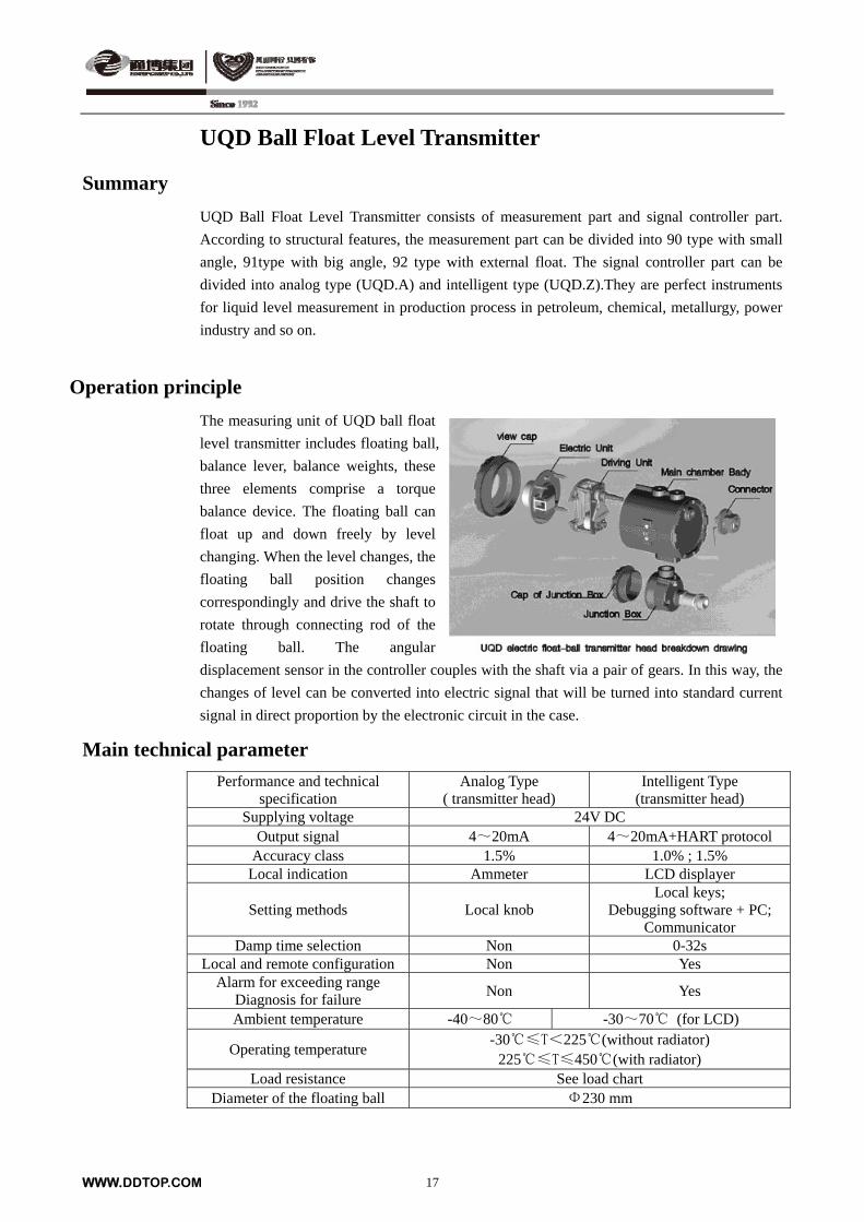
Operation principle
The measuring unit of UQD ball float
level transmitter includes floating ball,
balance lever, balance weights, these
three elements comprise a torque
balance device. The floating ball can
float up and down freely by level
changing. When the level changes, the
floating ball position changes
correspondingly and drive the shaft to
rotate through connecting rod of the
floating ball. The angular
displacement sensor in the controller couples with the shaft via a pair of gears. In this way, the
changes of level can be converted into electric signal that will be turned into standard current
signal in direct proportion by the electronic circuit in the case.
Main technical parameter
Performance and technical specification
Analog Type ( transmitter head)
Intelligent Type (transmitter head)
Supplying voltage 24V DC Output signal 4~20mA 4~20mA+HART protocol
Accuracy class 1.5% 1.0% ; 1.5% Local indication Ammeter LCD displayer
Setting methods Local knob Local keys;
Debugging software + PC; Communicator
Damp time selection Non 0-32s Local and remote configuration Non Yes
Alarm for exceeding range Diagnosis for failure
Non Yes
Ambient temperature -40~80 -30~70 (for LCD)
Operating temperature -30≤T<225(without radiator)
225≤T≤450(with radiator) Load resistance See load chart
Diameter of the floating ball Φ230 mm
WWW.DDTOP.COM 17
WWW.DDTOP.COM 18
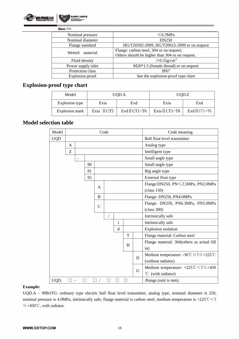
Nominal pressure ≤6.3MPa Nominal diameter DN250 Flange standard HG/T20592-2009, HG/T20615-2009 or on request
Wetted material Flange: carbon steel, 304 or on request; Others should be higher than 304 or on request.
Fluid density ≥0.55g/cm3 Power supply inlet M20*1.5 (female thread) or on request
Protection class IP67 Explosion-proof See the explosion-proof type chart
Explosion-proof type chart
Model UQD.A UQD.Z
Explosion type Exia Exd Exia Exd
Explosion mark Exia ⅡCT5 ExdⅡCT1~T6 ExiaⅡCT1~T6 ExdⅡCT1~T6
Model selection table
Model Code Code meaning
UQD Ball float level transmitter
A Analog type
Z Intelligent type
- Small angle type
90 Small angle type
91 Big angle type
92 External float type
A Flange:DN250, PN≤2.5MPa, PN2.0MPa
(class 150)
B Flange: DN250, PN4.0MPa
C Flange: DN250, PN6.3MPa, PN5.0MPa
(class 300)
/ Intrinsically safe
i Intrinsically safe
d Explosion isolation
T Flange material: Carbon steel
H
Flange material: 304(others as actual fill
in)
DMedium temperature: -30≤T≤+225
(without radiator)
GMedium temperature: +225<T≤+450
(with radiator)
UQD. - / /Range (unit is mm)
Example:
UQD.A – 90B/iTG: ordinary type electric ball float level transmitter, analog type, nominal diameter is 250,
nominal pressure is 4.0MPa, intrinsically safe, flange material is carbon steel, medium temperature is +225<T
≤+450, with radiator.
UQD Ball Float Level Transmitter
Outline and installation dimensions
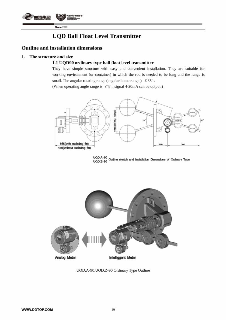
1. The structure and size 1.1 UQD90 ordinary type ball float level transmitter They have simple structure with easy and convenient installation. They are suitable for
working environment (or container) in which the rod is needed to be long and the range is
small. The angular rotating range (angular home range ) ≤35。
.
(When operating angle range is ≥8。, signal 4-20mA can be output.)
UQD.A-90,UQD.Z-90 Ordinary Type Outline
WWW.DDTOP.COM 19
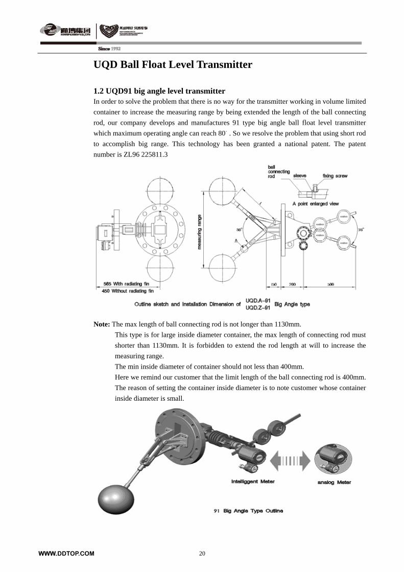
UQD Ball Float Level Transmitter 1.2 UQD91 big angle level transmitter In order to solve the problem that there is no way for the transmitter working in volume limited
container to increase the measuring range by being extended the length of the ball connecting
rod, our company develops and manufactures 91 type big angle ball float level transmitter
which maximum operating angle can reach 80。. So we resolve the problem that using short rod
to accomplish big range. This technology has been granted a national patent. The patent
number is ZL96 225811.3
Note: The max length of ball connecting rod is not longer than 1130mm.
This type is for large inside diameter container, the max length of connecting rod must
shorter than 1130mm. It is forbidden to extend the rod length at will to increase the
measuring range.
The min inside diameter of container should not less than 400mm.
Here we remind our customer that the limit length of the ball connecting rod is 400mm.
The reason of setting the container inside diameter is to note customer whose container
inside diameter is small.
WWW.DDTOP.COM 20
UQD Ball Float Level Transmitter
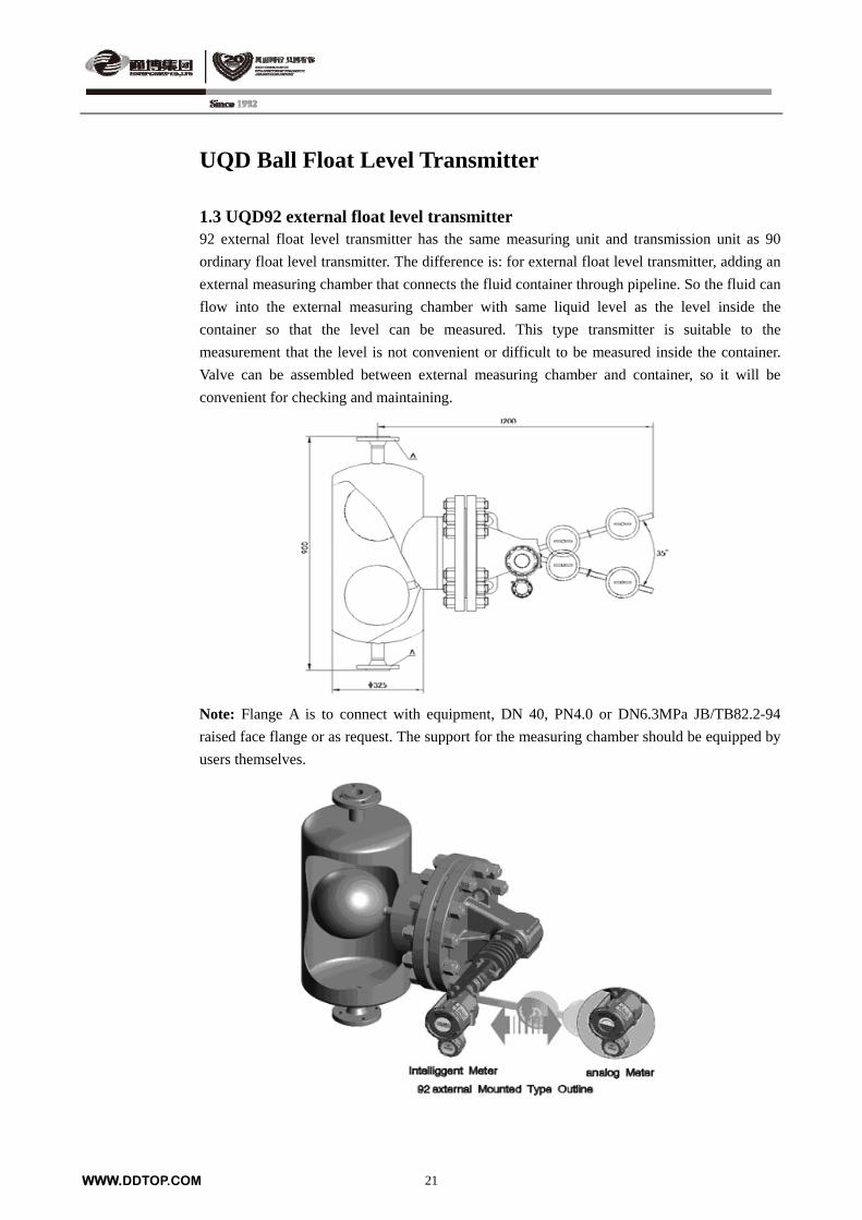
1.3 UQD92 external float level transmitter 92 external float level transmitter has the same measuring unit and transmission unit as 90
ordinary float level transmitter. The difference is: for external float level transmitter, adding an
external measuring chamber that connects the fluid container through pipeline. So the fluid can
flow into the external measuring chamber with same liquid level as the level inside the
container so that the level can be measured. This type transmitter is suitable to the
measurement that the level is not convenient or difficult to be measured inside the container.
Valve can be assembled between external measuring chamber and container, so it will be
convenient for checking and maintaining.
Note: Flange A is to connect with equipment, DN 40, PN4.0 or DN6.3MPa JB/TB82.2-94
raised face flange or as request. The support for the measuring chamber should be equipped by
users themselves.
WWW.DDTOP.COM 21
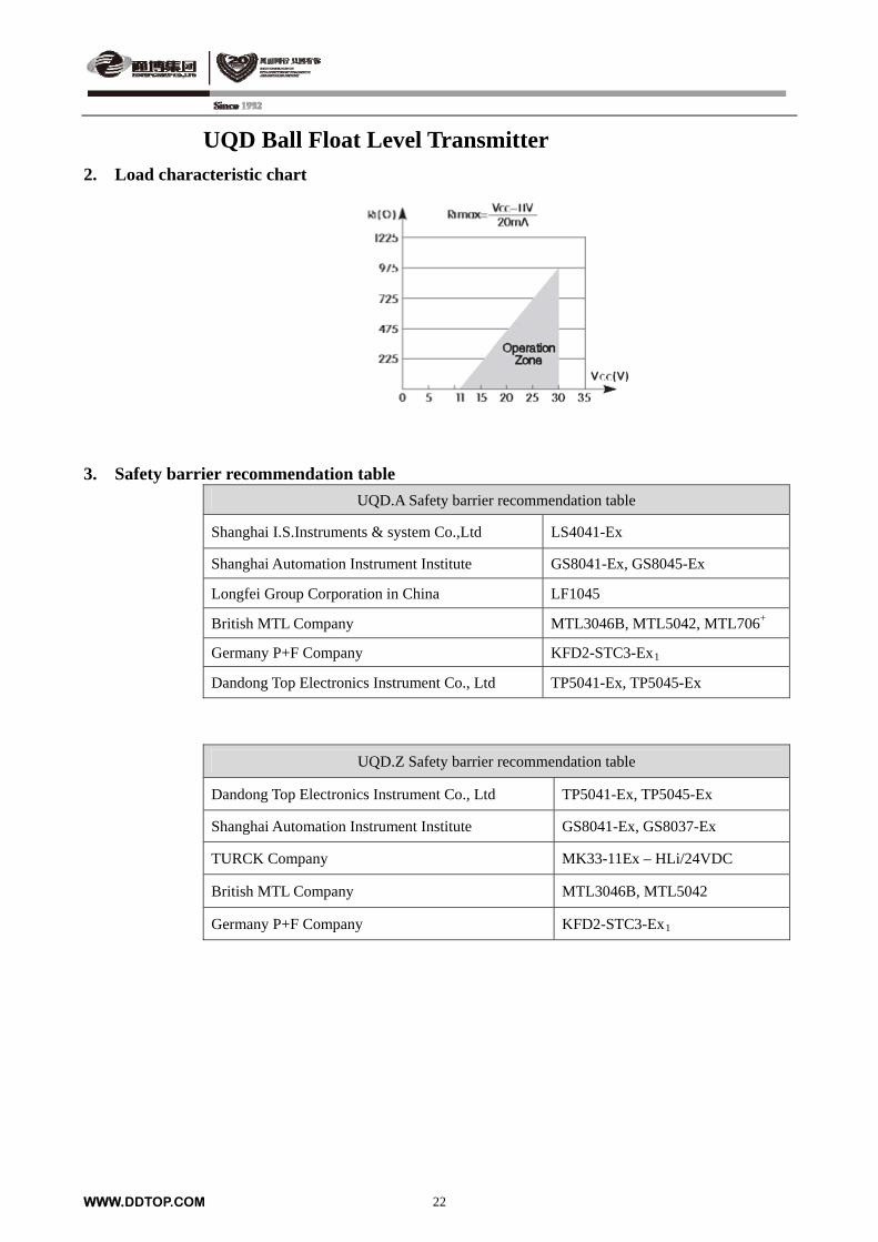
UQD Ball Float Level Transmitter 2. Load characteristic chart
3. Safety barrier recommendation table
UQD.A Safety barrier recommendation table
Shanghai I.S.Instruments & system Co.,Ltd LS4041-Ex
Shanghai Automation Instrument Institute GS8041-Ex, GS8045-Ex
Longfei Group Corporation in China LF1045
British MTL Company MTL3046B, MTL5042, MTL706+
Germany P+F Company KFD2-STC3-Ex1
Dandong Top Electronics Instrument Co., Ltd TP5041-Ex, TP5045-Ex
UQD.Z Safety barrier recommendation table
Dandong Top Electronics Instrument Co., Ltd TP5041-Ex, TP5045-Ex
Shanghai Automation Instrument Institute GS8041-Ex, GS8037-Ex
TURCK Company MK33-11Ex – HLi/24VDC
British MTL Company MTL3046B, MTL5042
Germany P+F Company KFD2-STC3-Ex1
WWW.DDTOP.COM 22
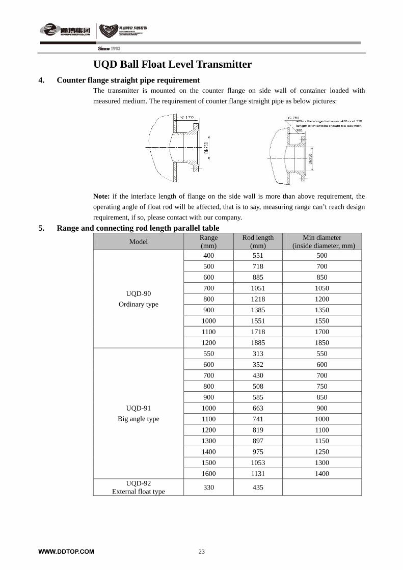
UQD Ball Float Level Transmitter 4. Counter flange straight pipe requirement
The transmitter is mounted on the counter flange on side wall of container loaded with
measured medium. The requirement of counter flange straight pipe as below pictures:
Note: if the interface length of flange on the side wall is more than above requirement, the
operating angle of float rod will be affected, that is to say, measuring range can’t reach design
requirement, if so, please contact with our company.
5. Range and connecting rod length parallel table
Model Range (mm)
Rod length (mm)
Min diameter (inside diameter, mm)
400 551 500
500 718 700
600 885 850
700 1051 1050
800 1218 1200
900 1385 1350
1000 1551 1550
1100 1718 1700
UQD-90
Ordinary type
1200 1885 1850
550 313 550
600 352 600
700 430 700
800 508 750
900 585 850
1000 663 900
1100 741 1000
1200 819 1100
1300 897 1150
1400 975 1250
1500 1053 1300
UQD-91
Big angle type
1600 1131 1400 UQD-92
External float type 330 435
WWW.DDTOP.COM 23
WWW.DDTOP.COM 24
Order requirements
Please select product model according to the model selection table.
Medium operating pressure & temperature
Special wetted material brand name
Tag number
Flange standard
Medium name & density
Instrument accuracy

UHC, UQC Series Magnetic Float Level Transmitter
Summary
UHC series magnetic float level transmitter and UQC series
magnetic ball float level transmitter are new designed
generation level indicator according to magnetic coupling
principle. They present the level indication directly and
clearly with advanced technology and the proper structure
and are suitable for petroleum, chemical, power, light
industry and pharmaceutical industrial field, etc. UHC series
magnetic float level transmitter is mounted on side of vessels,
while UQC series magnetic ball float level transmitter is
mounted on the top of vessels, especially for the
measurement of the underground storage tanks.
Operation principle
UHC series magnetic float level transmitter and UQC series
magnetic ball float level transmitter are composed of body part
and local indicator. UHC series magnetic float level transmitter
is mounted and connected on the side of vessels. When the float
moves up and down with the level (interface) changing, the
magnet steel inside float drives the magnetic flakes inside of the
indicator to roll over. All the magnetic flakes are coated with
red one side and white another side (liquid is red, air is white).
The continuous red or white zone can clearly indicate actual
level or interface inside of vessels. While UQC series magnetic
ball float level transmitter is mounted on the top of vessels.
With the level or interface changing, the ball float will move up
and down and drive the magnetic connecting rod going up and
down. The magnet steel inside of the connecting rod drives the
magnetic flakes inside of the indicator to roll over. All the
magnetic flakes are coated with red one side and white another
side (liquid is red, air is white). The continuous red or white
zone can clearly indicate actual level or interface inside of
vessels. If equip with remote transducer and upper/lower alarms,
the UHC, UQC series transmitters can realize remotely
transmitting the level signal and automatically controlling.
WWW.DDTOP.COM 25
WWW.DDTOP.COM 26
UHC, UQC Series Magnetic Float Level Transmitter
Main technical parameter 1. Local indicator unit
1.1 UHC ordinary magnetic float level transmitter Application range: This level transmitter is the most frequently used side-mounted magnetic
float level transmitter, is suitable for level measuring which the liquid
medium PN ≤ 6.3MPa and the operating temperature ≤ 300.
Range: 300mm ~ 6000mm (increasing the range can be manufactured specially)
Nominal pressure: 10MPa ~ 16MPa
Nominal diameter: DN25 (or on request)
Ambient temperature: -40 ~ +80
Operating temperature: ≤300
Measuring accuracy: ±5mm
Medium density: Level: ρ≥0.45g/cm³; Interface: ρ1-ρ2 ≥0.16g/cm³
Wetted material: 304, 316L or on request
Flange standard: HG/T20592-2009, HG/T20615-2009 or on request
1.2 UHC.GY high pressure magnetic float level transmitter Application range: this level transmitter is frequently used in high pressure environment, is
suitable for level measuring which the liquid medium PN between 10MPa
and 16MPa and the operating temperature ≤ 300.
Range: 300mm ~ 6000mm (increasing the range can be manufactured specially)
Nominal pressure: 10MPa ~ 16MPa
Nominal diameter: DN25 (on request)
Ambient temperature: -40 ~ +80
Operating temperature: ≤300
Measuring accuracy: ±5mm
Medium density: Level: ρ≥0.5g/cm³; Interface: ρ1-ρ2 ≥0.16g/cm³
Wetted material: 304, 316L or on request
Flange standard: HG/T20592-2009, HG/T20615-2009 or on request
1.3 UHC.GW high temperature magnetic float level transmitter Application range: this level transmitter is frequently used in high temperature environment,
is suitable for level measuring which the liquid medium of PN ≤ 11MPa
and the operating temperature between +300 ~ +450.
Range: 300mm ~ 6000mm (increasing the range can be manufactured specially)
Nominal pressure: ≤11.0MPa
Nominal diameter: DN25 (on request)
Ambient temperature: -40 ~ +80
Operating temperature: +300 ~ +450
Measuring accuracy: ±5mm
Medium density: Level: ρ≥0.5g/cm³; Interface: ρ1-ρ2 ≥0.16g/cm³
WWW.DDTOP.COM 27
UHC, UQC Series Magnetic Float Level Transmitter Wetted material: 304, 316L or on request
Flange standard: HG/T20592-2009, HG/T20615-2009 or on request
1.4 UHC.F antirot magnetic float level transmitter Application range: Chamber 304 interior liner PTFE, this transmitter is suitable for
measuring level for petrol and chemical industry while with of strong
corrosion occasion.
Range: 300mm ~ 6000mm
Nominal pressure: ≤2.5MPa
Nominal diameter: DN25 (or on request)
Ambient temperature: -40 ~ +80
Operating temperature: -30 ~ +200
Measuring accuracy: ±5mm
Medium density: Level: ρ≥0.5g/cm³; Interface: ρ1-ρ2 ≥0.16g/cm³
Wetted material: chamber 304 interior liner PTFE, float PTFE
Flange standard: HG/T20592-2009, HG/T20615-2009 or on request
1.5 UHC.O vacuum jacket magnetic float level transmitter Application range: this level transmitter is suitable to measure liquid medium for low
temperature and easy to frost occasion.
Range: 300mm ~ 6000mm
Nominal pressure: ≤6.3MPa
Nominal diameter: DN25 (or on request)
Ambient temperature: -40 ~ +80
Operating temperature: -196 ~ 0
Measuring accuracy: ±5mm
Medium density: Level: ρ≥0.5g/cm³; Interface: ρ1-ρ2 ≥0.16g/cm³
Wetted material: 304, 316L or on request
Flange standard: HG/T20592-2009, HG/T20615-2009 or on request
1.6 UQC magnetic ball float level transmitter Application range: this level transmitter is suitable to measure liquid medium for
underground tank and container that is difficult to open flank.
Range: 0mm ~ 4000mm
Nominal pressure: ≤2.5MPa
Nominal diameter: DN150
Ambient temperature: -40 ~ +80
Operating temperature: -40 ~ +300
Measuring accuracy: ±5mm
Medium density: Level: ρ≥0.5g/cm³; Interface: ρ1-ρ2 ≥0.16g/cm³
Wetted material: 304, 316L or on request
Flange standard: HG/T20592-2009, HG/T20615-2009 or on request
WWW.DDTOP.COM 28
UHC, UQC Series Magnetic Float Level Transmitter
2. Remote unit Remote transmitter is divided into two forms, one is reed-resistance remote level transmitter, and the other is magnetostrictive remote level transmitter.
2.1 Reed-resistance remote level transmitter Remote transmitter is binded on outside of chamber. When float moves up and down with level changes, reed switch corresponding to level will pull in under the action of float magnetic field, so that resistance and current will change, transduction circuit will be transferred into signal of 4-20mA DC to realize remoting. Range: 300mm-6000mm (increasing the range can be manufactured specially) Power supply: 24V DC Output signal: DC 4mA-20mA Ambient temperature: -40 - +80 Operating temperature: -40 - +120 Measuring accuracy: ±5mm Power supply inlet: M20 x 1.5 (female thread) or on request Explosion-proof: ExdⅡCT4-T6, ExiaⅡCT4-T6
Protection class: IP67 2.2 Magnetostrictive remote level transmitter Remote transmitter is binded on outside of chamber. There is a magnetostrictive line in remote
measuring pipe. Through sensor circuit which is controlled by microprocessor, the equipment launches current pulse along magnetostrictive line, thereby, generates toroidal magnetic field around magnetostrictive line. The magnetic steel inside of float magnetize magnetostrictive line along axial direction. Stacking place of two magnetic fields will generate a reverse pulse, this pulse will transmit to top of sensor along magnetostrictive line, the transmitting time of pulse will be captured and calculated by circuit unit to get the position of float. Range: 300mm-6000mm (increasing the range can be manufactured specially) Power supply: 24V DC Output signal: DC 4mA-20mA + HART Ambient temperature: -40 - +80 Operating temperature: -40 - +450 Measuring accuracy: ±5mm Protection class: IP68 Power supply inlet: M20 x 1.5 (female thread) Explosion-proof: Explosion isolation type: ExdⅡCT4-T6
Intrinsically safe type: ExiaⅡCT4-T6 3. Upper, lower limit alarm It is assembled on outside of chamber and can adjust position at will. Output signal: one is normal open, one is normal close Ambient temperature: -40-+80
Working life: ≥105 times Protection class: IP67 Power supply inlet: M20 x 1.5 (female thread) or on request Measuring accuracy: ±5mm Contact capacity: AC200VA, DC50W
WWW.DDTOP.COM 29
UHC, UQC Series Magnetic Float Level Transmitter
Model selection table
Model Code Code meaning
UHC- Magnetic float level transmitter
UHC.GY- High pressure magnetic float level transmitter
UHC.GW- High temperature magnetic float level transmitter
UHC.F- Antirot magnetic float level transmitter
UHC.O- Vacuum jacket magnetic float level transmitter
UQC- Magnetic ball float level transmitter
M With local indicator
N Without local indicator
S With reed-resistance remote level transmitter
U With magnetostrictive remote level transmitter
T Without remote level transmitter
A With upper or lower limit alarm
C With upper and lower limit alarms
D Without alarm
E PN1.0MPa
F PN1.6MPa
G PN2.5MPa
J PN4.0MPa
H PN6.3MPa
O PN10MPa
P PN16MPa
Q Other pressure class
* Level ρ or interface ρ1 /ρ2
-
* Measuring range. For UQC, please note the neck length.
d Explosion isolation
i Intrinsically safe
Additional code W With steam jacket (ZG1/2” male thread)
L1 Vent valve above
L2 Blow-down valve below
L3 Vent valve above and blow-down valve below
- -
Note: If PN is higher than above table, please refer to model selection table to choose a similar model according to actual request. Example: UHC-MSCF0.8/0.5-1800dWL2 magnetic float liquid level indicator, with local indicator, with reed-resistance remote level transmitter (non-intelligent), with upper and lower limit alarms, nominal pressure 1.6MPa, measuring interface, medium densities are 0.8g/cm3 and 0.5g/cm3 , measuring range is 1800mm, Explosion isolation, with steam jacket and blow-down valve below.
UHC, UQC Series Magnetic Float Level Transmitter
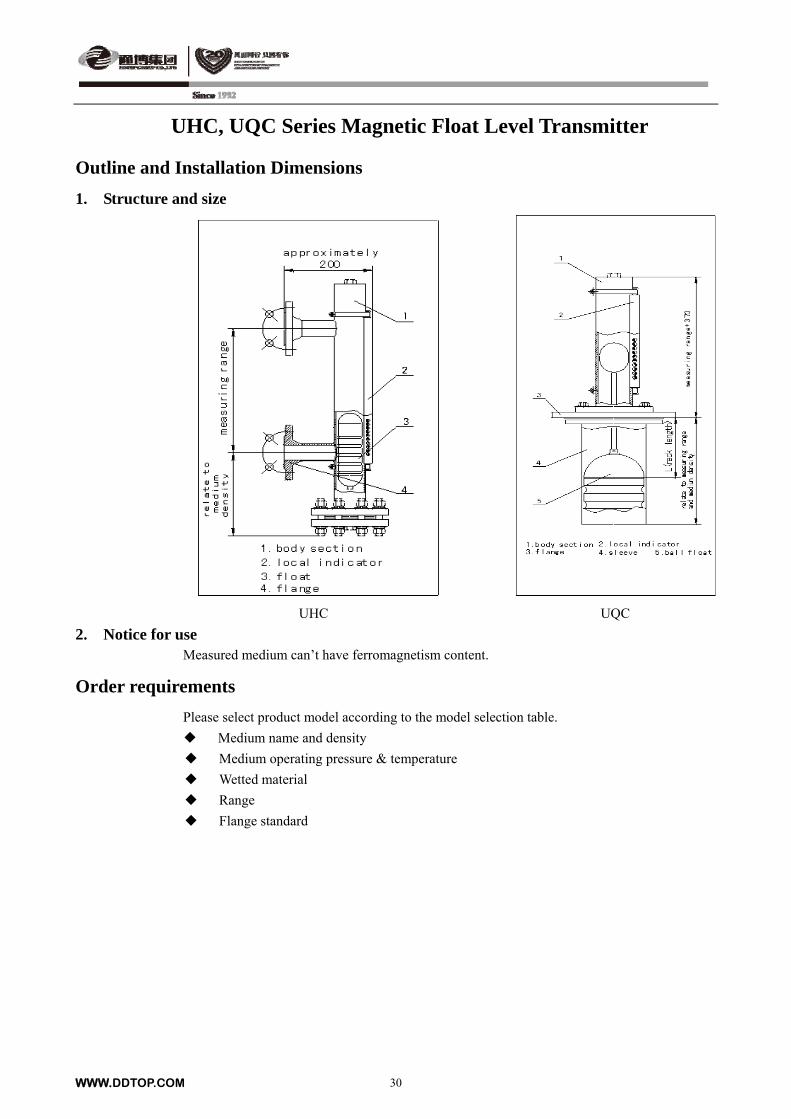
Outline and Installation Dimensions
1. Structure and size
UHC UQC
2. Notice for use Measured medium can’t have ferromagnetism content.
Order requirements
Please select product model according to the model selection table.
Medium name and density
Medium operating pressure & temperature
Wetted material
Range
Flange standard
WWW.DDTOP.COM 30
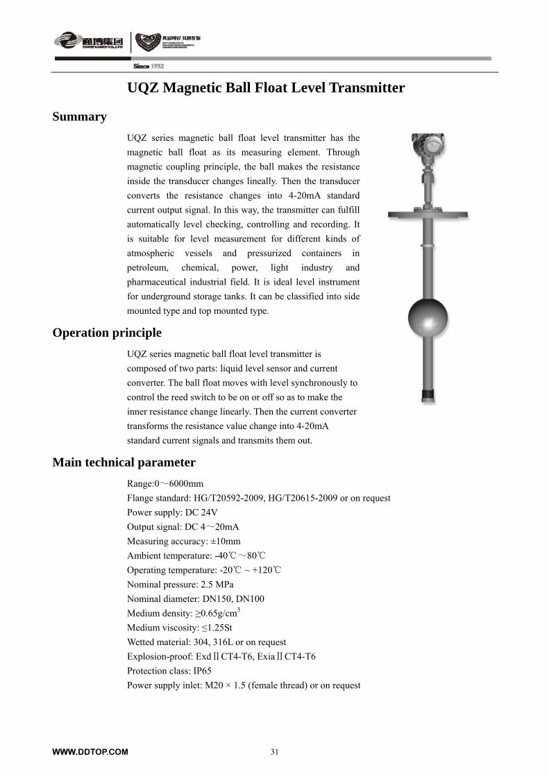
UQZ Magnetic Ball Float Level Transmitter
Summary
UQZ series magnetic ball float level transmitter has the
magnetic ball float as its measuring element. Through
magnetic coupling principle, the ball makes the resistance
inside the transducer changes lineally. Then the transducer
converts the resistance changes into 4-20mA standard
current output signal. In this way, the transmitter can fulfill
automatically level checking, controlling and recording. It
is suitable for level measurement for different kinds of
atmospheric vessels and pressurized containers in
petroleum, chemical, power, light industry and
pharmaceutical industrial field. It is ideal level instrument
for underground storage tanks. It can be classified into side
mounted type and top mounted type.
Operation principle
UQZ series magnetic ball float level transmitter is
composed of two parts: liquid level sensor and current
converter. The ball float moves with level synchronously to
control the reed switch to be on or off so as to make the
inner resistance change linearly. Then the current converter
transforms the resistance value change into 4-20mA
standard current signals and transmits them out.
Main technical parameter
Range:0~6000mm
Flange standard: HG/T20592-2009, HG/T20615-2009 or on request
Power supply: DC 24V
Output signal: DC 4~20mA
Measuring accuracy: ±10mm
Ambient temperature: -40~80
Operating temperature: -20 ~ +120
Nominal pressure: 2.5 MPa
Nominal diameter: DN150, DN100
Medium density: ≥0.65g/cm3
Medium viscosity: ≤1.25St
Wetted material: 304, 316L or on request
Explosion-proof: ExdⅡCT4-T6, ExiaⅡCT4-T6
Protection class: IP65
Power supply inlet: M20 × 1.5 (female thread) or on request
WWW.DDTOP.COM 31
UQZ Magnetic Ball Float Level Transmitter
Model selection table
Model Code Code meaning
UQZ- Magnetic ball float level transmitter
01 Top mounted
02 Side mounted
-
* Range (please note the neck length when choose 01)
d Explosion isolation
i Intrinsically safe
UQZ-
Example:
UQZ-01-2000d (neck length: 1000mm) magnetic ball float liquid level transmitter, top
mounted, measuring range 2000mm, explosion isolation, neck length: 1000mm.
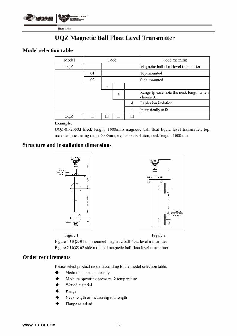
Structure and installation dimensions
Figure 1 Figure 2
Figure 1 UQZ-01 top mounted magnetic ball float level transmitter
Figure 2 UQZ-02 side mounted magnetic ball float level transmitter
Order requirements
Please select product model according to the model selection table.
Medium name and density
Medium operating pressure & temperature
Wetted material
Range
Neck length or measuring rod length
Flange standard
WWW.DDTOP.COM 32
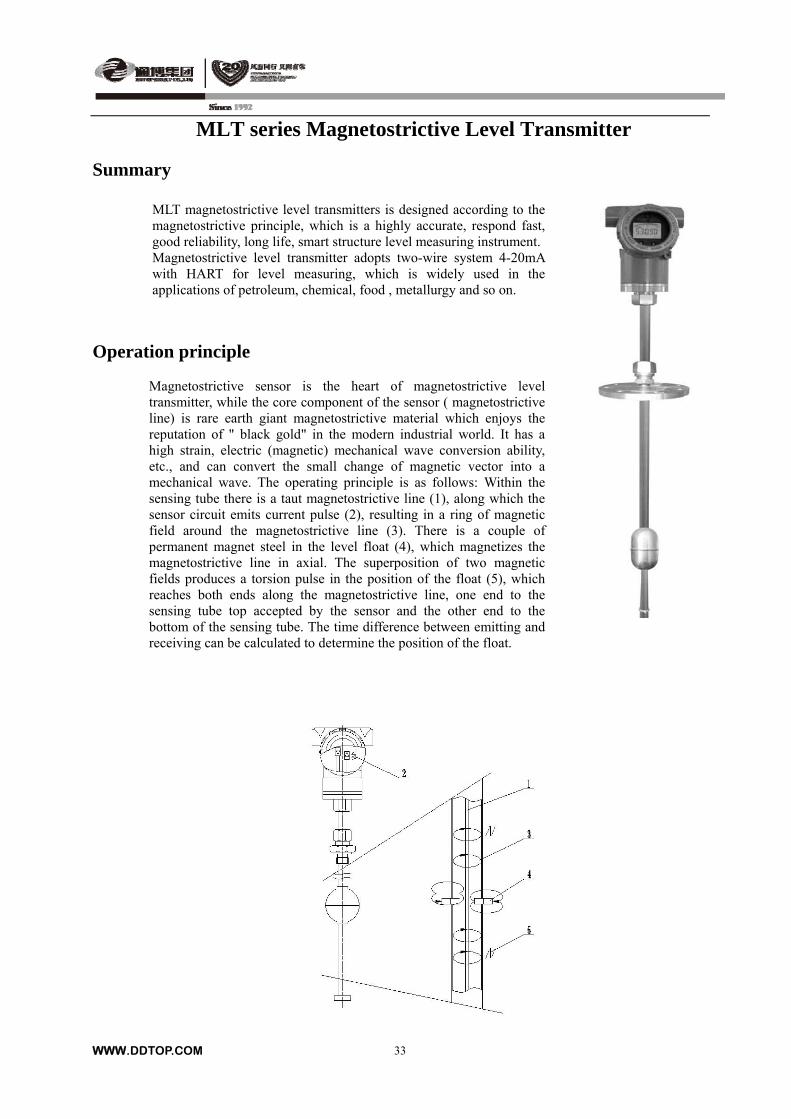
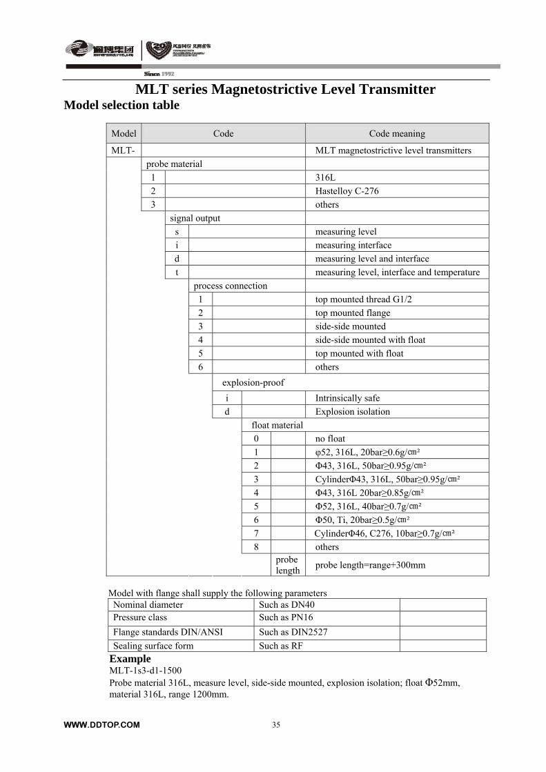
MLT series Magnetostrictive Level Transmitter Summary
MLT magnetostrictive level transmitters is designed according to the magnetostrictive principle, which is a highly accurate, respond fast, good reliability, long life, smart structure level measuring instrument. Magnetostrictive level transmitter adopts two-wire system 4-20mA with HART for level measuring, which is widely used in the applications of petroleum, chemical, food , metallurgy and so on.
Operation principle
Magnetostrictive sensor is the heart of magnetostrictive level transmitter, while the core component of the sensor ( magnetostrictive line) is rare earth giant magnetostrictive material which enjoys the reputation of " black gold" in the modern industrial world. It has a high strain, electric (magnetic) mechanical wave conversion ability, etc., and can convert the small change of magnetic vector into a mechanical wave. The operating principle is as follows: Within the sensing tube there is a taut magnetostrictive line (1), along which the sensor circuit emits current pulse (2), resulting in a ring of magnetic field around the magnetostrictive line (3). There is a couple of permanent magnet steel in the level float (4), which magnetizes the magnetostrictive line in axial. The superposition of two magnetic fields produces a torsion pulse in the position of the float (5), which reaches both ends along the magnetostrictive line, one end to the sensing tube top accepted by the sensor and the other end to the bottom of the sensing tube. The time difference between emitting and receiving can be calculated to determine the position of the float.
WWW.DDTOP.COM
33
WWW.DDTOP.COM
34
MLT series Magnetostrictive Level Transmitter
Main technical parameters
Power supply: 9 ~ 28V DC Output signal: 4 to 20mA+HART Range: 40mm ~4000mm Probe diameter: Φ12mm Operating pressure: ≤5.0MPa Medium temperature: -40 ~ +160 Ambient temperature: -40 ~ +80 Accuracy: ±1mm Resolution: ≤0.1mm Temperature influence: ≤±0.01%/ Min. density difference: 0.5g/cm³ Wetted material: 316L, Hastelloy C-276 (or on request) Process connection: G1/2″, standard flange (or on request) or others Power supply inlet: M20×1.5 (female thread) Explosion-proof: Intrinsically safe Ex ia IIBT5/T6 Ga;
Explosion isolation Ex d IICT3/T6 Gb Protection class: IP67
Float specification table (PTFE coating optional):
Float specification Material Max. operating pressure (bar)
Medium density (g/cm³)
Ball Φ52 316L 20.0 ≥0.60
Ball Φ43 316L 50.0 ≥0.95
Cylinder Φ43 316L 16.0 ≥0.70
Ball Φ43 316L 20.0 ≥0.85
Ball Φ52 316L 40.0 ≥0.70
Ball Φ50 Ti 20.0 ≥0.50
Cylinder Φ46 C-276 10.0 ≥0.70
WWW.DDTOP.COM
35
MLT series Magnetostrictive Level Transmitter Model selection table
Model Code Code meaning
MLT- MLT magnetostrictive level transmitters
probe material
1 316L
2 Hastelloy C-276
3 others
signal output
s measuring level
i measuring interface
d measuring level and interface
t measuring level, interface and temperature
process connection
1 top mounted thread G1/2
2 top mounted flange
3 side-side mounted
4 side-side mounted with float
5 top mounted with float
6 others
explosion-proof
i Intrinsically safe
d Explosion isolation
float material
0 no float
1 φ52, 316L, 20bar≥0.6g/²
2 Φ43, 316L, 50bar≥0.95g/²
3 CylinderΦ43, 316L, 50bar≥0.95g/²
4 Φ43, 316L 20bar≥0.85g/²
5 Φ52, 316L, 40bar≥0.7g/²
6 Φ50, Ti, 20bar≥0.5g/²
7 CylinderΦ46, C276, 10bar≥0.7g/²
8 others
probe length
probe length=range+300mm
Model with flange shall supply the following parameters
Nominal diameter Such as DN40 Pressure class Such as PN16
Flange standards DIN/ANSI Such as DIN2527
Sealing surface form Such as RF Example MLT-1s3-d1-1500 Probe material 316L, measure level, side-side mounted, explosion isolation; float Φ52mm, material 316L, range 1200mm.

MLT series Magnetostrictive Level Transmitter
Outline and installation dimension Structure and size
Order requirements
a. If process connection is flange connection, you must provide the following parameters: Nominal diameter\Pressure class\Flange standard (Indicated in the selection); b. Confirm the bottom fixed mode: none, heavy punch or hook; c. According to the corrosivity of the medium to be measured to determine the probe rod material; d. If you need to order the float, also need to provide the density range of the measured upper medium and lower medium, so that we can help you to select the float model.
WWW.DDTOP.COM
36
WWW.DDTOP.COM
37
GWLF Guided Wave Radar Level (Interface) Transmitter
Summary
GWLF can be used for measuring level or interface with
4-20mA standard current signal output. The measuring
accuracy is not affected by change of density or dielectric
constant of medium (in the setting range). It is easy operating
and maintenance. It only needs to be entered configuration
data into the instrument and no need to change the liquid
level at field. So, GWLF is a new type of level (interface)
measuring instrument.
Operation principle
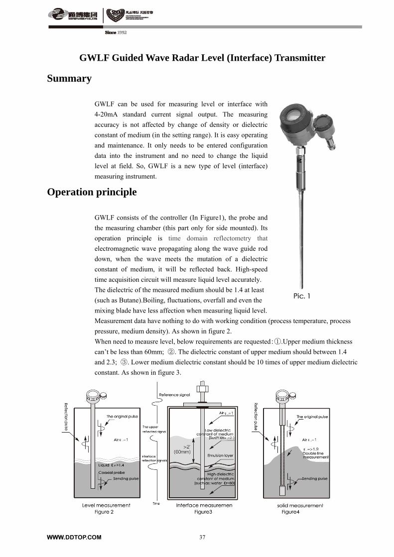
GWLF consists of the controller (In Figure1), the probe and
the measuring chamber (this part only for side mounted). Its
operation principle is time domain reflectometry that
electromagnetic wave propagating along the wave guide rod
down, when the wave meets the mutation of a dielectric
constant of medium, it will be reflected back. High-speed
time acquisition circuit will measure liquid level accurately.
The dielectric of the measured medium should be 1.4 at least
(such as Butane).Boiling, fluctuations, overfall and even the
mixing blade have less affection when measuring liquid level.
Measurement data have nothing to do with working condition (process temperature, process
pressure, medium density). As shown in figure 2.
When need to meausre level, below requirements are requested:①.Upper medium thickness
can’t be less than 60mm; ②. The dielectric constant of upper medium should between 1.4
and 2.3; ③. Lower medium dielectric constant should be 10 times of upper medium dielectric
constant. As shown in figure 3.
WWW.DDTOP.COM
38
GWLF Guided Wave Radar Level Transmitter
Main technical parameter 1. Parameters of controller
Output signal: 4 ~ 20mA or 4 ~ 20mA + HART, applicable within 3.8 ~ 20.5mA Resolution: Analog: 0.01mA, Display: 1mm Accuracy: 5mm or 0.1% FS for coaxial probe Range: 600mm ~ 6000mm or 1000mm ~ 22000mm Load resistance: Max. 650Ω(24VDC) Damp: 0-32s adjustable Diagnostic alarm: 3.6mA, 22mA, hold (Note: when both HART protocol and field indicator
are selected, 3.6mA diagnose is not available.) User interface: 3 keys, LCD or HART communication Ambient temperature: -40 ~ 70 (LCD operating temperature: -20 ~ 70) Power supply inlet: M20×1.5 or RC1/2 (female thread) 1/2″NPT (female thread) 3/4″NPT (female thread) Enclosure material: Aluminum Explosion-proof: Intrinsically safe Ex ia II CT2-T6
Explosion isolation + Intrinsically safe Exd (ia) II CT2-T6
2. Parameters for probes
Probe type GWPB-A Coaxial
GWPB-B Twin-rod
GWPB-C Mono- rod
Process temperature -196 ≤ T ≤ +430 -40 ≤ T ≤ +200 -40 ≤ T ≤ +315
Nominal pressure Temperature& pressure curve
Temperature& pressure curve
Temperature& pressure curve
Recommended application Universal application, clean liquid with low viscosity
Universal application with little medium-sticking
Universal application and foam
Non-recommend application With medium-sticking, scaling and concentrated foam
Scaling on the isolator Dielectric constant <10
Dielectric constant range 1.4 - 100 1.9 - 100 10 - 100
Max. viscosity 500CP 1500CP 8000CP
Probe material (standard) 316L 316L 316L
Optional probe material Hastelloy, Monel Hastelloy, Monel Hastelloy, Monel
Seal material PTFE/PEEK PTFE/PEEK PTFE/PEEK
Process connection (Recommended)
NPT3/4 NPT2 NPT2
Optional process connection R3/4 or flange R2 or flange R2 or flange
Length of probe 600mm ~6100mm 600mm ~6100mm 600mm ~6100mm
Blind zone (upper) 0 0 60mm
Non-linearity zone (upper) 180mm 180mm
Non-linearity zone (lower) 120mm 120mm 50mm Distance (from probe to wall )
No requirement >100mm >300mm
Non-linearity Zone lower
120mm 120mm 50mm
Distance (from probe to wall )
No requirements 100mm 300mm
Min. neck diameter > Probe diameter Φ100mm Φ150mm
Material level gauging Not suitable Particle Φ≤5mm Particle Φ≤3mm
Foam application Not suitable for
concentrated foam Suitable Suitable
WWW.DDTOP.COM
39
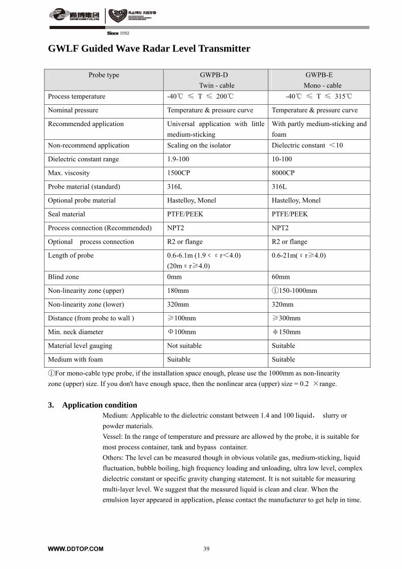
GWLF Guided Wave Radar Level Transmitter
Probe type GWPB-D
Twin - cable
GWPB-E
Mono - cable
Process temperature -40 ≤ T ≤ 200 -40 ≤ T ≤ 315
Nominal pressure Temperature & pressure curve Temperature & pressure curve
Recommended application Universal application with little
medium-sticking
With partly medium-sticking and
foam
Non-recommend application Scaling on the isolator Dielectric constant <10
Dielectric constant range 1.9-100 10-100
Max. viscosity 1500CP 8000CP
Probe material (standard) 316L 316L
Optional probe material Hastelloy, Monel Hastelloy, Monel
Seal material PTFE/PEEK PTFE/PEEK
Process connection (Recommended) NPT2 NPT2
Optional process connection R2 or flange R2 or flange
Length of probe 0.6-6.1m (1.9﹤εr<4.0)
(20mεr≥4.0)
0.6-21m(εr≥4.0)
Blind zone 0mm 60mm
Non-linearity zone (upper) 180mm ①150-1000mm
Non-linearity zone (lower) 320mm 320mm
Distance (from probe to wall ) ≥100mm ≥300mm
Min. neck diameter Φ100mm φ150mm
Material level gauging Not suitable Suitable
Medium with foam Suitable Suitable
①For mono-cable type probe, if the installation space enough, please use the 1000mm as non-linearity
zone (upper) size. If you don't have enough space, then the nonlinear area (upper) size = 0.2 ×range.
3. Application condition Medium: Applicable to the dielectric constant between 1.4 and 100 liquid, slurry or
powder materials.
Vessel: In the range of temperature and pressure are allowed by the probe, it is suitable for
most process container, tank and bypass container.
Others: The level can be measured though in obvious volatile gas, medium-sticking, liquid
fluctuation, bubble boiling, high frequency loading and unloading, ultra low level, complex
dielectric constant or specific gravity changing statement. It is not suitable for measuring
multi-layer level. We suggest that the measured liquid is clean and clear. When the
emulsion layer appeared in application, please contact the manufacturer to get help in time.
WWW.DDTOP.COM
40
GWLF Guided Wave Radar Level Transmitter
Model selection table 1. Controller model selection table
Model Mode Code meaning
GWLK- Guided wave radar level transmitter
M Electronic element: 4~20mA
Z Electronic element: 4~20mA+HART
I Intrinsically safe
Z Explosion isolation + Intrinsically safe
1 Power supply inlet: M20×1.5 (female thread)
2 Power supply inlet: NPT1/2 (female thread)
3 Power supply inlet: Rc1/2 (female thread)
4 Power supply inlet: NPT3/4 (female thread)
GWLK-
2. Probe model selection table Model Code Code meaning
GWPB- Guided wave radar level transmitter probe
A Coaxial probe B Twin-rod probe C Mono-rod probe D Twin-cable probe E Mono-cable probe 0 PN2.0MPa (class 150) 1 PN2.5MPa 2 PN4.0MPa 3 PN6.3MPa (class 300) 4 PN10.0 MPa (class 600) L -196 ≤ process temperature ≤ -40 D -40 ≤ process temperature ≤ 100 F 100 ≤ process temperature ≤ 250 H 250≤ process temperature ≤ 400 V 300≤ process temperature ≤ 430 S Probe material:316 L Probe material: 316L M Probe material: Monel H Probe material: Hastelloy A Probe with PTFE (only for type C) D Process connection: R3/4 (Only for coaxial probe) E Process connection: NPT3/4 (Only for coaxial probe) F Process connection: R2 G Process connection: NPT2 N Process connection: Flange X Process connection: Others - Length of probe (mm) / measuring range (mm) GWPB -
WWW.DDTOP.COM
41
GWLF Guided Wave Radar Level Transmitter
Example for probe selection
Known conditions:
Medium: Light diesel oil; Process pressure: 0.35MPa; Process temperature:120
Range: 800mm; Mounted type: side-side mounted
The 1st step: Confirm the probe model:
Firstly consideration is twin-rod (cable) probe, secondly is coaxial probe (-A, -F), the last is
mono-rod (cable).
For interface measurement, A type probe is not applicable.
To select probe type according to viscosity of medium under application.
Application viscosity<500CP, optional probe : Coaxial –A,-F
500CP≤application viscosity<1500CP, optional probe: twin-rod (cable) –B, –D
1500CP≤application viscosity≤8000CP, optional probe: mono-rod (cable) –C, –E
Current selected probe type: Coaxial type (-A-- -F--)
According to medium of dielectric constant to confirm if the selected probe is suitable for the
application. (Refer to Appendix --- dielectric constant of common medium)
1.4≤dielectric constant<1.9, unsuitable probe: twin-rod (cable):-B,-D, mono- rod (cable):-C,-E
1.9 ≤dielectric constant<10.0 , unsuitable probe: mono-rod (cable):-B,-D
dielectric constant≥10.0, all kinds of probes are available.
The dielectric constant of light diesel oil is 2.1.It can be measured by Coaxial type probe
(-A-- -F--)
Due to liquid level measurement, current option:-A--
The 2nd step: According to process temperature and operating pressure to select pressure grade. (Refer to
process temperature and pressure curve)
Current selection: -A0--
The 3rd step: Confirm temperature range of probe according to process temperature
Current selection: -A0F--
The 4th step: According to causticity of medium to select material of probe
Current selection: -A0F-S-
The 5th step: Confirm process connection of probe:
When adopting top mounting, the process connection of probe is the connection between probe
and tank. For side-side mounting, the process connection of probe means the connection
between probe and external measuring cage, both thread and flange connection are suitable.
For coaxial probe (-A,-F), any process connection in the model selection table can be selected.
For other type probe (-B,-C,-D,-E), due to structure limit, R3/4 or NPT3/4 is not applicable.
Current selection: -A0F-SE-
The 6th step: Confirm the length of probe
Min. length of probe= range + upper non-linearity zone or neck length (select bigger value) +
lower non-linearity zone.
When measuring light diesel oil, the data of non-linearity zone for -A type probe: the upper
blind zone is 180mm, the lower non-linearity zone is 120mm.
Min. length of probe=800+180+120=1100mm
Finally confirmed the length of probe: 1.1m
Finally confirmed model of probe : GWPB-AOF-SE-1.1 (800mm range)
Guided wave radar probe, coaxial probe, nominal pressure 1.0MPa, 100≤process
temperature≤200, probe material 316L, process connection NPT3/4, the length of probe is1.1m.
WWW.DDTOP.COM
42
GWLF Guided Wave Radar Level Transmitter
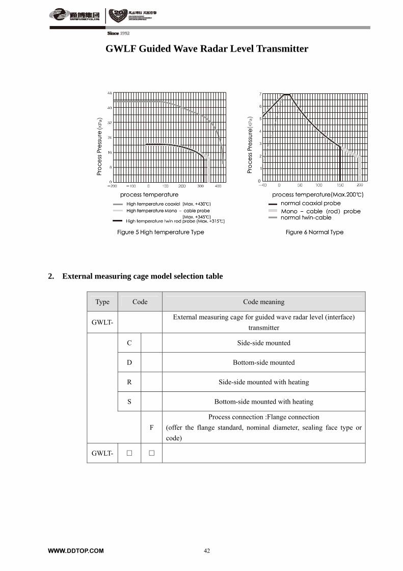
2. External measuring cage model selection table
Type Code Code meaning
GWLT- External measuring cage for guided wave radar level (interface)
transmitter
C Side-side mounted
D Bottom-side mounted
R Side-side mounted with heating
S Bottom-side mounted with heating
F
Process connection :Flange connection
(offer the flange standard, nominal diameter, sealing face type or
code)
GWLT-
WWW.DDTOP.COM
43
GWLF Guided Wave Radar Level Transmitter
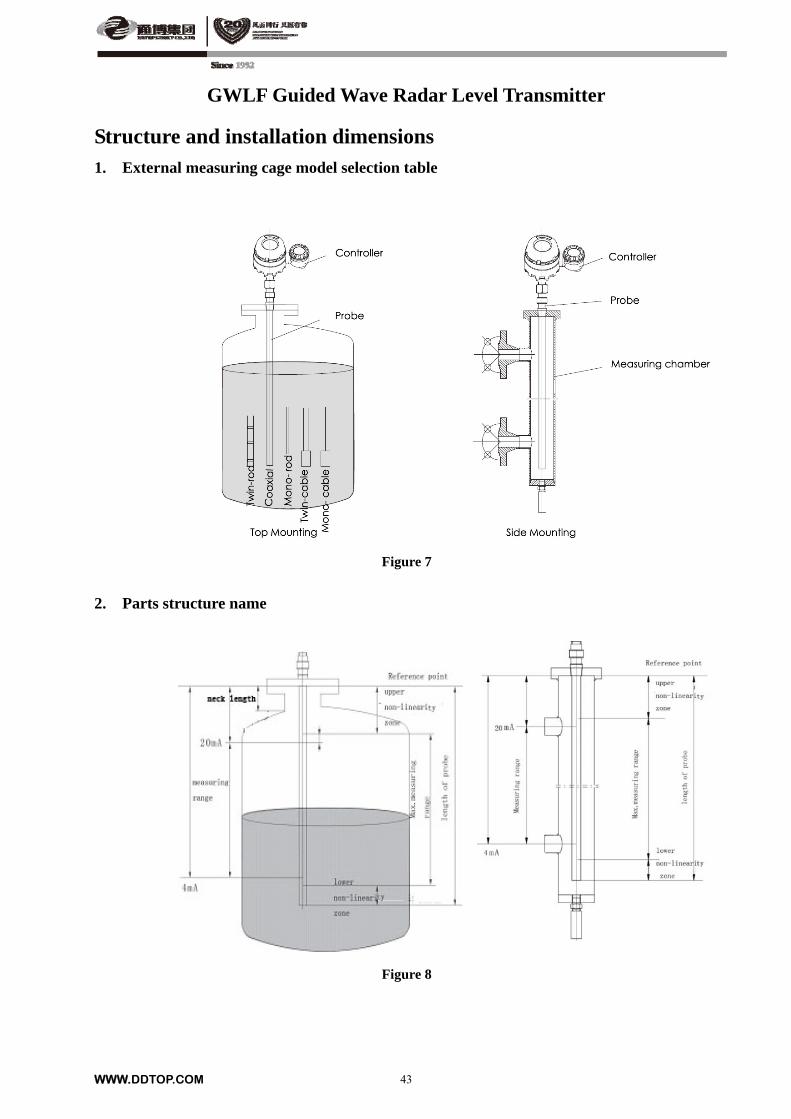
Structure and installation dimensions 1. External measuring cage model selection table
Figure 7
2. Parts structure name
Figure 8
WWW.DDTOP.COM
44
GWLF Guided Wave Radar Level Transmitter
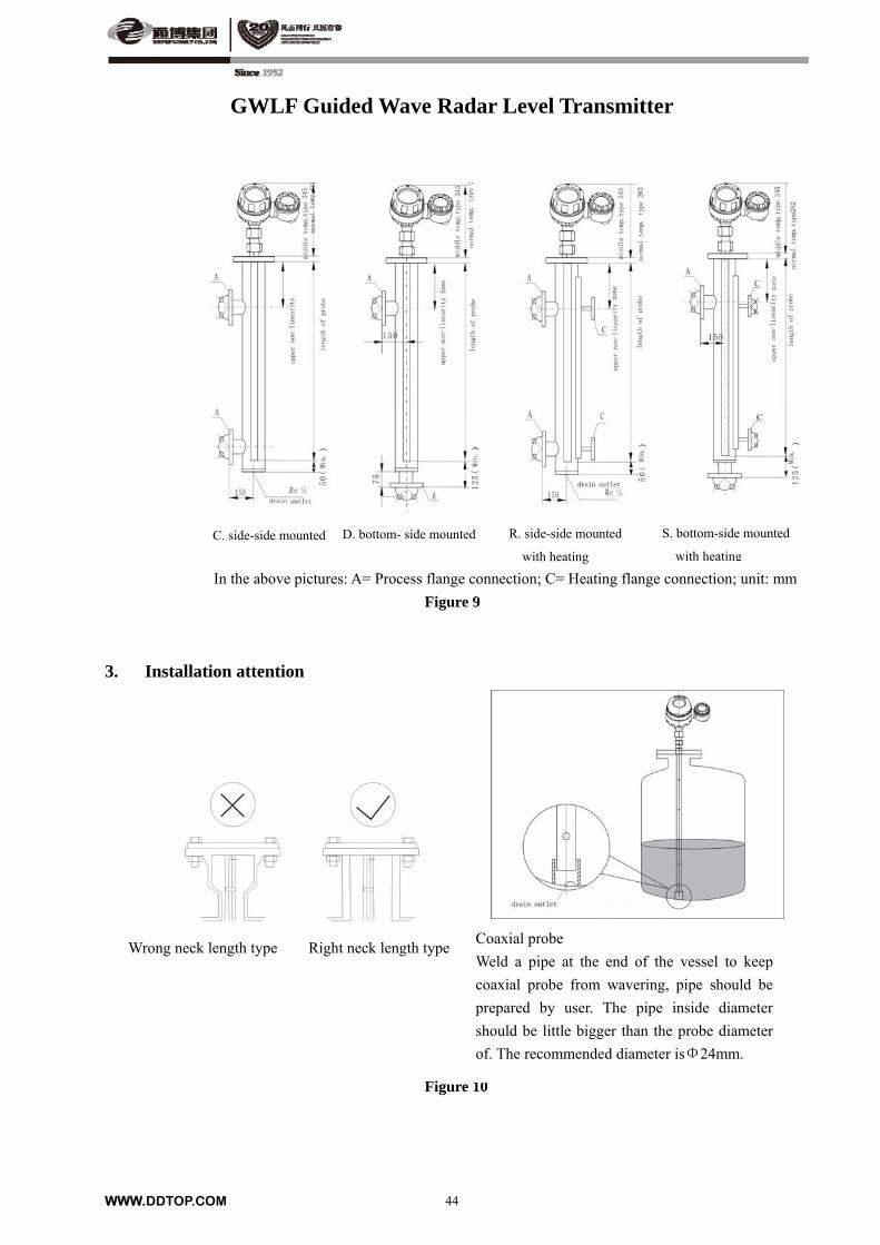
In the above pictures: A= Process flange connection; C= Heating flange connection; unit: mm
R. side-side mounted
with heating
D. bottom- side mounted C. side-side mounted S. bottom-side mounted
with heating
Figure 9
3. Installation attention
Wrong neck type Correct neck type
Wrong neck length type Right neck length type
Figure 10
Coaxial probe
Weld a pipe at the end of the vessel to keep
coaxial probe from wavering, pipe should be
prepared by user. The pipe inside diameter
should be little bigger than the probe diameter
of. The recommended diameter isΦ24mm.
WWW.DDTOP.COM
45
GWLF Guided Wave Radar Level Transmitter
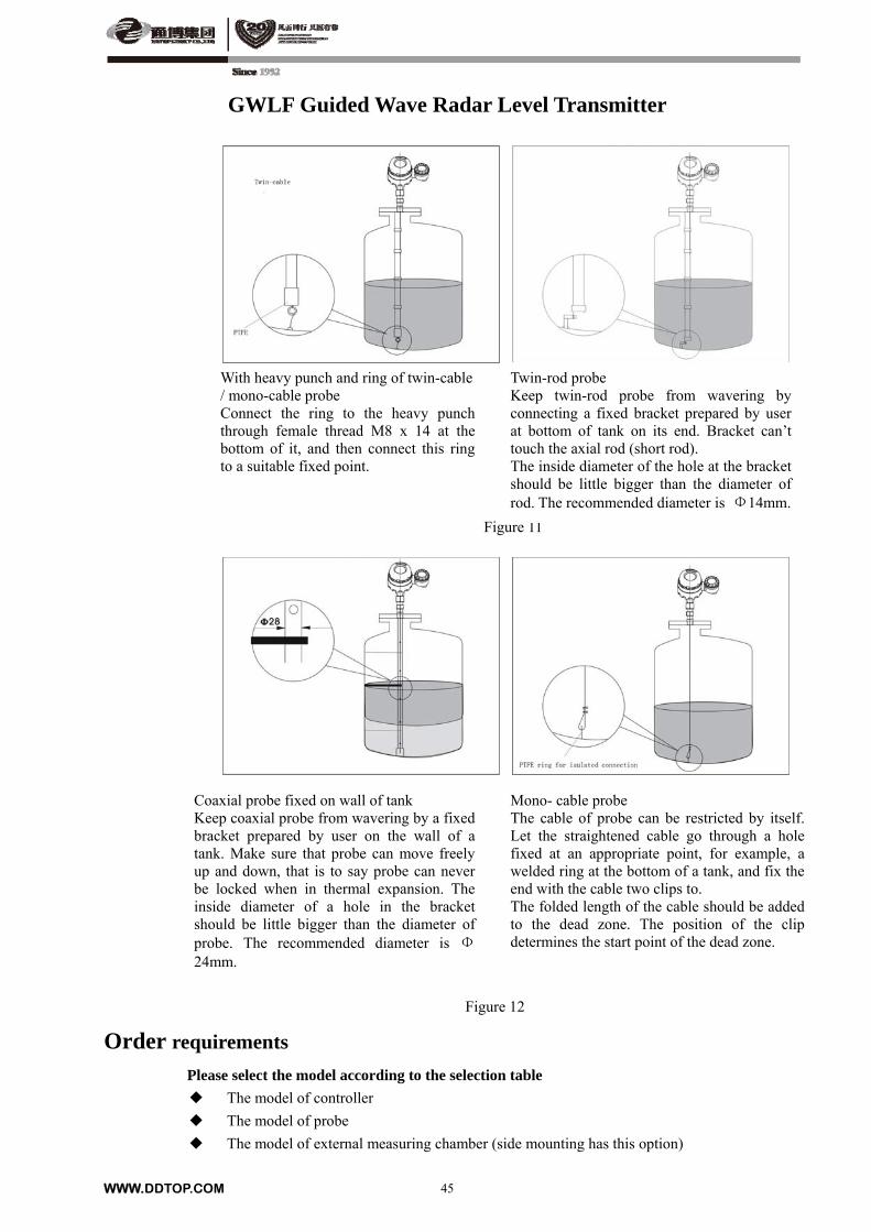
Figure 11
With heavy punch and ring of twin-cable / mono-cable probe Connect the ring to the heavy punch through female thread M8 x 14 at the bottom of it, and then connect this ring to a suitable fixed point.
Twin-rod probe Keep twin-rod probe from wavering by connecting a fixed bracket prepared by user at bottom of tank on its end. Bracket can’t touch the axial rod (short rod). The inside diameter of the hole at the bracket should be little bigger than the diameter of rod. The recommended diameter is Φ14mm.
Coaxial probe fixed on wall of tank Keep coaxial probe from wavering by a fixed bracket prepared by user on the wall of a tank. Make sure that probe can move freely up and down, that is to say probe can never be locked when in thermal expansion. The inside diameter of a hole in the bracket should be little bigger than the diameter of probe. The recommended diameter is Φ24mm.
Mono- cable probe The cable of probe can be restricted by itself. Let the straightened cable go through a hole fixed at an appropriate point, for example, a welded ring at the bottom of a tank, and fix the end with the cable two clips to. The folded length of the cable should be added to the dead zone. The position of the clip determines the start point of the dead zone.
Figure 12
Order requirements Please select the model according to the selection table
The model of controller
The model of probe
The model of external measuring chamber (side mounting has this option)
WWW.DDTOP.COM
46
TRG8060 Radar Level Meter
Summary
TRG8000 radar level meter is independent research and development by DDTOP and is domestic advanced level of liquid level measuring instrument. Among them, the carrier frequency of 26 GHZ TRG8060 radar level meter adopts professional microwave technology, structural design of small beam angle, small antenna size, energy concentration, high reliability and high precision, small measuring blind area, the intelligent signal processing, the advantages of the strong anti-interference ability, is not sensitive to the installation position and obstacles in tank, greatly improve the accuracy of measurement. The radar level meter is suitable for wide temperature, humidity, pressure and other process under the condition of measuring line, widely used in oil refineries and storage tanks, liquefied petroleum gas storage, liquid plant preservation, petroleum and chemical industry, food and beverage industry, water and wastewater treatment, water conservancy and hydropower and other industries.
Operating Principle
TRG8060 radar level meter is two-wire 26 GHZ monopulse radar level meter, transmit energy by antenna with low extremely short pulse, the pulse transmits at the speed of light in the space, met on the surface of measured medium, some of its energy is reflected back, received by the same antenna. Time interval of transmitted pulse and receiving the pulse is proportional to the distance from the antenna to the surface of the measured medium. TRG8060 radar level meter adopts relevant demodulation technology, can accurately identify the transmitted pulse and the reception of the pulse time interval, thus further calculate the antenna to the surface of the measured medium distance.
Technical features
measurement range: 300mm~30000mm accuracy: ±3mm or 0.1%FS (With strong take) Dead zone: 300mm environment temperature: -40~60 Minimum dielectric constant: 1.8 Power supply:(16~36)V DC¹(two-wire system) (16~36)V DC or (198~242)V AC(four-wire system) Explosion-proof:Ex ia IIC T6 Ga (T6:-40≤Ta≤60)
Ui=28Vdc ;Ii=93mA; Pi=0.65W ;Ci=0nF ;Li=0μH; Ex d IIC T6 Gb (T6:-40≤Ta≤60)
Housing/ protection class:Aluminum /IP67;Stainless Steel /IP67 Output Signal:Analog Quantity:4~20mA Digital Quantity:HART 1200 Baud rate frequency shift keying (FSK) modulation signal Electricity resolution ratio:1.6μA Alerting Signal:3.8mA、20.5mA、22mA Status Display:Choosable Display Resolution:0.1mm Temperature Influence:<0.01%/ Transmitting Frequency:26GHz Transmitting Power:≤50μW Overall Power Consumption:Max. 1VA, 1W Structural:Rod antenna TRG8061,As shown in figure 1, Horn antenna TRG8062,As shown in figure 2, Process sealed antenna TRG8063,As shown in figure 3, Parabolic antenna TRG8064,As shown in figure 4.

WWW.DDTOP.COM
47
TRG8060 Radar Level Meter
Model Selection Table
1 TRG8061
Model Code Code Meaning
TRG8061
P Not explosion-proof
I Intrinsically Safe Type(Ex ia IIC T6 Ga)
G Explosion-proof type(Ex d IIC T6 Gb)
F Intrinsically Safe Type + Explosion-proof type
(Ex d[ia]ia IIC T6 Ga)
B Antenna Types/ material/ process temperature:(R Type)
Seal the horn/PTFE/(-40~130)
GP Process connection/material:(F) screw thread G1½A
NP Process connection/material:(F) screw thread NPT1½
FA Process connection/material:(L)flange DN50/PTFE
FX Process connection/material: tailor-made
A Neck length tube:100mm
B Neck length tube:200mm
X Neck length tube: tailor-made
B Electronic Component:
(4~20)mA/(22.8~26.4)V DC /HART/two-wire
C Electronic Component:
(4~20)mA/(16~36)V DC/HART/four-wire
D Electronic Component:
(4~20)mA/(198~242)V AC/HARTfour-wire
A Housing/ protection class: aluminum alloy /IP67
B Housing/ protection class: Stainless Steel 316/IP67
M Cable entry:M20×1.5
N Cable entry:NPT1/2
A Local display/ programming:Yes
X Local display/ programming:No
Note:Intrinsically Safe Type (Ex ia IIC T6 Ga)、Intrinsically Safe Type + Explosion-proof type only
use the“B” Electronic Component and“B”type hosing.
Example:TRG8061GBGPBBAMA
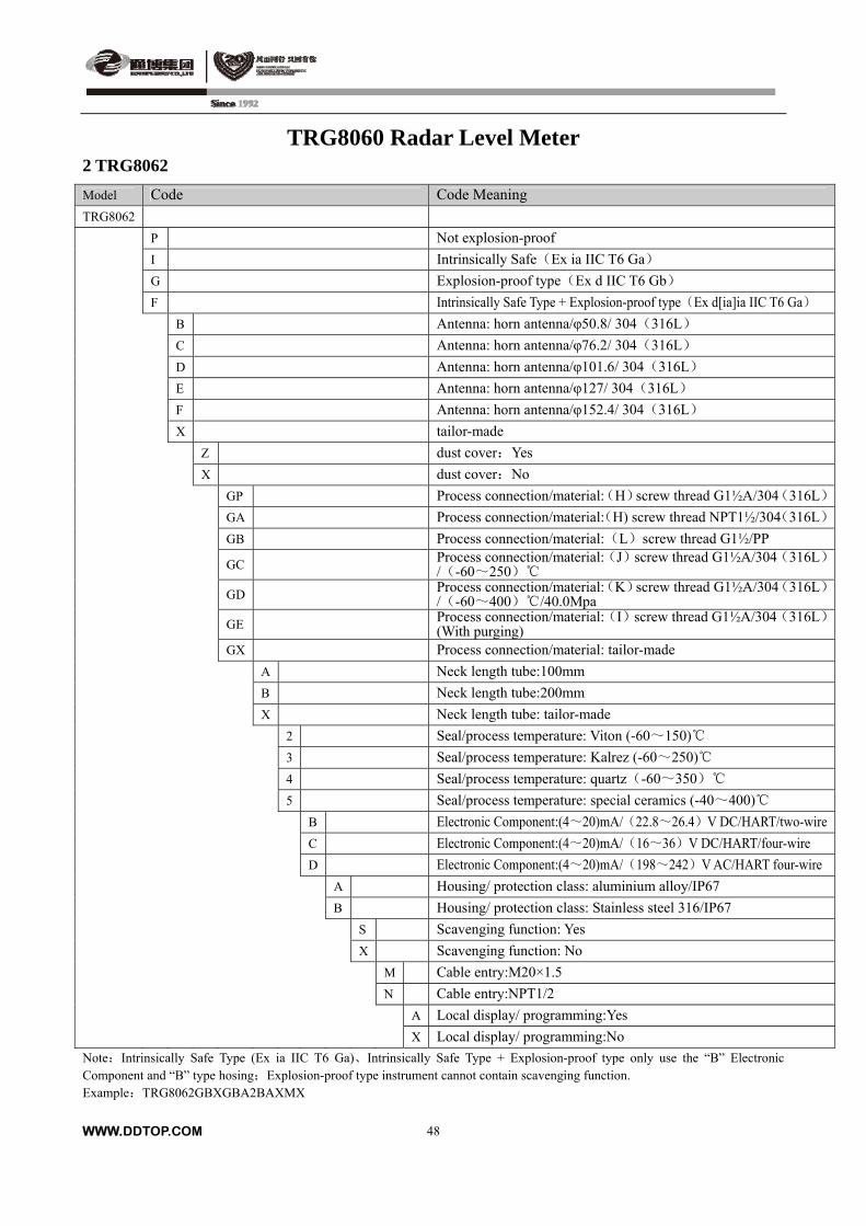
TRG8060 Radar Level Meter 2 TRG8062
Model Code Code Meaning
TRG8062
P Not explosion-proof
I Intrinsically Safe(Ex ia IIC T6 Ga)
G Explosion-proof type(Ex d IIC T6 Gb)
F Intrinsically Safe Type + Explosion-proof type(Ex d[ia]ia IIC T6 Ga)
B Antenna: horn antenna/φ50.8/ 304(316L)
C Antenna: horn antenna/φ76.2/ 304(316L)
D Antenna: horn antenna/φ101.6/ 304(316L)
E Antenna: horn antenna/φ127/ 304(316L)
F Antenna: horn antenna/φ152.4/ 304(316L)
X tailor-made
Z dust cover:Yes
X dust cover:No
GP Process connection/material:(H)screw thread G1½A/304(316L)
GA Process connection/material:(H) screw thread NPT1½/304(316L)
GB Process connection/material:(L)screw thread G1½/PP
GC Process connection/material:(J)screw thread G1½A/304(316L)/(-60~250)
GD Process connection/material:(K)screw thread G1½A/304(316L)/(-60~400)/40.0Mpa
GE Process connection/material:(I)screw thread G1½A/304(316L)(With purging)
GX Process connection/material: tailor-made
A Neck length tube:100mm
B Neck length tube:200mm
X Neck length tube: tailor-made
2 Seal/process temperature: Viton (-60~150)
3 Seal/process temperature: Kalrez (-60~250)
4 Seal/process temperature: quartz(-60~350)
5 Seal/process temperature: special ceramics (-40~400)
B Electronic Component:(4~20)mA/(22.8~26.4)V DC/HART/two-wire
C Electronic Component:(4~20)mA/(16~36)V DC/HART/four-wire
D Electronic Component:(4~20)mA/(198~242)V AC/HART four-wire
A Housing/ protection class: aluminium alloy/IP67
B Housing/ protection class: Stainless steel 316/IP67
S Scavenging function: Yes
X Scavenging function: No
M Cable entry:M20×1.5
N Cable entry:NPT1/2
A Local display/ programming:Yes
X Local display/ programming:No
Note:Intrinsically Safe Type (Ex ia IIC T6 Ga)、Intrinsically Safe Type + Explosion-proof type only use the “B” Electronic Component and “B” type hosing;Explosion-proof type instrument cannot contain scavenging function. Example:TRG8062GBXGBA2BAXMX
WWW.DDTOP.COM
48
WWW.DDTOP.COM
49
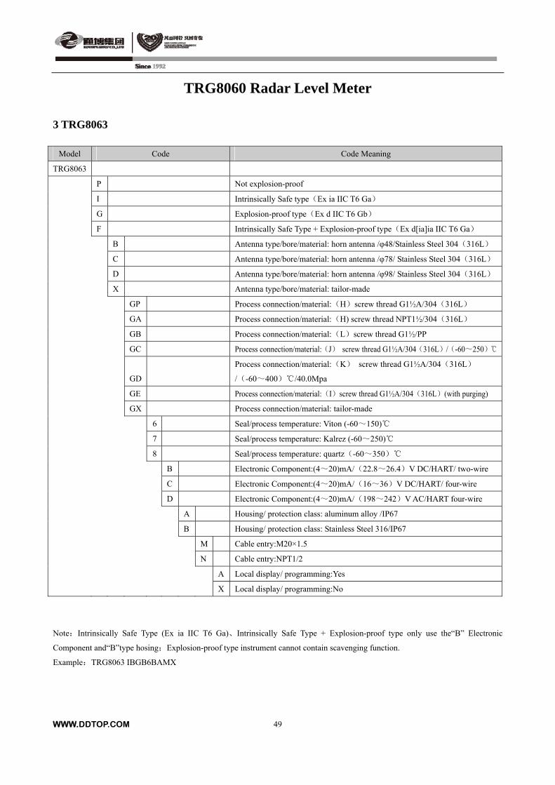
TRG8060 Radar Level Meter 3 TRG8063
Model Code Code Meaning
TRG8063
P Not explosion-proof
I Intrinsically Safe type(Ex ia IIC T6 Ga)
G Explosion-proof type(Ex d IIC T6 Gb)
F Intrinsically Safe Type + Explosion-proof type(Ex d[ia]ia IIC T6 Ga)
B Antenna type/bore/material: horn antenna /φ48/Stainless Steel 304(316L)
C Antenna type/bore/material: horn antenna /φ78/ Stainless Steel 304(316L)
D Antenna type/bore/material: horn antenna /φ98/ Stainless Steel 304(316L)
X Antenna type/bore/material: tailor-made
GP Process connection/material:(H)screw thread G1½A/304(316L)
GA Process connection/material:(H) screw thread NPT1½/304(316L)
GB Process connection/material:(L)screw thread G1½/PP
GC Process connection/material:(J) screw thread G1½A/304(316L)/(-60~250)
GD
Process connection/material:(K) screw thread G1½A/304(316L)
/(-60~400) /40.0Mpa
GE Process connection/material:(I)screw thread G1½A/304(316L)(with purging)
GX Process connection/material: tailor-made
6 Seal/process temperature: Viton (-60~150)
7 Seal/process temperature: Kalrez (-60~250)
8 Seal/process temperature: quartz(-60~350)
B Electronic Component:(4~20)mA/(22.8~26.4)V DC/HART/ two-wire
C Electronic Component:(4~20)mA/(16~36)V DC/HART/ four-wire
D Electronic Component:(4~20)mA/(198~242)V AC/HART four-wire
A Housing/ protection class: aluminum alloy /IP67
B Housing/ protection class: Stainless Steel 316/IP67
M Cable entry:M20×1.5
N Cable entry:NPT1/2
A Local display/ programming:Yes
X Local display/ programming:No
Note:Intrinsically Safe Type (Ex ia IIC T6 Ga)、Intrinsically Safe Type + Explosion-proof type only use the“B” Electronic
Component and“B”type hosing;Explosion-proof type instrument cannot contain scavenging function.
Example:TRG8063 IBGB6BAMX
WWW.DDTOP.COM
50
TRG8060 Radar Level Meter
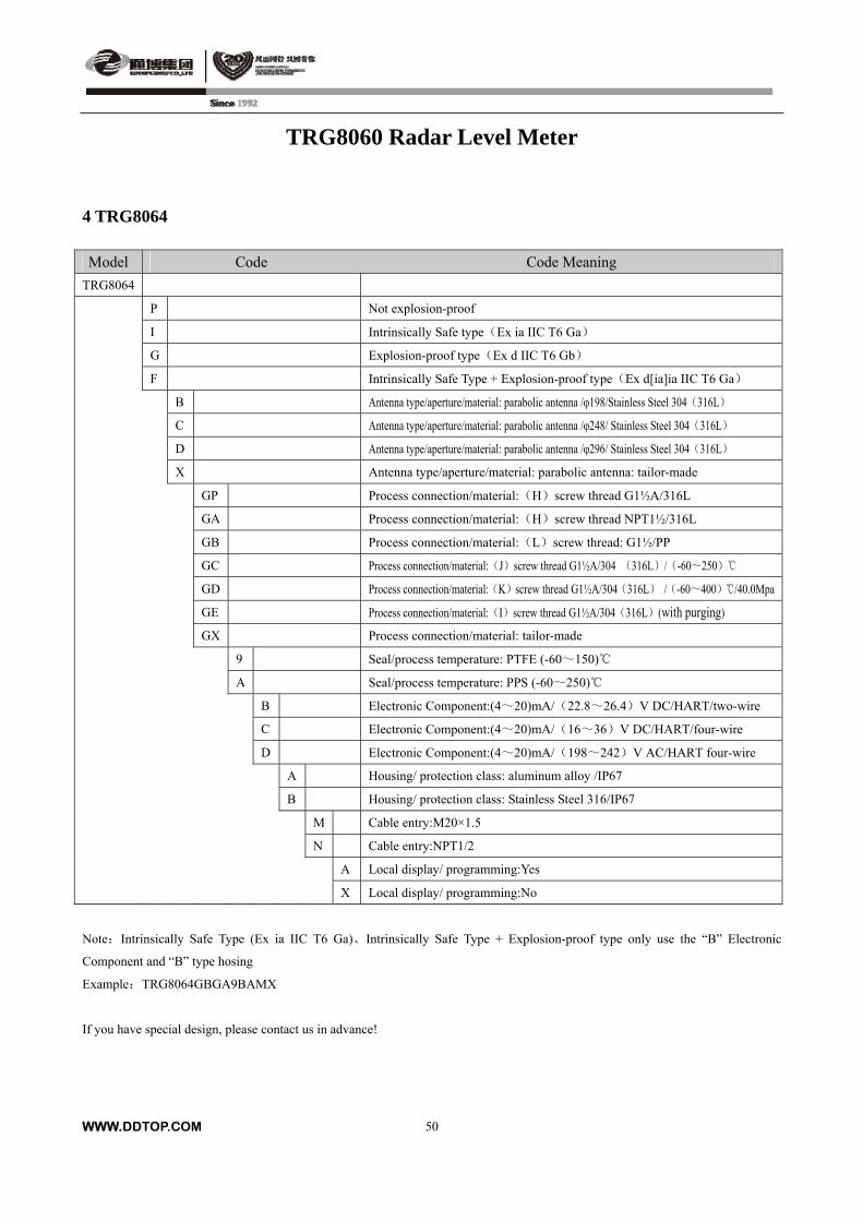
4 TRG8064 Model Code Code Meaning
TRG8064
P Not explosion-proof
I Intrinsically Safe type(Ex ia IIC T6 Ga)
G Explosion-proof type(Ex d IIC T6 Gb)
F Intrinsically Safe Type + Explosion-proof type(Ex d[ia]ia IIC T6 Ga)
B Antenna type/aperture/material: parabolic antenna /φ198/Stainless Steel 304(316L)
C Antenna type/aperture/material: parabolic antenna /φ248/ Stainless Steel 304(316L)
D Antenna type/aperture/material: parabolic antenna /φ296/ Stainless Steel 304(316L)
X Antenna type/aperture/material: parabolic antenna: tailor-made
GP Process connection/material:(H)screw thread G1½A/316L
GA Process connection/material:(H)screw thread NPT1½/316L
GB Process connection/material:(L)screw thread: G1½/PP
GC Process connection/material:(J)screw thread G1½A/304 (316L)/(-60~250)
GD Process connection/material:(K)screw thread G1½A/304(316L) /(-60~400) /40.0Mpa
GE Process connection/material:(I)screw thread G1½A/304(316L)(with purging)
GX Process connection/material: tailor-made
9 Seal/process temperature: PTFE (-60~150)
A Seal/process temperature: PPS (-60~250)
B Electronic Component:(4~20)mA/(22.8~26.4)V DC/HART/two-wire
C Electronic Component:(4~20)mA/(16~36)V DC/HART/four-wire
D Electronic Component:(4~20)mA/(198~242)V AC/HART four-wire
A Housing/ protection class: aluminum alloy /IP67
B Housing/ protection class: Stainless Steel 316/IP67
M Cable entry:M20×1.5
N Cable entry:NPT1/2
A Local display/ programming:Yes
X Local display/ programming:No
Note:Intrinsically Safe Type (Ex ia IIC T6 Ga)、Intrinsically Safe Type + Explosion-proof type only use the “B” Electronic
Component and “B” type hosing
Example:TRG8064GBGA9BAMX
If you have special design, please contact us in advance!
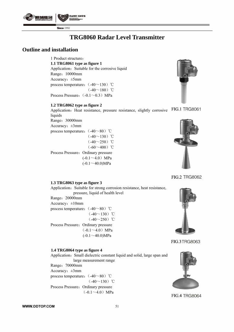
TRG8060 Radar Level Transmitter
Outline and installation
1 Product structure:
WWW.DDTOP.COM
51
1.1 TRG8061 type as figure 1 Application:Suitable for the corrosive liquid Range:10000mm Accuracy:±5mm process temperature:(-40~130)
(-40~180) Process Pressure:(-0.1~0.3)MPa 1.2 TRG8062 type as figure 2 Application:Heat resistance, pressure resistance, slightly corrosive liquids Range:30000mm Accuracy:±3mm process temperature:(-40~80)
(-40~130) (-40~250) (-60~400)
Process Pressure:Ordinary pressure (-0.1~4.0)MPa (-0.1~40.0)MPa
1.3 TRG8063 type as figure 3 Application:Suitable for strong corrosion resistance, heat resistance,
pressure, liquid of health level Range:20000mm Accuracy:±10mm process temperature:(-40~80)
(-40~130) (-40~250)
Process Pressure:Ordinary pressure (-0.1~4.0)MPa
(-0.1~40.0)MPa
1.4 TRG8064 type as figure 4 Application:Small dielectric constant liquid and solid, large span and
large measurement range Range:70000mm Accuracy:±3mm process temperature:(-40~80)
(-40~130) Process Pressure:Ordinary pressure
(-0.1~4.0)MPa

TRG8060 Radar Level Transmitter
2. Parts structure
2.1 head
Number A B
Material Aluminum Alloy Stainless Steel
characteristic Used for Explosion-proof occasions
outside 0 area
Used for zero area(Intrinsically Safe Type
+ Explosion-proof type)
2.2 Process connection
Process connection as below:
Number C D E F H
Material PP Stainless Steel Stainless Steel
(with purging)Stainless Steel Stainless Steel
Pressure Ordinary
pressure (-0.1~4)MPa (-0.1~0.5)MPa (-0.1~4)MPa (-0.1~40)MPa
Temperature (-40~80) (-60~150) (-20~120) (-60~250) (-60~400)
Flange connection accessories table
Number I J K L
Material (PTFE/PP)flange Stainless Steel
Flange
PP Universal joint
flange
Stainless Steel
Universal joint
flange
characteristic corrosion resistance
High
Temperature/High
Pressure
normal temperature
/ordinary pressure
High
Temperature/High
Pressure
WWW.DDTOP.COM
52
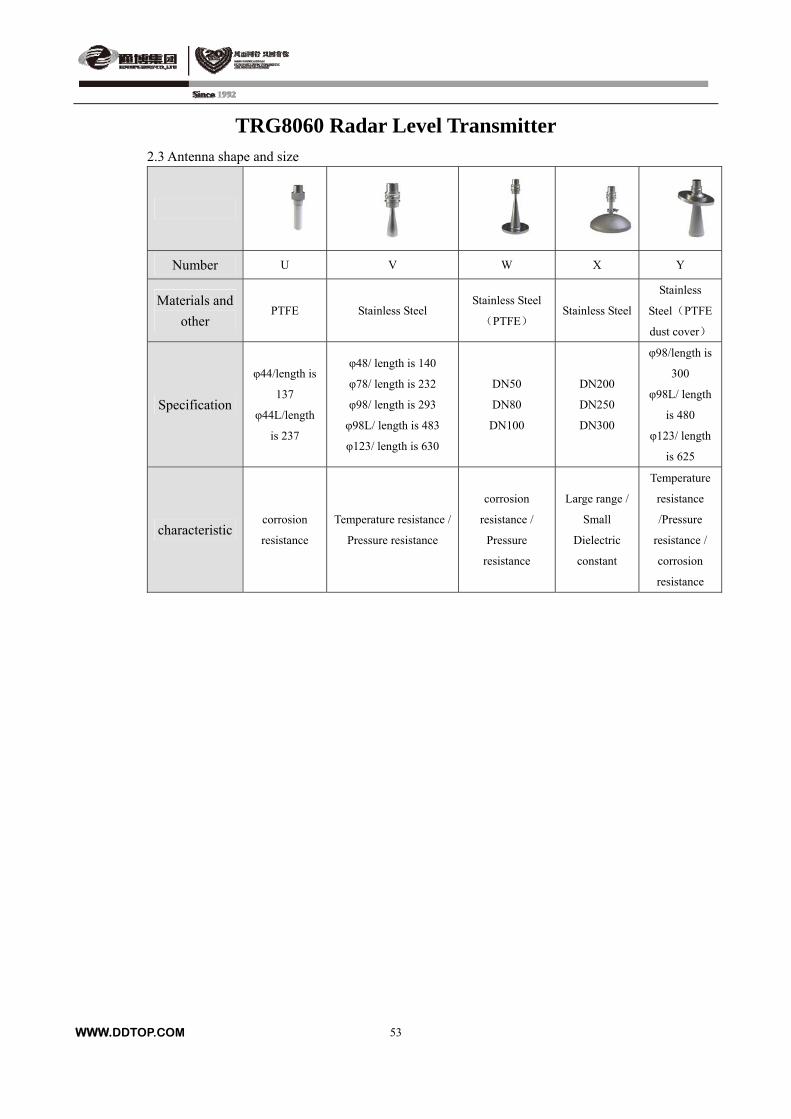
TRG8060 Radar Level Transmitter 2.3 Antenna shape and size
Number U V W X Y
Materials and
other PTFE Stainless Steel
Stainless Steel
(PTFE) Stainless Steel
Stainless
Steel(PTFE
dust cover)
Specification
φ44/length is
137
φ44L/length
is 237
φ48/ length is 140
φ78/ length is 232
φ98/ length is 293
φ98L/ length is 483
φ123/ length is 630
DN50
DN80
DN100
DN200
DN250
DN300
φ98/length is
300
φ98L/ length
is 480
φ123/ length
is 625
characteristic corrosion
resistance
Temperature resistance /
Pressure resistance
corrosion
resistance /
Pressure
resistance
Large range /
Small
Dielectric
constant
Temperature
resistance
/Pressure
resistance /
corrosion
resistance
WWW.DDTOP.COM
53
TRG8060 Radar Level Transmitter
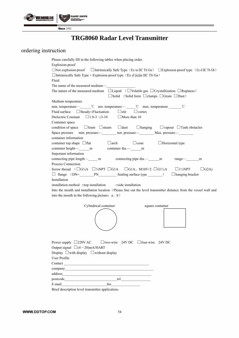
ordering instruction
Please carefully fill in the following tables when placing order.
Explosion-proof
Not explosion-proof Intrinsically Safe Type(Ex ia IIC T6 Ga) Explosion-proof type (Ex d IIC T6 Gb)
Intrinsically Safe Type + Explosion-proof type(Ex d [ia]ia IIC T6 Ga)
Fluid
The name of the measured medium—________________
The nature of the measured medium Liquid (Volatile gas Crystallization Ropiness)
Solid (Solid form clumps Grain Dust)
Medium temperature
min. temperature—______ nor. temperature— _____ max. temperature _______
Fluid surface Steady Fluctuation stir vortex
Dielectric Constant 1.8-3 3-10 More than 10
Container space
condition of space foam steam dust hanging vapour Tank obstacles
Space pressure min. pressure—________ nor. pressure—________ Max. pressure—________
container information
container top shape flat arch cone Horizontal type
container height—______m container dia.—______m
Important information
connecting pipe length—_____ m connecting pipe dia.—______m range—_______m
Process Connection
Screw thread (G¾A ¾NPT G1A G1A、M105×2 G1½A 1½NPT G2A)
flange (DN=________PN__________ Sealing surface type ________) hanging bracket
Installation
installation method top installation side installation
Into the mouth and installation location(Please line out the level transmitter distance from the vessel wall and
into the mouth in the following picture:a、b)
Cylindrical container square container
Power supply 220V AC two-wire 24V DC four-wire 24V DC
Output signal (4~20)mA/HART
Display with display without display
User Profile
Contact _______________________________________________
company_________________________________________________
address_________________________________________________
postcode_____________________________tel.________________
E-mail_________________________fax________________
Brief description level transmitter application:
WWW.DDTOP.COM
54
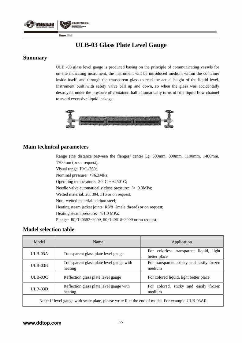
ULB-03 Glass Plate Level Gauge
Summary
ULB -03 glass level gauge is produced basing on the principle of communicating vessels for
on-site indicating instrument, the instrument will be introduced medium within the container
inside itself, and through the transparent glass to read the actual height of the liquid level.
Instrument built with safety valve ball up and down, so when the glass was accidentally
destroyed, under the pressure of container, ball automatically turns off the liquid flow channel
to avoid excessive liquid leakage.
Main technical parameters
Range (the distance between the flanges’ center L): 500mm, 800mm, 1100mm, 1400mm,
1700mm (or on request);
Visual range: H=L-260;
Nominal pressure: ≤6.3MPa;
Operating temperature: -20。C ~ +250。C;
Needle valve automatically close pressure: ≥ 0.3MPa;
Wetted material: 20, 304, 316 or on request;
Non- wetted material: carbon steel;
Heating steam jacket joints: R3/8 (male thread) or on request; Heating steam pressure: ≤1.0 MPa;
Flange: HG/T20592-2009, HG/T20615-2009 or on request;
Model selection table
Model Name Application
ULB-03A Transparent glass plate level gauge For colorless transparent liquid, light better place
ULB-03B Transparent glass plate level gauge with heating
For transparent, sticky and easily frozen medium
ULB-03C Reflection glass plate level gauge For colored liquid, light better place
ULB-03D Reflection glass plate level gauge with heating
For colored, sticky and easily frozen medium
Note: If level gauge with scale plate, please write R at the end of model. For example:ULB-03AR
www.ddtop.com 55
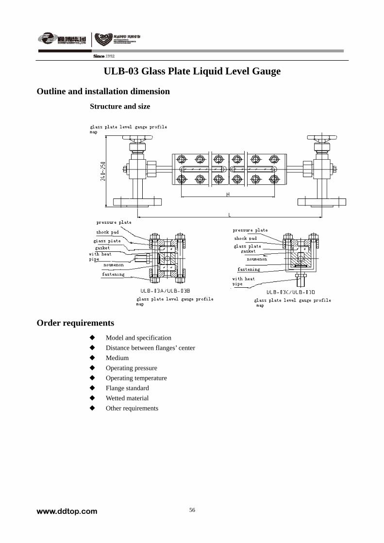
ULB-03 Glass Plate Liquid Level Gauge
Outline and installation dimension
Structure and size
Order requirements
Model and specification
Distance between flanges’ center
Medium
Operating pressure
Operating temperature
Flange standard
Wetted material
Other requirements
www.ddtop.com 56
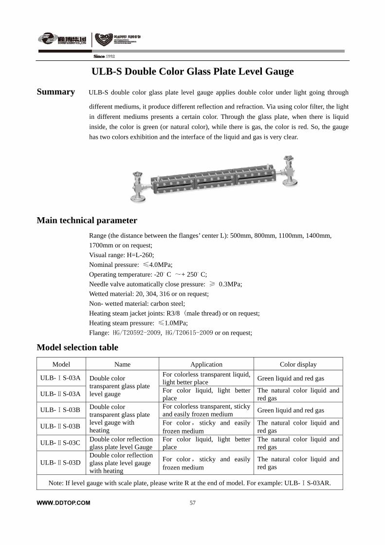
ULB-S Double Color Glass Plate Level Gauge
Summary ULB-S double color glass plate level gauge applies double color under light going through
different mediums, it produce different reflection and refraction. Via using color filter, the light
in different mediums presents a certain color. Through the glass plate, when there is liquid
inside, the color is green (or natural color), while there is gas, the color is red. So, the gauge
has two colors exhibition and the interface of the liquid and gas is very clear.
Main technical parameter
Range (the distance between the flanges’ center L): 500mm, 800mm, 1100mm, 1400mm,
1700mm or on request;
Visual range: H=L-260;
Nominal pressure: ≤4.0MPa;
Operating temperature: -20。C ~+ 250。C;
Needle valve automatically close pressure: ≥ 0.3MPa;
Wetted material: 20, 304, 316 or on request;
Non- wetted material: carbon steel;
Heating steam jacket joints: R3/8 (male thread) or on request; Heating steam pressure: ≤1.0MPa;
Flange: HG/T20592-2009, HG/T20615-2009 or on request;
Model selection table
Model Name Application Color display
ULB-ⅠS-03A For colorless transparent liquid, light better place
Green liquid and red gas
ULB-ⅡS-03A
Double color transparent glass plate level gauge For color liquid, light better
place The natural color liquid and red gas
ULB-ⅠS-03B For colorless transparent, sticky and easily frozen medium
Green liquid and red gas
ULB-ⅡS-03B
Double color transparent glass plate level gauge with heating
For color, sticky and easily frozen medium
The natural color liquid and red gas
ULB-ⅡS-03C Double color reflection glass plate level Gauge
For color liquid, light better place
The natural color liquid and red gas
ULB-ⅡS-03D Double color reflection glass plate level gauge with heating
For color, sticky and easily frozen medium
The natural color liquid and red gas
Note: If level gauge with scale plate, please write R at the end of model. For example: ULB-ⅠS-03AR.
WWW.DDTOP.COM
57
ULB-S Double Color Glass Plate Liquid Level Gauge
Outline and installation dimensions
Structure and size
Order requirements
Model and specification
Distance between flanges’ center
Medium
Operating pressure
Operating temperature
Flange standard
Wetted material
Other requirements
WWW.DDTOP.COM
58
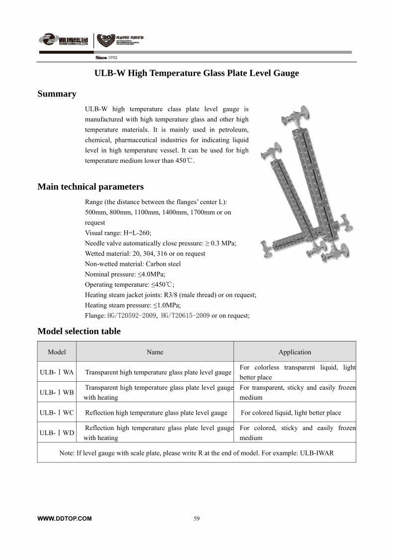
ULB-W High Temperature Glass Plate Level Gauge
Summary
ULB-W high temperature class plate level gauge is
manufactured with high temperature glass and other high
temperature materials. It is mainly used in petroleum,
chemical, pharmaceutical industries for indicating liquid
level in high temperature vessel. It can be used for high
temperature medium lower than 450 .
Main technical parameters
Range (the distance between the flanges’ center L):
500mm, 800mm, 1100mm, 1400mm, 1700mm or on
request
Visual range: H=L-260;
Needle valve automatically close pressure: ≥ 0.3 MPa;
Wetted material: 20, 304, 316 or on request
Non-wetted material: Carbon steel
Nominal pressure: ≤4.0MPa;
Operating temperature: ≤450;
Heating steam jacket joints: R3/8 (male thread) or on request;
Heating steam pressure: ≤1.0MPa;
Flange: HG/T20592-2009, HG/T20615-2009 or on request;
Model selection table
Model Name Application
ULB- WAⅠ Transparent high temperature glass plate level gaugeFor colorless transparent liquid, light
better place
ULB- WBⅠ Transparent high temperature glass plate level gauge
with heating
For transparent, sticky and easily frozen
medium
ULB- WCⅠ Reflection high temperature glass plate level gauge For colored liquid, light better place
ULB- WDⅠ Reflection high temperature glass plate level gauge
with heating
For colored, sticky and easily frozen
medium
Note: If level gauge with scale plate, please write R at the end of model. For example: ULB-IWAR
WWW.DDTOP.COM
59
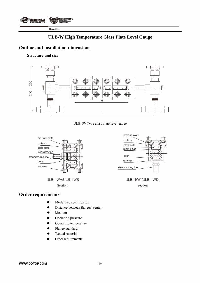
ULB-W High Temperature Glass Plate Level Gauge
Outline and installation dimensions
Structure and size
ULB-IW Type glass plate level gauge
Order requirements
Model and specification
Distance between flanges’ center
Medium
Operating pressure
Operating temperature
Flange standard
Wetted material
Other requirements
WWW.DDTOP.COM
60

ULB- WY High Temperature & High Pressure
Glass Plate Level Gauge
Summary
ULB- WY series glass plate level gauge is made from high pressure & temperature glass and high
strength material through special technical treatment, being applied for level indication in high
pressure & high temperature vessels in petroleum and chemical industries, etc.
Main technical parameters
Range (the distance between the flanges’ center L): 500mm, 800mm, 1100mm, 1400mm or on
request;
Visual range: H=L-260;
Nominal pressure: ≤26.0MPa;
Operating temperature: ≤500;
Needle valve automatically close pressure: ≥ 0.3 MPa;
Wetted material: 20, 304, 316 or on request
Non-wetted material: Carbon steel
Heating steam jacket joints: R3/8 (male thread) or on request;
Heating steam pressure: ≤1.0MPa;
Flange: HG/T20592-2009, HG/T20615-2009 or on request;
Model selection table
Model Name Application
ULB-WYA High temperature & pressure glass plate level gauge
For colorless transparent liquid, light better place
ULB-WYB High temperature & pressure glass plate level gauge with heating
Sticky and easily frozen medium
WWW.DDTOP.COM
61
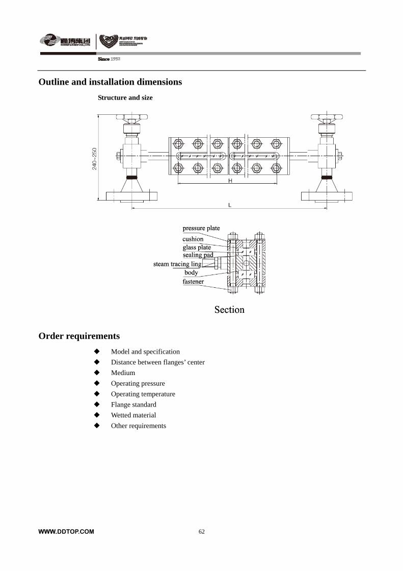
Outline and installation dimensions
Structure and size
Order requirements
Model and specification
Distance between flanges’ center
Medium
Operating pressure
Operating temperature
Flange standard
Wetted material
Other requirements
WWW.DDTOP.COM
62
ULB-T Cylindrical Body Glass Plate Level Gauge
Summary
ULB-T cylindrical body glass plate level gauge is equipped with cylindrical tube as its body, big
bore diameter, so it is applied large indicating range and sticky medium application.
Main technical parameters
Range (the distance between the flanges’ center L): 500 ~6500mm;
Visual range: H>L-200;
Nominal pressure: ≤4.0MPa;
Operating temperature: -20 ~ +250;
Wetted material: 20, 304, 316 or on request;
Non-wetted material: Carbon steel
Flange: HG/T20592-2009, HG/T20615-2009 or on request;
Model selection table
Model Contents Application
ULB-TT Cylindrical body transparent typeFor colorless transparent liquid, light better
place
ULB-TR Cylindrical body reflection type For colored liquid, light better place
WWW.DDTOP.COM
63
Outline and installation dimensions
Structure and size
Order requirements
Model and specification
Distance between flanges’ center
Medium
Operating pressure
Operating temperature
Flange standard
Wetted material
Other requirements
WWW.DDTOP.COM
64
ULB-M No Blind Zone Glass Plate Level Gauge
Summary
The glass plates are staggered on both view sides of ULB-M no
blind zone glass plate level gauge. Level can be continuous
observed, both upper and lower flanges connecting to vessel are
within visual range.
Main technical parameters
Range (the distance between the flanges’ center L): 500mm,
800mm, 1100mm, 1400mm, 1700mm;
Visual range: H≥L;
Nominal pressure: ≤4.0MPa;
Operating temperature: -20 ~ +250;
Wetted material: 20, 304, 316 or on request
Non-wetted material: Carbon steel
Heating steam jacket joints: R3/8 (male thread) or on request;
Heating steam pressure: ≤1MPa;
Flange: HG/T20592-2009, HG/T20615-2009 or on request;
Model selection table
Model Name Application
ULB-MA Flange without valve type
ULB-MB Flange with valve model
For colorless transparent liquid, light
better place
ULB-MAE Flange without valve type with heating
ULB-MBE Flange with valve type with heating Sticky and easily frozen medium
WWW.DDTOP.COM
65
ULB-M No Blind Zone Glass Plate Level Gauge
Outline and installation dimensions
Structure and size
Order requirements
Model and specification
Distance between flanges’ center
Medium
Operating pressure
Operating temperature
Flange standard
Wetted material
Other requirements
WWW.DDTOP.COM
66
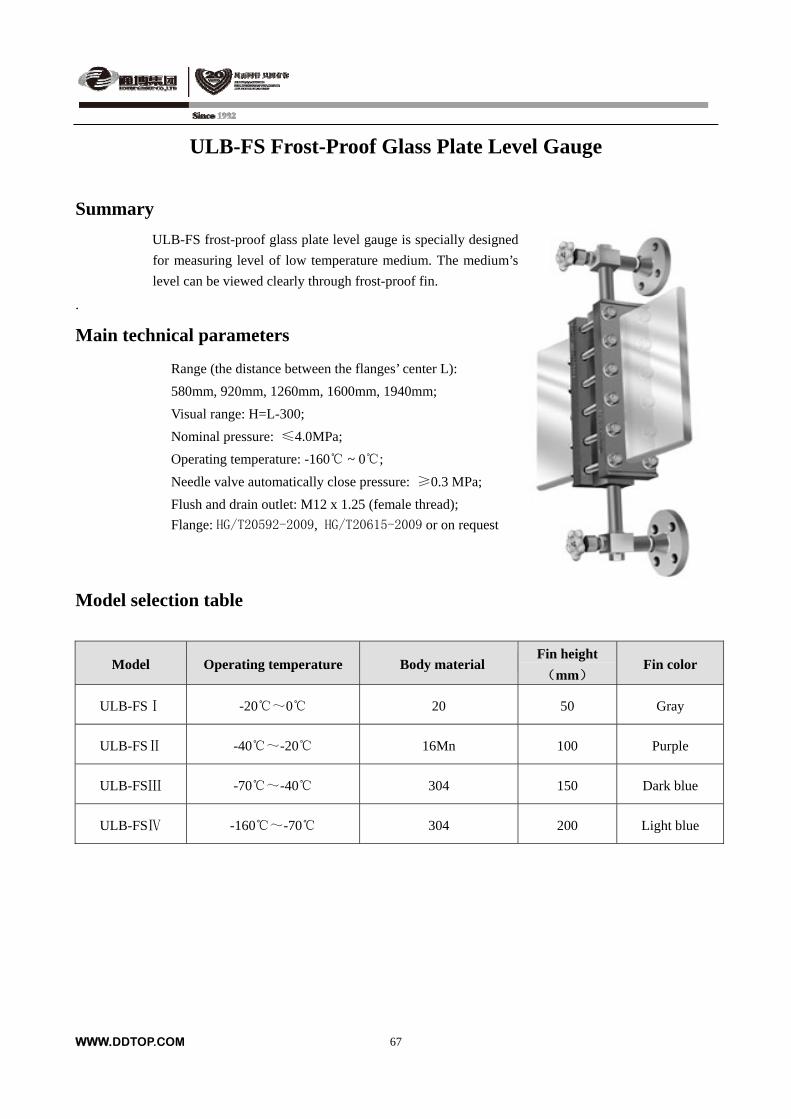
ULB-FS Frost-Proof Glass Plate Level Gauge
Summary
ULB-FS frost-proof glass plate level gauge is specially designed
for measuring level of low temperature medium. The medium’s
level can be viewed clearly through frost-proof fin.
.
Main technical parameters
Range (the distance between the flanges’ center L):
580mm, 920mm, 1260mm, 1600mm, 1940mm;
Visual range: H=L-300;
Nominal pressure: ≤4.0MPa;
Operating temperature: -160 ~ 0;
Needle valve automatically close pressure: ≥0.3 MPa;
Flush and drain outlet: M12 x 1.25 (female thread);
Flange: HG/T20592-2009, HG/T20615-2009 or on request
Model selection table
Model Operating temperature Body material Fin height
(mm) Fin color
ULB-FSⅠ -20~0 20 50 Gray
ULB-FSⅡ -40~-20 16Mn 100 Purple
ULB-FSⅢ -70~-40 304 150 Dark blue
ULB-FSⅣ -160~-70 304 200 Light blue
WWW.DDTOP.COM
67
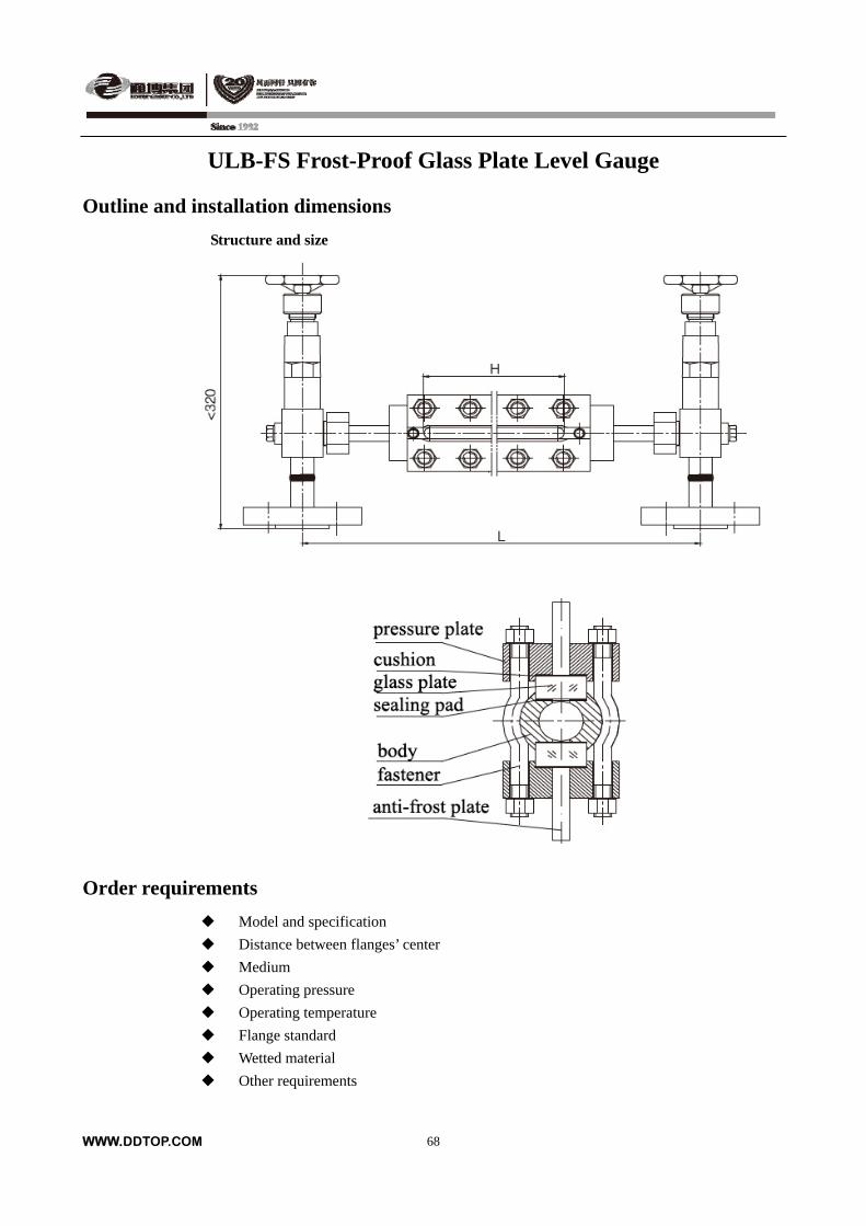
ULB-FS Frost-Proof Glass Plate Level Gauge
Outline and installation dimensions
Structure and size
Order requirements
Model and specification
Distance between flanges’ center
Medium
Operating pressure
Operating temperature
Flange standard
Wetted material
Other requirements
WWW.DDTOP.COM
68
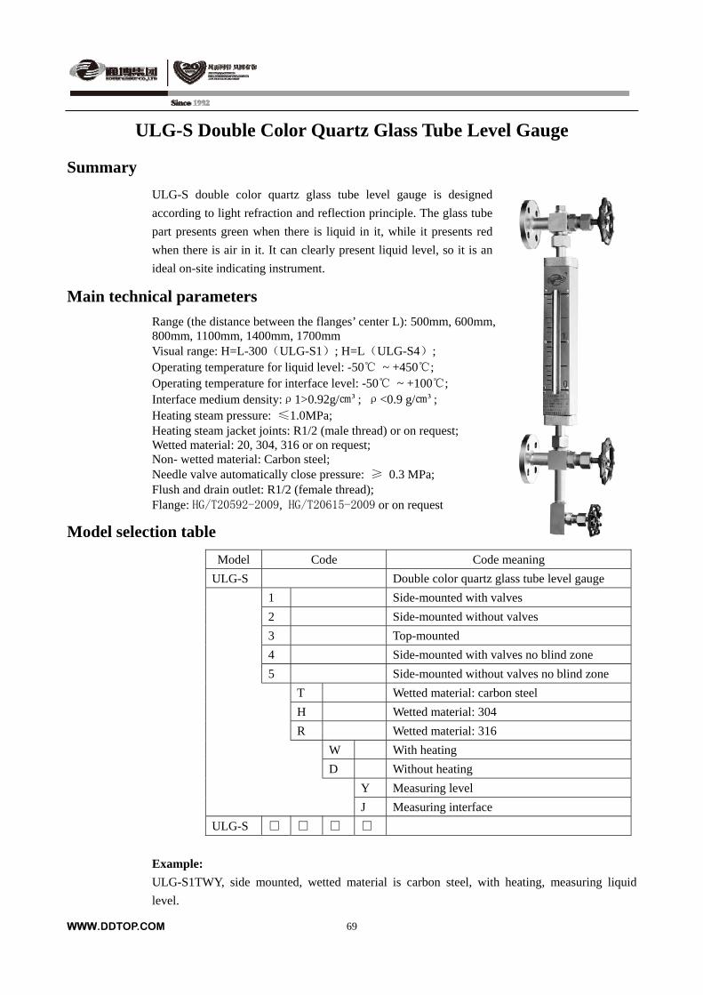
ULG-S Double Color Quartz Glass Tube Level Gauge
Summary
ULG-S double color quartz glass tube level gauge is designed
according to light refraction and reflection principle. The glass tube
part presents green when there is liquid in it, while it presents red
when there is air in it. It can clearly present liquid level, so it is an
ideal on-site indicating instrument.
Main technical parameters
Range (the distance between the flanges’ center L): 500mm, 600mm, 800mm, 1100mm, 1400mm, 1700mm Visual range: H=L-300(ULG-S1); H=L(ULG-S4); Operating temperature for liquid level: -50 ~ +450; Operating temperature for interface level: -50 ~ +100; Interface medium density:ρ1>0.92g/³; ρ<0.9 g/³; Heating steam pressure: ≤1.0MPa; Heating steam jacket joints: R1/2 (male thread) or on request; Wetted material: 20, 304, 316 or on request; Non- wetted material: Carbon steel; Needle valve automatically close pressure: ≥ 0.3 MPa; Flush and drain outlet: R1/2 (female thread); Flange: HG/T20592-2009, HG/T20615-2009 or on request
Model selection table
Model Code Code meaning
ULG-S Double color quartz glass tube level gauge
1 Side-mounted with valves
2 Side-mounted without valves
3 Top-mounted
4 Side-mounted with valves no blind zone
5 Side-mounted without valves no blind zone
T Wetted material: carbon steel
H Wetted material: 304
R Wetted material: 316
W With heating
D Without heating
Y Measuring level
J Measuring interface
ULG-S
Example:
ULG-S1TWY, side mounted, wetted material is carbon steel, with heating, measuring liquid
level.
WWW.DDTOP.COM
69
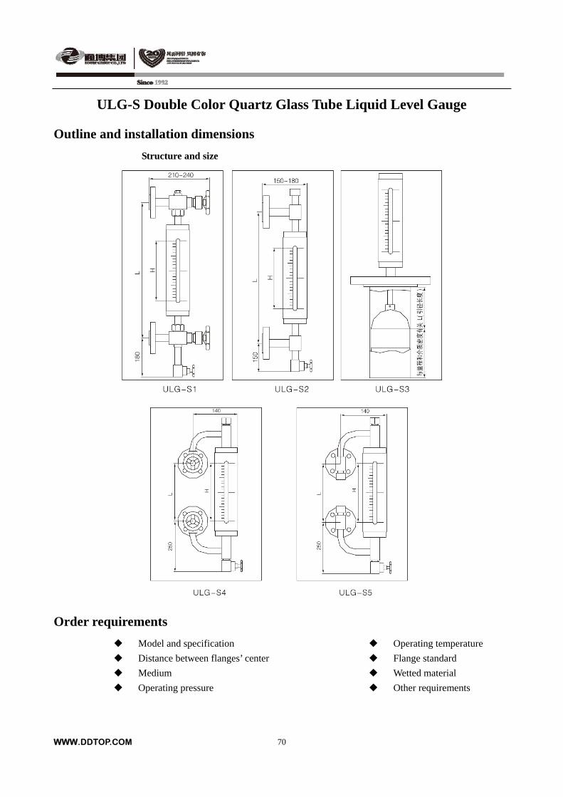
ULG-S Double Color Quartz Glass Tube Liquid Level Gauge
Outline and installation dimensions
Structure and size
Order requirements
Model and specification Operating temperature
Distance between flanges’ center Flange standard
Medium Wetted material
Operating pressure Other requirements
WWW.DDTOP.COM
70
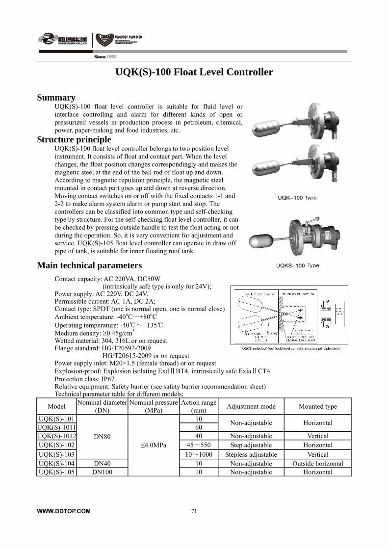
UQK(S)-100 Float Level Controller
Summary UQK(S)-100 float level controller is suitable for fluid level or interface controlling and alarm for different kinds of open or pressurized vessels in production process in petroleum, chemical, power, paper-making and food industries, etc.
Structure principle UQK(S)-100 float level controller belongs to two position level instrument. It consists of float and contact part. When the level changes, the float position changes correspondingly and makes the magnetic steel at the end of the ball rod of float up and down. According to magnetic repulsion principle, the magnetic steel mounted in contact part goes up and down at reverse direction. Moving contact switches on or off with the fixed contacts 1-1 and 2-2 to make alarm system alarm or pump start and stop. The controllers can be classified into common type and self-checking type by structure. For the self-checking float level controller, it can be checked by pressing outside handle to test the float acting or not during the operation. So, it is very convenient for adjustment and service. UQK(S)-105 float level controller can operate in draw off pipe of tank, is suitable for inner floating roof tank.
Main technical parameters
Contact capacity: AC 220VA, DC50W (intrinsically safe type is only for 24V); Power supply: AC 220V, DC 24V; Permissible current: AC 1A, DC 2A; Contact type: SPDT (one is normal open, one is normal close) Ambient temperature: -40oC~+80oC Operating temperature: -40~+135 Medium density: ≥0.45g/cm3 Wetted material: 304, 316L or on request Flange standard: HG/T20592-2009
HG/T20615-2009 or on request Power supply inlet: M20×1.5 (female thread) or on request Explosion-proof: Explosion isolating ExdⅡBT4, intrinsically safe ExiaⅡCT4 Protection class: IP67 Relative equipment: Safety barrier (see safety barrier recommendation sheet) Technical parameter table for different models:
Model Nominal diameter
(DN) Nominal pressure
(MPa) Action range
(mm) Adjustment mode Mounted type
UQK(S)-101 10 UQK(S)-1011 60
Non-adjustable Horizontal
UQK(S)-1012 40 Non-adjustable Vertical UQK(S)-102 45~550 Step adjustable Horizontal
UQK(S)-103
DN80
10~1000 Stepless adjustable Vertical UQK(S)-104 DN40 10 Non-adjustable Outside horizontal UQK(S)-105 DN100
≤4.0MPa
10 Non-adjustable Horizontal
WWW.DDTOP.COM
71
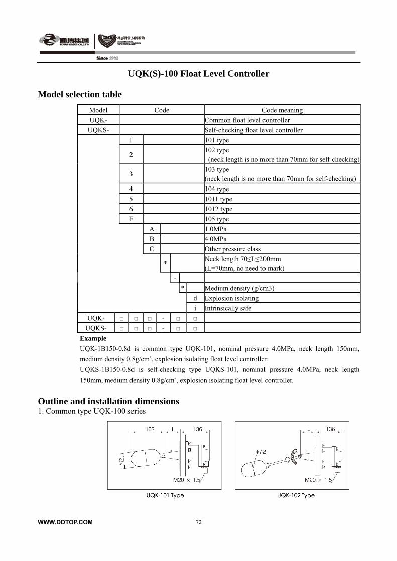
UQK(S)-100 Float Level Controller
Model selection table
Model Code Code meaning
UQK- Common float level controller
UQKS- Self-checking float level controller
1 101 type
2 102 type (neck length is no more than 70mm for self-checking)
3 103 type (neck length is no more than 70mm for self-checking)
4 104 type
5 1011 type
6 1012 type
F 105 type
A 1.0MPa
B 4.0MPa
C Other pressure class
* Neck length 70≤L≤200mm (L=70mm, no need to mark)
-
* Medium density (g/cm3)
d Explosion isolating
i Intrinsically safe
UQK- -
UQKS- -
Example
UQK-1B150-0.8d is common type UQK-101, nominal pressure 4.0MPa, neck length 150mm,
medium density 0.8g/cm³, explosion isolating float level controller.
UQKS-1B150-0.8d is self-checking type UQKS-101, nominal pressure 4.0MPa, neck length
150mm, medium density 0.8g/cm³, explosion isolating float level controller.
Outline and installation dimensions 1. Common type UQK-100 series
WWW.DDTOP.COM
72
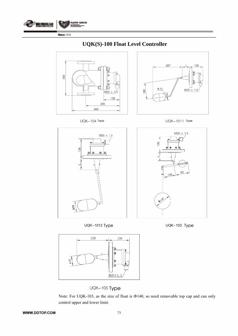
UQK(S)-100 Float Level Controller
Note: For UQK-103, as the size of float is Ф140, so need removable top cap and can only
control upper and lower limit.
WWW.DDTOP.COM
73
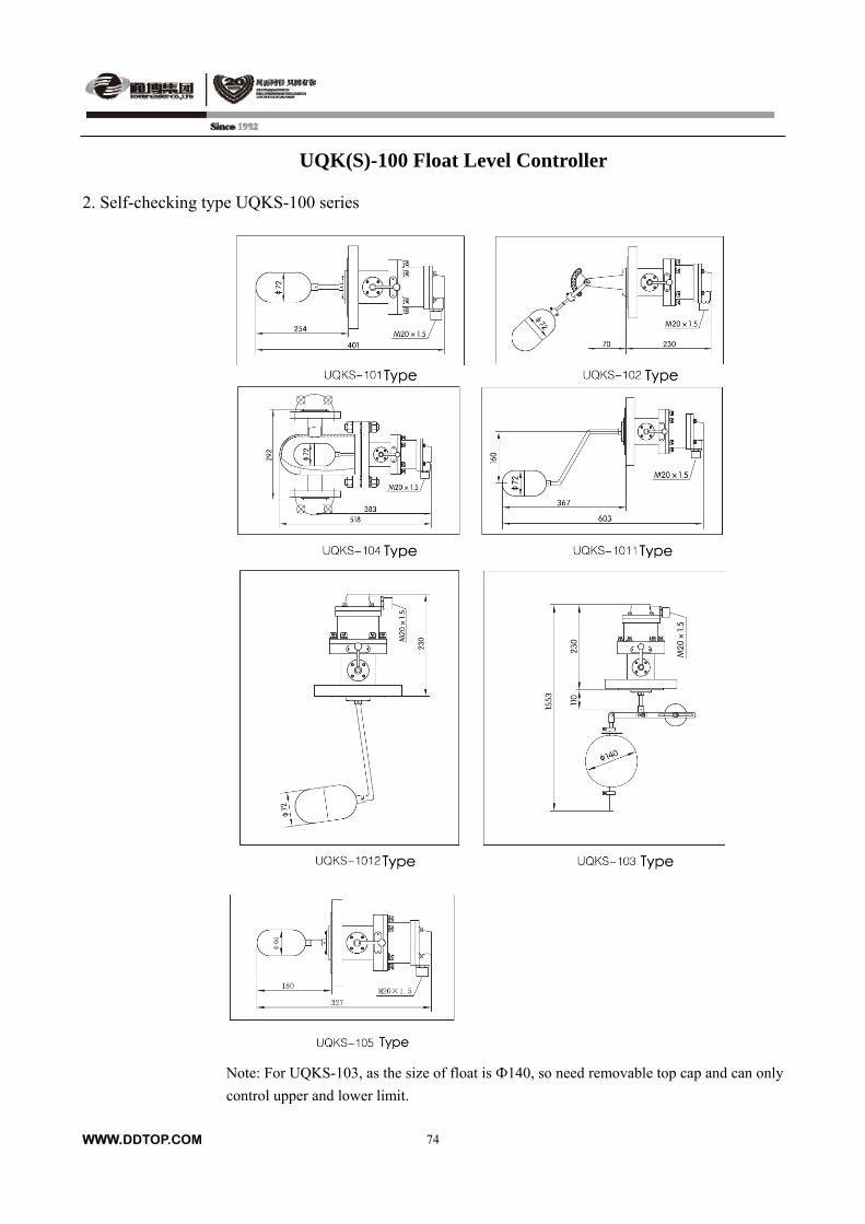
UQK(S)-100 Float Level Controller
2. Self-checking type UQKS-100 series
Note: For UQKS-103, as the size of float is Ф140, so need removable top cap and can only
control upper and lower limit.
WWW.DDTOP.COM
74
UQK(S)-100 Float Level Controller
3. Installation schematic plan
Safety barrier recommendation sheet
Dandong Top Electronics Instrument Co., Ltd TP5041-Ex, TP5045-Ex
Shanghai Automation Instrument Institute CS8041-Ex, CS8045-Ex
Order requirements
Type specification Mounted type Operating medium Operating pressure Operating temperature Flange standard Wetted material Medium density Neck length Other special requirement
WWW.DDTOP.COM
75
UQK-300 Float Level Controller
Summary
UQK-300 float level controller is suitable for level or interface
controlling and alarm for different kinds of vessels in production
process in petroleum, chemical, textile dyeing and finishing, and
water treatment, etc.
Operating principle
UQK-300 float level controller consists of magnetic float, isolating
tube, reed switch, junction box, etc. Magnetic float moves up and
down with the level change and reed switch operates at setting alarm
position to control the alarm system alarming or the pump to start and
stop.
Main technical parameter
Control length: 0~6000 mm
Basic error: ±10mm
Contact type: one is normal open, one is normal close
Contact capacity: AC 100VA, DC100VA
(intrinsically safe type is only for 24V)
Max.voltage: 250V
Max. current: 1A
Nominal pressure: ≤2.5MPa
Nominal diameter: DN150, DN100
Ambient temperature: -40~+80
Operating temperature: -20~+120
Medium density: for level: ρ≥0.65g/cm3
for interface: ρ1-ρ2≥0.25g/cm3
Wetted material: 304, 306L or on request
Flange standard: HG/T20592-2009, HG/T20615-2009
or on request
Power supply inlet: M20×1.5(female thread)
or on request
Protection class: IP67
Relative equipment: safety barrier (see safety barrier
recommendation sheet)
Outline and structure sketch of
UQK-300 float level controller
WWW.DDTOP.COM
76
WWW.DDTOP.COM
77
UQK-300 Float Level Controller
Model selection table
Model Code Code meaning
UQK- Float level controller
300 Top-mounted
L1 Upper limit alarm
L2 Lower limit alarm
Y Upper, lower limit alarm
-
* Distance from upper alarm setting position to flange interface
-
* Distance from lower alarm setting position to flange interface
-
* Medium density(g/cm³)
d Explosion isolating
i Intrinsically safe
Example
UQK-300Y-300-1500-0.8d is top mounted, upper, lower limit alarm, distance from upper
alarm setting position to flange interface is 300mm, distance from lower alarm setting position
to flange interface is 1500mm, medium density is 0.8(g/cm³) and intrinsically safe
explosion-proof float level controller.
Outline and installation dimensions
1. Outline and structure sketch of UQK-300 float level controller as above. 2. Safety barrier recommendation sheet
Dandong Top Electronics Instrument Co., Ltd TP5041-Ex, TP5045-Ex
Shanghai Automation Instrument Institute CS8041-Ex, CS8045-Ex
Order requirements
Type specification
Operating medium
Operating pressure
Operating temperature
Flange standard
Wetted material
Medium density
The number and position of alarm
Other special requirement
UQK-400 Float Level Controller
Summary
UQK-400 float level controller consists of float, connecting rod, iron core unit and magnetic
switches / signal conversion device. The float movess up and down with level changes in the vessel
and makes connecting rod and iron core unit move up and down. This makes the position of the
magnetic steel in the iron core change, through the magnetic coupling effect to make microswitch
or reed switch acting. It will realize the functions of level controlling and alarming.
Main technical parameter
Range: 60mm ~120mm
Measuring accuracy: level controlling: ±4mm;
interface controlling: ±6mm;
Nominal pressure: ≤6.3Mpa
Wetted material: 304, 316L or on request
Nominal diameter: DN80
Flange standard: HG/T20592-2009,
HG/T20615-2009 or on request
Ambient temperature: -40 ~ +80
Operating temperature: -40 ~ +150
Service life: ≥5×10⁵
Medium density: For level controlling: ρ ≥ 0.6g/cm3;
For interface controlling: ρ1 - ρ2 ≥ 0.16g/cm3
Medium viscosity: ≤ 1St (10-4m2/s)
Power supply inlet: G1/2″ (female thread) or on request
Explosion-proof: ExdⅡCT4, ExiaⅡCT4
Protection class: IP67
Relative equipment: safety barrier (see safety barrier recommendation sheet)
Contact capacity:
Switch type Max.
Voltage AC
Max.
Current (A)
Contact point
number
Contact
Resistance
( Ω)≯
Switching speed
( ms)≯
Service life
( 10≮ 4 times)
Reed switch 250 V 1 SPDT 0.03 3 50
Microswitch 250 V 5 SPDT 0.03 3 50
Note: 24V DC is only for intrinsically safe.
WWW.DDTOP.COM
78
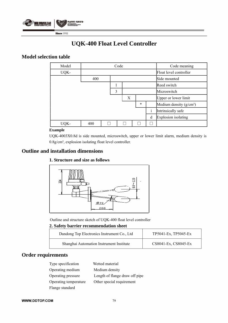
UQK-400 Float Level Controller
Model selection table
Model Code Code meaning
UQK- Float level controller
400 Side mounted
1 Reed switch
3 Microswitch
X Upper or lower limit
* Medium density (g/cm³)
i Intrinsically safe
d Explosion isolating
UQK- 400
Example
UQK-4003X0.8d is side mounted, microswitch, upper or lower limit alarm, medium density is
0.8g/cm³, explosion isolating float level controller.
Outline and installation dimensions
1. Structure and size as follows
Outline and structure sketch of UQK-400 float level controller
2. Safety barrier recommendation sheet
Dandong Top Electronics Instrument Co., Ltd TP5041-Ex, TP5045-Ex
Shanghai Automation Instrument Institute CS8041-Ex, CS8045-Ex
Order requirements
Type specification Wetted material
Operating medium Medium density
Operating pressure Length of flange draw off pipe
Operating temperature Other special requirement
Flange standard
WWW.DDTOP.COM
79
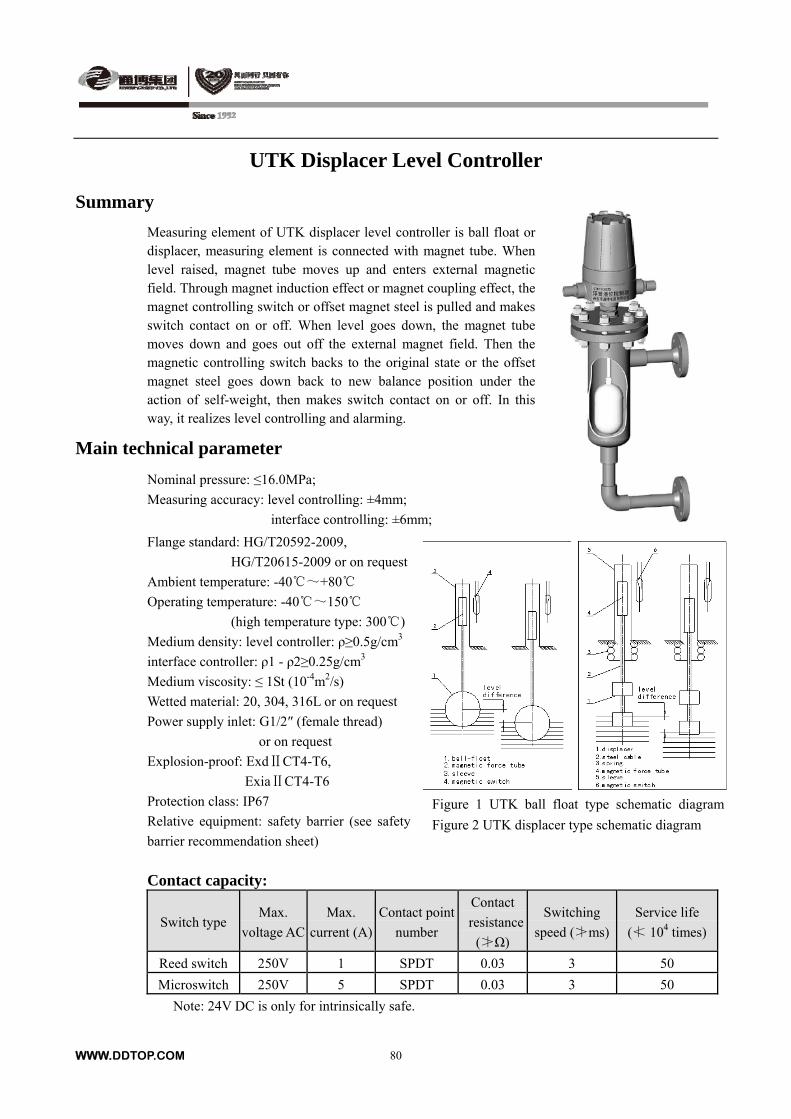
UTK Displacer Level Controller
Summary
Measuring element of UTK displacer level controller is ball float or displacer, measuring element is connected with magnet tube. When level raised, magnet tube moves up and enters external magnetic field. Through magnet induction effect or magnet coupling effect, the magnet controlling switch or offset magnet steel is pulled and makes switch contact on or off. When level goes down, the magnet tube moves down and goes out off the external magnet field. Then the magnetic controlling switch backs to the original state or the offset magnet steel goes down back to new balance position under the action of self-weight, then makes switch contact on or off. In this way, it realizes level controlling and alarming.
Main technical parameter
Nominal pressure: ≤16.0MPa;
Measuring accuracy: level controlling: ±4mm;
interface controlling: ±6mm;
Flange standard: HG/T20592-2009,
HG/T20615-2009 or on request
Ambient temperature: -40~+80
Operating temperature: -40~150
(high temperature type: 300)
Medium density: level controller: ρ≥0.5g/cm3
interface controller: ρ1 - ρ2≥0.25g/cm3
Medium viscosity: ≤ 1St (10-4m2/s)
Wetted material: 20, 304, 316L or on request
Power supply inlet: G1/2″ (female thread)
or on request
Explosion-proof: ExdⅡCT4-T6,
ExiaⅡCT4-T6
Protection class: IP67 Figure 1 UTK ball float type schematic diagram
Figure 2 UTK displacer type schematic diagram Relative equipment: safety barrier (see safety
barrier recommendation sheet)
Contact capacity:
Switch type Max.
voltage AC
Max.
current (A)
Contact point
number
Contact
resistance
( Ω)≯
Switching
speed ( ms)≯
Service life
( 10≮ 4 times)
Reed switch 250V 1 SPDT 0.03 3 50
Microswitch 250V 5 SPDT 0.03 3 50
Note: 24V DC is only for intrinsically safe.
WWW.DDTOP.COM 80

WWW.DDTOP.COM 81
UTK Displacer Level Controller
Controlling range: For level controlling
Model Measuring
element
Controlling
position
Max.pressure
MPa
Nominal
diameter
Alarming
setting-point
B (mm)
Range
H (mm) Remark
UTK100 Ball float
Upper
Or lower
limit
6.3 DN40 On request
Controlling
position
non-adjustable
Upper
Or lower
limit
UTK300 Displacer Upper and
lower
limits
4.0 DN80 On request
On request
Controlling
position is
adjustable;
The rang of
upper limit
and
low limit are
adjustable.
UTK400 Displacer
Upper
Or lower
limit
16.0 DN40 On request
Controlling
position
non-adjustable
For interface controlling:
Min.density Min.density difference
Model Controlling
position Max.pressure
MPa g/cm3
Alarming setting-point B (mm)
Ball-float Upper or
lower limit 4.0 0.5 0.25 On request
WWW.DDTOP.COM 82
UTK Displacer Level Controller
Model selection table
UTK-100
Model Code Code meaning UTK- Displacer level controller
100 Flange sealing
A Normal type B Side-bottom mounted C Side-side mounted Ⅰ D Side-side mounted Ⅱ
1 Reed switch
3 Microswitch X Upper limit or low limit * Medium density (g/cm³) -
* Alarm setting-point (distance to upper interface flange mm)
i Intrinsically safe
d Explosion isolating
UTK- -
Example: UTK-100D3X0.8-178i is flange sealing, side-side mountedⅡtype, microswitch, upper or low limit
alarm, medium density is 0.8g/cm³, alarm setting-point is 178mm, intrinsically safe displacer level controller.
UTK-300, UTK-400
Model Code Code meaning UTK- Displacer level controller
300 Top mounted 400 High pressure type (side-side mounted)
1 Reed switch
3 Microswitch X Upper or lower limit Y Upper and lower limit (only for UTK300) * Medium density (g/cm³) -
* Alarm setting-point (distance to upper interface flange mm)
i Intrinsically safe
d Explosion isolating
UTK- -
Example: UTK-4003X0.8-178i is high pressure type, microswitch, upper or lower limit alarm, medium density is
0.8g/cm³, alarm setting-point is 178mm, intrinsically safe displacer level controller.
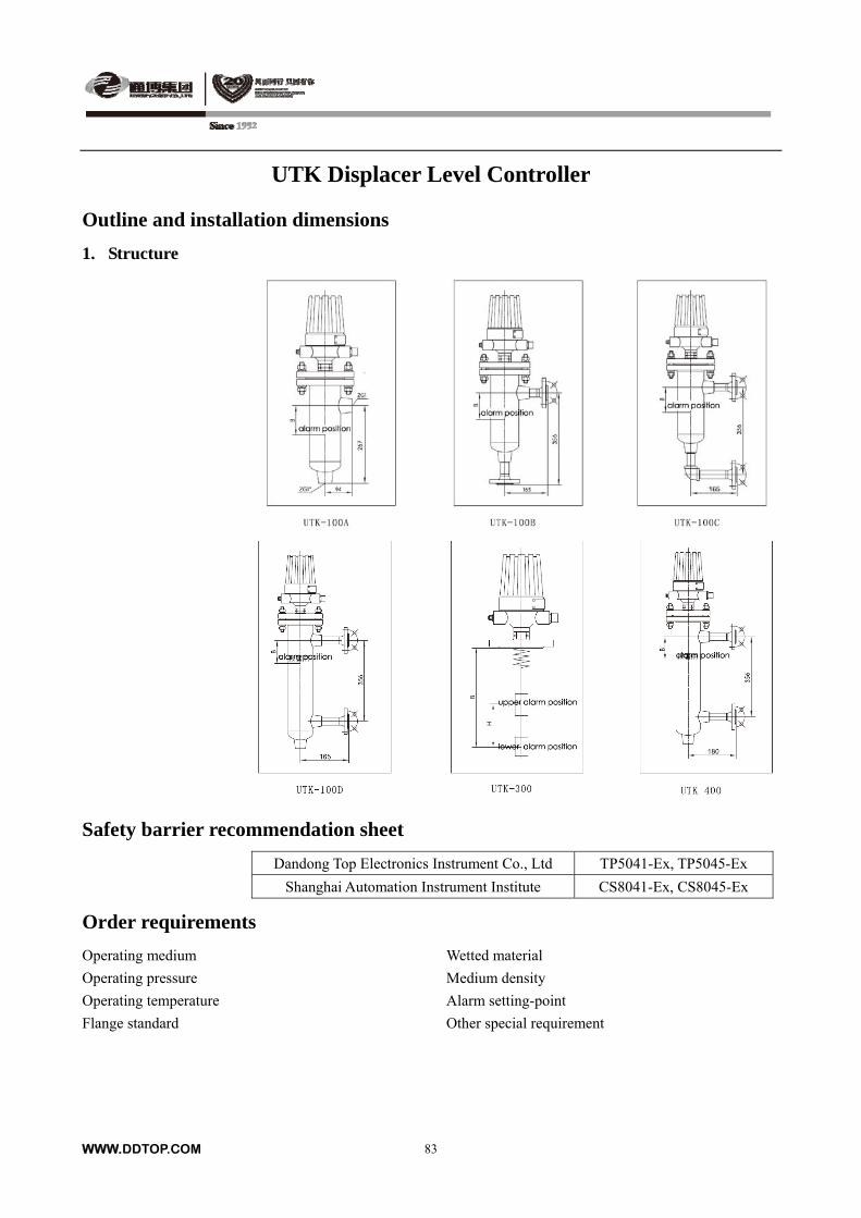
UTK Displacer Level Controller
Outline and installation dimensions
1. Structure
Safety barrier recommendation sheet
Dandong Top Electronics Instrument Co., Ltd TP5041-Ex, TP5045-Ex
Shanghai Automation Instrument Institute CS8041-Ex, CS8045-Ex
Order requirements
Operating medium Wetted material
Operating pressure Medium density
Operating temperature Alarm setting-point
Flange standard Other special requirement
WWW.DDTOP.COM 83
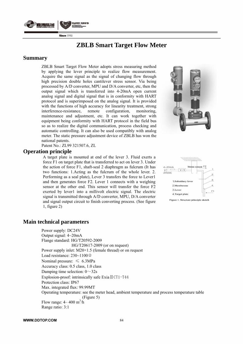
ZBLB Smart Target Flow Meter
Summary
ZBLB Smart Target Flow Meter adopts stress measuring method by applying the lever principle to realize flow measurement. Acquire the same signal as the signal of changing flow through high precision double holes cantilever stress sensor. Via being processed by A/D converter, MPU and D/A converter, etc, then the output signal which is transferred into 4-20mA open current analog signal and digital signal that is in conformity with HART protocol and is superimposed on the analog signal. It is provided with the functions of high accuracy for linearity treatment, strong interference-resistance, remote configuration, monitoring, maintenance and adjustment, etc. It can work together with equipment being conformity with HART protocol in the field bus so as to realize the digital communication, process checking and automatic controlling. It can also be used compatibly with analog meter. The static pressure adjustment device of ZBLB has won the national patents. Patent No.: ZL99 321507.6, ZL
Operation principle A target plate is mounted at end of the lever 3. Fluid exerts a force F1 on target plate that is transferred to act on lever 3. Under the action of force F1, shaft-seal 2 diaphragm as fulcrum (It has two functions: 1.Acting as the fulcrum of the whole lever. 2. Performing as a seal plate), Lever 3 transfers the force to Lever1 and then generates force F2. Lever 1 connects with a weighing sensor at the other end. This sensor will transfer the force F2 exerted by lever1 into a millivolt electric signal. The electric signal is transmitted through A/D converter, MPU, D/A converter and signal output circuit to finish converting process. (See figure 1, figure 2)
Main technical parameters
Power supply: DC24V Output signal: 4~20mA Flange standard: HG/T20592-2009 HG/T20617-2009 (or on request) Power supply inlet: M20×1.5 (female thread) or on request Load resistance: 230~1100Ω Nominal pressure: ≤ 6.3MPa Accuracy class: 0.5 class, 1.0 class Damping time selection: 0~32s Explosion-proof: intrinsically safe ExiaⅡCT1-T44 Protection class: IP67 Max. integrated flux: 99.99MT Operating temperature: see the meter head, ambient temperature and process temperature table
(Figure 5) Flow range: 4– 400 m3/h Range ratio: 3:1
WWW.DDTOP.COM
84
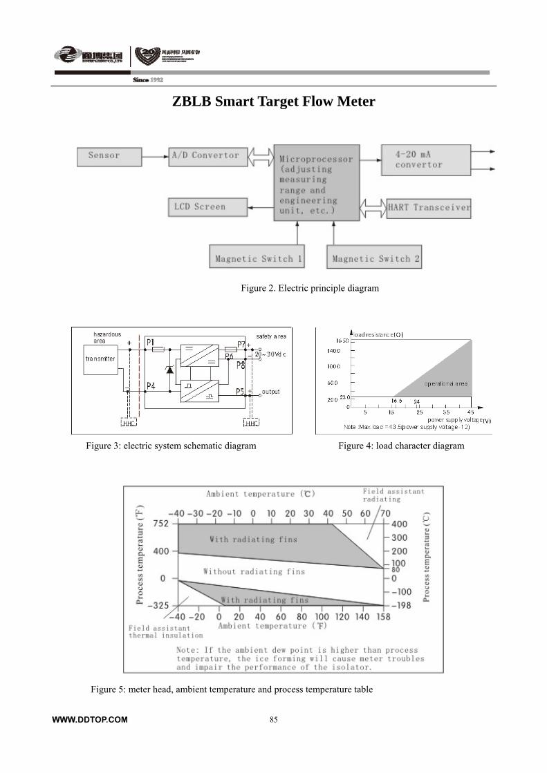
ZBLB Smart Target Flow Meter
Figure 2. Electric principle diagram
Figure 3: electric system schematic diagram Figure 4: load character diagram
Figure 5: meter head, ambient temperature and process temperature table
WWW.DDTOP.COM
85
WWW.DDTOP.COM
86
ZBLB Smart Target Flow Meter
Model selection table
Model Code Code meaning
ZBLB- Smart target flow meter
1 PN: 2.5MPa (class 150)
2 PN: 4.0MPa
3 PN: 6.3MPa (class 300)
015 DN15 (only for ring type measuring chamber)
025 DN25
040 DN40
050 DN50
080 DN80
100 DN100
150 DN150
200 DN200
A Ring type measuring chamber
B Straight pipe section measuring chamber
/
i Intrinsically safe
T Measuring chamber material: Carbon steel
H Measuring chamber material: 304, 316L or on request
D Without radiating fin, see figure 5 (T≤100)
G With radiating fin, see figure 5(100<T≤400)
X With auxiliary local device ( please note radiation or
insulation) see figure 5
Medium density: kg/m3
Q Max. volume flow m3/h (scale flow)
G Max. mass flow t/h (scale flow)
ZBLB- /
Example:
ZBLB-2050A/ iTD780G20 is smart target flow meter, nominal pressure is 4.0MPa, nominal diameter is
50mm, ring type measuring chamber, intrinsically safe, measuring chamber material is carbon steel,
measured medium temperature≤100, medium density is 780 kg/m3, max. mass flow is 20t/h.
ZBLB Smart Target Flow Meter
Flow table (calibrated fluid’s density is 839kg/m3)
Nominal diameter
DN(mm)
Target diameter
(mm)
β
β=d/D
Flow rate coefficient
K
C
14.129×D(1/β-β)
Flow rate range
m3/h
15 12 0.80 0.699 95.370 1.5,4.5
20 0.80 0.725 158.951 4,5,6.3 25
18 0.72 0.690 236.268 8
28 0.70 0.701 411.759 8 40
32 0.80 0.741 254.322 6.3
40 0.80 0.725 317.902 8,10,12.5
WWW.DDTOP.COM
87
35 0.70 0.675 514.699 16, 20 50
30 0.60 0.650 753.546 25
56 0.70 0.680 823.518 25,32
48 0.60 0.660 1205.674 40,50 80
40 0.50 0.660 1695.480 63
70 0.70 0.660 1029.398 40
60 0.60 0.660 1507.093 50,63
50 0.50 0.650 2119.350 80 100
40 0.40 0.650 2967.090 100
90 0.60 0.660 2260.640 80
75 0.50 0.660 3179.025 100,125 150
60 0.40 0.650 4450.635 160
70 0.35 0.660 7084.684 160,200,250 200
50 0.25 0.660 10596.750 300,400
Outline and installation dimension
ZBLB-A/D (ring-type measuring chamber)
L M Nominal diameter (mm)
Φ15 355 60
Φ25 365 60
Φ40 375 70
Φ50 400 70
Φ80 395 70
Φ100 415 90
Φ150 460 110
Φ200 505 120
XE
Φ124
L
M
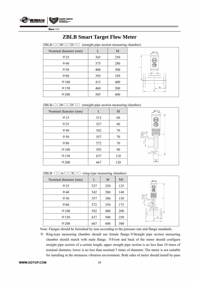
ZBLB Smart Target Flow Meter ZBLB-B/D (straight pipe section measuring chamber)
L M Nominal diameter (mm)
Φ25 365 250
Φ40 375 280
Φ50 400 300
Φ80 395 350
Φ100 415 400
Φ150 460 500
Φ200 505 600
EX
L
M
M1
Φ124
ZBLB-B/D (straight pipe section measuring chamber)
L M Nominal diameter (mm)
Φ15 512 60
Φ25 527 60
Φ40 542 70
Φ50 557 70
Φ80 572 70
Φ100 592 90
Φ150 637 110
Φ200 667 120
EX
LM
Φ124
L1
L2
ZG1/2"twoplaces
ZBLB-A/X (ring-type measuring chamber)
L M M1 Nominal diameter (mm)
WWW.DDTOP.COM
88
Φ25 527 250 125
Φ40 542 280 140
Φ50 557 300 150
Φ80 572 350 175
Φ100 592 400 200
Φ150 637 500 250
667 600 300
XE
M1
Φ124
M
L1
L
ZG1/2"
L2
twoplaces
Φ200
Note: Flanges should be furnished by user according to the pressure rate and flange standards.
※ Ring-type measuring chamber should use female flange.※Straight pipe section measuring
chamber should match with male flange. ※Front and back of the meter should configure
straight pipe section of a certain length, upper straight pipe section is no less than 10 times of
nominal diameter, lower is no less than nominal 5 times of diameter. The meter is not suitable
for installing in the strenuous vibration environment. Both sides of meter should install by-pass
WWW.DDTOP.COM
89
line.
Guard grating recommendation table
Dandong Top Electronics Instrument Co.,Ltd TP5041-Ex; TP5045-Ex
Shanghai Automation Instrument Institute GS8041-Ex; GS8037-Ex
TURCK company MK33-11Ex-Hli/24VDC
British MTL company MTL3046B; MTL5042
Germany P+F company KFD2-STC3-Ex1
Order Notice
Please fill in the blank when ordering.
Model Tag No. Quantity
Medium (kg/h)
Oper. Temper.
Max.Flow
(m3/h or N m3/h)
Oper. Press. (MPa) (kg/h)
Medium density (kg/m³or Kg/Nm³)Norm.Flow
(m3/h or N m3/h)
Kinematic Vis. (mm2/s) (kg/h)
Dynamic Vis. (mPa.s or mm2/s)Min. Flow
(m3/h or N m3/h)
Operation
Condition
Flange Stand.
Pipe state horizontal pipe
vertical pipe
Remark:
WWW.DDTOP.COM 90
EFTN target flow meter
Summary
EFTN target flow meter is flow measuring meter designed by ourselves, we all select large scale integrated circuit
and device manufactured by famous chip manufacturer in the world such as TI company,AD company and MAX
company, use Embedded Workbench compiling environment of IAR company to compile reliable EFTN working
procedure. EFTN can be used for measuring flow of liquid,gas and steam, and convert it to analog output signal
of 4-20mA. Not only have they the character of no moving part such as orifice plate and vortex street, but also
have perfect accuracy that can be compared with the precision of volume meter. Meanwhile, they have features of
anti-interference, dirty resistance proof, simpleness with good reliability. They can be widely used in petroleum,
chemical, energy, food, environment protection and water conservancy, etc.
Operating principle
EFTN target flow meter is composed of measuring chamber, force-summing element( target), sensing
element(force sensor, temperature sensor),transition parts( increase or decrease according to temperature and
pressure changes),calculation display and output part.
When fluid is flowing in measuring pipe, moment of force is generated by autologous kinetic energy and baffles
(target), its acting force is directly proportional to the square of the medium velocity. The mathematical expression
as follows:
F=CDAρU2/2
In form:F——resistance force on target
CD——object resistance coefficient
ρ——medium density in application
U——medium average velocity in measuring pipe
A——target axial projected area of measuring pipe
Main technical parameters
1. Main parameters
Have great high sensitivity. can measure extremely slow flow rate, even 0.8m/s
Measuring accurately, the accuracy is 0.5、1.0、1.5、2.5 class
Nominal diameter: 15-1200mm
Nominal pressure: ≤42.0MPa
Operating temperature: -196 ~ +450
Measuring medium: liquid,gas,steam
Have large measuring range, max. range is 1:10
Have excellent repeatability. The general repeatability is 0.1%
Have small pressure loss. The pressure loss is only about half of one with throttle orifice plate.
Compensation function: with temperature and pressure compensation
You can use dry calibration method, that is hanging weight method.
The measuring range can be changed by changing size of target plate according to actual requirement.

WWW.DDTOP.COM 91
Display in field and through remote communication
Explosion-proof: intrinsically safe type (ExiaⅡCT2~T6)
Explosion isolation type(ExdⅡCT2~T6)
Protection class: IP 67
2. Structure
1.measuring chamber 2.transition parts 3. integrating、display、output parts 4.junction box
Double clip type(A type) plug-in type(C type) online plug type(D type)
Model selection table
model code content
EFTN- EFTN target flow meter
1 2.0MPa(class 150)
2 2.5MPa
3 4.0MPa
4 6.3MPa(class 300)
5 10.0MPa(class 600)
6 16.0MPa(class 900)
7 25.0MPa(class 1500)
8 32.0MPa
9 42.0MPa(class 2500)
0 others
015 DN15
020 DN20
025 DN25
040 DN40
050 DN50
080 DN80
100 DN100
150 DN150
200 DN200
…
A Double clip type
B Straight pipe type
C50 Plug-in type DN50
C100 Plug-in type DN100
D50 Online plug type DN50
D100 Online plug type DN100
/
I Intrinsically safe type
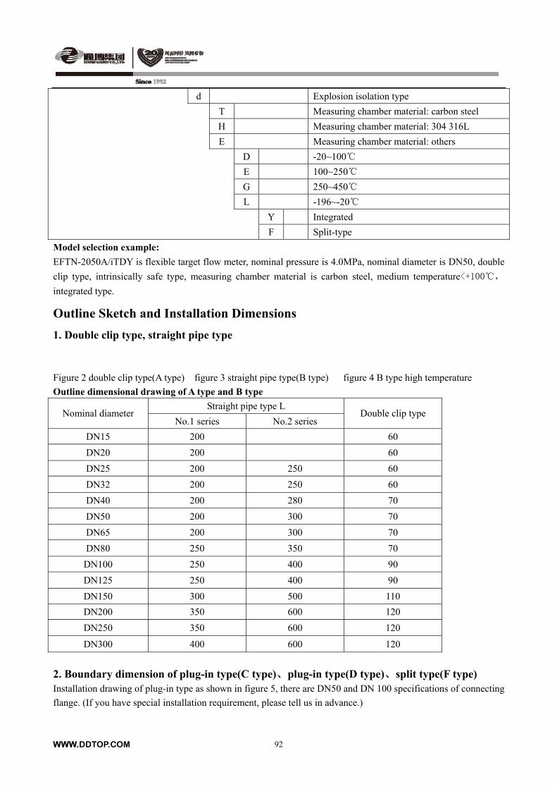
WWW.DDTOP.COM 92
d Explosion isolation type
T Measuring chamber material: carbon steel
H Measuring chamber material: 304 316L
E Measuring chamber material: others
D -20~100
E 100~250
G 250~450
L -196~-20
Y Integrated
F Split-type
Model selection example:
EFTN-2050A/iTDY is flexible target flow meter, nominal pressure is 4.0MPa, nominal diameter is DN50, double
clip type, intrinsically safe type, measuring chamber material is carbon steel, medium temperature<+100,
integrated type.
Outline Sketch and Installation Dimensions
1. Double clip type, straight pipe type
Figure 2 double clip type(A type) figure 3 straight pipe type(B type) figure 4 B type high temperature
Outline dimensional drawing of A type and B type
Straight pipe type L Nominal diameter
No.1 series No.2 series Double clip type
DN15 200 60
DN20 200 60
DN25 200 250 60
DN32 200 250 60
DN40 200 280 70
DN50 200 300 70
DN65 200 300 70
DN80 250 350 70
DN100 250 400 90
DN125 250 400 90
DN150 300 500 110
DN200 350 600 120
DN250 350 600 120
DN300 400 600 120
2. Boundary dimension of plug-in type(C type)、plug-in type(D type)、split type(F type) Installation drawing of plug-in type as shown in figure 5, there are DN50 and DN 100 specifications of connecting
flange. (If you have special installation requirement, please tell us in advance.)
WWW.DDTOP.COM 93
Installation drawing of online plug type as shown in figure 6, there are DN50 and DN100 specifications of
connecting flange, cut-off valve is ball vlave.
Welding drawing of process short pipe and connecting flange as shown in figure 7. (If you have special
installation requirement, please tell us in advance.)
Order notice
EFTN target flow meter is suitable for many occasions and measuring many mediums. To ensure you have
satisfied effects in use, we suggest you should notice the following items when selecting model.
1) Make sure frequently-used flow needed, and ensure the max.flow according to 1.5to 2.5 times of
frequently-used flow.
2) Point out the installing flange standard, sealing type, especially the requirement for special installation, please
tell us clearly.
3) When customers ordering the goods, please point out the mediums of measuring fluid and their densities.
4) For servicing and using the meter conveniently, both sides of the meter should be installed by-pass pipe. If
there is no by-pass pipe, we suggest selecting online plug-in type target flow meter.
5) If you need to measure special fluid, in addition to selecting measuring pipe material is provided by company,
you can recommend the measuring pipe material needed directly.
Attached table 1: Flow range table Attached table 1 current measuring range in standard conditions table
Target diameter ratio range Diameter of flow
meter(mm)
Measuring range
of flow meter
(m3/h) βmax βmax
Max.press. lossΔ
Pmax(Kpa)
15(1/2″) 0.1~3 0.8 0.6 96.4
20(3/4″) 0.17~5 0.8 0.6 55.12
25(1″) 0.3~9 0.8 0.6 34.45
32(11/2″) 0.5~14 0.8 0.6 24.12
40(13/4″) 1.0~24 0.8 0.5 17.23
50(2″) 1.5~40 0.8 0.5 6.89
65 2.5~60 0.7 0.4 5.51
80 3.5~90 0.7 0.4 4.31
100 5~140 0.7 0.4 2.76
125 6~200 0.7 0.4 2.07
150 10~300 0.6 0.3 1.38
200 18~560 0.6 0.3 0.89
250 25~800 0.5 0.3 0.56
300 40~1200 0.5 0.25 0.35
350 50~1500 0.5 0.25 0.10
400 65~2000 0.5 0.25 0.07
WWW.DDTOP.COM 94
450 90~2600 0.4 0.25 0.06
500 110~3300 0.4 0.2 0.05
550 140~4100 0.35 0.2 0.04
600 170~5000 0.3 0.2 0.03
700 230~6800 0.3 0.2 0.011
800 300~9000 0.3 0.2 0.0083
900 370~11000 0.3 0.2 0.0062
1000 470~14000 0.2 0.1 0.0055
1100 560~16000 0.2 0.1 0.0041
1200 670~20000 0.2 0.1 0.0034
1300 780~23000 0.2 0.1 0.0028
1400 900~27000 0.2 0.1 0.0028
1500 1050~31000 0.2 0.1 0.0021
Attached table 2 Saturated steam flow measuring range under the pressure of operating condition table
Measuring range t/h Nominal
diameter
mm 0.1MP
a 0.2MPa 0.3MPa 0.4MPa 0.5MPa 0.6MPa 0.8MPa 1.0MPa 1.5MPa 2.0MPa
15 0.002~
0.02
0.003~0.0
6
0.005~
0.05
0.007~
0.07
0.008~
0.08
0.009~
0.09
0.012~
0.12
0.015~
0.15
0.023~
0.23 0.03~0.3
20 0.003~
0.03
0.006~0.0
6
0.009~
0.09
0.012~
0.12
0.015~
0.15
0.017~
0.17
0.022~
0.22
0.028~
0.28
0.04~0.
4 0.055~0.55
25 0.005~
0.05
0.009~0.0
9
0.014~
0.14
0.019~
0.19
0.02~0.
2
0.027~
0.27
0.035~
0.35
0.044~
0.4
0.065~
0.65 0.085~0.85
32 0.008~
0.08
0.016~0.1
6
0.023~
0.23
0.032~
0.32
0.036~
0.36
0.044~
0.44
0.056~
0.56
0.072~
0.72 0.1~1.0 0.14~1.4
40 0.012~
0.12
0.026~0.2
5
0.036~
0.36
0.045~
0.45
0.058~
0.58
0.069~
0.69
0.09~0.
9
0.11~1.
1
0.16~1.
6 0.22~2.2
50 0.02~0.
2
0.038~0.3
8
0.057~
0.57
0.075~
0.75
0.09~0.
9 0.1~1.0
0.14~1.
4
0.17~1.
4
0.25~2.
6 0.34~3.4
65 0.035
~0.35
0.065 ~
0.65
0.1 ~
1.0
0.13 ~
1.3
0.15 ~
1.5
0.18 ~
1.8
0.24 ~
2.4
0.29 ~
2.9
0.44 ~
4.4 0.58~5.8
80 0.05 ~
0.5 0.1~1.0
0.15 ~
1.5
0.18 ~
1.8
0.23 ~
2.3
0.27 ~
2.7
0.36 ~
3.6
0.45 ~
4.5
0.65 ~
6.5 0.88~8.8
WWW.DDTOP.COM 95
100 0.08 ~
0.8 0.15~1.5
0.23 ~
2.3
0.28 ~
2.8
0.36 ~
3.6
0.42 ~
4.2
0.56 ~
5.6
0.7 ~
7.0 1.0~10 1.3~13
125 0.12 ~
1.2 0.24~2.4
0.35 ~
3.5
0.48 ~
4.8
0.56 ~
5.6
0.68 ~
6.8
0.89 ~
8.9 1.1~11 1.6~16 2.1~21
150 0.18 ~
1.8 0.35~3.5
0.5 ~
5.0
0.7 ~
7.0
0.82 ~
8.2
0.96 ~
9.6 1.2~12 1.5~15 2.3~23 3.1~31
200 0.32 ~
3.2 0.6~6.0
0.9 ~
9.0 1.2~12 1.4~14 1.7~17 2.2~22 2.8~28 4.1~41 5.5~55
250 0.5 ~
5.0 1.0~10 1.4~14 1.9~19 2.2~22 2.7~27 3.5~35 4.4~44 6.5~65 8.6~86
300 0.7 ~
7.0 0.14~1.4 2.0~20 2.5~25 3.3~33 3.9~39 5~50 6.2~62 9.2~92 12~120
350 1 ~
10.0 1.9~19 2.8~28 3.5~35 4.4~44 5.2~52 7~70 8.5~85
12 ~
120 27~270
400 1.3~13 2.5~25 3.6~36 4.7~47 5.8~58 6.8~68 9~90 11~110 16~160 22~220
450 1.6~16 3.1~31 4.6~46 6.0~60 7.4~74 8.6~86 11~110 14~140 21~120 27~270
500 1.6~16 3.8~38 5.6~56 7.0~70 9.1~91 10~100 14~140 17~170 26~260 34~340
550 2.5~25 4.7~47 6.8~68 9.0~90 11~110 13~130 17~170 20~200 31~310 41~410
600 3~30 3.6~36 8.2~82 10~100 13~130 15~150 20~200 25~250 37~370 49~490
Attached table 3 standard dry air flow range of working condition table Measuring range NM3/H Nominal
diameter
mm 0.01 MPa 0.1 MPa 0.2 MPa 0.3 MPa 0.4 MPa 0.6 MPa 0.8 MPa 1.0 MPa 2.0 MPa 4.0 MPa
15 2~20 4~40 6~60 8~80 10~100 14~140 18~180 22~220 42~420 82~820
20 3~30 6~60 9~90 12~120 15~150 21~210 27~270 33~330 63~630123~
1230
25 5~50 10~100 15~150 20~200 25~250 35~350 45~450 55~550 105~
1050
205~
2050
32 8~80 16~160 24~240 32~320 40~400 56~560 72~720 88~880 168~
1680
328~
3280
40 13~130 26~260 39~390 42~420 65~650 91~910117~
1170
143~
1430
273~
2730
533~
5330
50 13~130 40~400 60~600 80~800100~
1000
140~
1400
180~
1800
220~
2200
420~
4200
820~
8200
80 50~500 100~
1000
150~
1500
200~
2000
250~
2500
350~
3500
450~
4500
550~
5500
1050~
10500
2050~
20500
100 80~800 160~
1600
240~
2400
320~
3200
400~
4000
560~
5600
720~
7200
880~
8800
1680~
16800
3280~
32800
WWW.DDTOP.COM 96
150 180~
1800
360~
3600
540~
5400
720~
7200
900~
9000
1260~
12600
1620~
16200
1980~
19800
3780~
37800
7380~
73800
200 300~
3000
600~
6000
900~
9000
1200~
12000
1500~
15000
2100~
21000
2700~
27000
3300~
33000
6300~
63000
12300~
123000
250 500~
5000
1000~
10000
1500~
15000
2000~
20000
2500~
25000
3500~
35000
4500~
45000
5500~
55000
10500~
105000
20500~
205000
300 750~
7500
1500~
15000
2250~
22500
3000~
30000
3750~
37500
5250~
52500
6750~
67500
8250~
82500
15750~
157500
30750~
307500
350 1000~
10000
2000~
20000
3000~
30000
4000~
40000
5000~
50000
7000~
70000
9000~
90000
11000~
110000
21000~
210000
41000~
410000
400 1300~
13000
2600~
26000
3900~
39000
4200~
42000
6500~
65000
9100~
91000
11700~
117000
14300~
1430000
27300~
273000
53300~
533000
450 1700~
17000
3400~
34000
5100~
51000
6000~
60000
8500~
85000
11900~
119000
15300~
153000
18700~
187000
35700~
357000
69700~
697000
500 2000~
20000
4000~
40000
6000~
60000
8000~
80000
10000~
100000
14000~
140000
18000~
180000
22000~
220000
42000~
420000
82000~
820000
550 2500~
25000
5000~
50000
7500~
75000
10000~
100000
12500~
125000
17500~
175000
22500~
225000
27500~
275000
52500~
525000
102500~
1025000
600 3000~
30000
6000~
60000
9000~
90000
12000~
120000
15000~
150000
21000~
210000
25000~
250000
33000~
330000
63000~
630000
123000~
1230000
700 4000~
40000
8000~
80000
12000~
1200000
16000~
160000
20000~
200000
28000~
280000
36000~
360000
44000~
440000
84000~
840000
164000~
1640000
800 5000~
50000
10000~
100000
15000~
150000
20000~
200000
25000~
250000
35000~
350000
45000~
450000
55000~
550000
95000~
950000
205000~
2050000
900 6500~
65000
13000~
130000
19500~
195000
26000~
260000
32500~
325000
45500~
455000
58500~
585000
71500~
715000
136500~
1365000
266500~
2665000
1000 8000~
80000
16000~
160000
24000~
240000
32000~
320000
40000~
400000
56000~
560000
72000~
720000
88000~
880000
168000~
1680000
328000~
3280000
Note: In the table , air temperature is 20, absolute pressure is 0.101MPa under standard air flow range. Main connection and outline dimension of product.
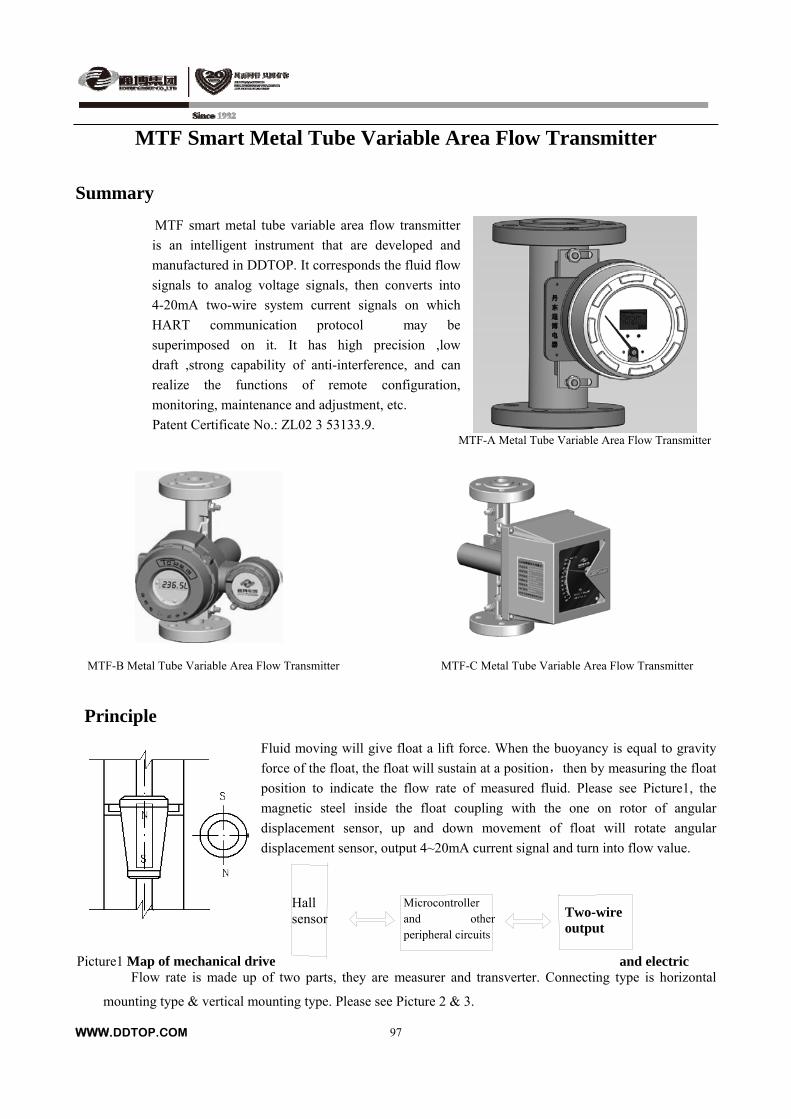
MTF Smart Metal Tube Variable Area Flow Transmitter
Summary
MTF smart metal tube variable area flow transmitter
is an intelligent instrument that are developed and
manufactured in DDTOP. It corresponds the fluid flow
signals to analog voltage signals, then converts into
4-20mA two-wire system current signals on which
HART communication protocol may be
superimposed on it. It has high precision ,low
draft ,strong capability of anti-interference, and can
realize the functions of remote configuration,
monitoring, maintenance and adjustment, etc.
Patent Certificate No.: ZL02 3 53133.9. MTF-A Metal Tube Variable Area Flow Transmitter
MTF-B Metal Tube Variable Area Flow Transmitter MTF-C Metal Tube Variable Area Flow Transmitter
Principle
Fluid moving will give float a lift force. When the buoyancy is equal to gravity
force of the float, the float will sustain at a position,then by measuring the float
position to indicate the flow rate of measured fluid. Please see Picture1, the
magnetic steel inside the float coupling with the one on rotor of angular
displacement sensor, up and down movement of float will rotate angular
displacement sensor, output 4~20mA current signal and turn into flow value.
WWW.DDTOP.COM
97
Picture1 Map of mechanical drive and electric
Microcontroller and other peripheral circuits
Two-wire output
Hall sensor
Flow rate is made up of two parts, they are measurer and transverter. Connecting type is horizontal
mounting type & vertical mounting type. Please see Picture 2 & 3.
WWW.DDTOP.COM
98
MTF Smart Metal Tube Variable Area Flow Transmitter
Main technical parameters:
1. Main parameters
Operating voltage: DC24V
Output signal: two wires, 4~20mA DC+ HART
Flange standard: HG/T20592-2009; HG/T20617-2009 (or on request)
Power supply inlet: M20×1.5(Female) or on request
Input resistance: >100MΩ;
Standard load resistance: 250Ω
Nominal pressure: DN15-DN50:PN≤10.0MPa; DN80-DN100:PN≤6.3MPa
Precision: 1.0% FS (diameter of DN15 and DN 20 is 2.0% FS)
Operating temperature: -40~+300。
Damping period: (0-32s)
Ambient temperature: -40~+70(LCD:-20~+70)
Explosion- proof type: Intrinsically safe explosion type: Exia CT4; Isolation explosion type: Ⅱ
Exd CT4Ⅱ
Protection class: IP67 Flow rate range
Water: 2.5 L/h --100000L/h(20 )
Air: 0.07--1800m3/h(0.1013MPa, 20)
Applicable fluid viscosity
DN15、DN20:η<5mPa.s(FZ15.1,FZ15.2,FZ15.3)
η<30mpa.s(FZ15.4,FZ15.5,FZ15.6,FZ15.7,FZ15.8、FZ20.1、FZ20.2)
DN25、DN40: η<250mPa.s
DN50~DN100: η<300mPa.s
2. Type
By mounting way: horizontal mounting type & vertical mounting type
By fluid:
Basic type: For liquid measuring.
With damping type: For gas & steam measuring.
Anti-corrosion type: Lining Teflon (PTFE), for corrosive medium measuring.
Jacket type: For fluid needs staying warm or cool condition.
Attention: (Anti-corrosion type& jacket type has no horizontal mounting type.)
WWW.DDTOP.COM
99
MTF Smart Metal Tube Variable Area Flow Transmitter
Model Selection Table
1. Model Selection Table
Model Code Content
A With local indicator & remote transducer (dual display) Metal Tube Variable Area FlowTransmitter
B With remote transducer (digital display) Metal Tube Variable Area Flow Transmitter
MTF -
C With local indicator (pointer indication) Metal Tube Variable Area Flow Transmitter
1 1.6MPa
2 2.5Mpa (class150)
3 4.0MPa
4 6.3Mpa (class300)
5 10.0Mpa (class600)
015 DN15
020 DN20
025 DN25
040 DN40
050 DN50
080 DN80
100 DN100
H Wetted material: 304
R Wetted material:316L
P Wetted material: Teflon ( PTFE)
Q Other materials:
/
i Intrinsically safe type
d Isolating explosion type
D Fluid temperature: 0~200
G Fluid temperature:-40-0 200-300
Z With damping type
W Without damping type
S Horizontal mounting type
C Vertical mounting type
MTF - /
Model selection sample: MTF-A1025H/dDWC is Metal Tube Variable Area Flow Transmitter, with local
indicator & remote transducer , flange is PN1.6 , DN25, wetted material is 304, isolating explosion type, operation
temperature 0~200, without damping type, vertical mounting type.

WWW.DDTOP.COM
100
MTF Smart Metal Tube Variable Area Flow Transmitter 2. Model selection of flow value
Flow value(Water--L/h;Air--m3/h) Pressure loss -- kPa
Water calibration Air calibration Water calibration Air calibration
Float material Float material
Nominal
diameter Float code
304 PTFE 304 304 PTFE 304
FZ15.1 25 - 0.7 6.5 - 7.1
FZ15.2 40 25 1.1 6.5 5.5 7.2
FZ15.3 60 40 1.8 6.6 5.5 7.3
FZ15.4 100 60 2.8 6.6 5.6 7.5
FZ15.5 160 100 4.0 6.8 5.6 8.0
FZ15.6 250 160 7.0 7.2 5.8 10.0
FZ15.7 400 250 10.0 8.6 6.1 10.8
DN15
FZ15.8 600 400 16.0 11.1 7.3 14.0
FZ20.1 750 600 20 6.9 5.9 7.3 DN20
FZ20.2 1600 1000 34 7.8 6.2 8.2
FZ25.1 1000 600 30 7.0 5.5 7.7
FZ25.2 1600 1000 45 8.0 5.6 8.8
FZ25.3 2500 1600 70 10.8 5.6 12.0
FZ25.4 4000 2500 110 18.8 6.4 19.0
DN25
FZ25.5 6000 4000 180 20.0 10.0 25.0
FZ40.1 2750 1850 90 7.2 6.2 7.8
FZ40.2 5000 2750 150 7.5 6.5 8.5
FZ40.3 6500 5000 210 8.3 7.1 9.4 DN40
FZ40.4 8500 6500 320 9.8 8.5 10.3
FZ50.1 6000 4000 180 8.1 6.8 8.6
FZ50.2 10000 6000 300 11.0 8.8 10.4 DN50
FZ50.3 16000 10000 600 17.0 13.7 15.5
FZ80.1 25000 16000 1000 8.1 6.3 8.0 DN80
FZ80.2 40000 25000 1200 9.5 7.2 14.0
FZ100.1 60000 40000 1800 10.0 7.9 25.0 DN100
FZ100.2 100000 - - 15.0 - -
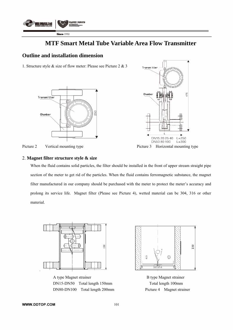
MTF Smart Metal Tube Variable Area Flow Transmitter
Outline and installation dimension
WWW.DDTOP.COM
101
1. Structure style & size of flow meter: Please see Picture 2 & 3
Picture 2 Vertical mounting type Picture 3 Horizontal mounting type
2. Magnet filter structure style & size
When the fluid contains solid particles, the filter should be installed in the front of upper stream straight pipe
section of the meter to get rid of the particles. When the fluid contains ferromagnetic substance, the magnet
filter manufactured in our company should be purchased with the meter to protect the meter’s accuracy and
prolong its service life. Magnet filter (Please see Picture 4), wetted material can be 304, 316 or other
material.
A type Magnet strainer B type Magnet strainer
DN15-DN50 Total length 150mm Total length 100mm
DN80-DN100 Total length 200mm Picture 4 Magnet strainer
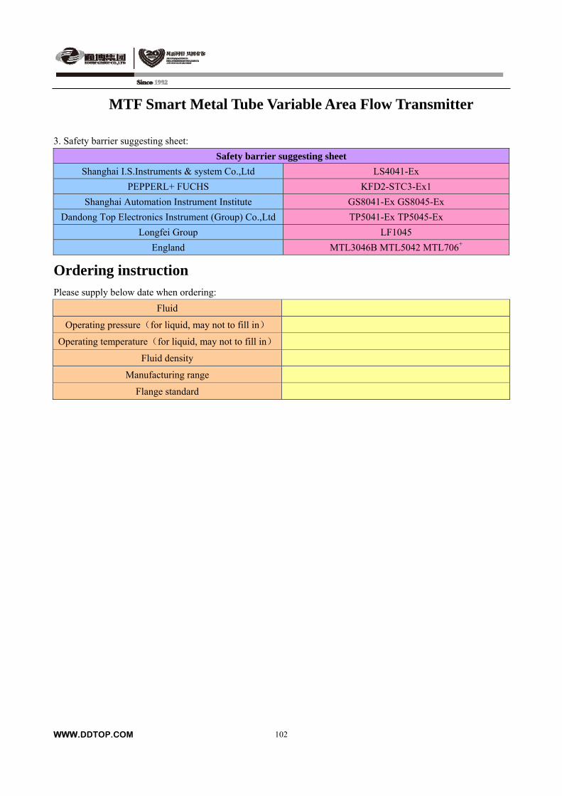
WWW.DDTOP.COM
102
MTF Smart Metal Tube Variable Area Flow Transmitter
3. Safety barrier suggesting sheet:
Safety barrier suggesting sheet
Shanghai I.S.Instruments & system Co.,Ltd LS4041-Ex
PEPPERL+ FUCHS KFD2-STC3-Ex1
Shanghai Automation Instrument Institute GS8041-Ex GS8045-Ex
Dandong Top Electronics Instrument (Group) Co.,Ltd TP5041-Ex TP5045-Ex
Longfei Group LF1045
England MTL3046B MTL5042 MTL706+
Ordering instruction Please supply below date when ordering:
Fluid
Operating pressure(for liquid, may not to fill in)
Operating temperature(for liquid, may not to fill in)
Fluid density
Manufacturing range
Flange standard
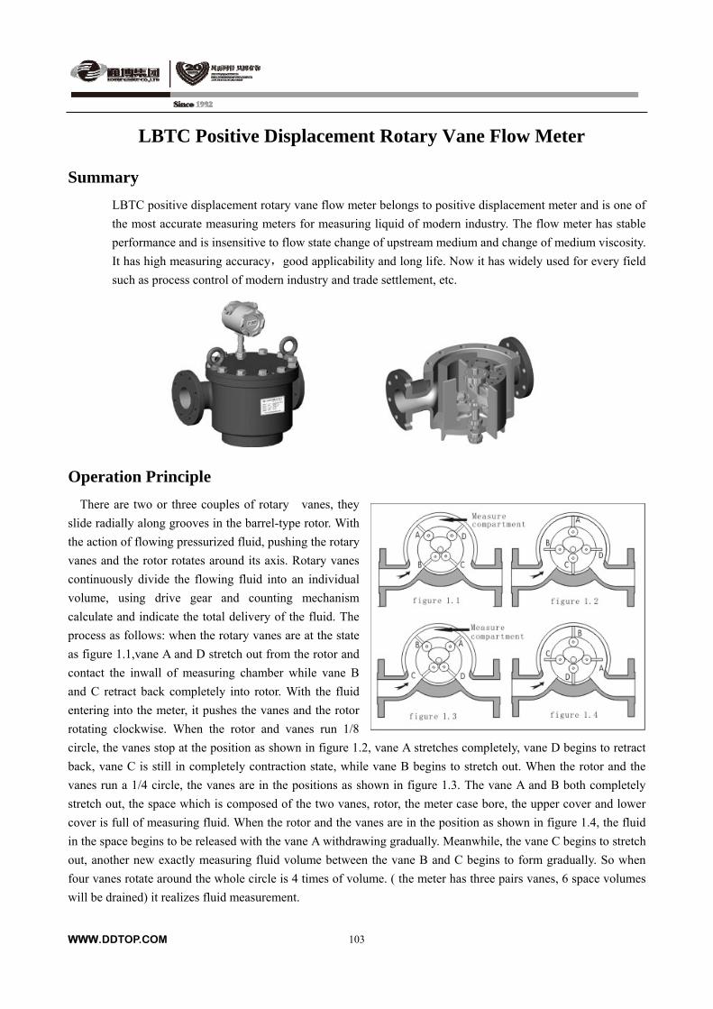
LBTC Positive Displacement Rotary Vane Flow Meter
Summary
LBTC positive displacement rotary vane flow meter belongs to positive displacement meter and is one of
the most accurate measuring meters for measuring liquid of modern industry. The flow meter has stable
performance and is insensitive to flow state change of upstream medium and change of medium viscosity.
It has high measuring accuracy,good applicability and long life. Now it has widely used for every field
such as process control of modern industry and trade settlement, etc.
Operation Principle
There are two or three couples of rotary vanes, they
slide radially along grooves in the barrel-type rotor. With
the action of flowing pressurized fluid, pushing the rotary
vanes and the rotor rotates around its axis. Rotary vanes
continuously divide the flowing fluid into an individual
volume, using drive gear and counting mechanism
calculate and indicate the total delivery of the fluid. The
process as follows: when the rotary vanes are at the state
as figure 1.1,vane A and D stretch out from the rotor and
contact the inwall of measuring chamber while vane B
and C retract back completely into rotor. With the fluid
entering into the meter, it pushes the vanes and the rotor
rotating clockwise. When the rotor and vanes run 1/8
circle, the vanes stop at the position as shown in figure 1.2, vane A stretches completely, vane D begins to retract
back, vane C is still in completely contraction state, while vane B begins to stretch out. When the rotor and the
vanes run a 1/4 circle, the vanes are in the positions as shown in figure 1.3. The vane A and B both completely
stretch out, the space which is composed of the two vanes, rotor, the meter case bore, the upper cover and lower
cover is full of measuring fluid. When the rotor and the vanes are in the position as shown in figure 1.4, the fluid
in the space begins to be released with the vane A withdrawing gradually. Meanwhile, the vane C begins to stretch
out, another new exactly measuring fluid volume between the vane B and C begins to form gradually. So when
four vanes rotate around the whole circle is 4 times of volume. ( the meter has three pairs vanes, 6 space volumes
will be drained) it realizes fluid measurement.
WWW.DDTOP.COM
103
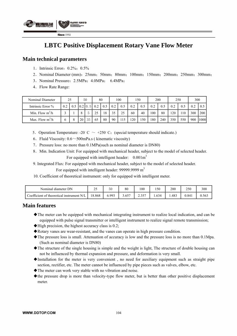
WWW.DDTOP.COM
104
LBTC Positive Displacement Rotary Vane Flow Meter
Main technical parameters
1.Intrinsic Error:0.2%;0.5%
2.Nominal Diameter (mm):25mm;50mm;80mm;100mm;150mm;200mm;250mm;300mm;
3.Nominal Pressure:2.5MPa;4.0MPa; 6.4MPa;
4.Flow Rate Range:
Nominal Diameter 25 50 80 100 150 200 250 300
Intrinsic Error % 0.2 0.5 0.2 0.5 0.2 0.5 0.2 0.5 0.2 0.5 0.2 0.5 0.2 0.5 0.2 0.5
Min. Flow m3/h 3 1 8 5 25 18 35 25 60 40 100 80 120 110 300 200
Max. Flow m3/h 6 8 20 35 65 80 90 115 120 150 180 240 350 550 900 1000
5.Operation Temperature: -20。C ~ +250。C;(special temperature should indicate.)
6.Fluid Viscosity: 0.6~500mPa.s ( kinematic viscosity)
7.Pressure loss: no more than 0.1MPa(such as nominal diameter is DN80)
8.Min. Indication Unit: For equipped with mechanical header, subject to the model of selected header.
For equipped with intelligent header: 0.001m3
9. Integrated Flux: For equipped with mechanical header, subject to the model of selected header.
For equipped with intelligent header: 99999.9999 m3
10. Coefficient of theoretical instrument: only for equipped with intelligent meter.
Nominal diameter DN 25 50 80 100 150 200 250 300
Coefficient of theoretical instrument N/L 18.868 6.993 3.657 2.357 1.634 1.483 0.841 0.563
Main features
The meter can be equipped with mechanical integrating instrument to realize local indication, and can be equipped with pulse signal transmitter or intelligent instrument to realize signal remote transmission;
High precision, the highest accuracy class is 0.2; Rotary vanes are wear-resistant, and the vanes can operate in high pressure condition. The pressure loss is small. Attenuation of accuracy is low and the pressure loss is no more than 0.1Mpa.
(Such as nominal diameter is DN80) The structure of the single housing is simple and the weight is light, The structure of double housing can
not be influenced by thermal expansion and pressure, and deformation is very small. Installation for the meter is very convenient , no need for auxiliary equipment such as straight pipe
section, rectifier, etc. The meter cannot be influenced by pipe pieces such as valves, elbow, etc. The meter can work very stable with no vibration and noise. the pressure drop is more than velocity-type flow meter, but is better than other positive displacement
meter.
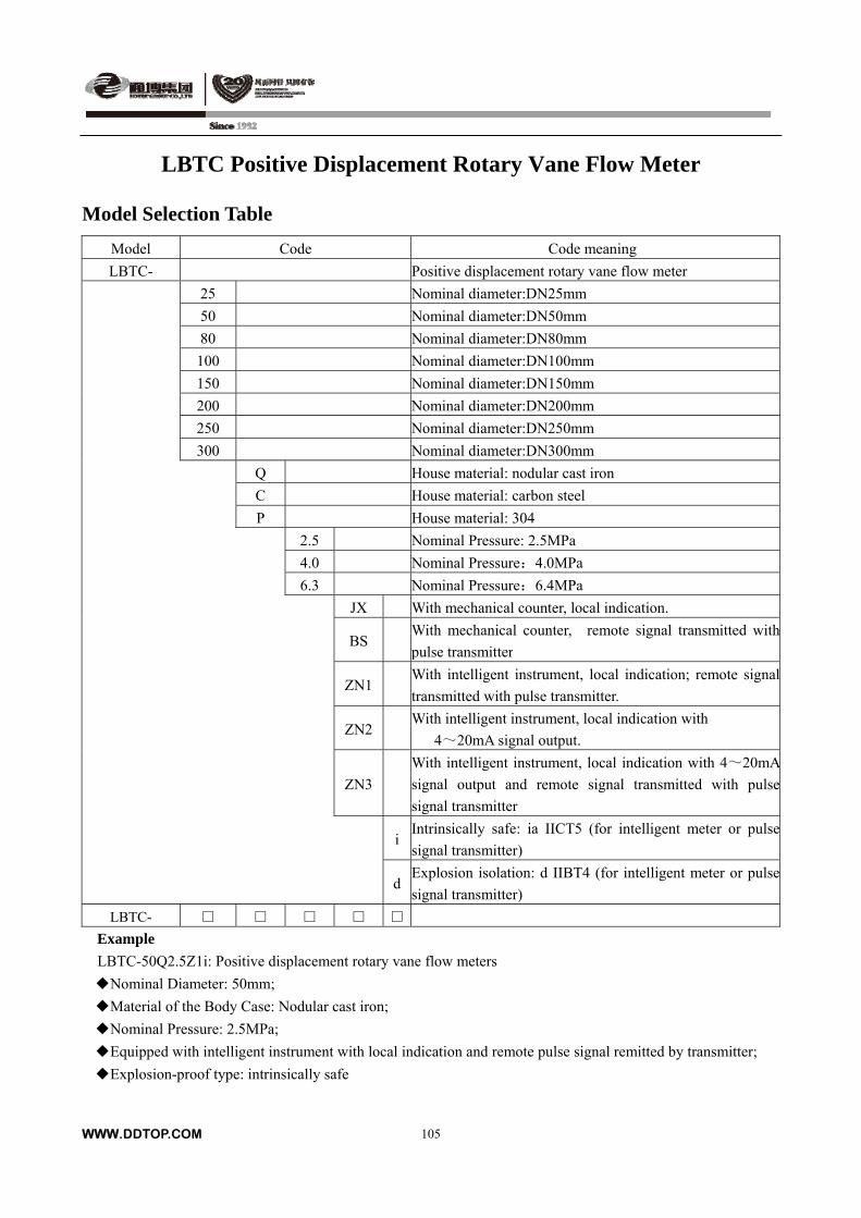
WWW.DDTOP.COM
105
LBTC Positive Displacement Rotary Vane Flow Meter
Model Selection Table
Model Code Code meaning
LBTC- Positive displacement rotary vane flow meter
25 Nominal diameter:DN25mm
50 Nominal diameter:DN50mm
80 Nominal diameter:DN80mm
100 Nominal diameter:DN100mm
150 Nominal diameter:DN150mm
200 Nominal diameter:DN200mm
250 Nominal diameter:DN250mm
300 Nominal diameter:DN300mm
Q House material: nodular cast iron
C House material: carbon steel
P House material: 304
2.5 Nominal Pressure: 2.5MPa
4.0 Nominal Pressure:4.0MPa
6.3 Nominal Pressure:6.4MPa
JX With mechanical counter, local indication.
BS With mechanical counter, remote signal transmitted with
pulse transmitter
ZN1 With intelligent instrument, local indication; remote signal
transmitted with pulse transmitter.
ZN2 With intelligent instrument, local indication with
4~20mA signal output.
ZN3
With intelligent instrument, local indication with 4~20mA
signal output and remote signal transmitted with pulse
signal transmitter
iIntrinsically safe: ia IICT5 (for intelligent meter or pulse
signal transmitter)
dExplosion isolation: d IIBT4 (for intelligent meter or pulse
signal transmitter)
LBTC-
Example
LBTC-50Q2.5Z1i: Positive displacement rotary vane flow meters
Nominal Diameter: 50mm;
Material of the Body Case: Nodular cast iron;
Nominal Pressure: 2.5MPa;
Equipped with intelligent instrument with local indication and remote pulse signal remitted by transmitter;
Explosion-proof type: intrinsically safe
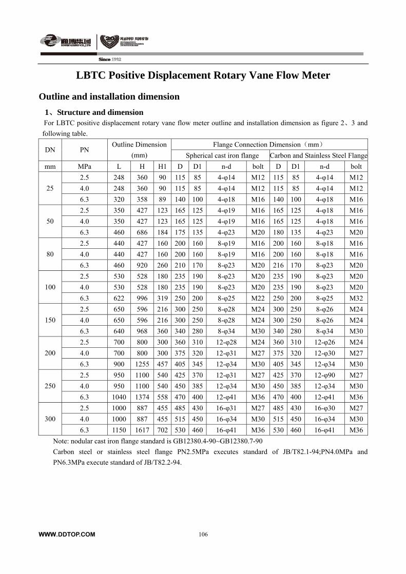
WWW.DDTOP.COM
106
LBTC Positive Displacement Rotary Vane Flow Meter
Outline and installation dimension
1、Structure and dimension For LBTC positive displacement rotary vane flow meter outline and installation dimension as figure 2、3 and
following table.
Flange Connection Dimension(mm) DN PN
Outline Dimension
(mm) Spherical cast iron flange Carbon and Stainless Steel Flange
mm MPa L H H1 D D1 n-d bolt D D1 n-d bolt
2.5 248 360 90 115 85 4-φ14 M12 115 85 4-φ14 M12
4.0 248 360 90 115 85 4-φ14 M12 115 85 4-φ14 M1225
6.3 320 358 89 140 100 4-φ18 M16 140 100 4-φ18 M16
2.5 350 427 123 165 125 4-φ19 M16 165 125 4-φ18 M16
4.0 350 427 123 165 125 4-φ19 M16 165 125 4-φ18 M1650
6.3 460 686 184 175 135 4-φ23 M20 180 135 4-φ23 M20
2.5 440 427 160 200 160 8-φ19 M16 200 160 8-φ18 M16
4.0 440 427 160 200 160 8-φ19 M16 200 160 8-φ18 M1680
6.3 460 920 260 210 170 8-φ23 M20 216 170 8-φ23 M20
2.5 530 528 180 235 190 8-φ23 M20 235 190 8-φ23 M20
4.0 530 528 180 235 190 8-φ23 M20 235 190 8-φ23 M20100
6.3 622 996 319 250 200 8-φ25 M22 250 200 8-φ25 M32
2.5 650 596 216 300 250 8-φ28 M24 300 250 8-φ26 M24
4.0 650 596 216 300 250 8-φ28 M24 300 250 8-φ26 M24150
6.3 640 968 360 340 280 8-φ34 M30 340 280 8-φ34 M30
2.5 700 800 300 360 310 12-φ28 M24 360 310 12-φ26 M24
4.0 700 800 300 375 320 12-φ31 M27 375 320 12-φ30 M27200
6.3 900 1255 457 405 345 12-φ34 M30 405 345 12-φ34 M30
2.5 950 1100 540 425 370 12-φ31 M27 425 370 12-φ90 M27
4.0 950 1100 540 450 385 12-φ34 M30 450 385 12-φ34 M30250
6.3 1040 1374 558 470 400 12-φ41 M36 470 400 12-φ41 M36
2.5 1000 887 455 485 430 16-φ31 M27 485 430 16-φ30 M27
4.0 1000 887 455 515 450 16-φ34 M30 515 450 16-φ34 M30300
6.3 1150 1617 702 530 460 16-φ41 M36 530 460 16-φ41 M36
Note: nodular cast iron flange standard is GB12380.4-90~GB12380.7-90
Carbon steel or stainless steel flange PN2.5MPa executes standard of JB/T82.1-94;PN4.0MPa and
PN6.3MPa execute standard of JB/T82.2-94.
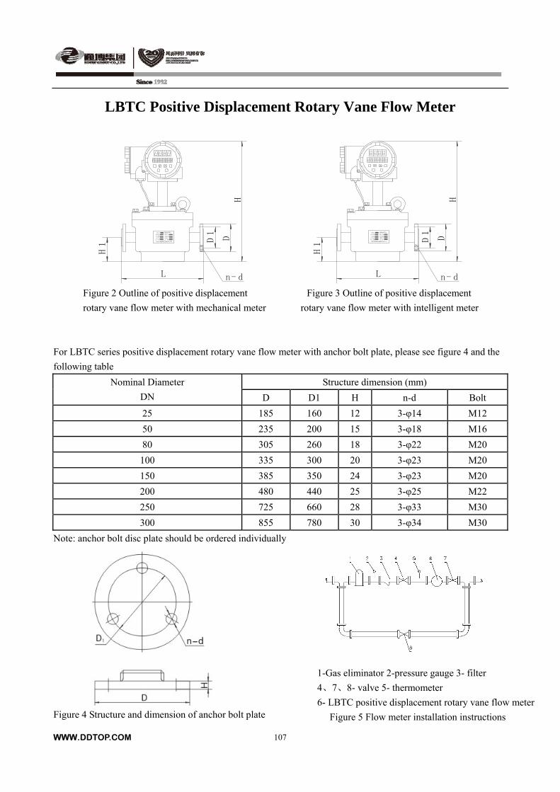
LBTC Positive Displacement Rotary Vane Flow Meter
LBTC 刮板流量计
公称通径
工作温度
工作压力
出厂日期
丹东市通博电器有限公司
精度等级
防爆标志
防爆证号
出厂编号
H1
H
D1
D
L n- d
LB TC 刮板流量计
公称通径
工作温度
工作压力
出厂日期
丹东市通博电器有限公司
精度等级
防爆标志
防爆证号
出厂编号
H1
H
D1
D
L n- d Figure 2 Outline of positive displacement Figure 3 Outline of positive displacement
rotary vane flow meter with mechanical meter rotary vane flow meter with intelligent meter
For LBTC series positive displacement rotary vane flow meter with anchor bolt plate, please see figure 4 and the
following table
Structure dimension (mm) Nominal Diameter
DN D D1 H n-d Bolt
25 185 160 12 3-φ14 M12
50 235 200 15 3-φ18 M16
80 305 260 18 3-φ22 M20
100 335 300 20 3-φ23 M20
150 385 350 24 3-φ23 M20
200 480 440 25 3-φ25 M22
250 725 660 28 3-φ33 M30
300 855 780 30 3-φ34 M30
Note: anchor bolt disc plate should be ordered individually
1-Gas eliminator 2-pressure gauge 3- filter
4、7、8- valve 5- thermometer
6- LBTC positive displacement rotary vane flow meter
Figure 5 Flow meter installation instructions
Figure 4 Structure and dimension of anchor bolt plate
WWW.DDTOP.COM
107
WWW.DDTOP.COM
108
LBTC Positive Displacement Rotary Vane Flow Meter
2. Installation requirements We suggest LBTC positive displacement rotary vane flow meter should install according to installation instruction
as shown in figure 5.
2.1 Connection pipe of LBTC positive displacement rotary vane flow meter should be the same diameter and axis
as inlet and exit of flow meter, can not have projections on pipe wall. Connection pipe near flow meter can’t
have obvious transformation, and minimizing the impact on flow meter due to expansion and contraction of
pipeline.
2.2 Installing flow meter on new pipe, to avoid sundries in pipe along with the fluid entering into flow meter that
will cause damage, you can use short pipe instead of flow meter. After cleaning or purging the pipe, install the
flow meter. Don’t let scavenging air pass bulk.
2.3 You should take off the sealing-capping of connecting flange on flow meter before installation, if impurity and
gas content in fluid is high, we suggest installing filter、gas eliminator or LPXG before flow meter, filter mesh
should be used as following ranges: flow meter of DN20-50 should use 20mesh, DN80-150 should use
15mesh, DN200-300 should use 10mesh.
2.4 The flow meter should be installed horizontally on main pipe ,generally the slant angle should be no more than
15°,to make sure clearance of rotary vane of flow meter is equalizing and measurement is accurate.
2.5 Direction of arrow on flow meter should be the same as flow direction of fluid when installing, flow meter and
straight pipe of both sides should be on coaxial line.
2.6 Flow throttle valve and switch valve installed on pipe work reliably. For observation and inspection
conveniently, abscission of bypass pipe can use closing device which is composed of two switch valves in
series, there is a small-bore leak valve on the short connecting pipe between two valves, you can inspect the
cutting capacity conveniently.
2.7 Use strictly according to range on the nameplate of flow meter: all of max. flow, operating pressure, operating
temperature, fluid viscosity can’t exceed specialized range on the nameplate of flow meter.
2.8 When using the flow meter, you should open the valve slowly and increase the flow gradually until reaching
needed flow, but can’t exceed the max. flow limited by nameplate on flow meter.
2.9 The flow meter should be maintained periodically, main content of maintenance as follows:
a) Inspecting whether the flow range exceeds max. flow on the nameplate;
b) Observing whether there is regular noise in the housing of operating flow meter, and whether there is bigger
impurity and foreign matter entering flow meter.
c) After the parts replacement, you need to re-calibrate.
d) The flow meter in normally using should be calibrated regularly according to industry stipulation.
e) When using mechanical integrating instrument, you should inject lubricant regularly.
Order requirements
Specification:
Accuracy class:
Max. Min. flow value;
Fluid:
Operating temperature:
Fluid viscosity
Please note if the transmission distance is
more than 100m;
Brand of material contacting fluid:
Other flanges standard:

LZZ –S DOUBLE ROTOR FLOWMETER
Summary
LZZ –S Double Rotor Flowmeter is high precision measuring instruments used for continuous measurement of liquid flow in pipeline. It has no pulse, low noise, high precision, high reliability, wide range, small pressure loss, strong adaptability of viscosity, and can measure the high temperature, high viscosity liquids, calibration of convenient, easy to install, and many other advantages. The meter is equipped with the pointer display, word wheel cumulative counting device, and can directly display cumulative flow when liquid flows through the pipe, it can also realize remote display through connection between the transmitter and the electronic instrument or computer. The flowmeter is suitable for petrochemical, chemical, chemical fiber, traffic, commerce, food, medicine, health care and other industrial departments of commerce measurement control and engineering management.
Principle of Operating
LZZ -S double rotor flowmeter consists of flow transmitter and counter. The main part of the transmitter is composed of measuring room equipped with a pair of special tooth profile of helical rotor and seal coupling. Counting mechanism contains retarding mechanism, precision adjusting mechanism, counter for print wheel accumulation and electrical transmitter, etc.
Measuring room mainly composed of a pair of special rotor and cover seal cavity as flow measurement units. Rotor powered by the differential pressure of import and export of flowmeter so that send the inlet liquid to the exit after passing the sealing cavity measurement. The amount of liquid through seal chamber every turn is eight times of the picture, sealing coupling transfers the total rotation of the rotor and rotating speed to the counting mechanism, and a pointer to display and print wheel accumulation, then you can know the total amount of liquid passing by the pipe. You can also install transmitter in counting mechanism, namely become the flowmeter which can output signal, the transmitter matches with our company’s electric display instrument, can also realize remote transmission (quantitative, accumulated, moments, etc) automatic measurement and control. You can see the instruction in the display instrument classification.
1. counter 2. transmitter 3. precision adjusting mechanism
4. flow transmitter 5.external precision adjustment device
WWW.DDTOP.COM
109
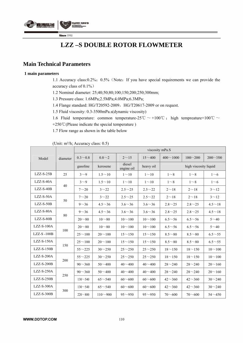
WWW.DDTOP.COM
110
LZZ –S DOUBLE ROTOR FLOWMETER
Main Technical Parameters
1 main parameters
1.1 Accuracy class:0.2%;0.5%(Note:If you have special requirements we can provide the
accuracy class of 0.1%)
1.2 Nominal diameter: 25;40;50;80;100;150;200;250;300mm;
1.3 Pressure class: 1.6MPa;2.5MPa;4.0MPa;6.3MPa;
1.4 Flange standard: HG/T20592-2009,HG/T20617-2009 or on request.
1.5 Fluid viscosity: 0.3-3500mPa.s(dynamic viscosity)
1.6 Fluid temperature: common temperature-25~ +100; high tempreature+100~
+250(Please indicate the special temperature )
1.7 Flow range as shown in the table below
(Unit: m³/h; Accuracy class: 0.5)
viscosity mPa.S
0.3~0.8 0.8~2 2~15 15~400 400~1000 1000~2000 2000~3500 Model diameter
gasoline kerosene diesel
engine oilheavy oil high viscosity liquid
LZZ-S-25B 25 3~9 1.5~10 1~10 1~10 1~8 1~8 1~6
LZZ-S-40A 3~9 1.5~10 1~10 1~10 1~8 1~8 1~6
LZZ-S-40B 40
7~20 3~22 2.5~25 2.5~22 2~18 2~18 3~12
LZZ-S-50A 7~20 3~22 2.5~25 2.5~22 2~18 2~18 3~12
LZZ-S-50B 50
9~36 4.5~36 3.6~36 3.6~36 2.8~25 2.8~25 4.5~18
LZZ-S-80A 9~36 4.5~36 3.6~36 3.6~36 2.8~25 2.8~25 4.5~18
LZZ-S-80B 80
20~80 10~80 10~100 10~100 6.5~56 6.5~56 5~40
LZZ-S-100A 20~80 10~80 10~100 10~100 6.5~56 6.5~56 5~40
LZZ-S -100B 100
25~100 20~100 15~150 15~150 8.5~80 8.5~80 6.5~55
LZZ-S-150A 25~100 20~100 15~150 15~150 8.5~80 8.5~80 6.5~55
LZZ-S-150B 150
55~225 30~250 25~250 25~250 18~150 18~150 10~100
LZZ-S-200A 55~225 30~250 25~250 25~250 18~150 18~150 10~100
LZZ-S-200B 200
90~360 50~400 40~400 40~400 28~240 28~240 20~160
LZZ-S-250A 90~360 50~400 40~400 40~400 28~240 28~240 20~160
LZZ-S-250B 250
130~540 65~540 60~600 60~600 42~360 42~360 30~240
LZZ-S-300A 130~540 65~540 60~600 60~600 42~360 42~360 30~240
LZZ-S-300B 300
220~800 110~900 95~950 95~950 70~600 70~600 54~450

WWW.DDTOP.COM
111
LZZ –S DOUBLE ROTOR FLOWMETER
(Unit: m³/h; Accuracy class:0.2)
viscosity mPa.S
0.3~0.8 0.8~2 2~15 15~400 400~1000 1000~2000 2000~3500 Model diameter
gasoline kerosene diesel
engine oilheavy oil high viscosity liquid
LZZ-S-25B 25 3.5~8 3~10 2~10 2~10 2~8 2~8 2~6 LZZ-S-40A 3.5~8 3~10 2~10 2~10 2~8 2~8 2~6
LZZ-S-40B 40
8~20 5.5~22 4.5~22 4.5~22 4~18 4~18 3~12 LZZ-S-50A 8~20 5.5~22 4.5~22 4.5~22 4~18 4~18 3~12 LZZ-S-50B
50 15~36 9~36 7~36 7~36 6~25 6~25 4.5~18
LZZ-S-80A 15~36 9~36 7~36 7~36 6~25 6~25 4.5~18 LZZ-S-80B
80 30~80 20~80 15~80 15~80 14~56 14~56 10~40
LZZ-S-100A 30~80 20~80 15~80 15~80 14~56 14~56 10~40 LZZ-S-100B
100 40~100 25~100 20~120 20~120 18~72 18~70 14~55
LZZ-S-150A 40~100 25~100 20~120 20~120 18~72 18~70 14~55 LZZ-S-150B
150 88~220 58~225 44~220 44~220 38~150 38~150 25~100
LZZ-S-200A 88~220 58~225 44~220 44~220 38~150 38~150 25~100 LZZ-S-200B
200 150~360 90~360 72~360 72~360 50~210 50~210 40~160
LZZ-S-250A 150~360 90~360 72~360 72~360 50~210 50~210 40~160 LZZ-S-250B
250 180~540 135~540 100~540 100~540 90~360 90~360 60~240
LZZ-S-300A 180~540 135~540 100~540 100~540 90~360 90~360 60~240 LZZ-S-300B
300 250~800 220~900 180~900 180~900 150~600 150~600 110~450
2The major component material and the nominal pressure
Model Housing , front and
back cover
covering plate
Rotor Axis Axle sleeve Nominal pressure(MPa)
LZZ-S-C Carbon steel Carbon
steel Stainless
Steel Graphite Below DN100 is 4.0;Beyond
DN150 is 2.5
LZZ-S-P Stainless
Steel Stainless
Steel
cast iron 、aluminium alloy,Stainless Steel
Stainless Steel
Graphite / ball bearing
1.6、2.0、2.5、
LZZ-S-S double housing
Specification:DN80、DN100、DN150 Nominal pressure 6.3NPa;DN200 Nominal pressure 4.0MPa;
3 Double rotor flowmeter with warm jacket In order to facilitate transporting and measuring flow for the medium that is easy to freeze under normal temperature or condense, crystallize, usually need to heat medium in the system pipe, and melt the medium and hold its temperature. But due to the double rotor flowmeter installation does not allow directly access to the steam (purpose is to prevent damage meter), therefore we design the flowmeter with warm jacket. The flowmeter housing add warm jacket outside, to melt solidified medium in the flowmeter, you can use hot water, hot oil or below 200 steam flux into the warm jacket and keep certain temperature so that make sure the flowmeter keep moving. The filter installed on double rotor flowmeter can also be adopted with the structure of warm jacket. The inlet and outlet of warm jacket usually is designed by DN15 diameter flange, or on special request. The warm jacket nominal pressure is 0.5Mpa, or on special request.
LZZ –S DOUBLE ROTOR FLOWMETER
Model Selection Table
Model Code Content
LZZ-S Double rotor flowmeter
25 Nominal Diameter:DN25mm
40 Nominal Diameter:DN40mm
50 Nominal Diameter:DN50mm
80 Nominal Diameter:DN80mm
100 Nominal Diameter:DN100mm
150 Nominal Diameter:DN150mm
200 Nominal Diameter:DN200mm
250 Nominal Diameter:DN250mm
300 Nominal Diameter:DN300mm
C The structure of material:Carbon Steel
P The structure of material:Stainless Steel
1.6 Nominal Pressure PN1.6MPa
2.5 Nominal Pressure PN2.5MPa
4.0 Nominal Pressure PN4.0MPa
6.3 Nominal Pressure PN6.3MPa
JS Counter:local indication;
GF With transmitter,output signal:pulse;
MF With transmitter,output signal:4~20mA;
i Explosion protection type:Intrinsically safe ExiaIICT5
d Explosion protection type:Explosion isolation ExdIICT6
C Normal temperature
G High temperature
D Single housing
S Double housing
B Warm jacket
Outline and installation dimension
1 The structure and dimension
1.1 The structure and dimension of the flowmeter
WWW.DDTOP.COM
112
L Model diameter standard Double
housing H B C I D D1 N d0 Pressure MPa
Reference weight
LZZ-S-25B 25 300 420 175 228 90 115 85 4 4 29 LZZ-S-40A 300 420 175 228 90 150 110 4 4 33 LZZ-S-40B
40 300 450 200 258 112 150 110 4 4 40
LZZ-S-50A 300 450 200 258 112 165 125 4 4 42 LZZ-S-50B
50 340 525 240 333 150 165 125 4 4 62
LZZ-S-80A 340 525 240 333 150 200 160 8 8 64 LZZ-S-80B
80 380 400 580 285 388 175 200 160 8 8 94
LZZ-S-100A 380 400 580 285 388 175 235 190 8 8 98 LZZ-S-100B
100 440 450 660 339 468 250 235 190 8 8 146
LZZ-S-150A 440 450 660 339 468 250 300 250 8 8 152 LZZ-S-150B
150 500 560 740 410 548 270 300 250 8 8 238
LZZ-S-200A 500 560 740 410 548 270 360 310 12 12
The flange example:4.0MPa
245 LZZ-S-200B
200 550 700 820 455 628 285 360 310 12 12 337
LZZ-S-250A 550 700 820 455 628 285 425 370 12 12 350 LZZ-S-250B
250 700 910 550 718 350 425 370 12 12 570
LZZ-S-300A 700 910 550 718 350 485 430 16 16 600 LZZ-S-300B
300 800 1010 645 818 415 485 430 16 16
The flange example :2.5MPa
855
Note: (1) "H"dimension prepare for G the dimension of the governor;
(2) The flowmeter with warm jacket, the inlet and outlet of heat source is DN15 flange
connection;
(3) If flowmeter configures heat radiator, please add the heat radiator size to H size in the
table, it is total height of high temperature flowmeter;
(4)Double housing flowmeter pressure can be up to 6.3 MPa; DN200 pressure is 4.0 MPa.
Special designment can be up to 10 MPa;
1.2The radiator structure and dimension
Note:
If the model of the flowmeter is G, the flowmeter is high temperature, it is used for 60-120,
without transmitter and may not configure heat radiator.
If the model of the flowmeter is G2, the flowmeter is high temperature, it is used for
120-250 , and configure long heat radiator.
If the model of the flowmeter is G1, the flowmeter is high temperature, it is used for
60-120, and with transmitter, configuring short heat radiator.
2 Installation and application
2.1 The filter should be installed in front of the flowmeter, their housing’s arrow directions are
the same.
2.2 When the measured liquid containing gas, the gas separator should be installed in front of
WWW.DDTOP.COM
113
flowmeter.
2.3 Under the condition of correct installation of the flow meter, if it is not easy to see reading,
counter can be turned to 180 ° or 90 °.
2.4 Push the rotor a few times with a wooden stick from the exit before installing a new
flowmeter, if the rotor does not move, you can soak with gasoline (to avoid deposits after factory
check).
2.5 Throttle valve should be installed in the inlet of the flow meter, on-off valve installed in the
exit, When using on-off valve needs a slow start, don't suddenly open valve.
2.6 It is forbidden to use steam sweep line through the flowmeter.
2.7 In continuous occasion, flowmeter must add by-pass pipe.
2.8 The pipe shall be flush before flowmeter installation, when flushing straight pipe (replace
flow meter location) to prevent welding slag, debris into the meter.
2.9 It is forbidden to check meter composed of carbon steel material by water.
2.10 When flow meter measuring flow, the value of flow shall not exceed the range of flow
range. Flow meter working in 40-80% of maximum flow is suitable.
3 Error calculation and adjustment
3.1 The basic error of flowmeter is calculated by the verification flow point of all measured
values according to the following formula: (volume)
E=(Vm-V)/V×100%
E--The error of flowmeter(generally refers to accumulative error) take two significant figures.
WWW.DDTOP.COM
114
Vm--Flowmeter measuring values(indicating value)
V--After meter is corrected, flow standard device measuring value ( the actual value)
From the basic formula of error, when Vm is greater than V, The basic error of flowmeter
is“+”, it indicates flowmeter going fast.
From the basic formula of error, when Vm is less than V, The basic error of flowmeter is“-”, it
indicates flowmeter going slow.
In order to make the flowmeter errors within a basic error limits, often need to adjust the error.
By replacing a pair of adjusting gear (tooth) in counter changes the mechanical transmission
speed ratio, so that the flow meter’s indicating value gets adjusted.
Error adjustment can't change features of the flowmeter, only make its features curve
artificially in a new coordinate. In general, in the prescribed (or actual use) flow range, the basic
error range of the maximum and minimum flow check point is not more than the precision of the
basic error limits, all can realize flowmeter basic error qualified by adjusting error.
For flow meter has been used, usually use the original adjusting gear checking error, and then
adjusting error according to the error of the specific situation.
3.2 Double rotor flowmeter error adjusting method (error adjustment instructions)
3.2.1 Common error adjusting method:
3.2.1.1 In designing the standard of the double gear is 38/35, During inspection, if you find the
meter is going faster, namely appear error (+),such as +1.02-+0.3,the gear should be changed
38/35 into 41/38, at this time original point of the error curve moves up from 38/35 gear
corresponding to zero to 41/38 gear to the location of + 0.63 (see table), so error curve in a new
coordinate, and the error of flowmeter has been adjusted in the range of + 0.39 ~ ﹣0.33,and
satisfy the qualified requirements(see figure 1).
3.2.1.2When the flowmeter is working, due to the
different working conditions and changes, the error
usually changes and it may exceed the maximium error,
if only the error range is less than 1%, generally can be
transferred to qualified, for example, instrument error
drops to 0.7 ~ + 0.2, and need to change the double
gear, at first you should know that how many gear
teeth the double gear has. If the double gear is38/35,
adjust according to the above of the first method. If the
double gear is38/35, then take the error+ 0.63
corresponding to gear as zero(the origin of
coordinates).Now the 41/38 gear should be changed
into the double gear of 41/37, error can be adjusted to
the range of﹣0.5-﹢0.4 that make sure qualified (see figure 2).
3.2.1.3 The specific method of calibrating and adjusting double rotor flowmeter of class 0.2
should be according to the national metrological verification procedures JJG667-1997 "liquid
volumetric flowmeter verification regulation".
3.2.2 The error adjustment method of GF3 external precision regulator
GF3 is a kind of external precision regulator, when error adjusting, do not need to remove the
governor and can be directly adjusted in the external, the operation is convenient, easy and
WWW.DDTOP.COM
115
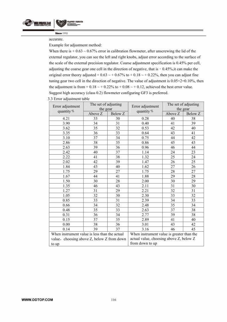
WWW.DDTOP.COM
116
accurate.
Example for adjustment method:
When there is + 0.63 ~ 0.67% error in calibration flowmeter, after unscrewing the lid of the
external regulator, you can see the left and right knobs, adjust error according to the surface of
the scale of the external precision regulator. Coarse adjustment specification is 0.45% per cell,
adjusting the coarse gear one cell in the direction of negative, that is﹣0.45%,it can make the
original error theory adjusted + 0.63 ~ + 0.67% to + 0.18 ~ + 0.22%, then you can adjust fine
tuning gear two cell in the direction of negative. The value of adjustment is 0.05×2=0.10%, then
the adjustment is from + 0.18 ~ + 0.22% to + 0.08 ~ + 0.12, achieved the best error value.
Suggest high accuracy (class 0.2) flowmeter configuring GF3 is preferred.
3.3 Error adjustment table The set of adjusting
the gear The set of adjusting
the gear Error adjustment
quantity﹪ Above Z Below Z
Error adjustment quantity﹪
Above Z Below Z 4.21 33 30 0.28 40 38 3.90 34 31 0.40 41 39 3.62 35 32 0.53 42 40 3.35 36 33 0.64 43 41 3.10 37 34 0.75 44 42 2.86 38 35 0.86 45 43 2.63 39 36 0.96 46 44 2.42 40 37 1.14 24 23 2.22 41 38 1.32 25 24 2.02 42 39 1.47 26 25 1.84 43 40 1.62 27 26 1.75 29 27 1.75 28 27 1.67 44 41 1.88 29 28 1.50 30 28 2.00 30 29 1.35 46 43 2.11 31 30 1.27 31 29 2.21 32 31 1.05 32 30 2.30 33 32 0.85 33 31 2.39 34 33 0.66 34 32 2.48 35 34 0.48 35 33 2.63 37 38 0.31 36 34 2.77 39 38 0.15 37 35 2.89 41 40 0.00 38 36 3.01 43 42 0.14 39 37 3.16 46 45
When instrument value is less than the actual value,choosing above Z, below Z from down to up
When instrument value is greater than the actual value, choosing above Z, below Z from down to up
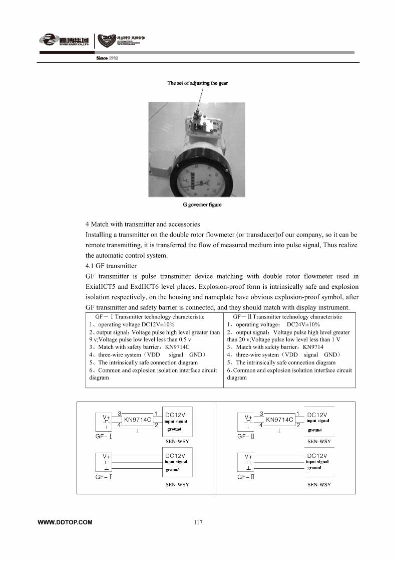
4 Match with transmitter and accessories
Installing a transmitter on the double rotor flowmeter (or transducer)of our company, so it can be
remote transmitting, it is transferred the flow of measured medium into pulse signal, Thus realize
the automatic control system.
4.1 GF transmitter
GF transmitter is pulse transmitter device matching with double rotor flowmeter used in
ExiaIICT5 and ExdIICT6 level places. Explosion-proof form is intrinsically safe and explosion
isolation respectively, on the housing and nameplate have obvious explosion-proof symbol, after
GF transmitter and safety barrier is connected, and they should match with display instrument. GF-ⅠTransmitter technology characteristic 1、operating voltage DC12V±10% 2、output signal:Voltage pulse high level greater than 9 v;Voltage pulse low level less than 0.5 v 3、Match with safety barrier:KN9714C 4、three-wire system(VDD signal GND) 5、The intrinsically safe connection diagram 6、Common and explosion isolation interface circuit diagram
GF-ⅡTransmitter technology characteristic 1、operating voltage: DC24V±10% 2、output signal:Voltage pulse high level greater than 20 v;Voltage pulse low level less than 1 V 3、Match with safety barrier:KN9714 4、three-wire system(VDD signal GND) 5、The intrinsically safe connection diagram 6、Common and explosion isolation interface circuit diagram
WWW.DDTOP.COM
117
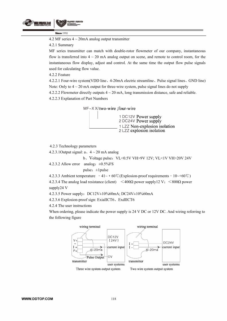
4.2 MF series 4 ~ 20mA analog output transmitter
4.2.1 Summary
MF series transmitter can match with double-rotor flowmeter of our company, instantaneous
flow is transferred into 4 ~ 20 mA analog output on scene, and remote to control room, for the
instantaneous flow display, adjust and control. At the same time the output flow pulse signals
used for calculating flow value.
4.2.2 Feature
4.2.2.1 Four-wire system(VDD line、4-20mA electric streamline、Pulse signal lines、GND line)
Note: Only to 4 ~ 20 mA output for three-wire system, pulse signal lines do not supply
4.2.2.2 Flowmeter directly outputs 4 ~ 20 mA, long transmission distance, safe and reliable.
4.2.2.3 Explanation of Part Numbers
4.2.3 Technology parameters
4.2.3.1Output signal: a、4 ~ 20 mA analog
b、Voltage pulse:VL<0.5V VH>9V 12V; VL<1V VH>20V 24V
4.2.3.2 Allow error analog:±0.5%FS
pulse:±1pulse
4.2.3.3 Ambient temperature ﹣41~﹢60 (Explosion -proof requirements﹣10~+60)
4.2.3.4 The analog load resistance (client) <400Ω power supply12 V;<800Ω power
supply24 V
4.2.3.5 Power supply:DC12V±10%60mA; DC24V±10%60mA
4.2.3.6 Explosion-proof sign: ExiaIICT6、ExdIICT6
4.2.4 The user instructions
When ordering, please indicate the power supply is 24 V DC or 12V DC. And wiring referring to
the following figure
WWW.DDTOP.COM
118
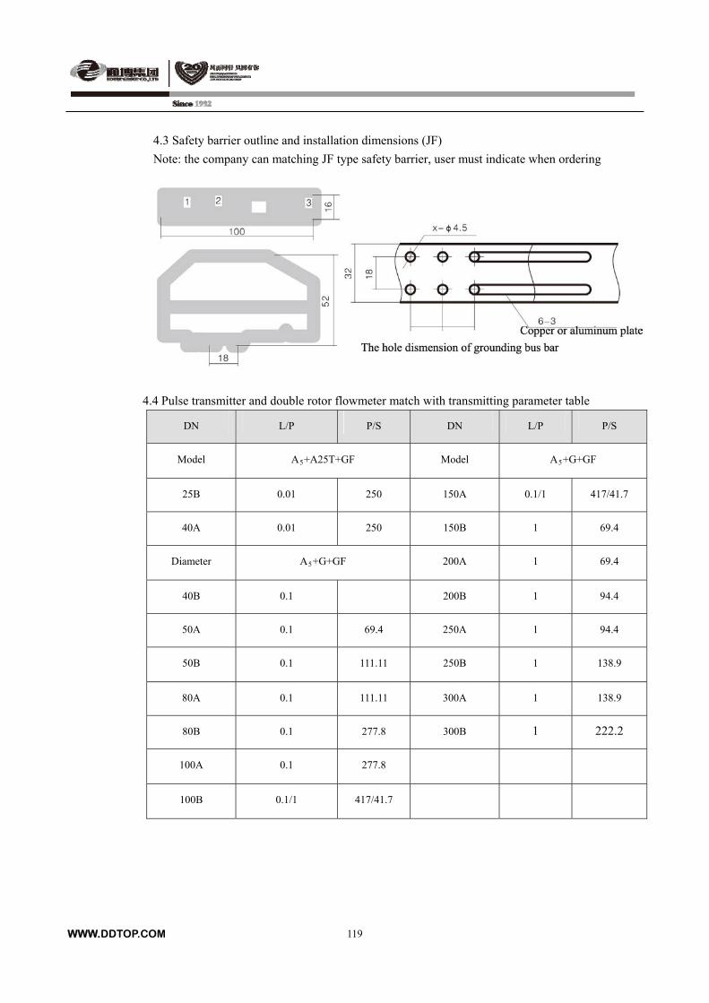
4.3 Safety barrier outline and installation dimensions (JF)
Note: the company can matching JF type safety barrier, user must indicate when ordering
4.4 Pulse transmitter and double rotor flowmeter match with transmitting parameter table
DN L/P P/S DN L/P P/S
Model A5+A25T+GF Model A5+G+GF
25B 0.01 250 150A 0.1/1 417/41.7
40A 0.01 250 150B 1 69.4
Diameter A5+G+GF 200A 1 69.4
40B 0.1 200B 1 94.4
50A 0.1 69.4 250A 1 94.4
50B 0.1 111.11 250B 1 138.9
80A 0.1 111.11 300A 1 138.9
80B 0.1 277.8 300B 1 222.2
100A 0.1 277.8
100B 0.1/1 417/41.7
WWW.DDTOP.COM
119
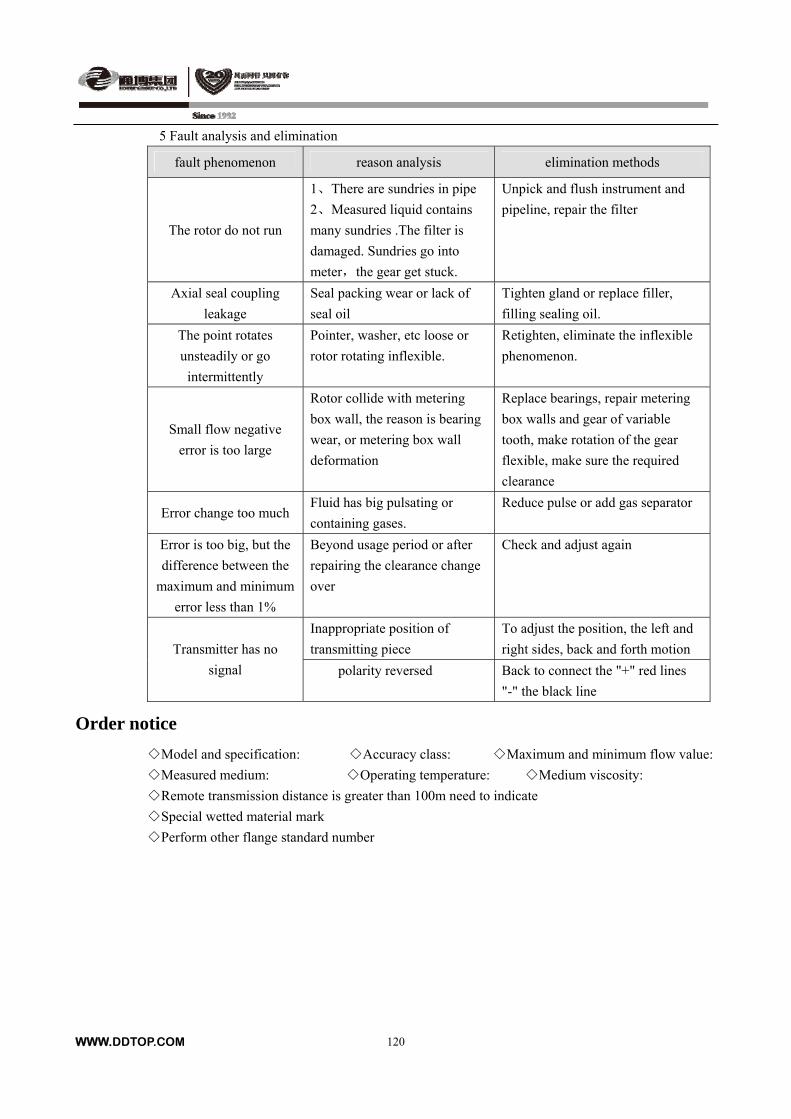
WWW.DDTOP.COM
120
5 Fault analysis and elimination
fault phenomenon reason analysis elimination methods
The rotor do not run
1、There are sundries in pipe
2、Measured liquid contains
many sundries .The filter is
damaged. Sundries go into
meter,the gear get stuck.
Unpick and flush instrument and
pipeline, repair the filter
Axial seal coupling
leakage
Seal packing wear or lack of
seal oil
Tighten gland or replace filler,
filling sealing oil.
The point rotates
unsteadily or go
intermittently
Pointer, washer, etc loose or
rotor rotating inflexible.
Retighten, eliminate the inflexible
phenomenon.
Small flow negative
error is too large
Rotor collide with metering
box wall, the reason is bearing
wear, or metering box wall
deformation
Replace bearings, repair metering
box walls and gear of variable
tooth, make rotation of the gear
flexible, make sure the required
clearance
Error change too much Fluid has big pulsating or
containing gases.
Reduce pulse or add gas separator
Error is too big, but the
difference between the
maximum and minimum
error less than 1%
Beyond usage period or after
repairing the clearance change
over
Check and adjust again
Inappropriate position of
transmitting piece
To adjust the position, the left and
right sides, back and forth motion Transmitter has no
signal polarity reversed Back to connect the "+" red lines
"-" the black line
Order notice
Model and specification: Accuracy class: Maximum and minimum flow value:
Measured medium: Operating temperature: Medium viscosity:
Remote transmission distance is greater than 100m need to indicate
Special wetted material mark
Perform other flange standard number
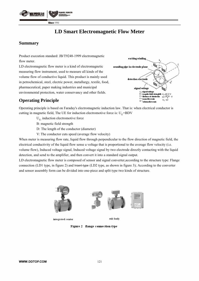
LD Smart Electromagnetic Flow Meter
Summary
Product execution standard: JB/T9248-1999 electromagnetic
flow meter.
LD electromagnetic flow meter is a kind of electromagnetic
measuring flow instrument, used to measure all kinds of the
volume flow of conductive liquid. This product is mainly used
in petrochemical, steel, electric power, metallurgy, textile, food,
pharmaceutical, paper making industries and municipal
environmental protection, water conservancy and other fields.
Operating Principle
Operating principle is based on Faraday's electromagnetic induction law. That is: when electrical conductor is
cutting in magnetic field, The UE for induction electromotive force is: UE=BDV
UE: induction electromotive force
B: magnetic field strength
D: The length of the conductor (diameter)
V: The conductor cuts speed (average flow velocity)
When meter is measuring flow rate, liquid flow through perpendicular to the flow direction of magnetic field, the
electrical conductivity of the liquid flow sense a voltage that is proportional to the average flow velocity (i.e.
volume flow), Induced voltage signal, Induced voltage signal by two electrode directly contacting with the liquid
detection, and send to the amplifier, and then convert it into a standard signal output.
LD electromagnetic flow meter is composed of sensor and signal converter,according to the structure type: Flange
connection (LD1 type, in figure 2) and Insert-type (LD2 type, as shown in figure 3); According to the converter
and sensor assembly form can be divided into one-piece and split type two kinds of structure.
WWW.DDTOP.COM
121
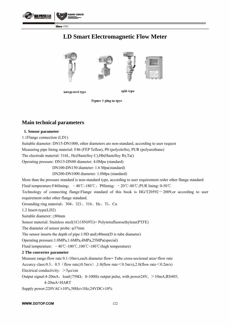
LD Smart Electromagnetic Flow Meter
Main technical parameters
1. Sensor parameter
1.1Flange connection (LD1)
Suitable diameter: DN15-DN1000, other diameters are non-standard, according to user request
Measuring pipe lining material: F46 (FEP Teflon), P0 (polyolefin), PUR (polyurethane)
The electrode material: 316L, Hc(Hastelloy C),Hb(Hastelloy B),Ta()
Operating pressure: DN15-DN80 diameter: 4.0Mpa (standard)
DN100-DN150 diameter: 1.6 Mpa(standard)
DN200-DN1000 diameter: 1.0Mpa (standard)
More than the pressure standard is non-standard type, according to user requirement order other flange standard
Fluid temperature:F46lining:﹣40-180,P0lining: ﹣20-80 ;PUR lining : 0-50
Technology of connecting flange:Flange standard of this book is HG/T20592-2009,or according to user
requirement order other flange standard.
Grounding ring material:304、321、316、Hc、Ti、Cu
1.2 Insert-type(LD2)
Suitable diameter: ≥80mm
Sensor material: Stainless steel(1Cr18Ni9Ti)+ Polytetrafluoroethylene(PTFE)
The diameter of sensor probe: φ37mm
The sensor inserts the depth of pipe:1/8D and≤40mm(D is tube diameter)
Operating pressure:1.0MPa,1.6MPa,4MPa,25MPa(special)
Fluid temperature: ﹣40-100 ,100 -180 (high temperature)
2 The converter parameter
Measure range:flow rate 0.1-10m/s,each diameter flow= Tube cross-sectional area×flow rate
Accurcy class:0.3、0.5(flow rate≥0.5m/s),1.0(flow rate<0.5m/s),2.0(flow rate<0.2m/s)
Electrical conductivity: >5µs/cm
Output signal:4-20mA,load≤750Ω;0-100Hz output pulse, with power24V, >10mA;RS485;
4-20mA+HART
Supply power:220VAC±10%,50Hz±1Hz;24VDC±10%
WWW.DDTOP.COM
122
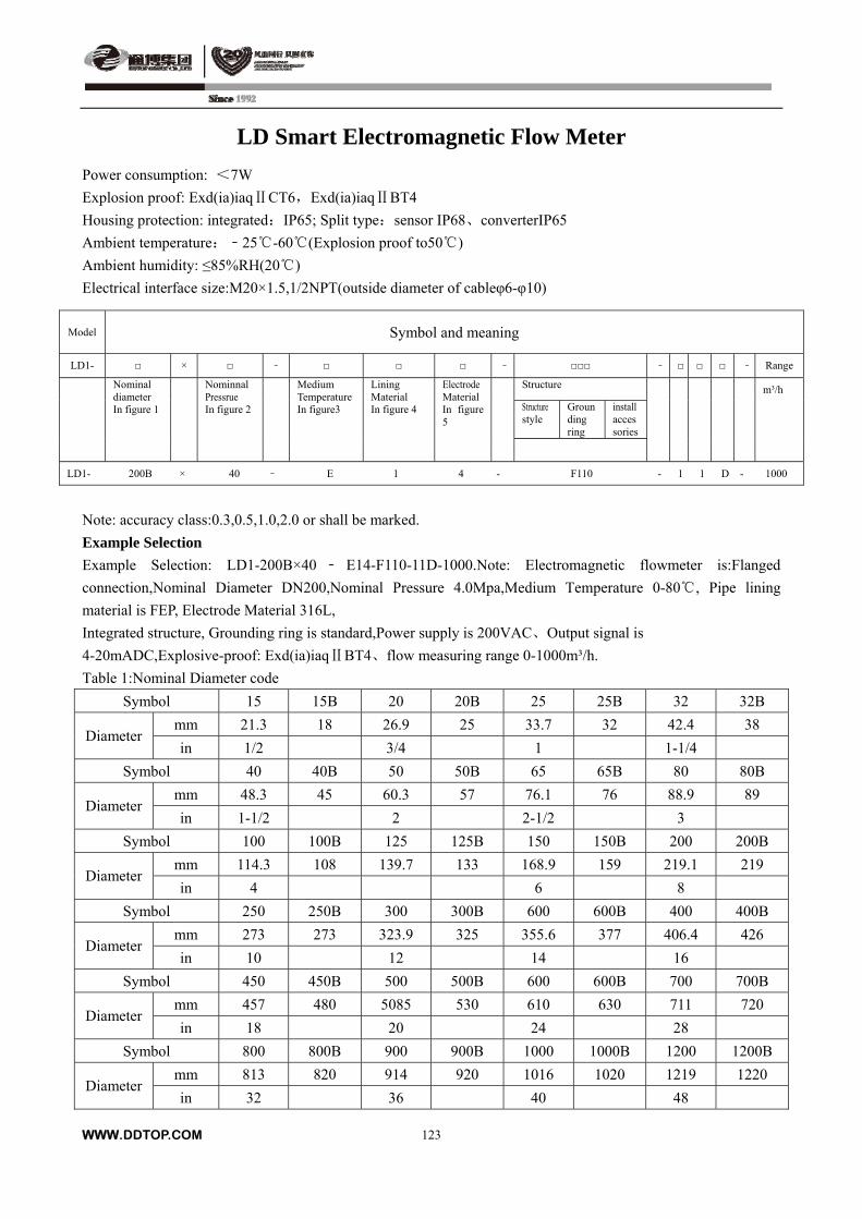
LD Smart Electromagnetic Flow Meter
Power consumption: <7W
Explosion proof: Exd(ia)iaq CT6Ⅱ ,Exd(ia)iaq BT4Ⅱ
Housing protection: integrated:IP65; Split type:sensor IP68、converterIP65
Ambient temperature:﹣25-60 ( Explosion proof to50)
Ambient humidity: ≤85%RH(20 )
Electrical interface size:M20×1.5,1/2NPT(outside diameter of cableφ6-φ10)
Model Symbol and meaning
LD1- × ﹣ ﹣ ﹣ ﹣ Range
Structure
Structure style
Grounding ring
install accessories
Nominal diameter In figure 1
Nominnal Pressrue In figure 2
Medium Temperature In figure3
Lining Material In figure 4
Electrode Material In figure 5
m³/h
LD1- 200B × 40 ﹣ E 1 4 - F110 - 1 1 D - 1000
Note: accuracy class:0.3,0.5,1.0,2.0 or shall be marked.
Example Selection
Example Selection: LD1-200B×40 ﹣ E14-F110-11D-1000.Note: Electromagnetic flowmeter is:Flanged
connection,Nominal Diameter DN200,Nominal Pressure 4.0Mpa,Medium Temperature 0-80 , Pipe lining
material is FEP, Electrode Material 316L,
Integrated structure, Grounding ring is standard,Power supply is 200VAC、Output signal is
4-20mADC,Explosive-proof: Exd(ia)iaq BT4Ⅱ 、flow measuring range 0-1000m³/h.
Table 1:Nominal Diameter code
Symbol 15 15B 20 20B 25 25B 32 32B
mm 21.3 18 26.9 25 33.7 32 42.4 38 Diameter
in 1/2 3/4 1 1-1/4
Symbol 40 40B 50 50B 65 65B 80 80B
mm 48.3 45 60.3 57 76.1 76 88.9 89 Diameter
in 1-1/2 2 2-1/2 3
Symbol 100 100B 125 125B 150 150B 200 200B
mm 114.3 108 139.7 133 168.9 159 219.1 219 Diameter
in 4 6 8
Symbol 250 250B 300 300B 600 600B 400 400B
mm 273 273 323.9 325 355.6 377 406.4 426 Diameter
in 10 12 14 16
Symbol 450 450B 500 500B 600 600B 700 700B
mm 457 480 5085 530 610 630 711 720 Diameter
in 18 20 24 28
Symbol 800 800B 900 900B 1000 1000B 1200 1200B
mm 813 820 914 920 1016 1020 1219 1220 Diameter
in 32 36 40 48
WWW.DDTOP.COM
123
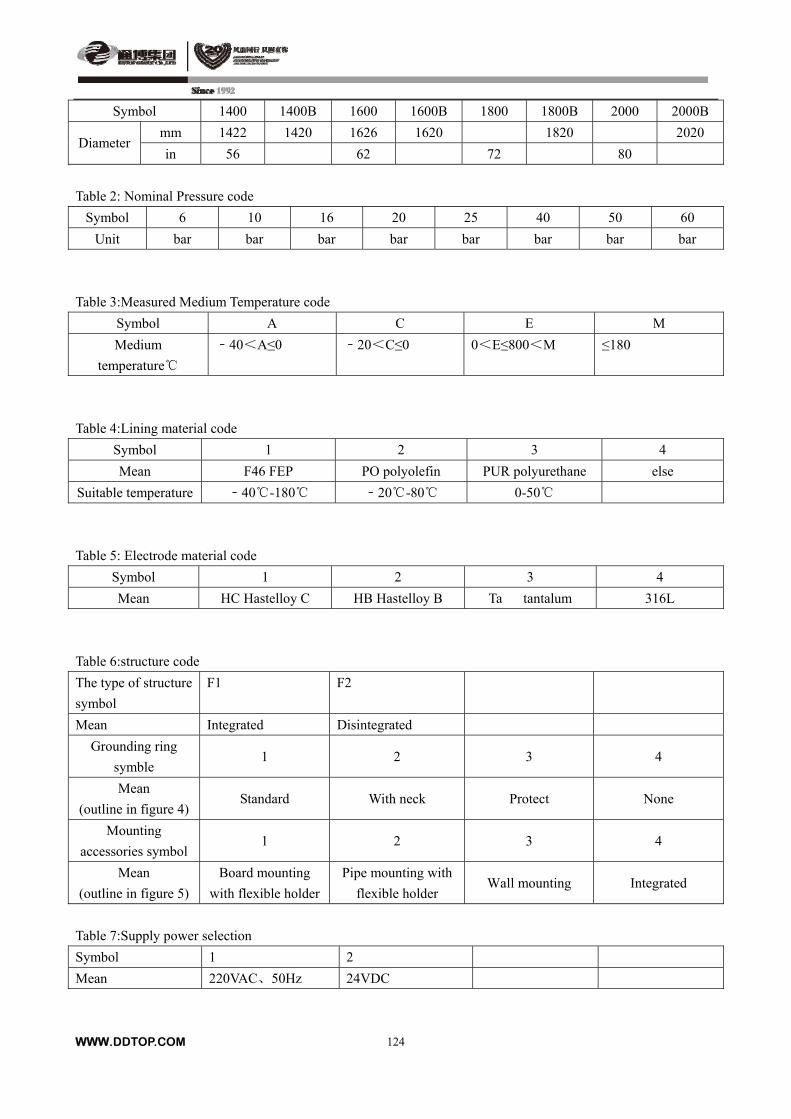
WWW.DDTOP.COM
124
Symbol 1400 1400B 1600 1600B 1800 1800B 2000 2000B
mm 1422 1420 1626 1620 1820 2020 Diameter
in 56 62 72 80
Table 2: Nominal Pressure code
Symbol 6 10 16 20 25 40 50 60
Unit bar bar bar bar bar bar bar bar
Table 3:Measured Medium Temperature code
Symbol A C E M
Medium
temperature
﹣40<A≤0 ﹣20<C≤0 0<E≤800<M ≤180
Table 4:Lining material code
Symbol 1 2 3 4
Mean F46 FEP PO polyolefin PUR polyurethane else
Suitable temperature ﹣40-180 ﹣20-80 0-50
Table 5: Electrode material code
Symbol 1 2 3 4
Mean HC Hastelloy C HB Hastelloy B Ta tantalum 316L
Table 6:structure code
The type of structure
symbol
F1 F2
Mean Integrated Disintegrated
Grounding ring
symble 1 2 3 4
Mean
(outline in figure 4) Standard With neck Protect None
Mounting
accessories symbol 1 2 3 4
Mean
(outline in figure 5)
Board mounting
with flexible holder
Pipe mounting with
flexible holder Wall mounting Integrated
Table 7:Supply power selection
Symbol 1 2
Mean 220VAC、50Hz 24VDC
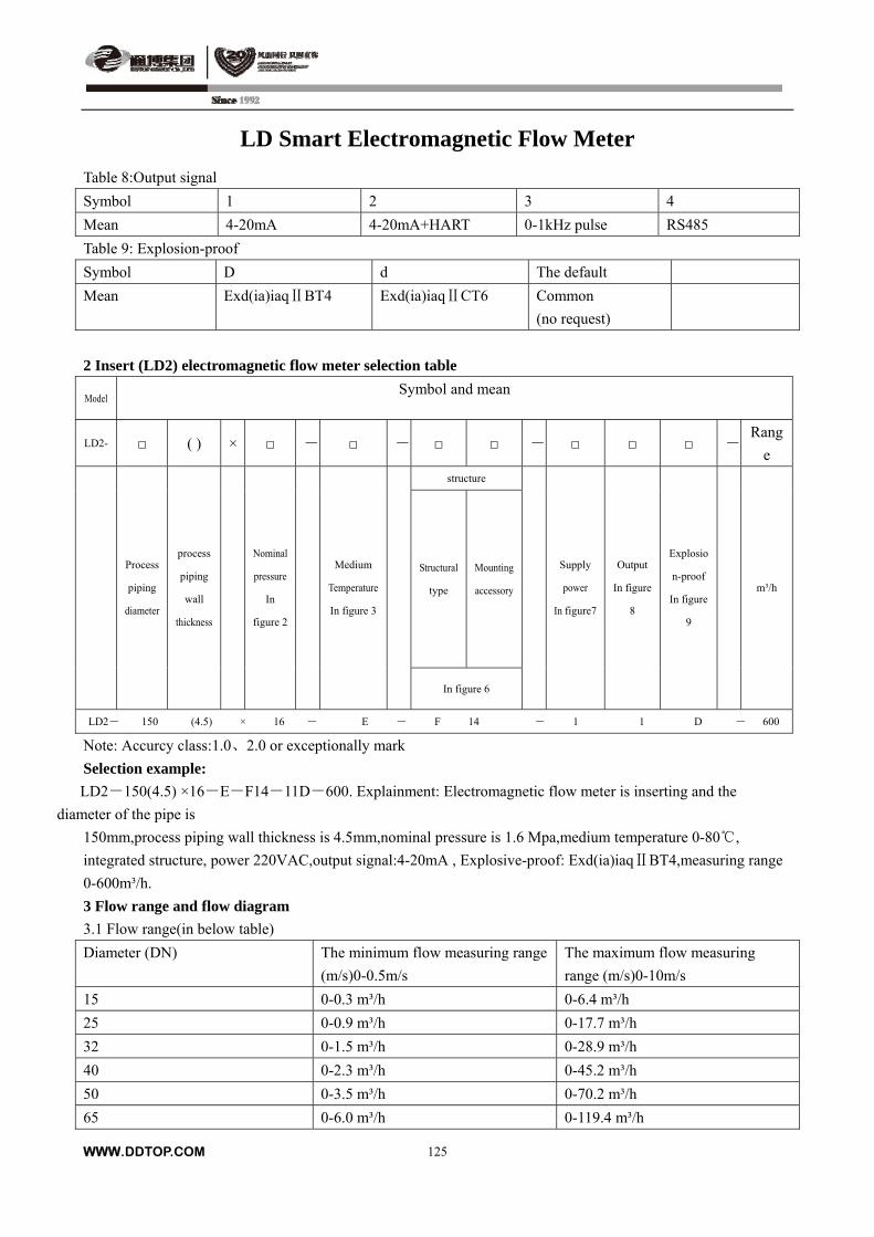
WWW.DDTOP.COM
125
LD Smart Electromagnetic Flow Meter
Table 8:Output signal
Symbol 1 2 3 4
Mean 4-20mA 4-20mA+HART 0-1kHz pulse RS485
Table 9: Explosion-proof
Symbol D d The default
Mean Exd(ia)iaq BT4Ⅱ Exd(ia)iaq CT6Ⅱ Common
(no request)
2 Insert (LD2) electromagnetic flow meter selection table
Model Symbol and mean
LD2- ( ) × - - - -Rang
e
structure
Structural
type
Mounting
accessory
Process
piping
diameter
process
piping
wall
thickness
Nominal
pressure
In
figure 2
Medium
Temperature
In figure 3
In figure 6
Supply
power
In figure7
Output
In figure
8
Explosio
n-proof
In figure
9
m³/h
LD2- 150 (4.5) × 16 - E - F 14 - 1 1 D - 600
Note: Accurcy class:1.0、2.0 or exceptionally mark
Selection example:
LD2-150(4.5) ×16-E-F14-11D-600. Explainment: Electromagnetic flow meter is inserting and the
diameter of the pipe is
150mm,process piping wall thickness is 4.5mm,nominal pressure is 1.6 Mpa,medium temperature 0-80 ,
integrated structure, power 220VAC,output signal:4-20mA , Explosive-proof: Exd(ia)iaq BT4,measuring range Ⅱ
0-600m³/h.
3 Flow range and flow diagram
3.1 Flow range(in below table)
Diameter (DN) The minimum flow measuring range
(m/s)0-0.5m/s
The maximum flow measuring
range (m/s)0-10m/s
15 0-0.3 m³/h 0-6.4 m³/h
25 0-0.9 m³/h 0-17.7 m³/h
32 0-1.5 m³/h 0-28.9 m³/h
40 0-2.3 m³/h 0-45.2 m³/h
50 0-3.5 m³/h 0-70.2 m³/h
65 0-6.0 m³/h 0-119.4 m³/h
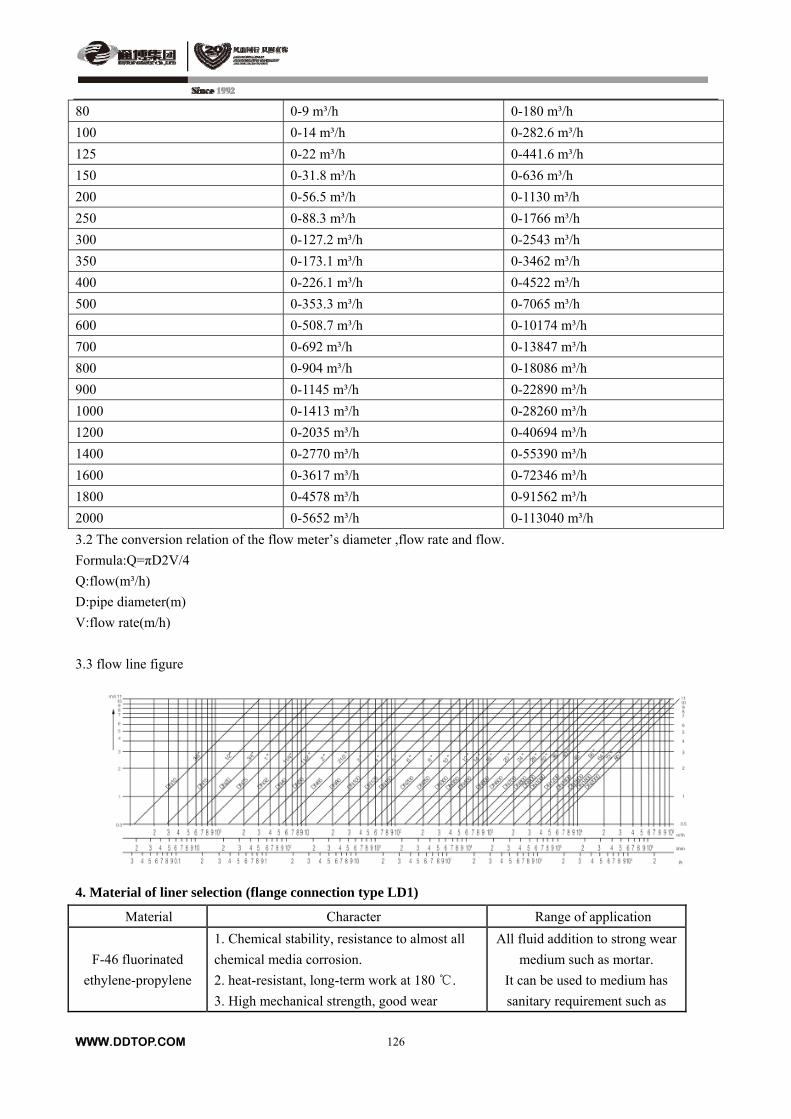
80 0-9 m³/h 0-180 m³/h
100 0-14 m³/h 0-282.6 m³/h
125 0-22 m³/h 0-441.6 m³/h
150 0-31.8 m³/h 0-636 m³/h
200 0-56.5 m³/h 0-1130 m³/h
250 0-88.3 m³/h 0-1766 m³/h
300 0-127.2 m³/h 0-2543 m³/h
350 0-173.1 m³/h 0-3462 m³/h
400 0-226.1 m³/h 0-4522 m³/h
500 0-353.3 m³/h 0-7065 m³/h
600 0-508.7 m³/h 0-10174 m³/h
700 0-692 m³/h 0-13847 m³/h
800 0-904 m³/h 0-18086 m³/h
900 0-1145 m³/h 0-22890 m³/h
1000 0-1413 m³/h 0-28260 m³/h
1200 0-2035 m³/h 0-40694 m³/h
1400 0-2770 m³/h 0-55390 m³/h
1600 0-3617 m³/h 0-72346 m³/h
1800 0-4578 m³/h 0-91562 m³/h
2000 0-5652 m³/h 0-113040 m³/h
3.2 The conversion relation of the flow meter’s diameter ,flow rate and flow.
Formula:Q=πD2V/4
Q:flow(m³/h)
D:pipe diameter(m)
V:flow rate(m/h)
3.3 flow line figure
4. Material of liner selection (flange connection type LD1)
Material Character Range of application
F-46 fluorinated
ethylene-propylene
1. Chemical stability, resistance to almost all
chemical media corrosion.
2. heat-resistant, long-term work at 180 .
3. High mechanical strength, good wear
All fluid addition to strong wear
medium such as mortar.
It can be used to medium has
sanitary requirement such as
WWW.DDTOP.COM
126

resistance.
4. The inner surface is smooth, and is not easy
to adhere to precipitate.
5. The inner lining with metal mesh,
vacuum-resistant, anti-vacuum.
drinks.
PO polyolefin
1. Has good physical and chemical properties,
is a more advanced anti-corrosion materials
now.
2. Long-term using at 80 .
3. Has good stress cracking resistance, better
than rubber.
4. Has good impact resistance.
5. Has good rigidity.
All fluid in addition to gasoline,
diesel and acetaldehyde, the
temperature is not higher than
80 .
PUR polyurethane
Good wear resistance, isn’t resistant to
corrosion, operating temperature can not
exceed 50
Mortar and other strong abrasive
fluids
5. Material of electrode selection (flange connection type LD1)
Material Corrosion resistance
Hc hastelloy C Anti-oxidizing acids such as nitric acid, chromic acid and sulfuric acid
mixture. Also resistant to oxidizing salts or other oxidant-containing
corrosive environment. Seawater, alkali solution, chloride solution with
good corrosion resistance.
Hb hastelloy B Sulfuric acid, phosphoric acid, hydrofluoric acid and other non-oxidizing
acid, alkali, salt, with good corrosion resistance.
Ta tantalum Addition to hydrofluoric acid, it can resist almost all chemical media.
Because of its price is so high, it is only used for hydrochloric acid and
concentrated sulfuric acid.
316L stainless steel It is used for weak corrosive medium such as industrial water, domestic
water and waste water, neutral solution and weak acid such as carbonic
acid and acetic acid.
6. Ground ring selection (flange connection type LD1 has this) as figure 4.
6.1 Standard ground ring: both sides of sensor must install ground ring on plastic and cathodic protection pipes.
6.2 protection ring with neck: if medium has strong abrasiveness, you should select protection ring with neck to
protect liner.
6.3 protection ring: F46 liner sensor should select protection ground ring, fixed on flange via screw to protect the
flanging of liner from damage.
WWW.DDTOP.COM
127

LD Smart Electromagnetic Flow Meter
The material of ground ring is stainless steel 1Cr18Ni9Ni, if you have special requirement, please tell us when
ordering goods.
7. Protection class selection of house
Protection class of the housing on integrated flow meter is IP65, the sensor section is IP68, and transmitter section
is IP65.
8. The determination of the fission
You should use split type flow meter in hostile environment such as ponding, corrosion, high temperature, low
temperature, strong vibration and maintenance inconveniently, etc.
Transmitter is connected to sensor only with a cable. Please ensure the specific length with the manufacturer when
ordering goods, if not, the length is only 5 meters. Others select integrated flow meter. When you can’t make the
decision, you can ask to manufacturer.
Outline and installation dimension
1、Structure and size of flange connection type(LD1 type)
WWW.DDTOP.COM
128
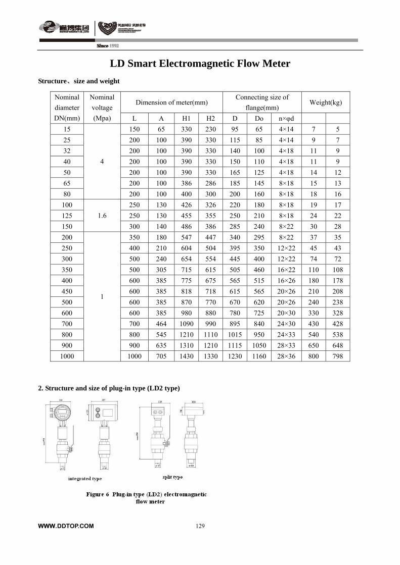
LD Smart Electromagnetic Flow Meter
Structure、size and weight
Dimension of meter(mm) Connecting size of
flange(mm) Weight(kg)
Nominal
diameter
DN(mm)
Nominal
voltage
(Mpa) L A H1 H2 D Do n×φd
15 150 65 330 230 95 65 4×14 7 5
25 200 100 390 330 115 85 4×14 9 7
32 200 100 390 330 140 100 4×18 11 9
40 200 100 390 330 150 110 4×18 11 9
50 200 100 390 330 165 125 4×18 14 12
65 200 100 386 286 185 145 8×18 15 13
80
4
200 100 400 300 200 160 8×18 18 16
100 250 130 426 326 220 180 8×18 19 17
125 250 130 455 355 250 210 8×18 24 22
150
1.6
300 140 486 386 285 240 8×22 30 28
200 350 180 547 447 340 295 8×22 37 35
250 400 210 604 504 395 350 12×22 45 43
300 500 240 654 554 445 400 12×22 74 72
350 500 305 715 615 505 460 16×22 110 108
400 600 385 775 675 565 515 16×26 180 178
450 600 385 818 718 615 565 20×26 210 208
500 600 385 870 770 670 620 20×26 240 238
600 600 385 980 880 780 725 20×30 330 328
700 700 464 1090 990 895 840 24×30 430 428
800 800 545 1210 1110 1015 950 24×33 540 538
900 900 635 1310 1210 1115 1050 28×33 650 648
1000
1
1000 705 1430 1330 1230 1160 28×36 800 798
2. Structure and size of plug-in type (LD2 type)
WWW.DDTOP.COM
129
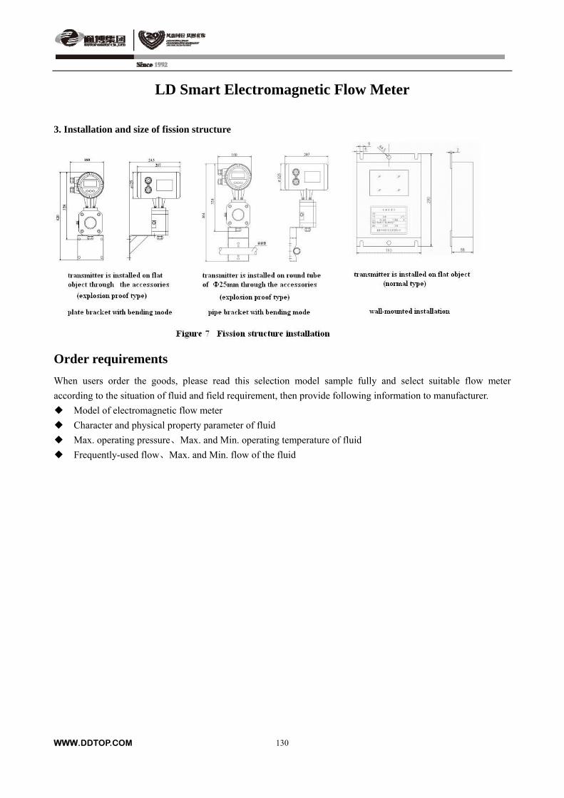
LD Smart Electromagnetic Flow Meter
3. Installation and size of fission structure
Order requirements
When users order the goods, please read this selection model sample fully and select suitable flow meter
according to the situation of fluid and field requirement, then provide following information to manufacturer.
Model of electromagnetic flow meter
Character and physical property parameter of fluid
Max. operating pressure、Max. and Min. operating temperature of fluid
Frequently-used flow、Max. and Min. flow of the fluid
WWW.DDTOP.COM
130
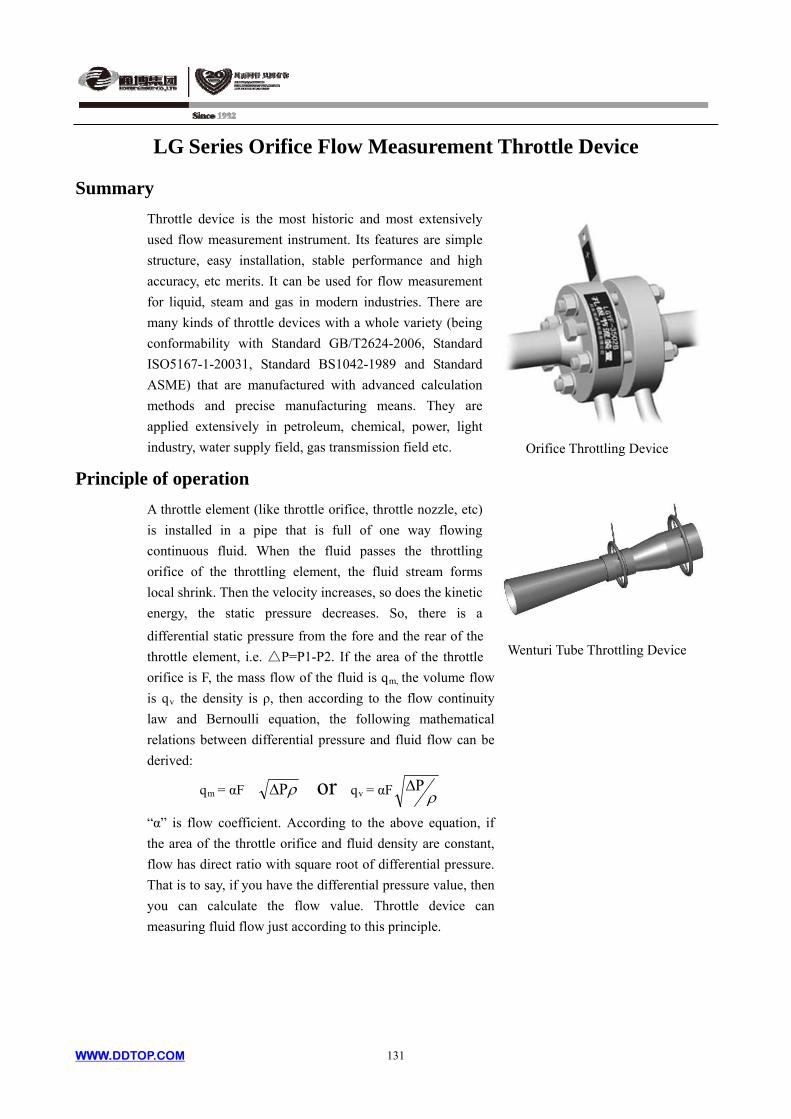
LG Series Orifice Flow Measurement Throttle Device
Summary
Throttle device is the most historic and most extensively
used flow measurement instrument. Its features are simple
structure, easy installation, stable performance and high
accuracy, etc merits. It can be used for flow measurement
for liquid, steam and gas in modern industries. There are
many kinds of throttle devices with a whole variety (being
conformability with Standard GB/T2624-2006, Standard
ISO5167-1-20031, Standard BS1042-1989 and Standard
ASME) that are manufactured with advanced calculation
methods and precise manufacturing means. They are
applied extensively in petroleum, chemical, power, light
industry, water supply field, gas transmission field etc. Orifice Throttling Device
Principle of operation
WWW.DDTOP.COM 131
A throttle element (like throttle orifice, throttle nozzle, etc)
is installed in a pipe that is full of one way flowing
continuous fluid. When the fluid passes the throttling
orifice of the throttling element, the fluid stream forms
local shrink. Then the velocity increases, so does the kinetic
energy, the static pressure decreases. So, there is a
differential static pressure from the fore and the rear of the
throttle element, i.e. P=P1-P2. If the area of the throttle
orifice is F, the mass flow of the fluid is qm, the volume flow
is qv the density is ρ, then according to the flow continuity
law and Bernoulli equation, the following mathematical
relations between differential pressure and fluid flow can be
derived:
Wenturi Tube Throttling Device
qm = αF or qv = αF
“α” is flow coefficient. According to the above equation, if
the area of the throttle orifice and fluid density are constant,
flow has direct ratio with square root of differential pressure.
That is to say, if you have the differential pressure value, then
you can calculate the flow value. Throttle device can
measuring fluid flow just according to this principle.
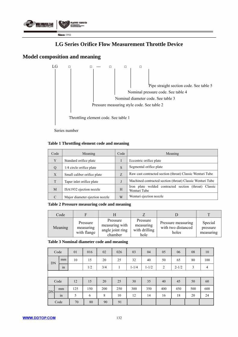
LG Series Orifice Flow Measurement Throttle Device
Model composition and meaning
LG ---
Pipe straight section code. See table 5
WWW.DDTOP.COM 132
Nominal pressure code. See table 4
Nominal diameter code. See table 3
Pressure measuring style code. See table 2
Throttling element code. See table 1
Series number
Table 1 Throttling element code and meaning
Code Meaning Code Meaning
Y Standard orifice plate I Eccentric orifice plate
Q 1/4 circle orifice plate S Segmental orifice plate
X Small caliber orifice plate Z Raw cast contracted section (throat) Classic Wenturi Tube
T Taper inlet orifice plate J Machined contracted section (throat) Classic Wenturi Tube
M ISA1932 ejection nozzle H Iron plate welded contracted section (throat) Classic Wenturi Tube
C Major diameter ejection nozzle W Wenturi ejection nozzle
Table 2 Pressure measuring code and meaning
Code F H Z D T
Meaning Pressure
measuring with flange
Pressure measuring with angle joint ring
chamber
Pressure measuring
with drilling hole
Pressure measuring with two distanced
holes
Special pressure
measuring
Table 3 Nominal diameter code and meaning
Code 01 016 02 026 03 04 05 06 08 10
mm 10 15 20 25 32 40 50 65 80 100 DN
in 1/2 3/4 1 1-1/4 1-1/2 2 2-1/2 3 4
Code 12 15 20 25 30 35 40 45 50 60
mm 125 150 200 250 300 350 400 450 500 600 DN
in 5 6 8 10 12 14 16 18 20 24
Code 70 80 90 91
WWW.DDTOP.COM 133
DN mm 700 800 900 1000
in 28 32 36 40
Table 4 Nominal pressure code and meaning
Code 01 02 03 04 05 06 10 11 15 16
MPa 1.6 2.0 2.5 4.0 5.0 6.3 10.0 11.0 15.0 16.0PN
Class 150 300 600 900
Code 25 26 42
MPa 25.0 26.0 42.0 PN
Class 1500 2500
Table 5 Straight pipe section code and meaning
Code No A B C D E F
Meaning Throttle element
Throttle element, with flange
Throttle element, with flange, with upper and lower straight pipe section
Throttle element, with flange, with upper and lower straight pipe section, with upper and lower connection flange
Throttle element, with flange, with upper and lower straight pipe section, with upper connection flange
Throttle element, with flange, with upper and lower straight pipe section, with lower connection flange
Welding structure
2. Standards 2.1. Standards for throttle element
Table 6 Standards for throttling element
Code Meaning Standards code
Y Standard orifice plate GB/T2624-2006 (ISO5167-2003)
Q 1/4 circle orifice plate BS1042-1989
X Small caliber orifice plate GB2624-2006
T Taper inlet orifice plate BS1042-1989
M ISA1932 nozzle GB/T2624-2006 (ISO5167-2003)
C Major diameter nozzle GB/T2624-2006 (ISO5167-2003)
I Eccentric orifice plate ASME
S Segmental orifice plate ASME
Z Raw cast contracted section (throat) Classic Wenturi Tube
GB/T2624-2006 (ISO5167-2003)
J Machined contracted section (throat) Classic Wenturi Tube
GB/T2624-2006 (ISO5167-2003)
H Iron plate welded contracted section (throat) Classic Wenturi Tube
GB/T2624-2006 (ISO5167-2003)
W Wenturi nozzle GB/T2624-2006 (ISO5167-2003)
2.2 Flange & Gasket standards
Standards for flanges and gaskets: you can select JB Standard, HG20592 ~ 20614-2009 (European
system), HG20615-20635-2009 (American system) or other standards1. Application range for
throttling elements
LG Series Orifice Flow Measurement Throttle Device
Installation dimensions of throttle device
1. 1.0-6.3 MPa installation dimensions of throttle device with flange pressure measuring
1. Flowing direction 2. Holeφ23 to be connected to the pressure measuring tube φ22
WWW.DDTOP.COM 134

WWW.DDTOP.COM 135
LG Series Orifice Flow Measurement Throttle Device
Nominal diameter DN D LA LB LC
10 90 126 276 422
15 95 126 351 497
20 105 128 428 586
25 115 132 507 673
32 135 132 612 786
40 145 138 738 924
50 160 139 889 1075
65 180 141 1116 1314
80 195 146 1346 1552
100 215 146 1646 1860
125 245 159 2034 2280
150 280 159 2409 2655
200 335 163 3163 3417
For the above table, the length of the front straight section should be 10 times as long as the
nominal diameter, the length of the rear straight section should be 5 times as long as the
nominal diameter;
For the below table, the length of the front straight section should be 2000mm, the length of the
rear straight section should be 1000mm.
250 390 166 3166 3432
300 440 162 3162 3428
350 500 164 3164 3430
400 565 164 3164 3430
450 615 176 3176 3462
500 670 190 3190 3508
600 780 212 3212 3578
700 895 210 3210 3576
800 1010 238 3238 3668
900 1110 242 3242 3680
1.0MPa
1000 1220 242 3242 3680
WWW.DDTOP.COM 136
LG Series Orifice Flow Measurement Throttle Device
Nominal diameter DN D LA LB LC
10 90 122 272 418
15 95 122 347 493
20 105 128 428 586
25 115 132 507 673
32 135 132 612 786
40 145 138 738 924
50 160 145 895 1093
65 180 145 1120 1326
80 195 146 1346 1560
100 215 146 1646 1860
125 245 159 2034 2280
150 280 159 2409 2655
200 335 159 3159 3413
For the above table, the length of the front straight section should be 10 times as long as the
nominal diameter, the length of the rear straight section should be 5 times as long as the
nominal diameter;
For the below table, the length of the front straight section should be 2000mm, the length of the
rear straight section should be 1000mm.
250 405 168 3168 3446
300 460 168 3168 3454
350 520 178 3178 3496
400 580 149 3194 3560
450 640 206 3206 3592
500 705 212 3212 3610
600 840 226 3226 3652
700 910 238 3238 3684
800 1020 248 3248 3714
900 1120 266 3266 3760
1.6MPa
1000 1255 272 3272 3778
WWW.DDTOP.COM 137
LG Series Orifice Flow Measurement Throttle Device
Nominal diameter DN D LA LB LC
10 90 122 272 418
15 95 122 347 493
20 105 128 428 586
25 115 132 507 673
32 135 132 612 786
40 145 138 738 924
50 160 145 895 1093
65 180 145 1120 1326
80 195 146 1346 1560
100 230 184 1684 1938
125 270 197 2072 2350
150 300 205 2455 2749
200 360 221 3221 3547
For the above table, the length of the front straight section should be 10 times as long as the
nominal diameter, the length of the rear straight section should be 5 times as long as the
nominal diameter;
For the below table, the length of the front straight section should be 2000mm, the length of the
rear straight section should be 1000mm.
250 425 232 3232 3578
300 485 246 3246 3620
350 550 260 3260 3658
400 610 294 3294 3760
450 660 296 3296 3762
500 730 306 3306 3792
600 840 326 3326 3852
700 955 348 3348 3914
2.5MPa
800 1070 368 3368 3974
WWW.DDTOP.COM 138
LG Series Orifice Flow Measurement Throttle Device
Nominal diameter DN D LA LB LC
10 90 114 264 404
15 95 114 339 479
20 105 116 416 560
25 115 120 495 647
32 135 134 614 794
40 145 138 738 930
50 160 135 885 1077
65 180 151 1126 1334
80 195 148 1348 1580
100 230 164 1664 1936
125 270 161 2036 2308
150 300 165 2415 2703
200 375 181 3181 3533
For the above table, the length of the front straight section should be 10 times as long as the
nominal diameter, the length of the rear straight section should be 5 times as long as the
nominal diameter;
For the below table, the length of the front straight section should be 2000mm, the length of the
rear straight section should be 1000mm.
250 445 208 3208 3616
300 510 236 3236 3700
350 570 246 3246 3726
400 655 290 3290 3858
450 680 300 3300 3884
4.0MPa
500 755 320 3320 3944
LG Series Orifice Flow Measurement Throttle Device
Nominal diameter DN D LA LB LC
10 100 136 361 553
15 105 136 286 478
20 125 148 448 672
25 135 148 523 755
32 150 152 632 880
40 165 166 766 1038
50 175 167 917 1197
65 200 173 1148 1448
80 210 170 1370 1670
100 250 176 1676 1996
125 295 205 2080 2472
150 340 221 2471 2903
200 405 235 3235 3699
For the above table, the length of the front straight section should be 10 times as long as the
nominal diameter, the length of the rear straight section should be 5 times as long as the
nominal diameter;
For the below table, the length of the front straight section should be 2000mm, the length of the
rear straight section should be 1000mm.
250 470 248 3248 3736
300 530 276 3276 3820
350 595 314 3314 3930
6.3MPa
400 670 346 3346 4026
2. 1.0-6.3 MPa installation dimensions of throttle device with ring chamber pressure measuring
1. Flow direction
WWW.DDTOP.COM 139
LG Series Orifice Flow Measurement Throttle Device
1. Flow direction
Nominal diameter DN D LA LB LC 10 90 129 279 425 15 95 129 354 500 20 105 135 435 593 25 115 139 514 680 32 135 143 623 797
40 145 149 749 935 50 160 149 899 1085 65 180 155 1130 1328 80 195 160 1360 1566
100 215 164 1664 1878
125 245 181 2056 2302 150 280 181 2431 2677 200 335 185 3185 3439
For the above table, the length of the front straight section should be 10 times as long as the nominal diameter, the length of the rear straight section should be 5 times as long as the nominal diameter; For the below table, the length of the front straight section should be 2000mm, the length of the rear straight section should be 1000mm.
250 390 192 3192 3458 300 440 192 3192 3458 350 500 194 3194 3460 400 565 194 3194 3460 450 615 206 3206 3492
500 670 222 3222 3540 600 780 246 3246 3612 700 895 248 3248 3614 800 1010 280 3280 3710 900 1110 288 3288 3726
1.0MPa
1000 1220 288 3288 3726
WWW.DDTOP.COM 140
WWW.DDTOP.COM 141
LG Series Orifice Flow Measurement Throttle Device
Nominal diameter DN D LA LB LC
10 90 129 279 425
15 95 129 354 500
20 105 135 435 593
25 115 139 514 680
32 135 143 623 797
40 145 149 749 935
50 160 155 905 1103
65 180 159 1134 1340
80 195 164 1364 1578
100 215 164 1664 1878
125 245 181 2056 2302
150 280 181 2431 2677
200 335 185 3185 3439
For the above table, the length of the front straight section should be 10 times as long as the
nominal diameter, the length of the rear straight section should be 5 times as long as the
nominal diameter;
For the below table, the length of the front straight section should be 2000mm, the length of the
rear straight section should be 1000mm.
250 405 198 3198 3476
300 460 202 3202 3488
350 520 220 3220 3538
400 580 244 3244 3610
450 640 256 3256 3642
500 705 262 3262 3660
600 840 276 3276 3702
700 910 288 3288 3734
800 1020 298 3298 3764
900 1120 316 3316 3810
1.6MPa
1000 1255 322 3322 3828
WWW.DDTOP.COM 142
LG Series Orifice Flow Measurement Throttle Device
Nominal diameter DN D LA LB LC
10 90 129 279 425
15 95 129 354 500
20 105 131 431 581
25 115 135 510 668
32 135 149 629 815
40 145 155 755 953
50 160 155 905 1103
65 180 163 1138 1352
80 195 170 1370 1596
100 230 184 1684 1938
125 270 197 2072 2350
150 300 205 2455 2749
200 360 221 3221 3547
For the above table, the length of the front straight section should be 10 times as long as the
nominal diameter, the length of the rear straight section should be 5 times as long as the
nominal diameter;
For the below table, the length of the front straight section should be 2000mm, the length of the
rear straight section should be 1000mm.
250 425 232 3232 3578
300 485 246 3246 3620
350 550 260 3260 3658
400 610 294 3294 3760
450 660 296 3296 3762
500 730 306 3306 3792
600 840 326 3326 3852
700 955 348 3348 3914
2.5MPa
800 1070 368 3368 3974
WWW.DDTOP.COM 143
LG Series Orifice Flow Measurement Throttle Device
Nominal diameter DN D LA LB LC
10 90 129 279 419
15 95 129 354 494
20 105 131 431 575
25 115 135 510 662
32 135 149 629 809
40 145 155 755 947
50 160 155 905 1097
65 180 175 1150 1358
80 195 176 1376 1608
100 230 196 1696 1968
125 270 197 2072 2344
150 300 205 2455 2743
200 375 237 3237 3589
For the above table, the length of the front straight section should be 10 times as long as the
nominal diameter, the length of the rear straight section should be 5 times as long as the
nominal diameter;
For the below table, the length of the front straight section should be 2000mm, the length of
the rear straight section should be 1000mm.
250 445 266 3266 3674
300 510 294 3294 3758
350 570 304 3304 3784
400 655 348 3348 3916
450 680 358 3358 3942
4.0MPa
500 755 378 3378 4002
LG Series Orifice Flow Measurement Throttle Device
Nominal diameter DN D LA LB LC
10 100 155 305 497
15 105 155 380 572
20 125 171 471 695
25 135 175 550 782
32 150 183 663 911
40 165 195 795 1067
50 175 199 949 1229
65 200 209 1184 1484
80 210 210 1410 1710
100 250 220 1720 2040
125 295 257 2132 2524
150 340 277 2527 2959
200 405 293 3293 3757
For the above table, the length of the front straight section should be 10 times as long as the
nominal diameter, the length of the rear straight section should be 5 times as long as the
nominal diameter;
For the below table, the length of the front straight section should be 2000mm, the length of
the rear straight section should be 1000mm.
250 470 306 3306 3794
300 530 323 3323 3867
350 595 372 3372 3988
6.3MPa
400 670 404 3404 4084
3. 10.0-16.0 MPa installation dimensions of throttle device with flange pressure measuring
1. Flow direction
WWW.DDTOP.COM 144
WWW.DDTOP.COM 145
LG Series Orifice Flow Measurement Throttle Device
Nominal diameter DN D LA LB
10 100 140 290
15 105 142 367
20 125 154 454
25 135 154 529
32 150 162 642
40 165 174 774
50 195 195 945
65 220 203 1178
80 230 206 1406
100 265 226 1726
125 310 258 2133
150 350 288 2538
200 430 318 3318
For the above table, the length of the front straight section should be 10 times as long as the
nominal diameter, the length of the rear straight section should be 5 times as long as the
nominal diameter;
For the below table, the length of the front straight section should be 2000mm, the length of
the rear straight section should be 1000mm.
250 500 369 3369
300 585 419 3419
350 665 457 3457
10.0MPa
400 715 477 3477
LG Series Orifice Flow Measurement Throttle Device
Nominal diameter DN D LA LB
10 110 138 363
15 130 144 444
20 140 140 515
25 165 146 626
32 175 152 752
50 215 229 956
65 245 236 1211
80 260 247 1477
100 300 267 1767
125 355 308 2183
150 390 343 2593
200 480 404 3404
For the above table, the length of the front straight section should be 10 times as long as the
nominal diameter, the length of the rear straight section should be 5 times as long as the
nominal diameter;
For the below table, the length of the front straight section should be 2000mm, the length of
the rear straight section should be 1000mm.
250 580 493 3493
16.0MPa
300 665 592 3592
4. 26.0-42.0 MPa installation dimensions of throttle device with flange pressure measuring
1. Flow direction
WWW.DDTOP.COM 146
WWW.DDTOP.COM 147
LG Series Orifice Flow Measurement Throttle Device
Nominal diameter DN D LA LB LC 15 120 160 20 130 174 25 150 172 32 160 172 40 180 186
50 215 226 65 245 232 80 270 259
100 310 271
125 375 334 150 395 370 200 485 457
For the above table, the length of the front straight section should be 10 times as long as the nominal
diameter, the length of the rear straight section should be 5 times as long as the nominal diameter;
For the below table, the length of the front straight section should be 2000mm, the length of the rear straight section should be 1000mm.
250 585 540
26.0MPa
300 675 607
Nominal diameter DN D LA LB LC 15 135 170 20 140 178 25 160 196 32 185 212 40 205 244 50 235 276 65 270 292 80 305 363 100 355 410 125 420 493 150 485 589 200 550 674
For the above table, the length of the front straight section should be 10 times as long as the
nominal diameter, the length of the rear straight section should be 5 times as long as the nominal
diameter;
For the below table, the length of the front straight section should be 2000mm, the length of the rear straight section should be 1000mm.
250 675 884
42.0MPa
300 760 978
LG Series Orifice Flow Measurement Throttle Device
5. Other throttle device 5.1 Nozzle
Angle joint ring chamber pressure taking is adopted for installation dimensions of ISA1932 nozzle and Wenturi
nozzle, see the table of “1.0-6.3 MPa installation dimensions of throttle device with ring chamber pressure
measuring”.
Distanced holes pressure taking is adopted for installation dimensions of major diameter ejection nozzle, see the
table of “26.0-42.0 MPa installation dimensions of throttle device with flange pressure measuring”.
5.2 Wenturi tube
This device is high accuracy, performance stable, low pressure lost (normally is 5% ~ 20% of differential pressure)
and easy to maintain. Especially in current energy saving condition, it is measurement accuracy and energy
decreasing, etc, so has widely use in application.
L = D + d + 5.10tg2
dD +
42tg
dD
D – inner diameter of pipe (mm); d – inner diameter at throat section (contract section) of Wenturi tube (mm)
5.3 Welding throttle device
It is one kind of throttle device, simple structure, cost saving, short production time and no leakage, etc.
Especially for measuring industrial high temperature, fluid flow in high pressure pipe and steam flow.
Installation dimensions
WWW.DDTOP.COM 148
WWW.DDTOP.COM 149
LG Series Orifice Flow Measurement Throttle Device
Order requirements
1. When purchasing throttle device, please fill in the specification table of throttle device (see below)
Project NO.
Table NO. Throttle Device Parameters Table Page. Total.
Data Calculation
Fluid name Throttle element type
Operating temperature Pressure taking type
Operating pressure MPa Select scale
Liquid kg/h Max. Select differential pressure kPa
Steam kg/h Nor. Min. flow limit
Gas(standard) Nm3/h Min. Reynolds number Re (normal flow)
Liquid kg/m3 Area expansion correction coefficient Fa
Steam kg/m3 Expansion coefficient ε
Gas (standard) kg/m3 Flow coefficient α
Flo
w
Uncertainty %
Permanent pressure loss Pa
Diameter ratio βt
Hole diameter of throttle mm element or segmental height
1/4 circle radius or eccentricity degree mm
Operating density kg/m3 Throttle device standard
Dynamic viscosity mPa.s
Kinematic viscosity mm2/s Specification
Relative humidity (Φ)
Compression coefficient (Z) Model
Isentropic exponent (cp/cv) Normal diameter (DN)
Ope
ratio
n co
nditi
ons
Allowable pressure loss Pa Normal pressure (PN) MPa
Nominal diameter (DN) Flange standard
Pipe instrument number Flange inner diameter mm
Outside diameter/inner diameter mm Structural length mm Pip
e
Material Pressure tape size mm
Pressure tape location
Throttle element
Flange
Bolt
Nut
mat
eria
l
Gasket
Remark
WWW.DDTOP.COM 150
LG Series Orifice Flow Measurement Throttle Device
2. We supply the following services:
2.1 To supply different kinds of the above mentioned throttle device in set.
2.2 To supply calculation for the throttle device that the customer owns, including:
1) The diameter of the open pore of throttle element d20 and the instrument recommended flow value are known,
on new working conditions, calculate upper limit Hmax of the new differential pressure of the instrument.
2) The diameter of the open pore of throttling element d20, the upper limit Hmax of the instrument differential
pressure and the original instrument recommended flow value, calculate new instrument recommended flow value
on new working conditions.
2.3 According to the customer’s requirements or drawings, to manufacture the throttle devices.
LGXL Throttling Orifice Device
Summary
Throttling orifice is suitable for automatic control, piping and other professional situations in the
engineering design, here are several occasions which are frequently used :
a. It required that fluid with small flow continuously passing it, such as analysis on the sampling
pipeline, pump flush pipeline, hot standby pump bypass line and so on, can set the current
limit orifice to implement;
b. It required fluid step-down occasions, such as setting limit flow orifice after the control valve
to minimize the pressure drop on the valve, reduce the noise of the valve, reduce the wear of
valve seat and valve element, avoid liquid flash vaporization and cavitation phenomenon
behind the valve, prolong the service life of the valve; Fluid requires step-down, you can use
the current limit orifice plate to step-down for the application that step-down precision is not
high;
c. Application required fluid step-down and current limiting, such as setting the current limit
orifice plate on bypass control valve, in order to prevent the operation of the bypass, liquid
pressure drops too fast or causes danger such as liquid evacuated. For piping emptying
system, when big pressure drops and produces a lot of noise, you can use current-limiting
orifice plate to reduce the noise, to improve the production environment.
Model Selection Table
L G X L —
Straight pipe code as figure 3
WWW.DDTOP.COM
151
Nominal pressure code as figure 2
Nominal diameter code as figure 1
Serial number
figure 1 Nominal diameter code and meaning
Code 01 016 02 026 03 04 05 06 08 10
mm 10 15 20 25 32 40 50 65 80 100 DN
in 1/2 3/4 1 1-1/4 1-1/2 2 2-1/2 3 4
Code 12 15 20 25 30 35 40 45 50 60
mm 125 150 200 250 300 350 400 450 500 600 DN
in 5 6 8 10 12 14 16 18 20 24
Code 70 80 90 91 92 93
mm 700 800 900 1000 1100 1200 DN
in 28 32 36 40 44 48
WWW.DDTOP.COM
152
LGXL Throttling Orifice
Figure 2 Nominal pressure code and meaning
Code 01 02 03 04 05 06 10 11 15 16
MPa 1.6 2.0 2.5 4.0 5.0 6.3 10.0 11.0 15.0 16.0 PN
Class 150 300 600 900
Code 25 26 42
MPa 25.0 26.0 42.0 PN
Class 1500 2500
Figure 3 Straight pipe code and meaning
Code None A B C D E F
Meaning Throttling element
Throttling element Installation of flange
Throttling element Installation of flange Upstream and downstream straight pipe
Throttling element Installation of flange Upstream and downstream straight pipeUpstream and downstream connecting flange
Throttling element Installation of flange Upstream and downstream straight pipe Upstream connecting flange
Throttling element Installation of flange Upstream and downstream straight pipe Downstream connecting flange
Welding Structure
LGXL Throttling Orifice
Outline and installation
1 construction
2 Installations 2.1 flange installation
Making throttling orifice plate installed between a pair of flanges tightly, and to keep
throttling orifice plate and pipe concentric and make the throttling orifice plate
perpendicular to the center line of the pipeline.
2.2 Embedded pipe welding installation
This installation, can be single throttling orifice plate, can also be multiple throttling orifice
plate, but in the appropriate position in front of current throttling orifice plate, should be
equipped with a flange in order to check when maintaining.
2.3 Pipe butt welding and installation
The installation type that throttling orifice plate with the pipe butt welding directly, usually
should not be used, because it is not convenient to check and replace.
2.4 When throttling orifice plate and control valve is installed in series, you must notice that the
pressure drop of the control valve and throttling orifice plate should be allocated
reasonably, to ensure that the control valve operates well in the control system functions.
2.5 The advisable installation position of throttling orifice plate is usually after the control
valve.
.
WWW.DDTOP.COM
153

WWW.DDTOP.COM
154
LGXL Throttling Orifice
Ordering information
Please fill in the following tables,when ordering throttling orifice plate.
Order company tag Tag No. Quantity
Users provide data Design results of our factory
Measured fluid name Pipe specification
(inner dia.) fluid density (kg/m3)
Schedule pressure (MPa)
Pipe Material (New) fluid viscosity
(mPa.S)
Operating temperature()
Throttling parts
material Full scale flow (Kg/h)
Density(kg/m3) Local atmospheric
pressure (MPa)
Full scale pressure drop (MPa)
Max. Common flow(Kg/h)
Nor. Common pressure
drop (MPa)
Flow Kg/h
Min.
Application parameters
Pipe inner dia.(mm)
Components name
Flange standard and
specification
volume ratio % Flange surface type
The molecular weight of pure components
Full scale pressure
drop (MPa)
For gas
The density of pure component
Orifice plate number
Heat capacity
ratio β(d/D)
relative humidity Supply of straight
pipe length
Number of single hole ×bore
Design parameters
Remark
LGV V Internal Cone Flow Meter
Summary LGV V type internal cone flowmeter is the second generation of inner cone flowmeter, is a kind of
high performance differential pressure type flow measuring instrument and it’s Dandong Top
Electronics Instrument (Group) Co.,Ltd. and Tianjin University cooperative development. The
unique support body and variable angle designed, can make it under the conditions of short straight
pipe, the metallurgy, chemical industry, chemical fertilizer, chemical fiber, oil, natural gas, electric,
hydraulic, and other industrial enterprises in various mediums such as gas, liquid and steam flow
measurement. It has strong cone, short straight pipe, high measurement precision, wide range ratio,
small pressure loss and low cost of installation and other characteristics, is a breakthrough in the
field of flow sensor technology in recent years, it makes up for the orifice, nozzle, venturi tube and
other standard throttle device’s structure defects, and has broad market prospects.
Operating Principle
V type internal cone flow meter is installed in the measuring tube and pipe concentric cone,
internal cone with special design and precision machining. When fluid flows through the internal
cone, the formation of local shrinkage, flow velocity increased, static pressure dropped, differential
pressure P generated left and right of the inner cone, like other differential pressure type flow
meters, are based on the fluid mass conservation( continuity equation) and energy conservation
laws(Bernoulli equation). The basic flow equations are as follows:
V type internal cone flow meter schematic diagram
PD
Cq m
2
41
2V
2
4V
m
v
2
2
1D
dVv
Among:qm: mass flux ; qv:volume flow ;C: discharge coefficient ;βV:The equivalent diameter ratio
ρ:Working condition of fluid density ; P:Pressure difference ; D:internal diameter of the pipeline
dV :The maximum cross sectional diameter of cone; ε:Gas expansion coefficient (liquid is 1)
WWW.DDTOP.COM
155
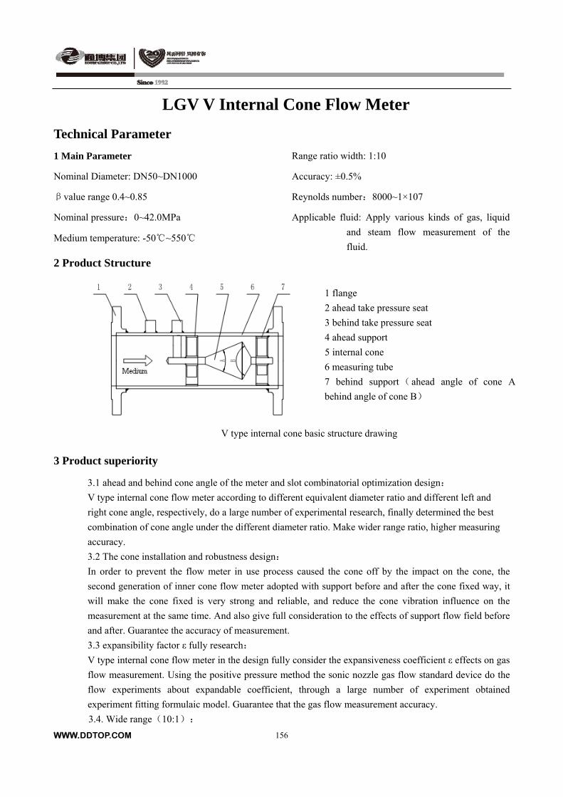
LGV V Internal Cone Flow Meter
Technical Parameter
1 Main Parameter Range ratio width: 1:10
Accuracy: ±0.5% Nominal Diameter: DN50~DN1000
Reynolds number:8000~1×10⁷ βvalue range 0.4~0.85
Applicable fluid: Apply various kinds of gas, liquid
and steam flow measurement of the
fluid.
Nominal pressure:0~42.0MPa
Medium temperature: -50~550
2 Product Structure
1 flange
2 ahead take pressure seat
3 behind take pressure seat
4 ahead support
5 internal cone
6 measuring tube
7 behind support(ahead angle of cone A
behind angle of cone B)
V type internal cone basic structure drawing
3 Product superiority
3.1 ahead and behind cone angle of the meter and slot combinatorial optimization design:
V type internal cone flow meter according to different equivalent diameter ratio and different left and
right cone angle, respectively, do a large number of experimental research, finally determined the best
combination of cone angle under the different diameter ratio. Make wider range ratio, higher measuring
accuracy.
3.2 The cone installation and robustness design:
In order to prevent the flow meter in use process caused the cone off by the impact on the cone, the
second generation of inner cone flow meter adopted with support before and after the cone fixed way, it
will make the cone fixed is very strong and reliable, and reduce the cone vibration influence on the
measurement at the same time. And also give full consideration to the effects of support flow field before
and after. Guarantee the accuracy of measurement.
3.3 expansibility factor ε fully research:
V type internal cone flow meter in the design fully consider the expansiveness coefficient ε effects on gas
flow measurement. Using the positive pressure method the sonic nozzle gas flow standard device do the
flow experiments about expandable coefficient, through a large number of experiment obtained
experiment fitting formulaic model. Guarantee that the gas flow measurement accuracy.
3.4. Wide range(10:1):
WWW.DDTOP.COM
156
WWW.DDTOP.COM
156
LGV V Internal Cone Flow Meter
V type internal cone flow meter throttling way is based on the side wall gradually shrink, make the whole
negative pressure zone vortex interference is suppressed, influence on the measurement of static pressure
becomes very small, even in the condition of small flow, also can get high signal-to-noise ratio, make the
measurement carried out as normal. This is one of the reason that scope of the V type internal cone flow
meter measurement range is better than other differential pressure flow meter.
3.5. Has a function of rectifier for the fluid flow state, so only need a very short straight pipe(ahead 3D
behind 2D):
V type internal cone flow meter characteristic of the side wall structure, make the fluid flows through the
cone to correct and rectify all kinds of the irregular flow distortion of upstream, which realize forming
regular flow of flow measurement area. So it takes only a short straight pipe can obtain accurate
measurements. Greatly facilitate the users.
3.6. Low pressure loss, good for energy saving
V type internal cone flow meter’s structure feature is streamline throttle device, it is low pressure loss
(about 1/3 of the orifice plate), huge advantage in measuring low pressure & high flow rate fluid.
Meanwhile, low pressure loss means low energy cost, so it can satisfy the energy saving request of
enterprise.
3.7. Long life and stable performance:
The boundary layer effect of V type internal cone flow meter is its specific structure which will protect
the main part of throttle device without wearing. It can keep the size of geometric figure for long time so
that it can work steadily in long
term and without calibration. Meanwhile, there is no movable parts on it (doesn’t include any electrical
parts), it is purely mechanical body, high temperature & pressure resistance, corrosion resistance and
vibration resistance.
4. Application
4.1、Gas
Coal gas(dirty coke oven gas、blast furnace gas、producer gas)
natural gas,Include moisture content more than 5% of the natural gas; All kinds of hydrocarbon gas;
All kinds of rare gas(Including gases used for process control); air,Including water, containing other
dust in the air
4.2、steam
saturated vapor;Superheated steam
4.3、Liquid
Oils, including crude oil(Under the certain viscosity);
Water, including pure water, sewage;
All kinds of aqueous solutions, including salts and aqueous alkali.
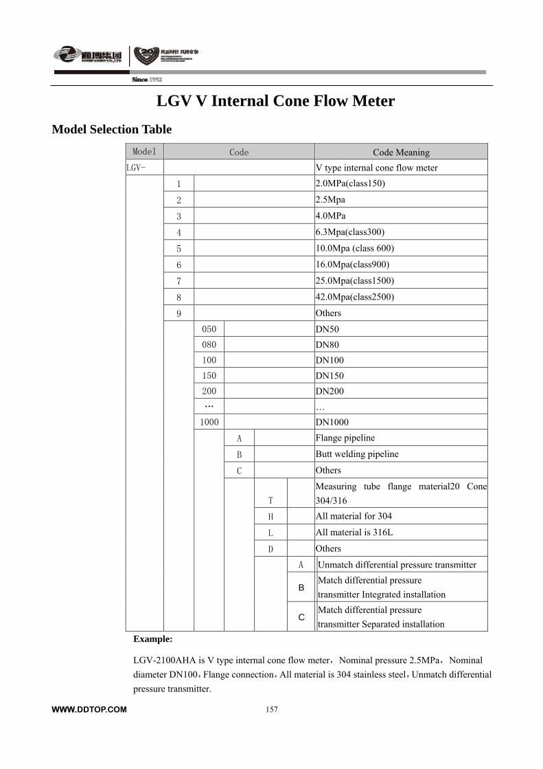
WWW.DDTOP.COM
157
LGV V Internal Cone Flow Meter
Model Selection Table
Model Code Code Meaning
LGV- V type internal cone flow meter
1 2.0MPa(class150)
2 2.5Mpa
3 4.0MPa
4 6.3Mpa(class300)
5 10.0Mpa (class 600)
6 16.0Mpa(class900)
7 25.0Mpa(class1500)
8 42.0Mpa(class2500)
9 Others
050 DN50
080 DN80
100 DN100
150 DN150
200 DN200
… …
1000 DN1000
A Flange pipeline
B Butt welding pipeline
C Others
T
Measuring tube flange material20 Cone
304/316
H All material for 304
L All material is 316L
D Others
A Unmatch differential pressure transmitter
B Match differential pressure
transmitter Integrated installation
C Match differential pressure
transmitter Separated installation
Example:
LGV-2100AHA is V type internal cone flow meter,Nominal pressure 2.5MPa,Nominal
diameter DN100,Flange connection,All material is 304 stainless steel,Unmatch differential
pressure transmitter.
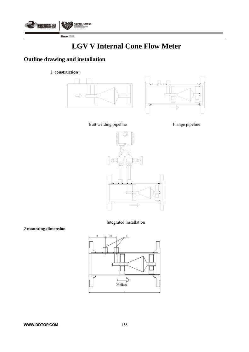
LGV V Internal Cone Flow Meter
Outline drawing and installation
1 construction:
Butt welding pipeline Flange pipeline
Integrated installation
2 mounting dimension
WWW.DDTOP.COM
158
WWW.DDTOP.COM
159
nominal diameter L(mm) B(mm) C
DN50 350 90 1/2NPT
DN80 450 90 1/2NPT
DN100 500 120 1/2NPT
DN150 600 130 1/2NPT
DN200 720 130 1/2NPT
DN250 830 150 1/2NPT
DN300 900 160 1/2NPT
DN350 1120 170 1/2NPT
DN400 1300 190 1/2NPT
DN450 1350 200 1/2NPT
DN500 1400 220 1/2NPT
DN600 1600 260 1/2NPT
DN700 1700 260 1/2NPT
DN800 1800 260 1/2NPT
DN900 1900 260 1/2NPT
DN1000 2000 310 1/2NPT
3 Installation Requirements
3.1 V type internal cone flow meter in a certain applicable range, make sure it is in line with the
process working conditions before installation (Flow, pressure, temperature, etc)
3.2 V type internal cone flow meter is installed in the pipeline, the flange end face is perpendicular
to the pipe axis, to allow maximum not vertical degree ±1°.
3.3 The gasket installation shall not highlight the internal pipe wall, otherwise it will cause very big
measurement error.
3.4 All flow adjusting valve, it is better to install behind the throttling component and outside a
minimum length of straight pipe.
3.5 V type internal cone flow meter installation must be in pipeline cleaning after scavenging.
3.6 V type internal cone flow meter need to meet the specified requirements about the installation
of the straight pipe, otherwise it will affect measurement accuracy.
3.7 If installed in a vertical line, measured medium is liquid, it must flow from bottom to top.
3.8 Requirement about the ahead and behind straight pipe:
Flow resistance upstream downstream
One elbow 3D 2D
Two elbow 3D 2D
Tee section head 3D 2D
Butterfly Valve 5D 3D
ball valve 3D 2D
reducing pipe 3D 2D
expanding pipe 4D 3D
Ordering instructions
Please see LG type flow measuring throttle device1

![[MI EML0610 A-(en) ] 144LD Intelligent Buoyancy Transmitter · PDF file · 2014-09-18and Displacer for Level, Interface and Density ... Amplifier Ident No. Type of protection](https://img.dokumen.tips/doc/110x75/5ab8e5f67f8b9ad5338d61cb/mi-eml0610-a-en-144ld-intelligent-buoyancy-transmitter-2014-09-18and.jpg)