Embed Size (px)
Citation preview

MN02601001E
Server Core Guide: Power Xpert Software 2.2


Power�Xpert�Software�Server�Core�Guide

Power�Xpert�Software�Server�Core�Guide
Publication date 7/2011
Copyright © 2011 by Eaton Corporation. All rights reserved.
Specifications contained herein are subject to change without notice.
Power Xpert is a registered trademark of Eaton Corporation.
EATON CORPORATION - CONFIDENTIAL AND PROPRIETARY NOTICE TO PERSONS RECEIVING THIS DOCUMENT AND/OR TECHNICAL INFORMATION THIS DOCUMENT, INCLUDING THE DRAWING AND INFORMATION CONTAINED THERE-ON, IS CONFIDENTIAL AND IS THE EXCLUSIVE PROPERTY OF EATON CORPORATION, AND IS MERELY ON LOAN ANDSUBJECT TO RECALL BY EATON AT ANY TIME. BY TAKING POSSESSION OF THIS DOCUMENT, THE RECIPIENT AC-KNOWLEDGES AND AGREES THAT THIS DOCUMENT CANNOT BE USED IN ANY MANNER ADVERSE TO THE INTERESTSOF EATON, AND THAT NO PORTION OF THIS DOCUMENT MAY BE COPIED OR OTHERWISE REPRODUCED WITHOUTTHE PRIOR WRITTEN CONSENT OF EATON. IN THE CASE OF CONFLICTING CONTRACTUAL PROVISIONS, THIS NOTICESHALL GOVERN THE STATUS OF THIS DOCUMENT.
DISCLAIMER OF WARRANTIES AND LIMITATION OF LIABILITY
The information, recommendations, descriptions and safety notations in this document are based on Eaton Corporation’s (“Eaton”)experience and judgment and may not cover all contingencies. If further information is required, an Eaton sales office should beconsulted. Sale of the product shown in this literature is subject to the terms and conditions outlined in appropriate Eaton sellingpolicies or other contractual agreement between Eaton and the purchaser. THERE ARE NO UNDERSTANDINGS, AGREEMENTS,WARRANTIES, EXPRESSED OR IMPLIED, INCLUDING WARRANTIES OF FITNESS FOR A PARTICULAR PURPOSE OR MER-CHANTABILITY, OTHER THAN THOSE SPECIFICALLY SET OUT IN ANY EXISTING CONTRACT BETWEEN THE PARTIES.ANY SUCH CONTRACT STATES THE ENTIRE OBLIGATION OF EATON. THE CONTENTS OF THIS DOCUMENT SHALL NOTBECOME PART OF OR MODIFY ANY CONTRACT BETWEEN THE PARTIES.
In no event will Eaton be responsible to the purchaser or user in contract, in tort (including negligence), strict liability or otherwise forany special, indirect, incidental or consequential damage or loss whatsoever, including but not limited to damage or loss of use ofequipment, plant or power system, cost of capital, loss of power, additional expenses in the use of existing power facilities, or claimsagainst the purchaser or user by its customers resulting from the use of the information, recommendations and descriptions con-tained herein.

Table�of�ContentsConnecting Devices ....................................................................................... 1
Supported Devices ................................................................................ 1Device Categories ................................................................................. 6Connecting Devices Directly to Power Xpert Server Core ............................ 7
Establishing Secure Communications Between PXS and Power Ex-pert Architecture Devices .............................................................. 12
Connecting to a PowerNet Domain Server and Eaton Network Translators........................................................................................................... 13
Preparing to Connect to a Remote PowerNet Computer .................... 13Troubleshooting the Connection with a Remote PowerNet System ...... 14Connecting to an Existing PowerNet System (local or remote) ............ 15
Connecting to Cutler-Hammer Network Translators through PowerNet ........ 19Overview of the Connection Process .............................................. 20Connecting a Device Communications Network Interface (Transla-tor) ............................................................................................. 26
Connecting a Local PowerNet Domain Server to Power Xpert .................... 37Connecting a PowerWare UPS or Non-Eaton Device Through Foreseer ...... 41
Configuring Foreseer as a Server .................................................. 41Connecting a Device to Foreseer ................................................... 42Connecting Non-Eaton Devices ..................................................... 50
Working with Shutdown Groups ..................................................................... 51Creating/Managing Shutdown Groups .................................................... 51
Software Compatibility .................................................................. 52The SBC Configuration Wizard ...................................................... 52Selecting a Shutdown Group (Standalone Mode Only) ...................... 53Selecting a Shutdown Enabled Devices (Foreseer Configuration Ap-plication Only) ............................................................................. 54Selecting Shutdown Group Clients ................................................. 55Configure Client Properties ........................................................... 55Saving the Shutdown Group (Standalone Mode Only) ....................... 56
Setting up Triggers .............................................................................. 57Setting the Emergency Computer Shutdown Attribute Properties ................ 58
Adjusting the Precision of Displayed Values .................................................... 61Viewing Device Information ........................................................................... 63
Introduction to the Monitor .................................................................... 63System Tree ............................................................................... 64
Viewing Attributes ................................................................................ 65User Views ......................................................................................... 69
User Views, Devices, and Attributes ............................................... 69User Views Attributes ................................................................... 72Example Scripts .......................................................................... 80
Viewing Trended Data .................................................................................. 83Accessing the Trend Viewer from a User Views Page ............................... 83Accessing the Trend Viewer from the Trend Viewer Bar or Menu ................ 84Selecting Attributes for Trending ............................................................ 84Editing Attribute Lists ........................................................................... 86Accessing the Trend Viewer from Monitor/List View .................................. 86Using the Trend Viewer ........................................................................ 87
Trend Viewer Controls .................................................................. 88Viewing and Exporting Data .......................................................... 89Trending an Attribute Formula ....................................................... 91Trending an Integer Attribute ......................................................... 91Tips for Getting the Best Trend Plots ............................................. 91
Trending in PowerNet .......................................................................... 91Trending in Foreseer ............................................................................ 96

Power Xpert Software Server Core Guide
iv Power Xpert Software Server Core Guide - - 7/2011 www.eaton.com
Configuring Alarm Notifications ...................................................................... 99Configuring Alarm Notification .............................................................. 107Configuring for Bubble Up ................................................................... 112
Looking at Alarms & Events ........................................................................ 113Alarm & Event Terminology ................................................................. 113New Event Monitor ............................................................................ 113Alarm Models .................................................................................... 114
Power Xpert Non-Autoclosing Alarm Model ................................... 115Power Xpert Software Autoclosing Alarm Model ............................. 116Foreseer Alarm Model ................................................................ 117PowerNet Alarm Model Representation in Power Xpert Software ...... 117
Overview of the Alarms/Events Log ...................................................... 119Alarms/Events Log Controls ........................................................ 120Alarm/Event Tasks ..................................................................... 124Log Tab Alarm and Event Filtering ............................................... 125
Alarm Bubble Up ............................................................................... 125Low Disk Space Alarm ....................................................................... 126
Restarting Power Xpert from a Remote Computer .......................................... 127Configuring Remote Restart ................................................................ 127Configuring the Windows Firewall ........................................................ 127Restarting/Starting the Power Xpert Service from the Configuration Man-ager ................................................................................................. 128
Database Management ............................................................................... 131Database Management Parameters ..................................................... 131
Changing the Picture and Company Name in the Banner ................................ 133

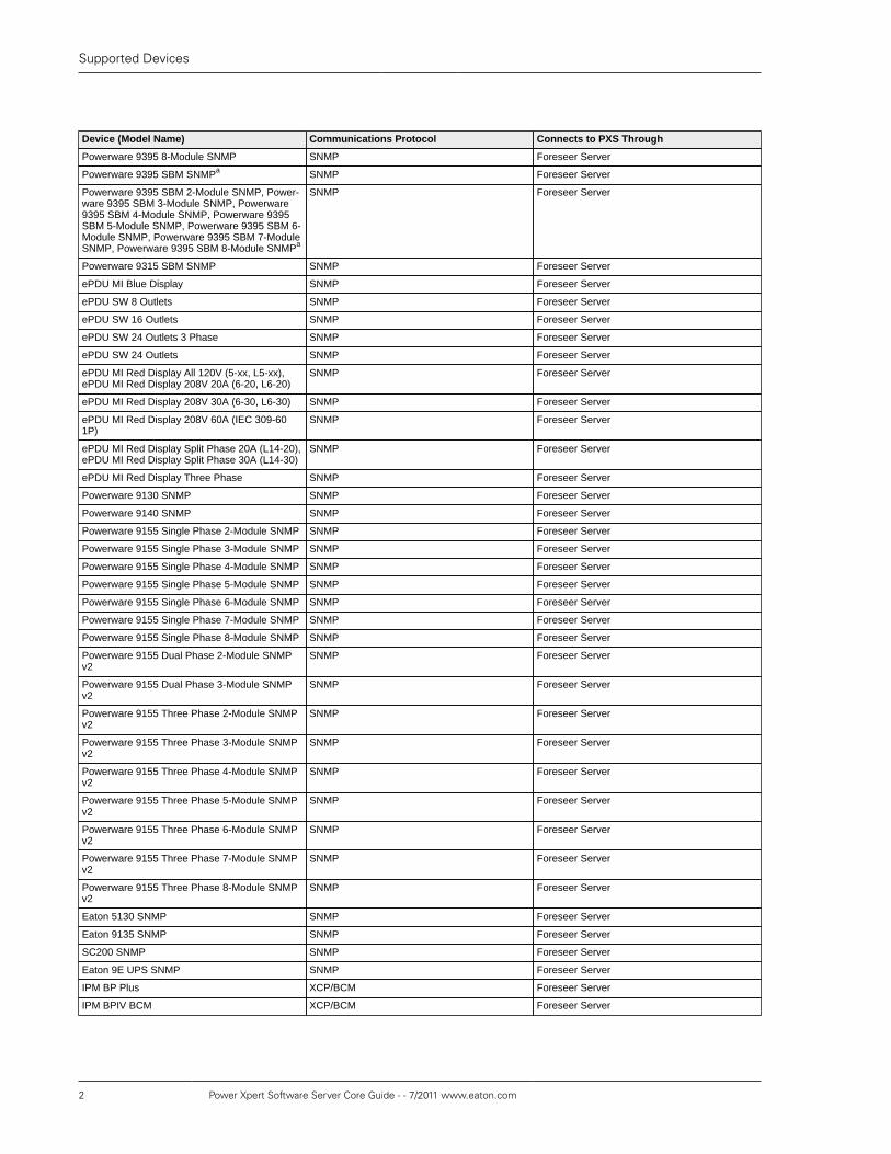
Connecting�DevicesSupported�Devices
The Power Xpert Software (PXS) Server Core software can monitor a wide range ofEaton and third party devices. How each device is connected will vary depending onthe type of device. You can determine how to install a device in PXS through the fol-lowing connection list. Each entry in the “Connects to PXS Through” column is hyper-linked to the instructions concerning how to connect that type of device. Click the en-try in the table to jump to the appropriate instructions for that device.
Table 1. Eaton Device Connection List
Device (Model Name) Communications Protocol Connects to PXS Through
Powerware 5115 SNMP SNMP Foreseer Server
Powerware 5125 SNMP SNMP Foreseer Server
Powerware 9120 SNMP SNMP Foreseer Server
Powerware 9125 SNMP SNMP Foreseer Server
Powerware 9170 Plus Dual Phase SNMP SNMP Foreseer Server
Powerware 9170 Plus SNMP SNMP Foreseer Server
Powerware 9155 SNMP SNMP Foreseer Server
Powerware 9155 Dual Phase SNMP SNMP Foreseer Server
Powerware 9155 3 Phase SNMP SNMP Foreseer Server
Powerware 9330 SNMP SNMP Foreseer Server
Powerware 9355 SNMP SNMP Foreseer Server
Powerware 9390 SNMP SNMP Foreseer Server
Powerware Prestige SNMP SNMP Foreseer Server
Powerware Ferrups SNMP SNMP Foreseer Server
Powerware LanSafe SNMP Agent SNMP Foreseer Server
Powerware 9315 50-500 SNMP SNMP Foreseer Server
Powerware 9315 750 SNMP SNMP Foreseer Server
Powerware 9305 SNMP SNMP Foreseer Server
Powerware BladeUPS SNMP SNMP Foreseer Server
Powerware BladeUPS Module SNMP SNMP Foreseer Server
Powerware BladeUPS 2-Module SNMP SNMP Foreseer Server
Powerware BladeUPS 3-Module SNMP SNMP Foreseer Server
Powerware BladeUPS 4-Module SNMP SNMP Foreseer Server
Powerware BladeUPS 5-Module SNMP SNMP Foreseer Server
Powerware BladeUPS 6-Module SNMP SNMP Foreseer Server
Powerware 9395 SNMP SNMP Foreseer Server
Powerware 9390 2-Module SNMP SNMP Foreseer Server
Powerware 9390 3-Module SNMP SNMP Foreseer Server
Powerware 9390 4-Module SNMP SNMP Foreseer Server
Powerware 9395 2-Module SNMP SNMP Foreseer Server
Powerware 9395 3-Module SNMP SNMP Foreseer Server
Powerware 9395 4-Module SNMP SNMP Foreseer Server
Powerware 9395 5-Module SNMP SNMP Foreseer Server
Powerware 9395 6-Module SNMP SNMP Foreseer Server
Powerware 9395 7-Module SNMP SNMP Foreseer Server
Supported Devices
2 Power Xpert Software Server Core Guide - - 7/2011 www.eaton.com
Device (Model Name) Communications Protocol Connects to PXS Through
Powerware 9395 8-Module SNMP SNMP Foreseer Server
Powerware 9395 SBM SNMPa SNMP Foreseer Server
Powerware 9395 SBM 2-Module SNMP, Power-ware 9395 SBM 3-Module SNMP, Powerware9395 SBM 4-Module SNMP, Powerware 9395SBM 5-Module SNMP, Powerware 9395 SBM 6-Module SNMP, Powerware 9395 SBM 7-ModuleSNMP, Powerware 9395 SBM 8-Module SNMPa
SNMP Foreseer Server
Powerware 9315 SBM SNMP SNMP Foreseer Server
ePDU MI Blue Display SNMP Foreseer Server
ePDU SW 8 Outlets SNMP Foreseer Server
ePDU SW 16 Outlets SNMP Foreseer Server
ePDU SW 24 Outlets 3 Phase SNMP Foreseer Server
ePDU SW 24 Outlets SNMP Foreseer Server
ePDU MI Red Display All 120V (5-xx, L5-xx),ePDU MI Red Display 208V 20A (6-20, L6-20)
SNMP Foreseer Server
ePDU MI Red Display 208V 30A (6-30, L6-30) SNMP Foreseer Server
ePDU MI Red Display 208V 60A (IEC 309-601P)
SNMP Foreseer Server
ePDU MI Red Display Split Phase 20A (L14-20),ePDU MI Red Display Split Phase 30A (L14-30)
SNMP Foreseer Server
ePDU MI Red Display Three Phase SNMP Foreseer Server
Powerware 9130 SNMP SNMP Foreseer Server
Powerware 9140 SNMP SNMP Foreseer Server
Powerware 9155 Single Phase 2-Module SNMP SNMP Foreseer Server
Powerware 9155 Single Phase 3-Module SNMP SNMP Foreseer Server
Powerware 9155 Single Phase 4-Module SNMP SNMP Foreseer Server
Powerware 9155 Single Phase 5-Module SNMP SNMP Foreseer Server
Powerware 9155 Single Phase 6-Module SNMP SNMP Foreseer Server
Powerware 9155 Single Phase 7-Module SNMP SNMP Foreseer Server
Powerware 9155 Single Phase 8-Module SNMP SNMP Foreseer Server
Powerware 9155 Dual Phase 2-Module SNMPv2
SNMP Foreseer Server
Powerware 9155 Dual Phase 3-Module SNMPv2
SNMP Foreseer Server
Powerware 9155 Three Phase 2-Module SNMPv2
SNMP Foreseer Server
Powerware 9155 Three Phase 3-Module SNMPv2
SNMP Foreseer Server
Powerware 9155 Three Phase 4-Module SNMPv2
SNMP Foreseer Server
Powerware 9155 Three Phase 5-Module SNMPv2
SNMP Foreseer Server
Powerware 9155 Three Phase 6-Module SNMPv2
SNMP Foreseer Server
Powerware 9155 Three Phase 7-Module SNMPv2
SNMP Foreseer Server
Powerware 9155 Three Phase 8-Module SNMPv2
SNMP Foreseer Server
Eaton 5130 SNMP SNMP Foreseer Server
Eaton 9135 SNMP SNMP Foreseer Server
SC200 SNMP SNMP Foreseer Server
Eaton 9E UPS SNMP SNMP Foreseer Server
IPM BP Plus XCP/BCM Foreseer Server
IPM BPIV BCM XCP/BCM Foreseer Server

Supported Devices
Power Xpert Software Server Core Guide - - 7/2011 www.eaton.com 3
Device (Model Name) Communications Protocol Connects to PXS Through
IPM BPIII BCM XCP/BCM Foreseer Server
IPM BPII Single Phase XCP/BCM Foreseer Server
IPM BPII 3 Phase XCP/BCM Foreseer Server
Powerware 9120 XCP XCP/BCM Foreseer Server
Powerware 9125 XCP XCP/BCM Foreseer Server
Powerware 9150 HV BCM XCP/BCM Foreseer Server
Powerware 9150 HV 3 Phase BCM XCP/BCM Foreseer Server
Powerware 9150 LV BCM XCP/BCM Foreseer Server
Powerware 9170 Plus Dual Phase XCP XCP/BCM Foreseer Server
Powerware 9170 Plus XCP XCP/BCM Foreseer Server
Powerware 9305 Network BCM XCP/BCM Foreseer Server
Powerware 9305 Serial UCII XCP/BCM Foreseer Server
Powerware 9320 XCP XCP/BCM Foreseer Server
Powerware 9330 XCP XCP/BCM Foreseer Server
Powerware 9335 XCP XCP/BCM Foreseer Server
Powerware 9340 XCP XCP/BCM Foreseer Server
Powerware Plus 18-36 BCM XCP/BCM Foreseer Server
Powerware Prestige BCM XCP/BCM Foreseer Server
Powerware Plus 750 BCM XCP/BCM Foreseer Server
Powerware Plus 40-500 BCM XCP/BCM Foreseer Server
System Channels, PowerVision System Chan-nels, Foreseer System Channels
Foreseer Server
Foreseer DAT Modbus TCP Modbus Foreseer Server
EATON EMS-PDU, EATON EMS-RPP, EATONEMS-PDR, EATON EMS-UGK
XCP PXGXb
PDU Panel, PDU Subfeed, EMS Panel, EMSSubfeed
XCP PXGXb
EATON EMS-RPM XCP PXGXb
EATON EMS-UGK Single Input, EATON EMS-PDR Single Input, EATON EMS-RPP Single In-put
XCP PXGX
EATON EMS-RPM Single Input XCP PXGX
EATON EMS-PDR Dual Input, EATON EMS-UGK Dual Input, EATON EMS-RPP Dual Input
a PXGXb
9155 XCP PXGXb
9155 Dual Phase WS PXGXb
9155 Three Phase WS PXGXb
9315 UPM without Bypass, 9315-750 UPM with-out Bypass
WS PXGXb
9315 UPM with Bypass, 9315-750 UPM with By-pass
WS PXGXb
9355 WS PXGXb
9390 WS PXGXb
9395 Single UPS without SBM, 9395 SingleUPS with SBM, 9395 Distributed Single UPSwithout SBM, 9395 Distributed Single UPS withSBM
WS PXGXb
9395 Internal Redundant without SBM, 9395 In-ternal Redundant with SBM, 9395 Distributed In-ternal Redundant without SBM, 9395 DistributedInternal Redundant with SBM
WS PXGXb
9395 Internal Redundant CB without SBM, 9395Internal Redundant CB with SBM, 9395 Dis-tributed Internal Redundant CB without SBM,
WS PXGXb

Supported Devices
4 Power Xpert Software Server Core Guide - - 7/2011 www.eaton.com
Device (Model Name) Communications Protocol Connects to PXS Through9395 Distributed Internal Redundant CB withSBM
9395 Distributed Parallel with SBM WS PXGXb
9315 SBM without MBP, 9315-750 SBM withoutMBP
WS PXGXb
9315 SBM with MBP, 9315-750 SBM with MBP WS PXGXb
BladeUPS WS PXGXb
Parallel BladeUPS WS PXGXb
Parallel BladeUPS Module WS PXGXb
IQ Analyzer, IQ Analyzer 6000/6200 INCOM PowerNet Server, PXGc
IQ Analyzer 6400/6600 INCOM PowerNet Server, PXGc
IQ DP-4000 INCOM PowerNet Server, PXGc
IQ Multipoint ESII INCOM PowerNet Server
Meter Point INCOM PowerNet Server
IQ MESII INCOM PXGc
IQ MESII Meter Point INCOM PXG
IQ Sentinel, Univ. w/External CTs, Univ. MultipleWell-head, Univ. Single Well-head
INCOM PowerNet Server, PXGc
Power Sentinel, IQ Power Sentinel INCOM PowerNet Server, PXGc
IQ7000 Modbus PowerNet Server
Pwr Mgr., Pwr Mgr. w/Inp. Trans. INCOM PowerNet Server, PXGc
Transducer(s), Transducer/Load Control INCOM PowerNet Server, PXGc
Load Control INCOM PowerNet Server, PXGc
IQ Multipoint ES INCOM PowerNet Server
Current Sensor INCOM PowerNet Server
IQ200/IQ300, IQ230/IQ330, IQ220/IQ320 INCOM PowerNet ServerPXGc
IQ230M/IQ330M (3wire), IQ230M/IQ330M(4wire), IQ230M/IQ330M
Modbus PowerNet Server, PXGc
IQ Data, IQ Generator INCOM PowerNet Server,PXG c
IQ DataPlus, IQ DataPlusII, IQ DataPlusII Gold-star, IQ DataPlusII HV
INCOM PowerNet Server, PXGc
IQ 1000 INCOM PowerNet Server
IQ 1000II, IQ 1000II Goldstar INCOM PowerNet Server
IQ-500 INCOM PowerNet Server, PXGc
FP4000/FP5000, FP-5000, FP5000, FP4000 INCOM PowerNet Server, PXGc
MP-3000, MP-4000 INCOM PowerNet Server, PXGc
Digitrip MV, Digitrip 3000, Digitrip 3200 INCOM PowerNet Server, PXGc
RTD Module, Universal RTD Module INCOM PowerNet Server, PXGc
MMCO Relay INCOM PowerNet Server
MPCV Relay INCOM PowerNet Server, PXGc, Vaultgard
Accutrol 400 INCOM PowerNet Server, PXGc
AF97 INCOM PowerNet Server, PXGc
Advantage INCOM PowerNet Server, PXGc
Advantage Control INCOM PowerNet Server
ACM/Advantage INCOM PowerNet Server, PXGc
Alarm Relay INCOM PowerNet Server
Addressable Relay, Addressable Relay Inv. INCOM PowerNet Server
IQ Transfer Switch, IQ Transfer Switch/ II,ATC-600, ATC-800
INCOM PowerNet Server, PXGc
ATC-400 INCOM PowerNet Server, PXGc
Digitrip 700/800 INCOM PowerNet Server

Supported Devices
Power Xpert Software Server Core Guide - - 7/2011 www.eaton.com 5
Device (Model Name) Communications Protocol Connects to PXS Through
Digitrip 810 INCOM PowerNet Server, PXGc
Digitrip 910 INCOM PowerNet Server, PXGc
DT1150/DT1150V, DT1150/DT1150V/Navy, Dig-itrip 1150/1150V, Digitrip 1150 Comm Ver 0,Digitrip 1150/1150V Comm Ver 1
INCOM PowerNet Server, PXGc
Digitrip 520MC INCOM PowerNet Server, PXGc
Digitrip Optim 550, Digitrip Optim 750 INCOM PowerNet Server, PXGc
Digitrip Optim 1050 INCOM PowerNet Server, PXGc
Digital Input Module, DIM Digital Input Module INCOM PowerNet Server, PXGc, VaultGard
KYZ Input, Pulse Input INCOM PowerNet Server, PXGc
Digital Input Module KYZ Inputs INCOM PXG
AIM INCOM PowerNet Server
Btu Net, Btu Forward, Btu Reverse INCOM PowerNet Server
General Purpose INCOM PowerNet Server
Pulse Counter INCOM PowerNet Server
Runtime INCOM PowerNet Server
Pow-R-Command INCOM PowerNet Server
Data Logging (DLC) INCOM PowerNet Server
Daylight Optimizer (DOC) INCOM PowerNet Server
Switch Override (SOC) INCOM PowerNet Server
Telephone Override (TOC) INCOM PowerNet Server
Breaker Controller INCOM PowerNet Server
BIM/BIMII INCOM PowerNet Server, PXGc
IQ CED INCOM PowerNet Server, PXGc
AEM, AEMII INCOM PowerNet Server, PXGc
CMU INCOM PowerNet Server, PXGc
Series NRX 520M, Series NRX 520 INCOM PowerNet Server, PXGc, ECAM
Series NRX 1150, NRX 1150 Trip Unit INCOM PowerNet Server, ECAM
FP6000 INCOM PXGc
FP-6000 INCOM PowerNet Server
ARMS IDM INCOM VaultGardd
PM3 INCOM PowerNet Server
PM3 Breaker INCOM PowerNet Server
PowerXpert Meter (PX4051, PX4251, PX4054,PX4254, PX6051, PX6251, PX6054, PX6454,PX8051, PX8251, PX8054, PX8254, PXM4051,PXM4251, PXM4054, PXM4254, PXM6051,PXM6251, PXM6054, PXM6454, PXM8051,PXM8251, PXM8054, PXM8254)
BacnetWS+ PXS Configuration Manager (direct connection)
PXM2250, PXM2260, PXM2270, PXM2280,PXM2290
BacnetWS+ PXS Configuration Manager (direct connection)
IQ250, IQ260 Modbus PXGc
IQ130 Modbus PXGc
IQ140 Modbus PXGc
IQ150 Modbus PXGc
IQ35M Modbus PXGc
Wireless Current Sensor INCOM VaultGardd
Wireless Temperature Sensor INCOM VaultGardd
C441 Motor Insight Overload Relay Modbus PXGc
EDR-3000 Modbus PXGc
EDR-4000 Modbus PXGc
ETR-4000 Modbus PXGc

Device Categories
6 Power Xpert Software Server Core Guide - - 7/2011 www.eaton.com
Device (Model Name) Communications Protocol Connects to PXS Through
InsulGard Modbus PXGc
IT S811 (MV811) QCPort PXGc
IT Starter Cover Control QCPort PXGc
IT Starter QSNAP QCPort PXGc
aSupport pending (user interface support has been implemented in PXS, however communication support for all SBM configurations arepending verification with a future 9395 UPS firmware version release)bWhen the PXGX is installed in PXS, all of its attached devices are also installed.cWhen the PXG is installed, all of its attached devices are also installed.dWhen the VaultGard is installed, all of its attached devices are also installed.
Table 2. Third-party Device Connection List
Device Communications Protocol Connects to PXS Through
ABB TPU 2000 Modbus PXG c
GE 369 Motor Relay Modbus PXG c
GE 469 Motor Relay Modbus PXG c
PML 7350 Meter Series Modbus PXG c
PML 7550 Meter Series Modbus PXG c
PML 7650 Meter Series Modbus PXG c
Power Xpert Gateway 3rd Party Device Support Modbus PXG c
Square D CM3000 Meter Series Modbus PXG c
Square D CM4000/4250 Meter Series Modbus PXG c
Square D PM710 Meter Series Modbus PXG c
Square D PM810/820/850/870 Meter Series Modbus PXG c
Device�Categories
The devices fall into one of three categories:
1. Devices that communicate directly with the Power Xpert Server Core. Examplesof this type of device are the Power Xpert Gateway and the Power Xpert MeterCommunications Card. Also included in this category is connecting to a remotePowerNet system.
In the Device Connection Lists, some of the devices are listed as connectingto PXS via a PXG, PXGX, or VaultGard. When a PXG, PXGX, or VaultGard isadded to PXS, all of its connected devices are also automatically added.
2. Devices that communicate with Power Xpert Server Core via PowerNet Software.PowerNet is a component of Power Xpert Server Core and must be installed priorto connecting a device. Typical devices in this category are devices that commu-nicate via Cutler Hammer communication devices such as: NetLink, EMINT andMINT II.
In some cases in the Device Connection Lists, devices are listed as connectingwith PXS either through PowerNet or through a PXG or PXGX. Either method willwork.
Note
The PowerNet Domain Servers and Device Servers must be in the sametime zone as the Power Xpert Server Core software.
3. Devices that communicate with the Power Xpert Server Core Software via Fore-seer software. Foreseer is a component of Power Xpert Server Core and is in-

Connecting Devices Directly to Power Xpert ServerCore
Power Xpert Software Server Core Guide - - 7/2011 www.eaton.com 7
stalled automatically when Power Xpert Server Core is installed. Devices that fitinto this category communicate via a PowerWare Web/SNMP Card. These aregenerally UPSs. Other devices that communicate via Foreseer are third partyproducts that communicate via SNMP or Modbus TCP.
Connecting�Devices�Directly�to�Power�Xpert�Server�Core
Important
Before connecting a Power Xpert Meter, Power Xpert Gateway, or other PowerXpert architecture device to PXS, ensure that the device is using a static IP ad-dress. If the device uses a dynamically assigned IP address and that addresschanges, PXS will lose the connection to that device.
Make sure that the device name does not exceed 40 characters. If the devicename is longer, PXS won't display the device summary page associated withthat device.
Note
Refer to the section called “Establishing Secure Communications BetweenPXS and Power Expert Architecture Devices” [12] before installing the de-vice if you intend to communicate to the device via SSL. Before connecting,you must first import and install the certificate from each device on the PXSserver machine. You must also enable SSL when installing each device.
To connect devices that communicate directly with the Power Xpert Server Core,use the Power Xpert Configuration Manager. To access the Configuration Man-ager through the Windows Start menu, select All Programs>Eaton Power XpertSoftware>Configuration Manager.
To add a server or device:
1. The main Configuration Manager screen will open.
2. Right-click Networks to add a server/device.

Connecting Devices Directly to Power Xpert ServerCore
8 Power Xpert Software Server Core Guide - - 7/2011 www.eaton.com
3. The first Add Server or Device wizard dialog box will appear. If you wish to con-nect to a Foreseer Server or other Power Xpert enabled device, select BAC-netWSplus Server/device (such as Power Xpert Gateway…) and click Next.
4. Enter the various properties, depending on your device configuration, in the ap-propriate fields. Refer to your device documentation and any configuration notesfrom its installation for these values. If you will be using SSL, make sure that youread through the information in the section called “Establishing Secure Commu-nications Between PXS and Power Expert Architecture Devices” [12].

Connecting Devices Directly to Power Xpert ServerCore
Power Xpert Software Server Core Guide - - 7/2011 www.eaton.com 9
5. After entering the IP address, you can test for the presence of the device on yournetwork by clicking the Ping Server button. If the device responds, you’ll see thefollowing information box.
6. You can test the communications parameters, log-in, etc. with the Test WebService button. If the test completes successfully, you’ll see the following infor-mation box.

Connecting Devices Directly to Power Xpert ServerCore
10 Power Xpert Software Server Core Guide - - 7/2011 www.eaton.com
7. Once you have verified that Power Xpert Software is communicating properlywith the device, click the Next button.
8. Retrieve the name of the device and, if necessary, modify the name. Click Next.
9. Verify that your information is correct. If it is correct, click OK.

Connecting Devices Directly to Power Xpert ServerCore
Power Xpert Software Server Core Guide - - 7/2011 www.eaton.com 11
10. The new device is added to the tree.
11. If you wish to rename a device or server:
a. Right-click the device name in the tree.
b. Select Rename.
c. Type the desired name for the server/device.
12. If you need to connect to PowerNet, follow the steps in the next section. If not,select Save from the File menu or click the disk icon. Upon closing, you will beprompted to restart the service.

Establishing Secure Communications Between PXSand Power Expert Architecture Devices
12 Power Xpert Software Server Core Guide - - 7/2011 www.eaton.com
13. The Power Xpert service must be restarted for the connections to be “discov-
ered.” Use the gear icon in the Power Xpert Toolbar to accomplish this.
14. The following screen will be displayed. Choose the appropriate machine andthen click OK.
Establishing�Secure�Communications�Between�PXS�and�Power�Expert�ArchitectureDevices
There are two scenarios for securing communications:
• PXS to the Power Xpert architecture device. This is easy to implement: just importthe digital certificate used by the device onto the PXS server machine.
• Power Xpert architecture device to PXS. This requires that you import a digital cer-tificate into both IIS running on the PXS server machine and into the Power Ex-pert architecture device. When importing the digital certificate to the PXS servermachine, make sure that you import it into the same account used to run the PXSWindows service. Eaton recommends using a domain account for the PXS service.Also, there may not be a mechanism on the device to import a digital certificate, soinstead you can implement this by enabling SSL but ignoring the certificate. Referto the documentation with your device for instructions on enabling SSL.
• Instructions for enabling SSL on PXS may be found in the section called “Connect-ing Devices Directly to Power Xpert Server Core” [7].
Remaining security considerations: If a user ID and password are required bya device, PXS can provide these. However, they are passed as a digest. While notplain text, a digest can be deciphered.
For detailed information concerning certificate installation in Server 2003 and assign-ing a certificate to a website, follow this link: http://support.microsoft.com/kb/816794

Connecting to a PowerNet Domain Server andEaton Network Translators
Power Xpert Software Server Core Guide - - 7/2011 www.eaton.com 13
For detailed information concerning certificate installation in Server 2008 R2, followthis link: http://technet.microsoft.com/en-us/library/cc501466.aspx
Connecting�to�a�PowerNet�Domain�Server�and�Eaton�Network�Translators
Important
PXS can only connect to a single instance of PowerNet.
This section provides the basic steps for connecting a device that communicates viathe PowerNet component to the Power Xpert Server Core.
To connect to an existing PowerNet System first verify that the existing system,whether running local or remote, is at least v.3.32 or higher. If not, install the upgradeversion found on the Power Xpert DVD.
Preparing�to�Connect�to�a�Remote�PowerNet�Computer
Power Xpert Software can connect to a PowerNet installation running on a differentcomputer. Use this procedure to prepare Power Xpert Software to acquire data froma remote PowerNet system.
To Prepare the PowerNet computer
1. Ensure the computer’s firewall, if any, is turned off. Alternatively, your IT adminis-trator can enable the ports used for Windows file sharing and MSDE.
2. If the computer is running Windows XP, ensure simple file sharing is turned off:
a. From the Tools menu in Windows Explorer, click Folder Options.
b. From the View tab, clear the Use simple file sharing check box.
3. Create an account for access to PowerNet. If the computers are members of thesame domain, you can ask your IT administrator to create a domain account. Oth-erwise, create a local account:
a. From the Windows Start menu, right-click My Computer and select Manage.
b. Navigate to Users in Local Users and Groups.
c. From the Action menu, click New User.
d. Enter a username (PowerXpert is recommended) and a strong password.
e. Clear the User must change password at next logon check box.
f. Click Create and then Close.
4. Add the PowerXpert (or whatever user name you chose) user to the Adminis-trators group. Alternatively, your IT administrator can grant the PowerXpert ac-count write access to the PowerNet folder (see the next step) and PowerNet SQLdatabase.
a. Double-click the PowerXpert account.
b. Click the Member Of tab.
c. Click Add.

Troubleshooting the Connection with a RemotePowerNet System
14 Power Xpert Software Server Core Guide - - 7/2011 www.eaton.com
d. Type Administrators.
e. Click Check Names.
f. Click OK.
5. Share the folder containing the PowerNet database:
a. From Windows Explorer, navigate to the PowerNet database folder. Bydefault for PowerNet 3.34 and later, this is C:\Program Files\PowerXpert Software\PowerNet\Database. For earlier versions, this is C:\PowerNet\Database.
b. Share this folder with the share name _PnetDB.
c. Click Permissions to edit the share permissions.
d. Remove Everyone.
e. Add the PowerXpert account, and give it Change permission.
To prepare the Power Xpert Software computer
1. Ensure the computer’s firewall, if any, is turned off. Alternatively, your IT adminis-trator can enable the ports used for Windows file sharing and MSDE.
2. Install Power Xpert Software.
3. If you created a PowerXpert account on the PowerNet computer, create an iden-tical account (same username and password).
4. Add the PowerXpert account to the Administrators group. This account shouldgrant PowerNet SysAdmin rights.
5. Set the Power Xpert Software service to use the PowerXpert account:
a. From the Start menu, right click My Computer and select Manage.
b. Navigate to Services under Services and Applications.
c. Right-click Power Xpert Software and then click Properties.
d. From the Log On tab, chose the This account radio button and type thePowerXpert account username and password.
6. Log into Windows using the PowerXpert account.
7. Using the Power Xpert Configuration Manager, add a PowerNet server, and enterthe name of your remote PowerNet computer (see the section called “Connectingto an Existing PowerNet System (local or remote) ” [15] for more details).
Troubleshooting�the�Connection�with�a�Remote�PowerNet�System
The following is an independent test of the connection.
If you are having difficulty establishing the connection, manually verify that theremote database file is accessible:
1. Log into Windows using the PowerXpert account.

Connecting to an Existing PowerNet System (localor remote)
Power Xpert Software Server Core Guide - - 7/2011 www.eaton.com 15
2. From the Windows Start menu, click Run.
3. Type the following and then press Enter.
\\RemoteComputerName\_PnetDB
4. A Windows Explorer window will open, showing the contents of the PowerNetdatabase folder.
5. Select File > New > Text Document and create a new file, such as Test1.
6. If you get an error, consult your IT support staff to determine the source of theproblem, as this file share connection is independent of Power Xpert Software.
The following lists symptoms of common problems and likely causes:
“Can’t find network path” error: A firewall enabled and necessary ports areblocked.
Prompt to enter a username and password. There is no account on the Pow-erNet computer that matches (same username and password) the interactive ac-count of the Power Xpert computer. Perhaps no account was created on the Power-Net computer, or on the Power Xpert computer, and you are not logged into a match-ing account.
Prompt for a password for the username “Guest”. On the PowerNet computer,simple file sharing has not been turned off.
Connecting�to�an�Existing�PowerNet�System�(local�or�remote)
To begin, open the Configuration Manager, either through the Windows Start menuor from the Power Xpert Software Web Application. To start the ConfigurationManager from the Web Application, start-up Power Xpert Software from Start>AllPrograms>Eaton Power Xpert Software>Web Application in the Windows Startmenu.
1. In the Configuration menu, choose Configuration Manager.
2. When opening the Configuration Manger from the Web Application, it is alreadyconnected to Power Xpert Software.

Connecting to an Existing PowerNet System (localor remote)
16 Power Xpert Software Server Core Guide - - 7/2011 www.eaton.com
3. Right-click Networks and select Add Server/Device.
4. Select PowerNet Server and click Next.
5. Select PowerNet installed on a different computer than Power Xpert Software.Enter the exact path for the computer and database folder. You can also use thebrowse button at the right to look for the computer.
Note
When configuring PowerNet on a different computer the following set-tings must be in place:
• An identical username and password with Administrative privileges must re-side on both the Power Xpert Software Server Core computer and the Power-Net computer.
• The Eaton Power Xpert Software service must use the identical username andpassword as the Power Xpert Software Server Core and PowerNet.

Connecting to an Existing PowerNet System (localor remote)
Power Xpert Software Server Core Guide - - 7/2011 www.eaton.com 17
• If the Windows Firewall is enabled, the necessary ports must be opened onthe PowerNet machine for IGSP, file/printer sharing and SQL Server.
6. Next, use the buttons provided to test the configuration and the SQL server. Dia-log boxes like those below will be displayed.

Connecting to an Existing PowerNet System (localor remote)
18 Power Xpert Software Server Core Guide - - 7/2011 www.eaton.com
7. Click OK and then Next.
8. You may type a new name for the server or use the default name.
9. Click Next and review the information. If correct, click OK.
10. The new server is added to the tree. This name may be changed by right-clickingit and replacing the text with a new name.
11. The PowerNet connection is now complete. Now that the connection is complete,you must save the configuration.
12. The Power Xpert service must be restarted for the connections to be “discov-
ered.” Use the gear icon in the Power Xpert Toolbar to accomplish this.The following screen will be displayed. Choose the appropriate machine andclick OK.

Connecting to Cutler-Hammer Network Translatorsthrough PowerNet
Power Xpert Software Server Core Guide - - 7/2011 www.eaton.com 19
Connecting�to�Cutler-Hammer�Network�Translators�through�PowerNet
The Cutler-Hammer power monitoring system consists of four major components.
Domain Server: Houses the database that describes the entire systemand is used to configure the Device Server.
Device Server: Gathers information from devices via the INCOMtranslator(s)
INCOM Translator: Converts INCOM (the language devices speak) to TCP/IP
INCOM Device: FP-5000s, IQ Analyzer 6400, other meters, trip units,etc.

Overview of the Connection Process
20 Power Xpert Software Server Core Guide - - 7/2011 www.eaton.com
Figure 1. A typical installation
Note
The PowerNet Domain Servers and Device Servers must be in the sametime zone as the Power Xpert Server Core software.
Overview�of�the�Connection�Process
There are several configuration modes which may be used. This section deals withthe On-line configuration mode. Other modes (On-line view only, Off-line and Off-lineview only) are described in Chapter 6 of the PowerNet User’s Guide.
There are four basic steps in the configuration process:
1. Connecting a Device Server to a Domain Server
2. Connecting a Device Communications Network Interface (Translator) to a DeviceServer
3. Connecting a Device to a Network Translator
4. Connecting a PowerNet Domain Server to the Power Xpert Software
Connecting�a�Device�Server�to�a�Domain�Server
To connect a Device Server to a Domain Server
1. Launch the PowerNet Configurator application from the Windows Start menu asfollows: Eaton Power Xpert Software>PowerNet Suite>Configurator.
Note
it is assumed that this is a new installation of PowerNet. For existing in-stallations, please see the PowerNet User’s Guide.

Overview of the Connection Process
Power Xpert Software Server Core Guide - - 7/2011 www.eaton.com 21
2. The login screen is displayed. Type ADMIN for both the PowerNet User ID andthe Password. Click OK.
3. The PowerNet Configurator main screen will be displayed. Click OK to begin.
4. Click the System drop-down menu and select the Security Manager.

Overview of the Connection Process
22 Power Xpert Software Server Core Guide - - 7/2011 www.eaton.com
5. The main screen of Security Manager is displayed. Select Add (under the De-vice Server column).
6. The Add DeviceServer Data dialog box is displayed.
7. Type the name for your Device Server. Select the Local option and the local IPAddress will automatically be filled in (because in this configuration, we are work-ing with the Device Server located on the same machine). If the Device Serveris on another machine or a NetLink, leave the Remote option selected and enterthe IP Address of the Device Server. Then click OK.

Overview of the Connection Process
Power Xpert Software Server Core Guide - - 7/2011 www.eaton.com 23
8. The device server has now been added to the security manager. Click Close tocomplete this step.
9. The main Configurator Screen is displayed. Note that Device Server appears inthe Network Interface list.

Overview of the Connection Process
24 Power Xpert Software Server Core Guide - - 7/2011 www.eaton.com
10. Add the Device Server to the Network Tree by dragging it from the Network In-terface list box onto the space below Network Tree.

Overview of the Connection Process
Power Xpert Software Server Core Guide - - 7/2011 www.eaton.com 25
11. The main configuration screen appears on the far right in the details window. Itmay be necessary to scroll to the far right depending on the display settings onthe computer. Select Add.
Note
If security has previously been added to the Device Server in the Secu-rity Manager, a Device Server list box will appear first from which to se-lect the desired Device Server.
12. The screen below is displayed. Note that there is a green icon that accompaniesthe Device Server. This means that the Device Server is within your Domain.

Connecting a Device Communications Network In-terface (Translator)
26 Power Xpert Software Server Core Guide - - 7/2011 www.eaton.com
Device Server connection is now complete.
Connecting�a�Device�Communications�Network�Interface�(Translator)
There are several methods/translators available to provide communication betweena Device Server and a Cutler Hammer device(s). This section will cover the followingmethods/translators:
• Com Port Direct: MINT, RS-232 PONI and PRC MINT
• EPONI
• EMINT
Connecting�via�COM�Port�Direct
The COM Port Direct connection allows you to communicate with a device networkthrough a Device Server’s serial port via INCOM RS-232 protocol. To do this oneof the following translators must be used: MINT, RS-232 PONI, or PRC MINT. TheMINT, RS-232 PONI and PRC MINT are the communication hardware through whichinformation is routed from the network to the DeviceServer. PowerNet also can com-municate with the network via the Modbus RTU protocol.
To begin, the COM port must be configured to the same settings as the communica-tion hardware.
To configure COM Port Direct, complete the following steps in the main windowof Configurator:
1. Click-and-drag the COM Port Direct from the Network Interface list box to theNetwork Tree, dropping it when the mouse pointer highlights the DeviceServer.
The Network Tree will be displayed, but the Tree and list boxes will be inactive(grayed out).

Connecting a Device Communications Network In-terface (Translator)
Power Xpert Software Server Core Guide - - 7/2011 www.eaton.com 27
The INCOM (RS232) and Modbus RTU buttons in this window may display withgreen or red text.
• After selecting a COM Port type button, the button’s text turns green, indicatingthat the selected type is now the active protocol. The devices listed in the Sub-network Master and Device list boxes display the devices supported by theselected protocol.
• If a button displays red text, that protocol type is deselected or inactive.
• You can select either button at any time until the COM Port is configured. Oncethe COM Port is configured, the protocol button that is not selected becomesinactive (shaded gray) and cannot be selected.
2. Select a unique COM port number (1 to 32) in the ComPort # field.
3. Click INCOM (RS232) or Modbus RTU. The Config. Information dialog box dis-plays.

Connecting a Device Communications Network In-terface (Translator)
28 Power Xpert Software Server Core Guide - - 7/2011 www.eaton.com
Note
If you selected a Modbus protocol, the Use Ack/Nack field is inactive.
4. In the Protocol Type field, select MINT, RS232 PONI, PRC MINT, or ModbusRTU.
These protocols are described in the following table.
Protocol Description
MINT Permits multiple INCOM devices.
Communicates using the RS232 to INCOM protocol.protocol.
There are no device restrictions.
RS-232 PONI Permits a single INCOM device.
Communicates using the RS-232 to INCOM protocol.
Supports only one device.
PRC MINT Permits a single Pow-R-Command submaster.
Communicates using the RS-232 to PRC protocol.
Supports multiple panels.
Modbus RTU Permits multiple Modbus devices (such as the IQ230M/330M or IQ 7000).
Communicates using the Modbus protocol.
5. If there is a serial delay in communications between the Device Server and thedevice network attached to the CONI, MINT, RS-232 PONI, PRC MINT or Mod-bus RTU, you need to set the Time Extended field to the rate of the delay, in mil-liseconds.
If the delay is set too low, RX timeout errors occur and are recorded in the Pow-erNet Monitor application. Once devices are configured and the system hasbeen running the RX timeout errors can be viewed by going to the PowerNetMonitor and completing the following steps in its main window.
a. From the Device list, select the device.
b. From the Device menu, select Display INCOM Device Statistics.

Connecting a Device Communications Network In-terface (Translator)
Power Xpert Software Server Core Guide - - 7/2011 www.eaton.com 29
If RX Timeout errors are occurring for a device, increase the value of the TimeExtended field until the errors no longer occur.
Note
Be careful to select the minimum Time Extended that provides reliablecommunications. Choosing an inappropriately large value results in longcommunication delays if a network device is legitimately not responding(i.e., the device is off, or out of service).
6. In the Baud Rate field, select the baud rate for the particular communicationhardware that you have chosen.
The available baud rates for each are described in the following table.
Device Baud Rate
MINT 1,200, 2,400, 9,600, 19,200 baud
RS-232 PONI 1,200 baud only
PRC MINT 1,200, 2,400, 9,600, 19,200 baud
Modbus RTU 1,200, 2,400, 9,600, 19,200, 38,400, 57,600 and115,200 baud
7. In the Handshake field, set the handshake for the communications hardware us-es, if any.
8. From the Stop Bits section, select the appropriate stop bits value used by thecommunications hardware.
9. If the communications hardware uses Ack/Nack (Acknowledgement/No Acknowl-edgement), select the Use Ack/Nack check box.
10. Click the Enable polling check box to check or clear it, depending on whether youwant to start polling the device at the present time.
Note
Default values display for the Data Bits and Parity output fields. Be surethat your communication hardware is physically configured to these set-tings.
11. Click OK. The main window of Configurator re-displays with list boxes still inac-tive (grayed out).

Connecting a Device Communications Network In-terface (Translator)
30 Power Xpert Software Server Core Guide - - 7/2011 www.eaton.com
12. Click Add. The Network Tree displays the now configured COM Port Direct withan identifying prefix, Nx (where N designates this is a network, and x representsthe particular network number).
The Details Window displays the input settings for the COM Port Direct.

Connecting a Device Communications Network In-terface (Translator)
Power Xpert Software Server Core Guide - - 7/2011 www.eaton.com 31
Other translators may now be added or you may wish to skip to the section called“Connecting a Device” [34].
Connecting�an�EPONI�Group
An EPONI Group allows you to communicate over Ethernet with devices that eachhave an EPONI mounted to them. A Device Server can communicate with multipleEPONIs through the EPONI Group network interface. To connect an EPONI Group,complete the following steps in the main window of Configurator.
1. Click and drag EPONI Group from the Network Interface list box to the NetworkTree, dropping it when the mouse pointer highlights the DeviceServer.
The Network Tree displays, but the Tree and list boxes are inactive (grayed out).
2. In the Receive Timeout Extend box, enter a number between 0 and 60,000. Thisnumber indicates the number of milliseconds to be added to the TCP/IP timeoutfor each request that the DeviceServer is sending to the EPONI.
3. In the Transmit Delay Time box, select a number between 0 and 100. This num-ber indicates the number of milliseconds that each request in one request pack-et (sent from the DeviceServer to the EPONI) will be delayed after the sending ofthe request just previous to it.
4. In the Batch Timeout Multiplier, select a number between 1 and 10 (default is 4)where the Batch Timeout is the sum of all the timeouts set for a request packetsent by the DeviceServer to the EPONI, this number increases the Batch Time-out by the chosen multiple.

Connecting a Device Communications Network In-terface (Translator)
32 Power Xpert Software Server Core Guide - - 7/2011 www.eaton.com
Note
Batch Timeout takes place as follows. The EPONI proceeds througheach request in order and times out when the sum of the timeouts forthose individual requests equals the batch timeout.
5. Click the Enable Polling check box to check or clear it, depending on whetheryou want to start polling the device at the present time.
6. Click Add.
The Network Tree displays the configured EPONI with a prefix, Nx (where N desig-nates this is a network and x represents the particular network number).
The Details Window displays the input settings for the communication hardware.
You are now able to add devices to the DeviceServer. To add devices, see the thesection called “Connecting a Device” [34] for more information.
Connecting�an�EMINT
An EMINT (Ethernet Master Incom Network Translator) can be set up remotely fromthe DeviceServer. One EMINT allows the DeviceServer to communicate over Ether-net with a network of devices, up to as many devices as your DeviceServer licensesupports.
To connect an EMINT, complete the following steps in the main window of Configura-tor.
1. Click and drag EMINT from the Network Interface list box to the Network Tree,dropping it when the mouse pointer highlights the DeviceServer.
The Network Tree displays, but the Tree and the list boxes are inactive (grayedout).

Connecting a Device Communications Network In-terface (Translator)
Power Xpert Software Server Core Guide - - 7/2011 www.eaton.com 33
2. In the Details window, enter the valid and unique IP address for the EMINT.
3. In the TCP/IP Timeout box, enter the number of milliseconds (zero to billions)that you want the DeviceServer to wait (before timing out) for data to be returnedby the EMINT in response to a request packet.
4. In the Receive Timeout Extend box, enter a number between 0 and 60,000. Thisnumber indicates the number of milliseconds to be added to the TCP/IP timeoutfor each request in the packet of requests that the DeviceServer is sending to theEMINT.
5. In the Transmit Delay Time box, select a number between 0 and 100. This num-ber indicates the number of milliseconds of delay between each request in a re-quest packet sent from the DeviceServer to the EMINT.
6. In the Batch Timeout Multiplier field, select a number between 1 and 10 (defaultis 4). Where the Batch Timeout is the sum of all the timeouts set for a requestpacket sent by the DeviceServer to the EMINT, this number increases the BatchTimeout by the chosen multiple.
Note
Batch Timeout takes place as follows. The EMINT proceeds through eachrequest in order and times out when the sum of the timeouts for those indi-vidual requests equals the batch timeout.
1. Click the Enable Polling check box to check or clear it, depending on whetheryou want to start polling the device at the present time.
2. Click Add.
The Network Tree displays the configured EMINT with a prefix, Nx (where N desig-nates this is a network and x represents the particular network number).

Connecting a Device Communications Network In-terface (Translator)
34 Power Xpert Software Server Core Guide - - 7/2011 www.eaton.com
The Details Window displays the input settings for the communication hardware.
You are now able to add devices to the Device Server. See the section called “Con-necting a Device” [34].
Note
To modify or delete a Device Communication Network Interface such asa Com Port Direct Device, EPONI or EMINT, see Chapter 6 of the User’sGuide to PowerNet Software.
Connecting�a�Device
After the Device Server and a Device Communications Network Interface (Translator)have been connected, you are able to configure devices (including subnetwork mas-ters) to communicate on these networks.
Important
Make certain that the device name for any device does not exceed 40 charac-ters. If the device name exceeds 40 characters, PXS won't be able to display thedevice summary page for that device. If necessary, rename the device in Pow-erNet so that the name doesn't exceed 40 characters.
Certain INCOM devices cannot communicate with certain networks or subnetworkmasters. Configurator is automated such that once you have added a DeviceServ-er and a communication interface, the only INCOM devices that display in the Devicelist box are ones that can communicate with the set of selected items.
To connect a device, complete the following steps in the main window ofConfigurator:
1. On the Network Tree, click the Network Interface to which you want to add adevice.

Connecting a Device Communications Network In-terface (Translator)
Power Xpert Software Server Core Guide - - 7/2011 www.eaton.com 35
The devices that can be configured to that interface display in the Device list box.
2. Click and drag a Device from the Device list box to the Network Tree, dropping itwhen the mouse pointer highlights the appropriate device communication networkinterface.
The Network Tree displays the device, but the Tree and list boxes are inactive(grayed out).
The Details Window contains fields for settings to be entered for the device.
Note
If you attempt to attach a device to a network interface that cannot beconfigured with that device, an error message displays. Also note thatyou can only attach a single item to an RS-232 PONI.
3. In the Description field, type a description for the device.
4. In the Dev. Number field, either select a device number or allow Configurator toset the device number by default.
Note
Once you use a device number in a particular DeviceServer configura-tion, that number is removed from the Dev. Number field. The devicenumber becomes available again if you delete a device, or if you selectanother DeviceServer.
5. If the Network Interface field is enabled, select the correct interface.

Connecting a Device Communications Network In-terface (Translator)
36 Power Xpert Software Server Core Guide - - 7/2011 www.eaton.com
Note
The device may be wired to the device network, either directly or througha PONI.
6. Enter, or select, the correct address for the device in the Address field.
• If you are adding an AIM that was last used by Series III, a dialog box displays.
• If you are transferring an AIM configuration from Series III, click Continue. Asecond dialog box displays, detailing the steps necessary to finish the transfer.
• If you are adding an AIM for the first time, or want to overwrite the existing AIMconfiguration, click Cancel.
Note
If you are configuring the device on a subnetwork, the Address field auto-matically displays the allowable number of device addresses for the cor-responding subnetwork master. Note that the address corresponds to thedipswitch settings on the subnetwork master or at its interface (PONI orDirect), and must not be used by any other device.
7. Click Add.
The Network Tree displays the configured device with a prefix, Dx (where D des-ignates this is a device and x represents the particular device number).
The Details Window updates the input settings for the device; and when in On-Line mode, it displays the Status and Reason fields, which indicate the real-timestatus and status reason of the device.

Connecting a Local PowerNet Domain Server toPower Xpert
Power Xpert Software Server Core Guide - - 7/2011 www.eaton.com 37
Connecting�a�Local�PowerNet�Domain�Server�to�Power�Xpert
Now that the PowerNet Server has been configured and is part of the domain, it istime to connect to it with Power Xpert.
1. Open the Configuration Manager through either:
• Windows Start menu: All Programs>Eaton Power Xpert Software>Web Ap-plication.
• Within PXS: from the Configuration, choose Configuration Manager.
2. Right-click Networks to add a server.

Connecting a Local PowerNet Domain Server toPower Xpert
38 Power Xpert Software Server Core Guide - - 7/2011 www.eaton.com
3. Select PowerNet Server and then click Next.
4. The following screen is displayed. Because PowerNet is installed on the samecomputer as Power Xpert Software in this example, this option is selected.

Connecting a Local PowerNet Domain Server toPower Xpert
Power Xpert Software Server Core Guide - - 7/2011 www.eaton.com 39
5. Next, click the buttons to test the configuration and the SQL Server connection.Dialog boxes like the following will be displayed. Click OK in each screen to con-tinue.
6. You may enter a new name for the server or use the default setting.

Connecting a Local PowerNet Domain Server toPower Xpert
40 Power Xpert Software Server Core Guide - - 7/2011 www.eaton.com
7. Review the information. If correct, click OK.
8. The new server is added to the tree. This name may be changed by right clickingon it and replacing the text with a new name.
9. The PowerNet connection is now complete. The configuration must be saved.

Connecting a PowerWare UPS or Non-Eaton DeviceThrough Foreseer
Power Xpert Software Server Core Guide - - 7/2011 www.eaton.com 41
10. The Power Xpert service must be restarted for the connections to be “discov-ered.” Use the gear icon in the Power Xpert Toolbar to accomplish this. The fol-lowing screen will be displayed. Choose the appropriate machine and click OK.
This completes the process of connecting a PowerNet Server.
Connecting�a�PowerWare�UPS�or�Non-Eaton�Device�Through�Foreseer
Configuring�Foreseer�as�a�Server
To configure Foreseer:
1. Launch the Configuration Manager from either the PXS menu (within the PXSWeb Application) or through the Windows Start menu > Eaton Power XpertSoftware > Configuration Manager.
2. Right-click Networks and select Add Server/Device.
3. Select the Server/Device type as shown in the following figure, and then clickNext.

Connecting a Device to Foreseer
42 Power Xpert Software Server Core Guide - - 7/2011 www.eaton.com
4. For the Host name or IP Address, type: localhost:81
5. Click Ping Server and Test Web Service. Both tests should succeed.
6. Click Next.
7. Click Retrieve Name.
8. Click OK.
9. Review the information and then click OK.
Connecting�a�Device�to�Foreseer
You can only configure those devices listed in Table 1, “Eaton Device Connection List” [1]. If you need to add a device not on that list, contact you Eaton sales repre-sentative.
To connect a device through its IP Address:
1. Launch the Foreseer Config Application via Start → All Programs → Eaton PowerXpert Software → Foreseer → Foreseer Configuration.
2. Acknowledge the ServerConfig dialog box by clicking OK.
3. Select the Local icon in network tree.

Connecting a Device to Foreseer
Power Xpert Software Server Core Guide - - 7/2011 www.eaton.com 43
4. Right-click the icon and select Install Device.
5. Choose Select the device from a list, then click Next.
6. Select the device type you wish to install (e.g., a Powerware 9125 is selected),then click Next

Connecting a Device to Foreseer
44 Power Xpert Software Server Core Guide - - 7/2011 www.eaton.com
7. Type a descriptive name for the device or accept the default name provided. ClickNext to continue.
8. Enter the IP address of the device if it is an SNMP device. Click Next.
9. Click Finish to save the device settings and exit the wizard.

Connecting a Device to Foreseer
Power Xpert Software Server Core Guide - - 7/2011 www.eaton.com 45
10. Follow the steps to configure a Shutdown Group if this feature is enabled in thedevice. For more information concerning creating a shut-down group, see the pro-cedure for adding a device by it's IP address [42]. If this feature is not desired,click Close.
11. Click either Yes to add additional devices or No to exit the dialog box.
12. If you're done adding devices, select Exit from the File menu.

Connecting a Device to Foreseer
46 Power Xpert Software Server Core Guide - - 7/2011 www.eaton.com
To connect a device through SNMP discovery:
Important
During the SNMP discovery process, PXS will find every SNMP device on thesubnet. Some of these devices may not be supported by PXS; however, theywill show up in the available device list. Do not select unsupported devices forinstallation. You can only install devices shown in Table 1, “Eaton Device Con-nection List ” [1].
1. Launch the Foreseer Config Application via Start → All Programs → Eaton PowerXpert Software → Foreseer → Foreseer Configuration.
2. Acknowledge the ServerConfig dialog box by clicking OK.
1. Select the Local icon in network tree.
2. Right-click the icon and select Install Device.
3. Choose Discover network SNMP devices, then click Next.

Connecting a Device to Foreseer
Power Xpert Software Server Core Guide - - 7/2011 www.eaton.com 47
4. Specify the SNMP configuration settings, including:• The timeout period for device response.• The read-only and read-write community strings.• The subnet to scan.
Click Next to continue.
Note
You can repeat this step to scan additional subnets.
5. During the scanning process, device IP addresses and device information for allSNMP devices will be retrieved. This is listed in the Detected Devices list. Re-member that you can only install those devices listed for Foreseer in Table 1,“Eaton Device Connection List ” [1].

Connecting a Device to Foreseer
48 Power Xpert Software Server Core Guide - - 7/2011 www.eaton.com
You can select one or more devices from this list. Use Shift-click to select a con-tiguous set of devices or Ctrl-click to build a selection set from devices in variouslocations in the list.
Tip
Either during this step or the next, if you don't know the IP address anddevice type of each device that you're adding you may wish to jot this in-formation down. In a later step, you'll be asked to enter this informationand you cannot “back up” to review the device details.
When you select a single device, you can see information about it in the Devicedetails list. However, if you select multiple devices then no information is dis-played. Therefore, if you wish to view details about multiple devices, do so beforecreating your multiple selection list. You'll also get a chance to review your devicechoices after this step.
When you've completed your selection set, click Next.
6. Foreseer will cycle through the installation process for each device that you've se-lected. Repeat this step for each device in the list.
a. Review the device information and click Next.
b. Click Next.
c. Select the device type from the list and then click Next.
d. Type a descriptive name for the device. The device name must be unique; ifyou attempt to assign an existing name to a device the device installation willfail. When you've complete typing the name, click Next.
7. Click Finish to save the device settings and exit the wizard.

Connecting a Device to Foreseer
Power Xpert Software Server Core Guide - - 7/2011 www.eaton.com 49
8. When asked if you wish to install another device, click No if you wish to proceedto configuring shutdown groups. Otherwise, click Yes to return to the option toadd a device or retrieve a list of SNMP devices.
9. If you opted to configure a Shutdown Group, you can do so next if this feature isenabled in the device. For more information about configuring a shutdown group,see the section called “Creating/Managing Shutdown Groups” [51]. If this fea-ture is not desired, click Close.
10. If you're done adding devices, select Exit from the File menu.

Connecting Non-Eaton Devices
50 Power Xpert Software Server Core Guide - - 7/2011 www.eaton.com
Connecting�Non-Eaton�Devices
To connect a non-Eaton device:
1. Copy the .vi file into the C:\Program Files\Eaton Power Xpert Soft-ware\Foreseer Server\vi or C:\Program Files (x86)\Eaton PowerXpert Software\Foreseer Server\vifolder.
Note
Be sure to name the file so that it is easily recognized in the device wiz-ard list.
2. Follow the steps in the procedure for adding a device by it's IP address [42].

Working�with�Shutdown�GroupsCreating/Managing�Shutdown�Groups
Shutdown Groups specify a set of computers, attached to an Eaton UPS, that canbe remotely shut down should the UPS report a low battery or if the computers havebeen running from UPS battery power for a specified period of time. Many EatonUPS devices provide attributes (channels) that report on both the battery status and ifcomputers attached to the UPS are now running on battery power. That attribute canbe used to trigger the PXS Shutdown Broadcast Controller (SBC) to shut down theassociated set of computers.
To make this work, each client computer must be running the Shutdown Agent (SDA)software. Shutdown Agent software is available for a variety of operating systems, in-cluding Windows, HP-UX, IBM AIX, Linux, Novell NetWare, Sun Solaris, HP Tru64and VMware ESX & ESXi. The various clients, along with installation instructions, areavailable on the Power Xpert Software distribution DVD in the ShutdownAgent fold-er.
Important
If you have previously installed the SDA software on client machines, be awarethat ShutdownAgents_101_win and ShutdownAgent_101_unix are now ob-solete and are not detectable by the SBC Configurator. Install the latest SDAsoftware (from the PXS distribution DVD) onto all client machines.
The Shutdown Broadcast Controller (SBC) program is designed as a single point ofaccess/control for many Shutdown Agent (SDA) clients. The SBC application can beused to discover SDA clients itself, test communication with clients, or control the ac-tions of clients. In addition to using the Foreseer Configuration Application to create ashutdown group or configure a trigger, you can control clients either through an initial-ization file passed to the SBC as a command-line argument or interactively using theSBC command-line interface.
When running in interactive mode from PXS, no configuration file is required. How-ever, if you wish to use the SBC in check, test, or batch mode then a configurationfile must be present. When running the SBC either from the command line or as com-mands in a script, the sbe.exe program provides command-line configuration forthe SBC and should be used to reference the configuration file. If you wish to launchthe interactive configuration wizard by itself to create a configuration file, you canrun sbconf.exe. These programs reside on the PXS server either under Pro-gram Files or Program Files (x86) in the Eaton Power Xpert Soft-ware\Foreseer Server\SBC folder.
To set up a shutdown group, you must:
• Install the Eaton Shutdown Agent on each client PC that you wish to control. Youmay wish to install the Shutdown Agent on each computer before configuring ashutdown group as Foreseer Configuration Application will discover each machinerunning the agent (you can also manually enter machine names or IP addresses).A description of how to configure a firewall to support this feature can be found inthe release notes and readme files. You can find these, as well as the ShutdownAgent software, on the Power Xpert Software distribution DVD in the ShutdownA-gent folder.
• Create and configure a shutdown group for each shut-down enabled device. This iscovered in the following sections.

Software Compatibility
52 Power Xpert Software Server Core Guide - - 7/2011 www.eaton.com
Figure 2. Shutdown Group Operation
Software�Compatibility
The Shutdown Broadcast Controller (SBC) and Shutdown Agent (SDA) software iscompatible with the operating systems mentioned in the release notes and readmefiles. You can find these on the Power Xpert Software distribution DVD in the Shut-downAgent folder.
The�SBC�Configuration�Wizard
You can access the Configuration Wizard in one of two ways:
• By using the wizard to add a device to PXS via Foreseer. When run from the Fore-seer Configuration Application, the wizard is automatically launched at the end ofdevice installation. In this mode, the wizard is used to create shutdown groups. Theopening dialog box in the wizard looks like the following:

Selecting a Shutdown Group (Standalone Mode On-ly)
Power Xpert Software Server Core Guide - - 7/2011 www.eaton.com 53
In this case, the wizard starts with selecting the shutdown group clients.
• By running the SBC Configuration Wizard as a standalone program(sbcconf.exe). When run in this mode, the wizard can both create a shutdowngroup and edit an existing group. As such, the wizard opening screen looks like thefollowing:
In this mode, the wizard includes a step allowing you to select an existing shut-down group file to edit or specify the name of the shutdown group file to create.
Selecting�a�Shutdown�Group�(Standalone�Mode�Only)
Note
This step doesn't occur when setting up a shutdown group using the Fore-seer Configuration Application. Instead, the group name and associated .inifile are always created using the device name.

Selecting a Shutdown Enabled Devices (ForeseerConfiguration Application Only)
54 Power Xpert Software Server Core Guide - - 7/2011 www.eaton.com
The wizard first asks for a Shutdown Group Name to use. This option can be usedto either create a new group or to edit an existing group.
To select a group:
1. Type the name of the shutdown group you are configuring. If you wish to edit anexisting group, the file must reside within the same folder as sbconf.exe. If thefile is not in this folder, the new configuration file with this name will be generatedin the folder in which sbconf.exe resides. In this example the .ini group filealready exists, and a new group file SBCconf will be created.
2. Click Next.
Figure 3. SBC Configurator - Group Name Dialog Box
Selecting�a�Shutdown�Enabled�Devices�(Foreseer�Configuration�Application�Only)
As the last step of device installation through Foreseer, the installation wizard dis-plays the Emergency Computer Shutdown Summary dialog box. You can use thisdialog box to start the process of configuring a shutdown group. If you click Close,you can exit from shutdown group configuration.
Figure 4. Emergency Computer Shutdown Summary Dialog Box

Selecting Shutdown Group Clients
Power Xpert Software Server Core Guide - - 7/2011 www.eaton.com 55
To create a shutdown group:
1. In the Emergency Computer Shutdown Summary dialog box, select a devicewith Yes in the Shutdown Enabled column.
2. Click the Shutdown Test button. A command prompt window will launch, fol-lowed shortly by a log file from the test loaded into Notepad. If the test succeed-ed, you'll see the following line near the bottom of the log:
Test Results: Success with 1 of 1 Client(s)
If the test succeeded, press Next.
3. In the SBC Configurator Wizard opening dialog box, click Next.
Selecting�Shutdown�Group�Clients
When the Select Clients dialog box opens, discovered computers appear as Avail-able Shutdown Clients in the left pane and name of the selected UPS device ap-pears over the right pane.
Figure 5. SBC Configurator - Select Clients Dialog Box
1. If the selected UPS supports computers on more than one subnet, click Sub-Net Discovery. The manual broadcast dialog box opens. Type a subnet asxx.xxx.xx.255 and click OK. Discovered computers are added to the list ofAvailable Shutdown Clients. Repeat this step for each subnet.
2. Select the Available Shutdown Clients associated with the device being config-ured and click >>. The clients are moved to the Current Group in the right pane.
3. To add computers not shown in the Available Shutdown Group Clients list,such as those on which you haven't yet installed the Shutdown Agent software,click Enter Address. When the Manual Client Entry dialog box opens, type theIP address or hostname for the computer and click OK. Repeat this step untilyou've added all of the computers.
Configure�Client�Properties
Client properties are set for each member of the Current Group whose name ap-pears in the upper left of the screen.

Saving the Shutdown Group (Standalone Mode On-ly)
56 Power Xpert Software Server Core Guide - - 7/2011 www.eaton.com
Figure 6. SBC Configurator - Shutdown Client Properties Dialog Box
1. Select a member of the Current Group. The Shutdown Client Propertieschange to apply to the selected member of the group, as follows:
• Client – This is the hostname or IP address and was set by the device discov-ery mechanism at the previous screen. It cannot be changed unless you re-configure the computer.
• Delay Time – Change this value in the Delay field of the Edit Client Prop-erties area. The Delay Time is the amount of time between start of the shut-down alert condition and the start of the shutdown. Its length depends on theamount of available UPS battery time. It is generally assumed that at worksta-tion computers time should be allowed for saving any unsaved data. Shutdownof data servers should be delayed until workstations can save their data. Shut-down of all systems should be delayed until applications can be closed.
• Password – Replace the password in the Password field of the Edit ClientProperties area (you may not be able to change the password). If you dochange the default password, you must open the .ini file associated with thatshutdown group and change it there as well. The .ini file may be found in theProgram Files or Program Files (x86) in the Eaton Power XpertSoftware\Foreseer Server\SBC folder.
2. After repeating step 1 for each member of the Current Group, click Next. TheFinish dialog box opens.
Saving�the�Shutdown�Group�(Standalone�Mode�Only)
Note
This step doesn't occur when creating a shutdown group from within theForeseer Application Wizard. Instead, the device name and .ini file name areautomatically created using the device name. The related files are alwaysstored under either Program Files or Program Files (x86) in theEaton Power Xpert Software\Foreseer Server\SBC folder.
After creating or making changes to the shutdown group, you're given an opportunityto verify the name of the group and the location of the associated .ini file.

Setting up Triggers
Power Xpert Software Server Core Guide - - 7/2011 www.eaton.com 57
Figure 7. SBC Configurator - Finish Dialog Box
1. Note the Shutdown Group Name and Configuration Filename. The Shut-down Group Name should be the same as the device you selected on theEmergency Computer Shutdown Summary. The system automatically sets theConfiguration Filename.
2. Click Back to review any previous screens.
3. Click Finish. The Emergency Computer Shutdown Summary dialog boxopens.
4. On the Emergency Computer Shutdown Summary dialog box, click Close.
Setting�up�Triggers
By default, the emergency shutdown process is triggered by a Low Battery alert fromthe device. However, you can change this to be either from a “Low Battery” alert or“On Battery” for a specific period of time (unless low battery occurs first).
To change the shutdown trigger criteria:
1. In the Foreseer Configuration Application, right-click a shutdown-enabled de-vice in the Local tree and select Emergency Computer Shutdown → ConfigureShutdown Trigger.

Setting the Emergency Computer Shutdown At-tribute Properties
58 Power Xpert Software Server Core Guide - - 7/2011 www.eaton.com
Figure 8. Configure Shutdown Trigger
2. In the Emergency Computer Shutdown Option dialog box, select the triggercriteria and, if applicable, specify the number of minutes of “on battery” time thatwill trigger a shutdown.
Figure 9. Emergency Computer Shutdown Option Dialog Box
3. Click OK.
Setting�the�Emergency�Computer�Shutdown�Attribute�PropertiesDevices that support the emergency computer shutdown feature have a special at-tribute (channel) that provides the data to trigger the shutdown process. This is a de-rived channel, meaning that custom scripting is used to create the value it returns.That custom scripting may, for example, reference the UPS On Battery and UPSBattery Low device channels. Setting the properties for the Emergency ComputerShutdown channel is an advanced procedure, requiring in-depth knowledge of Fore-seer and PXS.
To modify the Emergency Computer Shutdown Channel
1. In the Foreseer Configuration Application, click a shutdown-enabled device in theLocal tree.
2. Right-click the Emergency Computer Shutdown channel in the right pane andselect Properties in the short-cut menu. The following figures show typical prop-erties that you can set.

Setting the Emergency Computer Shutdown At-tribute Properties
Power Xpert Software Server Core Guide - - 7/2011 www.eaton.com 59
Figure 10. Emergency Computer Shutdown Channel - General Tab
Figure 11. Emergency Computer Shutdown Channel - Basic Tab
Figure 12. Emergency Computer Shutdown Channel - Advanced Tab

Setting the Emergency Computer Shutdown At-tribute Properties
60 Power Xpert Software Server Core Guide - - 7/2011 www.eaton.com
Figure 13. Emergency Computer Shutdown Channel - User-defined EquationTab

Adjusting�the�Precision�of�Displayed�ValuesYou can use the Configuration Manager to set the precision of real-time values dis-played in PXS.
To set the precision:
1. Launch the Configuration Manager from either the PXS menu (within the PXSWeb Application) or through Start → All Programs → Eaton Power Xpert Soft-ware → Configuration Manager.
2. Click User Interface. You can set:
• The Attribute Value Threshold.
• The decimal places to use if the value is equal to or above the threshold value.
• The decimal places to use if the value is below the threshold value.
3. Select File → Save when you have set the values.

62

Viewing�Device�InformationNow that your system is configured, it's time to look at the devices and their at-tributes. Devices serve to provide data about your electrical system, and the individu-al data feeds that they provide are called “attributes.”
This chapter provides:
• An introduction to the Monitor, which you'll use to view the data from various de-vices. This includes the “device summary pages”, which provide a view of the mostuseful information from each device.
• An introduction to user views. These are web pages that are custom built for yoursite.
• Assigning attributes to user views. If you create user views pages, you must specif-ically assign values to each user views page. (See the Layout Manager User'sGuide
• Extending the capabilities of attributes. When working with user views pages, youcan combine the value from a several attributes, perform computations on the val-ues, or even create attributes that produce their values through powerful Pythonscripts.
Introduction�to�the�Monitor
Monitor gathers and displays current information from devices and attributes. Toview the monitor, you'll need to launch the PXS Web Application:
• If you are working on the PXS server machine, from the Windows Start menuchoose All Programs>Eaton Power Xpert Software>Web Application.
• If you are accessing Power Xpert remotely, type-in the IP address of the PowerXpert Server followed by /PowerXpertSoftware into the address bar of yourweb browser. You may be asked to enter your user name and password.
After the connection is made, the initial Power Xpert home page will appear.
To get to Monitor, either click the Monitor button on the left side of the screen or usethe pull-down Navigation menu on the toolbar.
Note
The buttons on the left will move to the bottom left of the screen if you areviewing other areas of the user interface.

System Tree
64 Power Xpert Software Server Core Guide - - 7/2011 www.eaton.com
Figure 14. Launching the Monitor
System�Tree
After launching the Monitor, a tree structure appears on the left-hand side of thescreen. This tree structure has a top, or System level, a Networks tree, and a UserViews tree.
Figure 15. System Tree in Monitor
The Networks tree is automatically populated by Power Xpert Software as serversand devices are configured and added to the system.
• Each primary node is represented by a blue computer icon. Primary nodes arePower Xpert devices, PowerNet servers (grouped together) and Foreseer server
(grouped together).
• Services (individual PowerNet and Foreseer servers) and devices are represented
by gear icons.

Viewing Attributes
Power Xpert Software Server Core Guide - - 7/2011 www.eaton.com 65
Power Xpert devices communicate directly with Power Xpert Software. PowerNetservers, Foreseer servers, and Power Xpert Gateways gather and process data fromother devices and then communicate with Power Xpert software. You can think ofthese as data aggregators.
As part of your System tree, you may see a User Views tree. User views pages arerepresented by folders. A User Views tree contains custom-built web pages con-structed with the Layout Manager. User views pages are tailored for your specific or-ganization and electrical system. For example, they can show a geographic view ofthe facility, from which you can drill down to individual buildings and then to floors.However, they could also show your system as one or more one-line diagrams. Thegraphical interface to each user views page is built in the Layout Manager (for moreinformation, see the Layout Manager User's Guide).
Even without custom built graphics, user views pages can be useful in List View. Listview shows all of the attributes assigned to that user views page, grouped by catego-ry, in a tabular format.
Viewing�Attributes
Throughout PXS, you'll see information from devices presented as attributes. Thereare two types of attributes:
• Device attributes are data feeds from devices, with each attribute corresponding toa single type of data. For example, a Power Xpert Meter provides dozens of deviceattributes such as Apparent Power Phase A or Real Power. Each of these corre-sponds to single type of measurement or information (such as the time somethingoccurred, a version number, etc.).
• User views attributes appear only on user views pages and are more like contain-ers then single data feeds. However, almost all user views attributes contain thedevice attribute on which they are based (you can also create user views attributes,in which case they initially contain no device attributes). You can add additional de-vice attributes to user views attributes and these can actually come from multipledevices. Also, you can combine data from multiple device attributes and then pro-cess that data using capabilities ranging from simple formulas to complex Pythonscripts.
For now, the discussion will be limited to device attributes. User views attributes arecovered in the section called “User Views Attributes” [72].
As was previously mentioned, you view devices and selected attributes through theMonitor. To do this, click the Monitor button and then select a device in the Net-works tree. The following figure shows a Power Xpert Meter selected.
In Graphics View you will see a graphical representation of the meter as shown inthe following figure. This view shows the values of many of the attributes from the

Viewing Attributes
66 Power Xpert Software Server Core Guide - - 7/2011 www.eaton.com
meter either as a digital value or through the graphical representation, such as agauge.
Figure 16. Meter Device Page
Device summary pages for many standard devices are pre-constructed for you andautomatically used in the Networks tree.
Note
In some instances, it may be easier to view the data by making the imagefull-screen. To do this, click the Collapse Left Pane button (the small blacktriangle) on bar dividing the device page from the tree. You can click it againto restore the tree.
Figure 17. The Collapse Left Pane Button
While the device summary page shows a number of device attributes, you can viewall of the attributes from a device (or any subset of the predefined device attribute cat-egories) through the List View. Click the Go to List View link in the lower left paneof the Monitor screen to switch to that view. The following figure shows the List Viewfor the Power Xpert Meter:

Viewing Attributes
Power Xpert Software Server Core Guide - - 7/2011 www.eaton.com 67
Figure 18. A Typical Power Xpert Meter List View
PXS automatically groups device attributes together into device attribute categories(shown in the drop-down menu above) To change categories, select one from the list.
By clicking the Monitor’s Customize link , you can cus-tomize the attributes displayed in List View in several ways:
• Choose an attribute category to be displayed initially.
• Remove certain attributes from display
• Change the order of attributes in the list.
If the contents of the List View has been customized, the legend * Customized Viewappears above the list. Note that these changes do not effect what’s shown on thedevice page in Graphics View.
To choose an attribute category for initial display:
1. In the Customize page, select an attribute category in the drop-down list.
2. Select Initial Attribute Category to Display.

Viewing Attributes
68 Power Xpert Software Server Core Guide - - 7/2011 www.eaton.com
Attributes that are not of interest can be removed from the list of those to be dis-played.
To remove attributes from the List View display:
1. In the Customize page, select each attribute you wish to remove (you can useCtrl-click to select multiple attributes).
2. Click the right button to move them to the Attributes Not Displayed box.
To change the order of attributes in the list:
1. In the Customize page, select the attribute you wish to move (you can use Shift-click and Ctrl-click to multi-select attributes).
2. Click the up or down arrow. The attribute(s) will move up or down one row.
3. Continue clicking until the attribute(s) are in the position you wish.
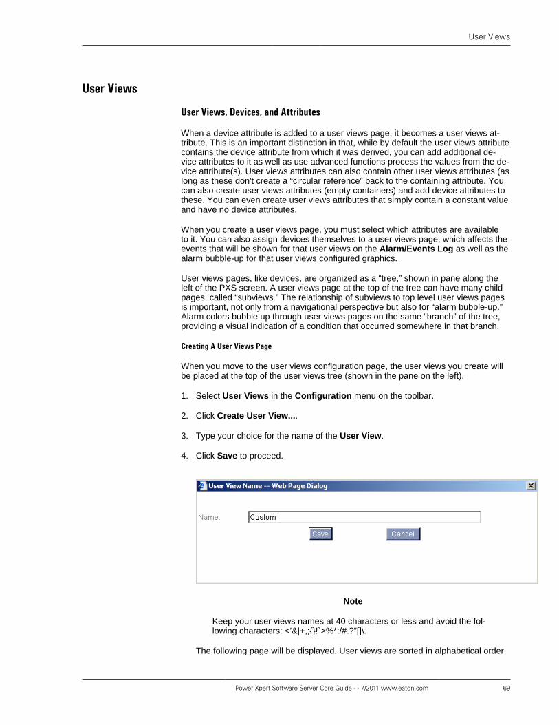
User Views
Power Xpert Software Server Core Guide - - 7/2011 www.eaton.com 69
User�Views
User�Views,�Devices,�and�Attributes
When a device attribute is added to a user views page, it becomes a user views at-tribute. This is an important distinction in that, while by default the user views attributecontains the device attribute from which it was derived, you can add additional de-vice attributes to it as well as use advanced functions process the values from the de-vice attribute(s). User views attributes can also contain other user views attributes (aslong as these don't create a “circular reference” back to the containing attribute. Youcan also create user views attributes (empty containers) and add device attributes tothese. You can even create user views attributes that simply contain a constant valueand have no device attributes.
When you create a user views page, you must select which attributes are availableto it. You can also assign devices themselves to a user views page, which affects theevents that will be shown for that user views on the Alarm/Events Log as well as thealarm bubble-up for that user views configured graphics.
User views pages, like devices, are organized as a “tree,” shown in pane along theleft of the PXS screen. A user views page at the top of the tree can have many childpages, called “subviews.” The relationship of subviews to top level user views pagesis important, not only from a navigational perspective but also for “alarm bubble-up.”Alarm colors bubble up through user views pages on the same “branch” of the tree,providing a visual indication of a condition that occurred somewhere in that branch.
Creating�A�User�Views�Page
When you move to the user views configuration page, the user views you create willbe placed at the top of the user views tree (shown in the pane on the left).
1. Select User Views in the Configuration menu on the toolbar.
2. Click Create User View....
3. Type your choice for the name of the User View.
4. Click Save to proceed.
Note
Keep your user views names at 40 characters or less and avoid the fol-lowing characters: <’&|+,;{}!`>%*:/#.?”[]\.
The following page will be displayed. User views are sorted in alphabetical order.

User Views, Devices, and Attributes
70 Power Xpert Software Server Core Guide - - 7/2011 www.eaton.com
Adding�Devices�and�Device�Attributes�to�a�User�View�Page
You can add both devices and individual device attributes to a user views page.Adding a device does not add its attributes; rather, it’s used in alarm bubble up andin determining what’s displayed on the Alarms/Events Log. Only those devicesthat are explicitly added to a user views page (or its subviews) will be considered foralarm/event bubble up color changes. If you add a server, all of its devices will beadded to the user view page. You do not need to add a device to a user view page toadd attributes from that device.
To add a device to a user views page:
1. Click the device in the Available Devices list.
2. Click the left arrow button. The device will appear in the Devices list.
Adding attributes makes the data feed from that attribute available to that user viewspage. These attributes are all shown in list view and are available to page designersusing the Layout Manager to create graphical user views. They are also available tothe Trend Viewer.
To add attributes from any device attached to PXS:
1. Click Add Attribute(s)...
2. Click a device or user views in the tree to select it. PXS will populate the Avail-able Attributes list with the various attribute categories available for that device.

User Views, Devices, and Attributes
Power Xpert Software Server Core Guide - - 7/2011 www.eaton.com 71
3. Click the expand button (plus sign) to list attributes under each category of inter-est.
You can multiselect attributes using Ctrl-click. Click directly on each attribute cat-egory to select all of the attributes in that category. Continue Ctrl-clicking attributecategories to add all of their attributes to the set of selected attributes (see the fol-lowing figure).
4. When you’ve selected the attributes that you wish to add, click the Add to UserView button.
Repeat the above procedure to add attributes from each device or user view of inter-est.
Adding�a�Subview
A subview can be used for attributes that you do not wish to show at the top level(where you might display only your most critical attributes) or it may be used for at-tributes of a subordinate device. This becomes very useful with hierarchical, graphicalstructures when using Layout Manager. To add a subview, simply click Add Subviewand follow the same procedure as described above for creating a standard user view.
User�Views�Editing�Icons
You can use the icons beside the user views to add a subview, rename a user view,or delete a user view.

User Views Attributes
72 Power Xpert Software Server Core Guide - - 7/2011 www.eaton.com
User�Views�Attributes
Device attributes are simply data feeds from the various devices in your network.Each device attribute represents a single type of information, such as a measuredvalue, the status of an input or output, or information about that device (e.g., its modelname). However, once added to a user views page, attributes become more flexible.You can use user views attributes to:
• Change the units for the displayed value (for example KW instead of W).
• Combine several attributes and then process their values to create a new attributevalue.
• Create a constant value for testing purposes when using the layout editor (for ex-ample, testing alarm colors).
• Write a script in the Python language to do sophisticated, complex processing onone or more data feeds.
If you wish to do more than simple arithmetic processing on a single value, you’ll nor-mally create a new, empty attribute. After you’ve created an empty attribute, you canreference the data feeds from one or more other attributes to build up a formula orscript. You can add attributes from any device or user views page.
Clearly, you don't need the power of a Python script for most of the processing you'lldo. To make it as easy as possible to process data, PXS provides three formulatypes from which to choose:
Predefined formula This is the simplest type of formula attribute, and providesthe most commonly used functions for processing a set ofattributes with numeric values that share compatible units.For example, you can't mix values that have units of volt-ampere-hours and watts. You can select to calculate the:
• Average of a set of attribute values.
• Sum of a set of attribute values.
• The minimum of a set of attribute values.
• The maximum of a set of attribute values.
Simple formula These are similar to formulas in a spreadsheet applica-tion, and they support the following operators: +,-, /,*. Sim-ple formulas can also group expressions using parenthe-sis. Formulas are evaluated from left to right and follow therules of precedence from basic mathematics. Therefore,multiplication and division have precedence over additionand subtraction. If you can construct a formula using Mi-crosoft Excel, you can easily use these.
A Simple formula can reference values from one or moreattributes. All attributes, including those that your create,are by default Simple formulas.
Script formulas These are multi-line scripts using the IronPython imple-mentation of the Python scripting language. As such,they require both a knowledge of Python and a fairly in-timate knowledge of PXS. These scripts are most use-

User Views Attributes
Power Xpert Software Server Core Guide - - 7/2011 www.eaton.com 73
ful to users with a great deal of experience with PXS. Ifyou choose to create this type of attribute formula, PXSlaunches a built-in script editing window that has syntaxvalidation and script testing features. If you think that youneed Script formulas, keep in mind that Eaton's field en-gineering group has the expertise to create these to meetyour needs.
Like Simple formulas, a Script formula can referencevalues from one or more attributes. It can also determinethe “quality” of the data feed.
In the above figure, formula 1 is a simple formula combining six attributes, formula2 is a script formula, and formula 3 is a predefined formula using the averaging func-tion. Note how each is shown in the Formula column.
Figure 19. The Three Type of Formulas Attributes Shown in the Attributes List
To create an empty user views attribute:
1. Select User Views in the Configuration menu.
2. Click a user views in the tree to select it.
3. Click Create Empty Attribute. The User View Attribute Name dialog box ap-pears.
4. Type a name for the attribute in the Name field and then click Save.
You’re now ready to add attributes to the empty attribute so that it can reference theirvalues. Remember to use attributes with common units. Keep in mind that you don'tadd attributes from within the new attributes, but rather you use the same Add At-tributes page used to add attributes to user views pages.
To add attributes to a users views attribute:
1. Select User Views in the Configuration menu.
2. Click a user views in the tree to select it. The attribute to which you will add otherattributes (your target attribute) must be on that user views.
3. Click Add Attributes:
4. Click a device or user views page that already has been assigned the attributesyou wish to use.

User Views Attributes
74 Power Xpert Software Server Core Guide - - 7/2011 www.eaton.com
5. Expand the appropriate category and click the attribute you wish to add. You canuse Ctrl-click to multi-select attributes.
6. In the Add to Formula list, select the target attribute. You can use the searchfunction by typing the first letter of the Display Name of the attribute. The selec-tion will jump to the first attribute with a Display Name starting with that letter.You can then scroll to the target attribute.
7. Click the Add To Formula button.
8. Continue adding attributes using this procedure until your target attribute has allthe references you need to build your formula.
9. Click the close box (upper right) to close the Add Attribute(s) dialog box.
To delete an attribute:
• Click the delete icon at the right of the attribute.
By default user views attributes use Simple formulas. However, you can change anyattribute into any of the formula types by clicking the Edit button, which launches theEdit User View dialog box, and selecting the appropriate radio button. Within the dia-log box, you can also set the following:
Name: This is the name assigned to the attribute, and helps users understandwhat the information is and where it came from. By default, it's a composite of the us-er views page name (or device name) and the default attribute name. If you processthe raw information from a device attribute using one of the formulas, it's a good prac-tice to reflect this in the attribute Name.
Category: PXS automatically groups similar attributes into pre-defined categories,such as Energy or Discrete IO. However, you can change the category to which anattribute belongs. This is most useful when you create an attribute yourself, as it al-lows you to assign it to the most logical group.
Value Type: Attributes may be of the following value types:
Real A “floating point” numeric value.Integer A whole number value.Boolean A two state value, shown as True or False.String A text string.DateTime A date-and-time value, given as mm/dd/yyyy hh:mm:ss:ms AM/PM
Units: The units that you wish to be displayed. Attribute values are given in "baseunits" which could be, for example, W, V, etc. However, you may wish to display anattribute value provided in some factor of this base unit, such KW instead of W. Sim-ply specify that factor as the Units. If Units matches the base unit provided by the at-tribute, then the base units are used without conversion. This is independent of theAuto units conversion and Calculation units.
Auto units conversion. Use this check box when the formula references multipleattributes with different base units. If selected, PXS will evaluate each value indepen-dently at the attribute level.
For example, suppose a formula references attributes from two devices, both ofwhich are monitoring energy usage. Further suppose that both device attributes haveunits of W but you wish to display the result as KW. Without Auto units conversionthe formula would be:

User Views Attributes
Power Xpert Software Server Core Guide - - 7/2011 www.eaton.com 75
(A1+A2)/1000
Similarly, suppose you wish to build a formula that references one device providingan attribute of energy usage in W and another providing energy usage in KW. If youwould like the result in KW, the formula would be:
A1/1000 + A2
However, if Auto units conversion is active, as long as the units of either devicemay be converted to KW the formula is simply:
A1+A2
Calculation units. The units applied to constants in your formula. By default theseare the same units as in the user views attribute. For example, in the formula A+100the constant 100 uses the calculation units.
Working�with�Predefined�Formulas
Predefined formulas let you easily apply the most commonly used post-processingfunctions to a either a single attribute value or a set of attribute values that all sharecompatible units. You can select this option from the Edit User View Attribute dialogbox.
To create a Predefined formula:
1. Select Predefined formula.
2. Choose one of the following functions from the drop down list: Avg(*), Sum(*),Min(*), or Max (*).
3. Click Save.
Building�Simple�Formulas
When you add one or more attributes to another attribute, they are assigned a vari-able name in the formula and automatically added to the formula itself. Variablenames start with A1 and increment as A2, A3, etc.
If you add two or more attributes, they appear as a sum. For example, A1+A2+A3.
To edit the default simple formula:
1. Click the edit icon (in the Edit column).
2. Edit the appropriate fields. The field values are defined as follows:
Name. This is descriptive text about the attribute.
Units. Type in the units that this attribute displays. For example, if your formu-la attribute is deriving a value from attributes that have units in amperes, your for-mula attribute will be amperes as well. Units defaults to that of the first attributeadded to the formula.
Category. Pick the appropriate category for the attribute from the drop downlist.
Formula. The arithmetic expression that defines the value for the formula.

User Views Attributes
76 Power Xpert Software Server Core Guide - - 7/2011 www.eaton.com
3. Modify the default formula as required. Remember, you can use +, -, /, and * andyou can group expressions using parenthesis.
4. Click the Save button to save your formula attribute and make it available to theassigned user view.
There are a couple of things to keep in mind when building a formula attribute:
• If you remove an attribute from the formula by removing its variable name, whenyou save that attribute is removed from the Attributes in Formula list.
• Power Xpert software does some validity checking when you attempt to save theformula attribute. If it detects an invalid character or an error in the formula, it willalert you to this and won’t save the formula attribute.
• The asterisk (*) is used for multiplication.
• If the formula contains a non-numeric value, such as a date, it can contain nothingelse.
• The numeric value of a constant remains the same, even if you change units. Forexample, if the constant value is 50 and you change the units from amps to kilo-amps, the constant will now represent 50 kiloamps.
Working�with�Script�Formulas
Script formulas are constructed using the IronPython implementation of thePython language. IronPython runs under both .NET and Silverlight. It's open sourceand you can read more about it at http://www.codeplex.com/wikipage?ProjectName=IronPython. For the purposes of Script formulas, you don't needto understand how to use either .NET or Silverlight. Script formulas are fairly simple

User Views Attributes
Power Xpert Software Server Core Guide - - 7/2011 www.eaton.com 77
Python programs and a basic knowledge of scripting in Python is all you should needto handle the programming tasks in a Script formula. What's more important is an un-derstanding of PXS and how to access attribute data from your scripts.
The following sections do not constitute a tutorial on using the Python language. Theyare a number of resources on the Internet you can access, as well as available booksand training classes for a basic introduction to Python. The following sections cover:
• The basic process of creating a Script formula.
• What IronPython functions aren't supported.
• How attribute data is passed to your script.
• What is meant by data quality.
• How to use the built-in formula editor. PXS has a Python editor which has a num-ber of convenience features to help you develop your scripts.
• Various examples of Script formulas highlighting specific capabilities.
The�Process�of�Creating�a�Script
For each script that you'll create, you'll follow these general steps:
1. Create a new, user views attribute. This is covered in To create an empty userviews attribute: [73]
2. Populate that user views attributes with the set of attributes that will provide thedata feeds you'll need. This is covered in To add attributes to a users views at-tribute: [73]
3. Create the script, using the script editor and the data from the attributes array.The attributes array is discussed in the section called “How Data is Passed FromAttributes” [78].
4. Validate your script using the Validate Syntax button at the bottom-left of theediting window. If syntax errors are found, the Validation result field shows theerror and the line on which it occurred.
5. Test the script using the Test Script button at the bottom-right of the editing win-dow. The Test Script button evaluates the script using the array values shown inthe Test Script With Data table. The value that the script returns is shown in theTest result field.
6. Click the OK button to close the editor.
7. Click the Save button.
Restrictions
IronPython is a powerful Python implementation that has a number of functions whichcould, if used maliciously, pose security risks to PXS, the server, and perhaps an en-tire network. To help prevent such security problems, the IronPython implementationin PXS has a number of restricted functions. Most of these functions deal with file I/Oor the ability to access external applications. The restrictions are:
• You can't use the word import in the script. This prevents the script from import-ing any library, external script file, or .NET assembly.

User Views Attributes
78 Power Xpert Software Server Core Guide - - 7/2011 www.eaton.com
• You can't use the following built-in functions: __import__, compile, dir, exec,execfile, eval, file, help, input, open, print, reload, or raw_input.
How�Data�is�Passed�From�Attributes
Data from each attribute that has been added to a user views attribute is added tothree separate arrays: v, q, and s. The v array contain the data feeds from the at-tributes, the q array provides the “quality” of the data feeds, and the s array containsstring representations of the various values from the data feeds. The quality arraycontains standard OLE for Process Control (OPC) quality values, with two propri-etary Eaton extensions. The string values in the s array are useful when working withboolean or multi-state data feeds where the value is something like true or false.
How to use the arrays is discussed in detail in the following section.
Introduction�to�the�Script�Editor
You can access the Script Formula Editor dialog box from the Edit User View At-tribute dialog box. Select Script formula and click the Edit/View Script button tolaunch the editor. You may be prompted to press the Space bar or Enter to activatethe editor.
Figure 20. Python Editor

User Views Attributes
Power Xpert Software Server Core Guide - - 7/2011 www.eaton.com 79
The editor is divided into the following sections:
Attribute arrays Listing of all of the referenced attributes as well as their array in-dices.
Quality handlingcontrols
These controls let you select how the script will handle OPC quali-ty. If Do not evaluate the script. is selected, then if the quality iseither “uncertain” or “bad”, the user views attribute will be consid-ered to have bad quality and the script will not be evaluated. How-ever, if Evaluate the script is selected, then the value and qualityof the user views attribute are determined by the script itself. If thescript returns an invalid value or none, it is considered to be badquality. There are two special functions that Eaton has defined foryou to help with this, and they are discussed in detail in the Scriptediting pane discussion.
Script editingpane
The editing pane provides a convenient editor for creating yourscripts. It includes the toolbar, with the following tools:
1. Undo and redo. These buttons let you undo a change or, ifyou change your mind, redo it.
2. Search. Type the string to search for into the field, and thenpress either the search forward or search backward button.
3. Font size. You can make the editor font larger or smaller. Youcan't change the typeface.
4. Cascading menus for useful Python functions, organized bycategory.
5. Menu of pre-defined, useful code snippets.
6. Clicking the Validate Syntax button checks the script forsyntactical errors. If the syntax check passes, you'll see Thecode is validated in the Validation result field. Other-wise, you'll see the line number containing the error as well asa description of the error.
7. This table provides a list of the values from the various at-tributes when you launched the Script Formula Editor. Notethat these are not real-time values, but rather random valuesyou can change to evaluate or test your script. However, theydo provide you with an idea of what the values are.
A value of 192 indicates in the q array indicates a good qualityvalue. This is actually the OPC Quality value in decimal. TheQuality value is an integer value from 0 to 65535. The variousBad Quality values all mean that the quality is considered badas a result of the evaluation of the formula itself. A value ofUncertain Quality/Sub Normal means that at least one of theattributes referenced by the formula currently has one of theBad Quality values. The set of possible quality values is:
Decimal Value Status
192 Good Quality
216 Good Quality/Local Override
255 No Quality/No Value
0 Bad Quality/Non Specific

Example Scripts
80 Power Xpert Software Server Core Guide - - 7/2011 www.eaton.com
Decimal Value Status
4 Bad Quality/Configuration Error
8 Bad Quality/Not Connected
12 Bad Quality/Device Failure
16 Bad Quality/Sensor Failure
20 Bad Quality/Last Known Value
24 Bad Quality/Communications Failure
28 Bad Quality/Out of Service
64 Uncertain Quality/Non Specific
68 Uncertain Quality/Last Usable Value
80 Uncertain Quality/Sensor Not Accurate
84 Uncertain Quality/EU Units Exceeded
88 Uncertain Quality/Sub Normal
0 Limit Field Quality/Not
1 Limit Field Quality/Low
2 Limit Field Quality/High
3 Limit Field Quality/Constant
?? Eaton Extension: Value Interpolated
?? Eaton Extension: Subscription Request Failed
For more information about OPC quality values, refer to theOPC specification (available from the OPC Foundation atwww.opcfoundation.org). How to use the quality value inyour scripting is covered in the section called “Using the are-Good Function to Determine Overall Quality” [81].
Example�Scripts
The following provides a number of example scripts, along with annotations. In all ofthe examples, a pound sign (#) at the beginning of a line is a comment indicator.
Returning�a�Constant�Value
The following example simply returns the constant value 3.333. Returning a con-stant value can be useful in testing alarms, etc. when creating a PXS layout.
#All formula Python code should return a value.#This simply returns a constant value.return 3.333
Using�an�Arithmetic�Expression
The following example averages the values from three device attributes that havebeen added. To do so, the values are references from the v array as v[0], v[1],and v[2]. The returned value is simply the average of the three device attribute val-ues.
return (v[0]+v[1]+v[2])/3
Note
The numeric value of a constant remains the same, even if you change units.For example, if the constant value is 50 and you change the units from ampsto kiloamps, the constant will now represent 50 kiloamps.
Using�a�Local�Variable
This example expands on the last by storing the result from the arithmetic expressionin a local variable and then applying further processing to the variable's value.

Example Scripts
Power Xpert Software Server Core Guide - - 7/2011 www.eaton.com 81
temp = (v[0]+v[1]+v[2])/3return temp * 2
Using�Conditional�Statements
This example combines both conditional statements and comparison statements aswell as using a variable.
if v[0]>v[1]: temp=v[0]else: temp=v[1]
if temp>v[2]: return tempelse: return v[2]
The first conditional statement compares the values from two device attributesand, if the 0 attribute in the array is greater than 1 attribute, it assigns the 0 at-tribute to the temp variable. Otherwise, it assigns the value from the 1 attributeto temp.The second if statement compares the value of the temp variable to the value of2 attribute in the array and, if temp is greater then it returns the value of temp.Otherwise, it returns the value from the 2 attribute.
Using�Math�Functions
Python has an extensive set of functions in the standard math library, and you canuse these to construct complex formulas.
return sin (v[0]+v[1]+v[2])
In this example, the sine of the sum of attributes 0 through 2 is returned.
Using�the�areGood�Function�to�Determine�Overall�Quality
The q array contains the quality values for the attributes that have been added to theuser views attribute. If you choose Evaluate the script, you can use two built-in func-tions Eaton has provided to help you determine if attribute values have good qual-ity or not. The areGood function checks the quality of all attributes that have beenadded to the user views attribute, and returns a value of None if the quality is notgood.
if not areGood(q):
return None; # return None to indicate bad quality for the user view attributeelse:
return (v[0]+v[1]+v[2])*2
The areGood function evaluates the quality of all of the attribute values in theuser views attribute array. If not areGood, one or more of the values is not ofgood quality.The value returned in the string None.If the attributes in the array all have values of good quality, then the function re-turns the sum of three of those values multiplied by two.
Using�the�isGood�Function�to�Determine�the�Quality�of�Individual�Attributes
While the areGood function evaluates the quality of all of the attributes in the array,the isGood function evaluates the quality of a single, specified attribute. The follow-ing example excludes any attribute with bad quality from a computation.

Example Scripts
82 Power Xpert Software Server Core Guide - - 7/2011 www.eaton.com
#use function isGood() and set value to 0 if quality is not good.
if not isGood(q[0]): v[0] = 0;if not isGood(q[1]): v[1] = 0;if not isGood(q[2]): v[2] = 0;
return (v[0]+v[1]+v[2]);
The isGood function sets the value for the 0 attribute to 0 if the attribute valueisn't good.The equation uses a zero value for any of the attributes if their quality is notgood.
Using�the�s�Array
As previously mentioned, the s array contains strings representing the state ofboolean or multi-state attributes. For example, the s array may have the strings Onand Off that correspond to either a closed or open state of a relay. The following ex-ample returns a value of 100 if the hypothetical relay is open and a value of 0 if it isclosed.
#Return 100 if s[0] is "Off", else return 0. if (s[0]=="Off"): return 100 else: return 0
The string representation of the value of the 0 attribute in the array is comparedto the string Off.
Using�Predefined�Constants
IronPython provides several predefined constants for your use, including pi and e.The following example shows the use of pi.
#use math constant pi and ereturn sin(pi/2) + log(e)
Defining�Your�Own�Functions
You can also define your own functions. The following function, max, returns the high-est of three attribute values.
#define a function max
def max(x, y): if (x > y): return x else: return y
#use the user-defined function
x = max(v[0], max(v[1], v[2]))return x
The function, max, is defined.The max function is applied to three attributes from the array.

Viewing�Trended�DataOf all the tools available for analyzing and resolving power issues, trending is one ofthe most powerful. Through the Power Xpert Trend Viewer you can examine trends inup to 20 trendable attributes quickly and easily.
The first step to use trending is to ensure that trend data is available to Power XpertSoftware. There are three ways that this data is made available to Power Xpert:
• Through a Power Xpert device
• Through PowerNet
• Through Foreseer
In this chapter, the first section describes how to use trending for a Power Xpert de-vice (a Power Xpert Meter in this example). There are two sections at the end of thechapter that explain how to configure trending for PowerNet (INCOM or Modbus de-vices) or Foreseer (UPSs). If you are working with an INCOM device or a UPS andyou know that trending has not been configured, proceed to these sections now.
Note
As of PXS 2.2 the trend viewer can now display trends that include minimum,maximum, and average values if these are provided by a device. After up-grading from PXS 2.1, if a device sends both trend values and average val-ues then PXS will begin using the average values for the main trend line.However, under the following set of conditions the trend values sent beforethe upgrade will be shown simply as data points in the plot:
• If the time range selected spans the upgrade time.
• If the time period is less than 12 hours.
Should this occur, you can customize the graph settings to use trend val-ues (not average values) for the main plot line, thus showing a trend line thatboth predates the upgrade as well as extends beyond it.
This will also occur if, at a later point, you upgrade device firmware and thenew firmware provides the additional trend data.
There are three ways to launch the Trend Viewer:
• From within a user views page.
• Via the Trend Viewer bar or menu selection, which launches the Trend Viewer at-tribute selection page.
• From within a List View Monitor Device page.
Accessing�the�Trend�Viewer�from�a�User�Views�Page
Launching the Trend Viewer from a user views page requires two objects on thepage: a check box (assigned to a trendable attribute) and a Trend Viewer object. TheTrend Viewer object, when clicked, launches the Trend Viewer window and preloadsit with all trendable attributes selected by checkboxes.

Accessing the Trend Viewer from the Trend ViewerBar or Menu
84 Power Xpert Software Server Core Guide - - 7/2011 www.eaton.com
Accessing�the�Trend�Viewer�from�the�Trend�Viewer�Bar�or�Menu
Click the Trend Viewer bar on the left side of the screen or use the pull-down Nav-igation menu on the toolbar. Note that the “bars” on the left will move to the bottomleft of the screen if you are viewing other areas of the user interface.
Selecting�Attributes�for�Trending
The left side of the selection page has a tree containing all the devices monitored byPower Xpert Software. These are listed directly under Networks, while INCOM de-vices are listed under PowerNet Server and UPSs are listed under Foreseer Serv-er. These products are underlying data acquisition and processing engines for PowerXpert Software.
On the left side of the screen, select the device or user views that you want to ana-lyze through trending. In this example, the Power Xpert Meter has been selected. Ifyou select a user views page, you can select any trendable attributes assigned to thatuser views page, even if they are from different devices.
Figure 21. Monitor Tree
By default, the bottom pane of the attribute selection page shows all trendable at-tributes for the selected device or user views page. You must select the attribute(s)that you wish to graph and create a Trending Group before you can view them.
The Show All Attributes radio button, when selected, expands the list to include allattributes. This is useful if you wish to select an attribute that you anticipate will havetrend data. For example, the attribute may not have started accumulating trend dataor may not yet be configured.

Selecting Attributes for Trending
Power Xpert Software Server Core Guide - - 7/2011 www.eaton.com 85
Figure 22. Trend Viewer Pane
To select attributes for trend analysis:
1. In the bottom pane, click each attribute you wish to view. You can use Shift-clickto select a the top and bottom of set of attributes or select multiple attributes withCtrl-click. Selected attributes will highlight.
Figure 23. Loading the Selected Attributes
2. Click the up arrow button to load the set of selected attributes into the top pane.
3. Type a name in the Trending Groups field.

Editing Attribute Lists
86 Power Xpert Software Server Core Guide - - 7/2011 www.eaton.com
4. Click the Save Group button (you can now reload the group later).
5. Click the Display Selected Trends button. This launches the Trend Viewer.
Editing�Attribute�ListsTo open an existing group:
1. Select a group in the Trending Groups list.
2. Click Open Group.
To delete an item from the list:
• Click the Delete icon to the right of the attribute.
To clear all entries and create a new group
• Click the Clear link above and to the right of the Attributes Selected pane.
To delete the current group (if previously saved):
• Click Delete Group.
To Save a Group:
• Click Save Group.
Attributes can be displayed together on a chart or separately. You can designate anyattribute to display on up to four separate charts.
To select trend charts for an attribute:
1. Click the Edit icon to the left of the attribute.
2. Select each chart that will contain that attribute.
Figure 24. Selecting the Chart
3. Click OK.
Once you’ve selected the attributes to display, given the group a name, and savedthe group, you’re ready to display the trend data.
To launch the trend viewer:
• Click the Display Selected Trend(s) button.
Accessing�the�Trend�Viewer�from�Monitor/List�ViewFrom the Monitor, you can graph any trendable attributes from any device in the Net-work tree or any user views page. The Monitor must be in List View (not GraphicsView) to do this.

Using the Trend Viewer
Power Xpert Software Server Core Guide - - 7/2011 www.eaton.com 87
To access the Trend Viewer from the Monitor:
1. Select either a device or user views page in the System tree.
2. Click the Go To List View link.
3. Select the trends to view (up to 20).
4. Click Display Selected Trends.
Figure 25. Selecting Attributes to Display
Using�the�Trend�ViewerThe trend viewer displays in a separate window with up to four separate charts. Eachchart has separate controls. A set of display options governs the look-and-feel of theTrend Viewer page itself.
Figure 26. Trend Viewer

Trend Viewer Controls
88 Power Xpert Software Server Core Guide - - 7/2011 www.eaton.com
Each chart displays the trend data as a color-coded plot line, with a keyed set of plotcontrols beneath the chart. The x-axis shows time and the y-axis shows magnitude.Note that the bottom chart has candlesticks, denoting the minimum, maximum, andaverage values reported for that time interval. If minimum, maximum, and averagedata is available, you can also display these as separate trend lines.
Trend�Viewer�Controls
The toolbar has the following controls:
Time Selector Selects range of data from two hoursto one year, or custom (you selectthe beginning and end time/date withcalendar controls).
Refresh Refreshes the current data set basedon the Time Selector setting.
Custom Same as custom in Time Selector
Move Time Range Backward Moves the time range backward bythe current Time Selector period.
Move Half Time Range Backward Moves the time range backward byhalf of the current Time Selector pe-riod.
Set Time Range to Current ZoomRange
Resets the current time period to theperiod defined by the Zoom In box.
Move Half Time Range Forward Moves the time range forward by halfof the current Time Selector period.You cannot move into the future.
Move Time Range Forward Moves the time range forward by halfof the current Time Selector period.You cannot move into the future.
Cursor Removes/displays the vertical linecursor on the x-axis.
Grid lines Removes/displays the x and y-axisgrid lines.
Markers Removes/displays the data pointmarkers along the display.
Zoom In Sets the zoom function. By default,when you click-and-drag a zoom boxon the graph it zooms in on both thex and y-axis. You can also select tozoom in only on the x or y-axis.
Zoom Out Zooms out to the current range spec-ified by the Time Selector.
The Chart and Data tabs switch between the graphical (plot) view and a table listingthe datapoints. The Minimize button (upper right) minimizes the current chart
To zoom in on a section of a chart:
1. Click and drag a bounding rectangle over the area that you wish to fill the chartwindow.
2. Release the mouse button. The chart will zoom to the area defined by the bound-ing rectangle.
To pan left or right:
• Slide the scroll bar.

Viewing and Exporting Data
Power Xpert Software Server Core Guide - - 7/2011 www.eaton.com 89
To set the time range to the current zoom level:
• Click the Set Time Range (down arrow) button.
To zoom back to the current Time Selector setting:
• Click the Zoom Out button.
The Chart toolbar (under each chart) has the following functions:
Plot Identifier Shows the plot color and name ofthe attribute.
Show main trend line Toggles the main plot line. If the at-tribute provides minimum, maximum,and average data, this is the averageplot.
Show candlesticks Toggles the candlestick bars for min-imum and maximum values.
Show minimum trend line Toggles the plot line for minimumvalues (if present in the attribute da-ta).
Show maximum trend line Toggles the plot line for maximumvalues (if present in the attribute da-ta).
Show trend line with separate y-axis Toggles an extra y-axis for that trendline, which overlays the trend plots.
Shrink checkbox panel Hides or shows the check box con-trols. Hiding these controls providesmore room.
Attribute detail Launches a information box contain-ing details about that attribute.
Edit Launches a dialog box throughwhich you can change the name dis-played for the attribute and the linecolor.
Setting�Options
You can use Options to set the time source, as well as the time-and-date format. Toaccess the Options dialog box, select Options from the Tools menu. You can setthe following:
Time source. You can select from Server Time, Browser Time, or UTC.
Date format. You can select from several US or international time formats.
Decimal points. The precision used in the graph display.
Trend Line thickness. The thickness of the lines, set in points.
Font size. This is similar to browser font size settings, with larger and smallerchoices.
Start up options. Sets the plot behavior for start up. If data is available, the graphcan be set to start up with the following options active: main trend line, candlesticks,minimum value trend line, and the maximum value trend line.
Viewing�and�Exporting�Data
Clicking the Data tab reveals all of the data points within the specified time range foreach attribute in the chart. Data is displayed in this tab even if the plot check box iscleared. If you wish to temporarily remove an attribute from the Data tab, clear the at-tribute check box at the bottom of the window.

Viewing and Exporting Data
90 Power Xpert Software Server Core Guide - - 7/2011 www.eaton.com
Figure 27. Data Tab
Using the Filter button, you can restrict the data shown in the Data tab by data qual-ity, number value, or by a minimum and maximum data value. Data Quality Typerefers to whether the data quality is good, bad (unavailable), or questionable. TheValue Type Filter allows you to restrict data to only that with a valid number or da-ta that is not in numeric format, called Not a Number (NaN). The Value range filter al-lows you to restrict the data set by setting an upper and lower value. Note that all ofthese apply to all attributes; you cannot filter on individual attribute columns.
Figure 28. Filter Data Dialog Box
Using the Export button, you can export the set of data to either a comma-separat-ed values (CSV) file or an XML file. The CSV file can be opened by Microsoft Excelor other spreadsheet or database applications. The XML file is largely for exportingdata to other systems. The XML format is very simple and straightforward, with ele-ment types to mark the attribute name and beginning of attribute data, and elementfor each data point. The data element has the various values (shown as fields in thedata tab) as attributes of the element.

Trending an Attribute Formula
Power Xpert Software Server Core Guide - - 7/2011 www.eaton.com 91
Figure 29. Exported Data
Trending�an�Attribute�Formula
Trending an attribute containing a formula is performed in much the same way astrending any other attribute. The only caveat is that all attributes reference in theformula must be trendable. If, for example, you would like to trend the sum of threetrendable currents (A1, A2, and A3), you must first assign these three attributes toan attribute and then create a formula to sum them (see the section called “Restric-tions” [77]).
Trending�an�Integer�Attribute
Integer attributes provide data in integers only, and include binary attributes. Whenplotted, these attributes create trend lines that appear to be step functions. Binary at-tributes appear as a square wave.
Tips�for�Getting�the�Best�Trend�Plots
Consider the following when building trend graphs:
• If the minimum values and maximum values are very close to the average, the can-dlestick graph won't provide much in the way of useful information.
• Turn off the candlestick display before using overlaying trend plots using the Y-Ax-is control. Overlaid candlestick plots are extremely difficult to read.
• If a minimum, maximum, or average value isn't available for a given attribute, theTrend Viewer will still display the values that are available.
• All attributes that have aggregated trend data include minimum, maximum, and av-erage data; however, not all raw data includes these.
Trending�in�PowerNet
This section provides basic steps to configure trending in PowerNet. In some cases,there are other menu items and advanced features. They will not be covered here.For more information refer to PowerNet User’s Guide and Help.
To configure trending in PowerNet, first launch the PowerNet Configurator. The mainscreen of PowerNet Configurator is displayed along with the Select Edit Mode dialogbox. By default, On-line mode is selected. Since this is the desired mode, click OK.

Trending in PowerNet
92 Power Xpert Software Server Core Guide - - 7/2011 www.eaton.com
The Device Server Select dialog box is displayed. Select the device server to whichthe device of interest (FP-5000) belongs. Click OK.

Trending in PowerNet
Power Xpert Software Server Core Guide - - 7/2011 www.eaton.com 93
The Network Tree is displayed. With the device of interest (FP-5000) highlighted,click the Edit menu located in the lower right of the screen.

Trending in PowerNet
94 Power Xpert Software Server Core Guide - - 7/2011 www.eaton.com
Using the pull-down menu, select Trend.

Trending in PowerNet
Power Xpert Software Server Core Guide - - 7/2011 www.eaton.com 95
The Edit Trends dialog box is displayed. Highlight the attribute of interest and usethe arrow to bring it to the Trend Attribute column. Multiple attributes may be select-ed (use the Ctrl key) at one time. The Frequency with which datapoints are gatheredmay be set using the pull-down menus on the left side of the dialog box. Click OK.

Trending in Foreseer
96 Power Xpert Software Server Core Guide - - 7/2011 www.eaton.com
Trending is now set-up for these attributes.
Trending�in�Foreseer
This section provides the basic steps to set-up trending in the Foreseer. In some cas-es there are other menu items and advanced features. They will not be covered here.For more information, refer to the Foreseer documentation and help.
To begin, launch the Foreseer server from the Eaton Power Xpert group in the Startmenu. A tree view of the system will be displayed. Click a device, right-click a data-point in the Channel column and select Properties.
The Properties dialog will appear.

Trending in Foreseer
Power Xpert Software Server Core Guide - - 7/2011 www.eaton.com 97
By default Foreseer will poll data every second (60 datapoints per minute). The trend-ing function uses one value per minute. Note that Foreseer provides a choice of val-ues to be used.
In the dialog box, select the Archive pull-down menu to select use of the average,minimum, maximum, first or last value (from the 60 datapoints) as the value to repre-sent that particular minute. The value is then placed in the trending database for useby Power Xpert. Click OK.
Now, right-click again on the same channel and select Properties. This time, selectthe Advanced tab. Check the Publish BACnetWS+ trend data box. Click OK. Thismakes the data gathered by the Foreseer available to Power Xpert.

98

Configuring�Alarm�NotificationsPower Xpert Software has the ability to notify users when an alarm or event occursthrough the use of six main services:
1. Alpha Page Service
This method of notification uses a modem and a pager service. It is similar to textmessaging. Alphanumeric messages can be sent.
2. Numeric Page Service
This method also uses a modem and pager service. However, only pages con-taining numbers can be sent (For example, “911” can be sent for a high priorityalarm).
3. Printer Service
An attached, configured printer will receive all notifications and print using prop-erties configured in this service. Dot matrix and impact style printers are also sup-ported.
4. Output to COM Port Service
All alarm notifications will be sent directly to an attached, configured COM Portdevice.
5. SMTP Mail Service
This is an email notification service, and it is the main method of notification. Alldirections will be specific to this service. This service is only available with anSMTP mail server. To use a POP or IMAP mail server, use the Command Lineservice. Note that emails will only be pre-populated if you are using a supportedmail application, such as Microsoft Outlook.
6. Command Line Service
Notifications can be configured to run commands in the Command Line Prompt.Examples include writing output to a POP or IMAP mail server or writing output toa Notepad document.
There are several tasks you must complete to configure the Message Manager:
1. Configure Notification Services: These are the various services that the MessageManager can use to notify users of alarms. You must set these up before you cancreate Notification Lists.
2. Specify Subscribers: This is the list of persons who will receive notifications fromthe Message Manager. Notification Lists require both a method for notification(Services) and targets for message (Subcribers).
3. Configure Notification Lists: These are lists of subscribers, and you can createmultiple lists and designate a default list.
4. Connecting to PXS servers: You must specify the PXS server to connect to. Oncea connection is established, when you save changes to the Message Managerconfiguration these are reflected in the PXS server.

Launching the Message Manager Configuration Ap-plication
100 Power Xpert Software Server Core Guide - - 7/2011 www.eaton.com
Also, if you’re using an Alpha or Numeric pager, you may need to set up a modem.This is covered in the section called “Setting up Modems” [106]. At the end of thischapter you’ll find information about backing up your configuration settings.
The Services tab defines the various notification services used by Message Manage-ment. Services include alpha/numeric paging, Windows Messaging, SMTP protocolto a mail server, printer, output to one of the computer’s COM ports, or an additionalmeans of communications controlled through the Windows command prompt.
The following sections detail setup for each service.
Launching�the�Message�Manager�Configuration�Application
You can either launch the Message Manager configuration application from eitherWindows Start → Eaton Power Xpert Software → Message Manager Configurationor through Message Manager in the Windows Control Panel.
SMTP
SMTP is probably the service that you’ll use the most, as it is a common method forconnecting to a mail server. To configure it:
1. In the Message Manager configuration application, select the Services tab, thenselect New.
2. Select SMTP Mail Service from the list.

SMTP
Power Xpert Software Server Core Guide - - 7/2011 www.eaton.com 101
3. A dialog box will open.
4. Click OK
a. For Service Name, enter any unique identifiable name.

Alpha Page Service
102 Power Xpert Software Server Core Guide - - 7/2011 www.eaton.com
b. For Message Subject, create a name that identifies that alarm.
c. The SMTP address is the location/address of your email server.
d. Type the From EMail Address.
e. If the authentication is required, select the check box and enter the usernameand password.
Alpha�Page�Service
Refer to the documentation provided by your Alpha Page provider to configure thistype of device.
Note
If using a Windows Modem for Alpha Paging functions, it must be configuredto 2400 Baud Rate, 7 Data Bits, Even Parity and 1 Stop Bit or communica-tions cannot be established.
Numeric�Page�Service
Refer to the documentation provided by your Numeric Page provider to configure thistype of device. Clicking on the Advanced tab to access those Numeric Paging Prop-erties.
Printer�Service
Message Manager can print to one or a set of printers. Use the Printer Service Prop-erties to specify when and how messages are printed.
COM�Service
You can direct messages directly to a device attached to a specific COM serial port.Refer to the documentation that accompanied your device to find the serial port setupparameter.
Command�Line�Service
In most instances where this service is used, it is to direct messages to a mail servervia a protocol other than SMTP, such POP3 or IMAP. PXS does not provide a facilityfor passing data to the command line; therefore, you may need to use multiple Com-mand Line Services to handle different messages.
SNMP�Service
Simple Network Management Protocol (SNMP) provides a framework for communi-cation between various network devices using the TCP/IP protocol. SNMP employsa Manager/Agent model. The Network Management System (NMS) monitors andcontrols one or more Agents. The Agent, in this case the Message Manager, has theability to asynchronously send alerts, or traps, to specified SNMP Managers to reportpredefined events.
The SNMP agent allows such messages to be sent from the Message Manager to anNMS to furnish enterprise-wide notification of critical events. By adding the SNMP op-tion, the NMS can monitor critical events occurring within all of the foundation equip-ment supported by Foreseer.

Setting up Subscribers
Power Xpert Software Server Core Guide - - 7/2011 www.eaton.com 103
There are 25 predefined Cautionary and 25 predefined Critical traps available. Theymay be used to identify unique channels, or they may group channels by category. Itis possible to use a single Trap Number multiple times.
1. SNMP Service Installation
The Microsoft SNMP service must be installed on the machine that also hosts theMessage Manager. Trap destinations and community strings are configured using theSNMP service properties.
In Windows Server 2008, the SNMP service is installed through the Add Featureswizard. In Windows Server 2003, it is loaded as part of the Management and Monitor-ing Tools. To load the Management and Monitoring Tools, use Control Panel > Addor Remove Programs > Add Windows Components.
To configure the SNMP service in Windows Server 2003, refer to: http://support.microsoft.com/kb/324263
To configure the SNMP service in Windows Server 2008, refer to:http://social.technet.microsoft.com/Forums/en-US/windowsserver2008r2networking/thread/ce5ec0fe-30a8-4b6e-a6ae-a4d1b8c9d047/
In Windows 7 or Windows XP, the SNMP service is a Windows component. Load itthrough Start > Settings > Control Panel > Add/Remove Programs, then select Add/Remove Windows Components. Select the Management and Monitoring Tools checkbox. You may be asked to insert your Windows media to install the service.
After installing the Windows SNMP service, you must next add the SNMP devicesto it. All SNMP managers must be added through the Windows SNMP service. Afterconfiguring the Windows SNMP service, you must next enable the SNMP service inthe Foreseer Message Manager.
To enable the SNMP service in PXS:
1. Click the Services tab.
2. Click New.
3. Choose SNMP Service from the pop-up menu.
4. In the SNMP Service Properties dialog box, click OK. The SNMP Service willappear in the list of services.
5. Click Save Changes.
Setting�up�Subscribers
1. Select the Subscribers tab, then select New to add a subscriber.

Setting up Subscribers
104 Power Xpert Software Server Core Guide - - 7/2011 www.eaton.com
2. Specify a Name for the subscriber (you’ll use this name when adding subscribersto the subscription list).
3. If the subscriber is currently not available (such as during trips or vacation), selectUnavailable.
4. Click New. The Available Time Properties dialog box will open. Provide thesubscriber’s availability information.

Setting up Notification Lists
Power Xpert Software Server Core Guide - - 7/2011 www.eaton.com 105
5. Select a service.
6. Type in the subscriber’s email address if the email service was selected.
7. Click OK.
Setting�up�Notification�Lists
1. Select the Notification Lists tab, then select New.
2. Provide a name for the Notification List and select Add.
3. Select all of the Subscribers who are to be included in the list and, with the de-sired personnel highlighted, press OK to return to the Notification List Proper-ties dialog box. A person’s place in the contact queue can be changed by high-lighting their Subscriber Name and then moving them Up or Down one positionat a time. You can delete individual entries simply by highlighting them and click-ing Remove. Click Properties to specify a delay for an individual entry.
4. Click the Advanced tab.
a. Enter the desired Frequency of Calls to specify the number of times the No-tification List will be called as well as how many times each individual on thelist will be called until a response is received.
b. Specify the Delay to determine how long after an alarm is reported beforemessaging is initiated on the Notification List. Also designate whether thisDelay is observed the first time the list is called.
c. Enable the desired Call Properties to indicate whether to call the entire Noti-fication List regardless of whether a response is received, allow higher prior-ity lists to take call precedence, and if listed personnel using the same serviceshould be notified with the same call.
d. Click OK.
To verify the configuration from the Notification List tab:
1. Click the Test Call button to open the Test Call dialog box.
2. Enter a sample message and click OK.

Connecting to a Remote Foreseer Server
106 Power Xpert Software Server Core Guide - - 7/2011 www.eaton.com
3. The status of the message will be displayed in the list at the bottom of the page.
4. Double-click the Message Caller Source to view the status messages.
Connecting�to�a�Remote�Foreseer�Server
The Message Manager is set, by default, to communicate with a PXS server runningon the local machine. However, you may wish to run the Message Manager on a sep-arate machine and connect via the network to the PXS server.
To connect the Message Manager service to a remote PXS system:
1. Click the Properties button in the lower pane of the dialog box.
2. If you don’t have the PXS server installed on the local machine, select the follow-ing line in the list of servers...
https://127.0.0.1:443
...and then click Remove.
3. Click Add to add the address of a remote PXS server.
4. In the Connect to dialog box, you can specify the computer name or IP addressof the PXS server, as well as the protocol and port number. For added security,the default connection uses HTTPS and port 443 (which is typical for this type ofconnection). While port 443 is likely already open, a good practice is to check thisin your firewall settings.
Note
If you opt to use HTTP for communications with PXS, port 80 is the default. Ifyou must use another port, remember to set this in PXS as well.
If you wish to configure the message sent when the specified computer isoffline, click Customize Messages. The variable CONNECT_TO will be re-placed with the address of the specified machine and the CURRENT_TIMEvariable will be replaced with the time that communications was lost.
Setting�up�Modems
Connection to pager services is often via modem, so if you’ve selected to use a pagerservice you’ll need to configure a modem as well.
To configure a new Modem for use:
1. Click the Modems tab.
Note
Any modems already configured within Windows can be added by justclicking Add Windows Modems.
2. Click New and the Modem Properties dialog box is displayed.
3. Enter a unique Name to identify the new modem.
4. Review the default connection settings for the modem and change them if nec-essary. These settings must be correct or the Message Manager cannot forward

Saving Settings
Power Xpert Software Server Core Guide - - 7/2011 www.eaton.com 107
alarm information to your modem. If you’re using a Windows modem for AlphaPaging functions, it must be configured in the Control Panel to 2400 baud rate,7 data bits, Even parity and 1 stop bit or communications may not be established.Verify these settings with your pager server provider.
5. Verify the port setting and change it to the communications port to which the mo-dem is attached, if necessary.
6. Similarly verify the baud rate for the device, altering it as required. The baud rateis available from the device’s manual or the paging company. Also review the Da-ta Bit, Parity and Stop Bit settings to ensure that they are correct for the namedmodem. Most alpha paging companies require a Baud Rate of 2400 with 7 DataBits, Even Parity and 1 Stop Bit.
7. Enter any special Modem Initialization Strings. Typically this setting remainsblank. If the modem does not respond with an OK, refer to its operation manual todetermine a Modem Init string (with a maximum of 80 characters) that will workproperly.
8. Also enter any required Modem Dial String characters. This setting should onlybe specified if the Modem Dial String is not ATDT.
Saving�Settings
To save the configuration, always make sure that you click Save Changes. If you exitfrom the configuration application before doing so, your changes will be lost.
Backing�Up�and�Restoring�Message�Manager�Settings
After you’ve successfully configured the Message Manager, it’s a good practice tobackup the settings.
To save the settings:
1. Click Backup/Restore.
2. Either accept the default location for the backup file or click the browse button toselect a folder.
3. Click Backup. A message box will confirm that the settings file was successfullywritten.
4. Click Exit.
Configuring�Alarm�Notification
1. Navigate to the Power Xpert Software home page and select Alarm Notificationfrom the Configuration menu.
The Alarm Notification Configuration page will open (at the System node inthe tree, by default).

Configuring Alarm Notification
108 Power Xpert Software Server Core Guide - - 7/2011 www.eaton.com
2. Select a server/device to configure its alarm notification.
• Each node in the tree must be configured separately.
• Only nodes in the network tree and the System root (i.e., not the User Viewstree) can be associated with notification lists.
• If the System node is configured with a list, all nodes in the tree will send alarmnotifications.
3. Select a notification list.

Configuring Alarm Notification
Power Xpert Software Server Core Guide - - 7/2011 www.eaton.com 109
4. Unless configured differently, all nodes will use the default settings and mes-sages.
• The default settings will only notify subscribers when an alarm occurs. A notifi-cation will not be sent for an alarm being cleared, acknowledged, or closed.
• A notification will only be sent if the alarm has a Highest priority and a Criticalseverity.
5. If you wish to customize the messages and notification criteria, clear Use defaultsettings and messages.
The Notify on priority and Notify on severity options as well as the Alpha Mes-sage text box will become enabled. If either a Numeric Page Service or Com-mand Line Service was configured, the appropriate text box for those serviceswould be enabled.
6. Check the desired priority and severity settings.

Configuring Alarm Notification
110 Power Xpert Software Server Core Guide - - 7/2011 www.eaton.com
7. Enter the message that will be displayed in the email.

Configuring Alarm Notification
Power Xpert Software Server Core Guide - - 7/2011 www.eaton.com 111
• Symbols can be used to insert information from Power Xpert Software at thetime of the alarm or event. To add a symbol, choose one of the following fromthe drop down list:
• $AlarmDesc$ - returns the alarm description.
• $DeviceName$ - returns the name of the device issuing the alarm.
• $Priority$ - returns the alarm priority.
• $ServerName$ - returns the server issuing the alarm.
• $Severity$ - returns the alarm severity.
• $Time$ - returns the time in which the alarm occurred.
• Click the Add Symbol button for each symbol you select.
8. Select Submit Changes at the bottom of the page to save the changes made.

Configuring for Bubble Up
112 Power Xpert Software Server Core Guide - - 7/2011 www.eaton.com
Configuring�for�Bubble�Up
You can configure notification so that alarms bubble-up from sub-nodes to highernodes in the tree (including the System node). If you wish to do this, keep the follow-ing guidelines in mind:
• By default, only alarms with the Highest priority and Critical severity will send alarmnotifications to the higher nodes.
• If you want alarms with a priority other than Highest (i.e., High, Normal, Low, andLowest) and severity other than Critical (i.e., Cautionary) to send alarm notificationsto the higher nodes, you must configure each node in the bubble-up path (includingthe System node) to have the following settings:
• A notification list must be selected for the top node in the bubble-up path (thenode from which the notifications are sent). This can be the System node.
• Clear the Use default settings and messages check box and then select thedesired Priority and Severity settings and notification type (i.e., Alarmed, Closed,and Cleared) as well as the messages that will appear in the emails.

Looking�at�Alarms�&�EventsThis chapter provides background information about alarms and events as well asa discussion of how to use the Alarms/Events Log in PXS. The criteria for alarmsand events are set at each device in your network and, when the devices are proper-ly configured, are sent to PXS. There are two ways to monitor alarms and events inPXS:
• Through the main Power Xpert Web Application. The Alarms/Events Log providesa view of alarms and events that have already occurred. This is not a dynamic viewand you won’t automatically see alarms or events show up on the page as they oc-cur, but an alert icon will appear to signal that a new alarm has occurred or an ex-isting alarm changed. You can update the page to see alarms and events that haveoccurred since the log was displayed.
• Through New Event Monitor. This Windows Notification application provides dy-namic alerts when an Alarm or Event occurs.
Alarm�&�Event�Terminology
The following terms are used throughout the alarms and events documentation:
Term Description
Description A description of the alarm or event. This is available inthe Description Field on the Alarms/Events Log.
Device The particular device and/or server for which the alarmor event occurred.
Attribute The parameter of interest. Also referred to as a datapoint and may be blank for Device or Internal alarms.
Time Logged The time the event occurred or the time when an alarmfirst occurred.
Cleared The physical condition that triggered the alarm/event iscurrently not present.
Ack or Acknowledge The alarm has been Acknowledged by a user throughchecking the Acknowledge box on the Alarms/EventsLog page. The alarm may also be acknowledgedthrough PowerNet, Foreseer, or a Toolkit device.
Close Makes the alarm historical in nature and read-only. Assuch, it is finalized and can’t be changed in any way. Ifan alarm must be manually closed, you can do this bychecking the box on the Alarms/Events Log.
Priority The is the alarm state. Alarms are categorized fromHighest to Lowest.
Detail Provides detail information about a particular alarm orevent. This is available by clicking an alarm or event en-try in the Alarms/Events Log.
New�Event�Monitor
The New Event Monitor immediately alerts you to a new or changed alarm or event.You must launch the monitor from the Power Xpert Software Web Application. Ifyou are on the Power Xpert server machine, you can launch this via Start > All Pro-grams > Eaton Power Xpert Software > Web Application. If you are accessingPower Xpert remotely via the Internet Explorer browser, type in the IP address for thePower Xpert Web Server followed by \PowerXpertSoftware. From the Web Appli-cation, select New Event Monitor from the Navigation menu (you will need adminis-trative rights for the client machine, or at least permission to install applications).

Alarm Models
114 Power Xpert Software Server Core Guide - - 7/2011 www.eaton.com
Figure 30. Installing the New Event Monitor
After starting, the New Event Monitor icon will appear in the notification area. Shouldan alarm or event either occur or change, the New Event Monitor pops up a messageand adds a yellow caution symbol to the notification tray icon.
Figure 31. An alarm or alert message from the New Event Monitor
You can launch the Alarms/Events Log to view this alarm/event, along with any oth-er alarms/events that have previously occurred, by double-clicking the Windows noti-fication icon. You can also launch the Alarms/Events Log by right-clicking the notifi-cation icon and selecting View Events.
To configure the New Event Monitor, right-click the icon in the system tray and selectConfigure In the New Event Monitor Settings dialog box, you can choose to:
Report regular events in addition to alarms. This is the default setting and theNew Event Monitor will alert you to both alarms and events.
Play alert sounds until alarm notifications are removed. Should you select thisoption, you can set the amount of time, from 1 to 9,999 seconds, between sounds.
Figure 32. New Event Monitor Settings Dialog Box
The New Event Monitor does not automatically load during computer startup, and youmust start it manually from within the Power Xpert Software Web Application. To stopthe monitor, right-click the system tray icon and select Exit.
Alarm�ModelsThe Alarms/Events Log can, depending on the devices connected to Power XpertSoftware, show alarms and events from a variety of systems and devices which have

Power Xpert Non-Autoclosing Alarm Model
Power Xpert Software Server Core Guide - - 7/2011 www.eaton.com 115
different alarm models. The Alarms/Events Log consolidates these and presentsa unified view; however, it’s important to have some understanding of the variousmodels in use. The following provides background information about how alarms andevents are handled in PXS.
Power�Xpert�Non-Autoclosing�Alarm�Model
Power Xpert devices have non-autoclosing and autoclosing alarms, though the ma-jority are non-autoclosing (sometimes called “latched”). This is determined by thetype of device and the importance of latching the alarm.
The following diagram and scenario details how this model responds:
Figure 33. Power Xpert Software alarm model
1. The PowerXpert device attribute value rises above the alarm threshold. TheNew Event Monitor alerts you that an alarm/event has occurred. If you open theAlarms/Events Log in the Power Xpert Software web application, this will appear

Power Xpert Software Autoclosing Alarm Model
116 Power Xpert Software Server Core Guide - - 7/2011 www.eaton.com
as a Cautionary alarm (yellow) in the set of alarms/events. You acknowledge thealarm.
2. The attribute value passes below the alarm threshold. In most cases, the NewEvent Monitor won’t alert you that the state has changed. However, if the Alarms/Events Log is open, the alert icon will signal that something has changed. Thealarm will now be set to Cleared, but it is still active and Acknowledged. You don’tClose it, and therefore it remains active.
3. The attribute value now rises above the alarm (Cautionary) threshold again. TheNew Event Monitor signals you. If the Alarms/Events Log is open, the alert iconsignals that something has changed. You click the refresh link and the alarm isshown as Cautionary and Acknowledged.
4. The attribute value now rises above the High Alarm (Critical) threshold. The NewEvent Monitor alerts you. If the Alarms/Events Log is open, the alert icon signalsthat something has changed. After you click the refresh link, the alarm is shownas Critical (red) and, because the alarm has changed to a “higher” state, the low-er-level Acknowledge is removed. You Acknowledge this alarm. The value thenrapidly cycles through the High Alarm (Critical) and Alarm (Cautionary) thresholdseveral times. The alarm remains Critical and Acknowledged. The Event Monitorand Alert icon don’t provide alerts to these changes (because the alarm state re-mains as Critical).
5. The value stops cycling through the High Alarm threshold, but is still in Alarm.The New Event Monitor and Alert icon don’t signal this change because the alarmstate remains as Critical. After you click the refresh link, the alarm is shown asCritical and Acknowledged. It’s still Acknowledged because you last Acknowl-edged it at the High Alarm (Critical - Red) state.
6. The value now falls below the Alarm threshold. The New Event Monitor doesn’tsignal this change; however, the alert icon on the Alarms/Events page does. Afteryou click the refresh link, the alarm is shown as Cleared and Acknowledged. Younow Close the alarm.
Note
If you Close an Acknowledged Alarm that is still in an alarm state (notCleared), the alarm will close but a new Alarm for that attribute will be de-clared.
One of major differences between PowerNet and Power Xpert Softwarealarm models is the condition that causes an alarm to be Closed. In Power-Net, an alarm automatically closes if it is both Acknowledged and Cleared,and these can occur in any order. For Power Xpert and Powerware devices,a non-autoclosing alarm (which the majority are) doesn’t Close automatically,and must be manually Closed.
Thus, it’s possible for a Power Xpert or Powerware device alarm to be Ac-knowledged and Cleared, but still active. In this case, if the attribute valuerises to a higher Alarm level (e.g., from Cautionary to Critical) then the Ac-knowledge is removed. This requires the user to re-Acknowledge the higheralarm level. Also, once an alarm has reached a higher level, such as Critical,even if the attribute value falls below the Critical alarm threshold that alarmcontinues to be shown as Critical.
Power�Xpert�Software�Autoclosing�Alarm�Model
Once an autoclosing alarm is Cleared (the alarm condition no longer exists), thealarm will automatically Close. If an attribute level rises from one alarm level to anoth-

Foreseer Alarm Model
Power Xpert Software Server Core Guide - - 7/2011 www.eaton.com 117
er the Acknowledge is removed. In this scenario, if an Alarm (Cautionary) occurs andis Acknowledged, but then the value rises to the High Alarm (Critical) threshold, theAcknowledge is removed.
Foreseer�Alarm�Model
This is identical to the Power Xpert System model, with a few differences in nomen-clature:
Power Xpert Software Term Foreseer Term
Attribute Channel
Non-autoclosing Alarm Latched Alarm
Otherwise, the behavior between Power Xpert and Foreseer alarm models is thesame.
PowerNet�Alarm�Model�Representation�in�Power�Xpert�Software
In a device connected through a PowerNet system, an alarm is shown as “Closed” inPower Xpert Software if:
• The alarm is manually closed in PXS through the Alarms/Events Log page.
• PowerNet closes alarm.
Keep the following in mind concerning PowerNet Alarms:
• Acknowledging or closing PowerNet alarms in the alarms/events log does notchange the status of the alarms in PowerNet. PXS does not send updates to Pow-erNet.
• A PowerNet alarm in the Alarms/Events Log will close only if it is manually closedin PXS or if PowerNet sends a closed status to PXS.
• A PowerNet alarm in the Alarms/Events Log will be acknowledged only if it is man-ually acknowledged in PXS or if PowerNet sends the acknowledge status to PXS.
• PowerNet closes its alarms after they have been acknowledged and cleared on thePowerNet side
• If PXS acknowledged a PowerNet alarm and then the alarm cleared, PXS will notclose the alarm unless the alarm was acknowledged in PowerNet as well.
• Note that if you manually close an alarm in PXS and PowerNet acknowledgesor clears it, the closed alarm will be acknowledged and cleared but it will remainclosed.

PowerNet Alarm Model Representation in PowerXpert Software
118 Power Xpert Software Server Core Guide - - 7/2011 www.eaton.com
Figure 34. A progression of state changes for a PowerNet device
1. The alarm threshold is reached, and an alarm state is sent to Power Xpertsoftware. The New Event Monitor signals that an alarm/event has occurred orchanged. When you open the Alarms/Events page in the Power Xpert Softwareweb application, this appears as a Cautionary alarm (yellow) in the set of alarms/events.
2. The value from the attribute falls below the Cautionary alarm threshold and Pow-erNet sends a status of Cleared to Power Xpert Software. If you had previouslyAcknowledged the alarm, it becomes Closed. If you Acknowledge it now, it alsobecomes Closed.
3. The value from the attribute once again reaches the alarm threshold and Power-Net sends an alarm state to Power Xpert software. The New Event Monitor postsits alert. If the Alarms/Events page is open, the alert icon signals that somethinghas changed. After you click the refresh link, a new alarm appears in the Activetab and the previously closed alarm appears in the Log tab. You Acknowledge thealarm.

Overview of the Alarms/Events Log
Power Xpert Software Server Core Guide - - 7/2011 www.eaton.com 119
4. The value crosses the high alarm threshold and PowerNet sends a state changeof High Alarm. The New Event Monitor alerts you. If the Alarms/Events page isstill open, the alert icon signals that something has changed. After you click therefresh link, the alarm state changes to show a High Alarm (Critical - red) and theAcknowledge is removed. You Acknowledge the High Alarm.
5. The value falls below the high alarm threshold and PowerNet changes the alarmstate to Alarm. The New Event Monitor alerts you. If the Alarms/Events page isstill open, the alert icon signals that something has changed. After you click therefresh link, the alarm state changes to show an Alarm and the Acknowledge isremoved. You then Acknowledge the Alarm.
6. The value falls below the alarm threshold and PowerNet changes the state toCleared. The New Event Monitor signals. If the Alarms/Events page is still open,the alert icon signals that something has changed. Because you had Acknowl-edged the alarm and it’s now Cleared, the alarm changes to Closed.
Overview�of�the�Alarms/Events�Log
If you are on the Power Xpert server machine, you can launch this via Start > AllPrograms > Eaton Power Xpert Software > Web Application. If you are accessingPower Xpert remotely via the Internet Explorer browser, type in the IP address for thePower Xpert Web Server followed by \PowerXpertSoftware.
There are three ways to access the Alarms/Events Log:
• Click the Alarm/Events Log button on the left side of the screen. Note that the“buttons” on the left will move to the bottom left of the screen when you are viewingother features of the user interface.
• Use the pull-down Navigation menu and select Alarms/Events Log.
•
Click the alarms indicator near the upper right corner.
The following figure shows an example of the Active tab from an Alarms/EventsLog.
Figure 35. Active Tab or Alarms/Events Log
Note
The Alarms/Events Log page shows a “snapshot” of the alarms and eventspresent when you last refreshed the page.

Alarms/Events Log Controls
120 Power Xpert Software Server Core Guide - - 7/2011 www.eaton.com
You can focus your view of the alarms and events by selecting a node on the Systemtree. For example:
• If you select System, you’ll see all alarms and events in PXS.
• If you select a device under Networks, you’ll see all alarms and events associatedwith that device.
• If you select a folder under User Views, you’ll see all alarms and events associat-ed with devices or device attributes specifically assigned to that user views page.
No matter what you select in the tree, internal PXS alarms and events always show inthe log.
Figure 36. Selecting a Node in the Alarm/Events Log Tree
Alarms/Events�Log�Controls
The Active and Log tabs switch your view from currently active alarms to historicalview of alarms and events shown in the log. Each tab title shows the total number ofalarms and events they contain. Clicking any alarm or event launches a Detail pagethat provides in-depth information about that particular alarm or event. The Detailpage contains such information as the time the event or alarm occurred, the devicefrom which it originated (and the attribute), links to waveforms, as well as when it wasacknowledged, cleared, and closed. The Detail page has a “tree” structure, and eachbutton with a + can be clicked to reveal additional information. If advice or potentialcorrective action is available from the system, this will appear in the Hint field.
You can also print information from the Detail page or export information from theDetail page to Microsoft Excel.
Note
If an alarm is part of a series of alarms or events for an attribute, the Detailpage for the subsequent alarms may not include all the information you’llwant to review. Check the Detail pages for the other alarms in the series.

Alarms/Events Log Controls
Power Xpert Software Server Core Guide - - 7/2011 www.eaton.com 121
Figure 37. Detail Page
By default, the Alarms/Events Log is set to show no more than the last 200 alarms/events, with 40 events to a page. The list is also restricted to only those alarms/events that have occurred in the last 30 days.
You can restrict which alarms and events are shown on the Log tab, as well as thetime span for showing alarms and events, by setting filters (click Filters to disclosethe filter controls). The Log tab only shows those alarms and events that meet thecurrent filter criteria. This capability, along with the ability to select nodes in the tree,provides considerable capability for filtering the information displayed. For moreinformation about filters see the section called “Log Tab Alarm and Event Filter-ing” [125].
To navigate to additional pages, use the First, Previous, Next, and Last links. Ifyou have large numbers of pages to navigate, consider using the filters to reduce thenumber of alarms and events displayed.
You can change the sort order or any column by clicking it once to select the column,and then clicking again to change the order. The small blue arrow indicates the cur-rent direction of the sort order.
The alarms/event entries are color coded to help you visually distinguish the severi-ty of each alarm/event or whether it has been acknowledged or whether it is inactive.The color coding scheme is as follows:

Alarms/Events Log Controls
122 Power Xpert Software Server Core Guide - - 7/2011 www.eaton.com
Color Meaning
Red Severity: Critical
Yellow Severity: Cautionary
Blue Acknowledged
Gray Closed alarm or event (in PXS, this is a historical alarm or event).
If a new alarm or event occurs while the Alarms/Events Log page is displayed, you’llsee the alarm bell icon flashing on the right side of the page (as shown in the follow-ing figure). You can click the alarm bell or the Update Display link under Tasks to re-fresh the contents of the Alarms/Events Log.
If a chart button appears in the Waveform column (or is available in the Detail page),you can view a waveform related to this alarm or event. Click the button to load therelated waveform data into the waveform viewer.
The various fields in each alarm or event entry have the following functions:
New Shows an orange star if the alarm or event was new in the last up-date to the page.
Description Provides a descriptive phrase about the alarm or event.
Device Shows the device from which the alarm or event was issued. If it’s aPXS internal alarm you’ll see the device identified as System.
Attribute Shows the specific attribute, if available, that triggered the alarm orevent.
Time Logged Shows the time that the alarm or event occurred.
Priority Shows the state of the alarm, which may have one of the followingvalues: Highest, High, Normal, Low, and Lowest.
Waveform Indicates if related waveform data is available. Click the button toview the waveform.
Cleared Indicates whether or not the alarm has been cleared.
Notes Launches a page you can use to record notes and responses for aparticular alarm or event.

Alarms/Events Log Controls
Power Xpert Software Server Core Guide - - 7/2011 www.eaton.com 123
Figure 38. An example Notes page

Alarm/Event Tasks
124 Power Xpert Software Server Core Guide - - 7/2011 www.eaton.com
Figure 39. Email Launches your default email program with information preloaded into the emailconcerning the alarm or event.
Alarm/Event�Tasks
At the top of the Alarm/Events Log are the Alarm/Event Tasks controls. These con-sist of:
Print Formats the alarms and events information for easy printing.The information appears in an Internet Explorer page, andyou can print it from the browser.
Export Exports the contents of the current tab into a Microsoft Ex-cel file and loads this into Excel.
Update Display This refreshes the list shown in the tab to show events andalarms that have occurred since the list was displayed. Onthe Log tab, the filter criteria still applies.
Customize Display This sets the fields and number of alarms or events that aredisplayed on both tabs.
Close All Closes all open events or alarms on the currently displayedtab.
Acknowledge All Acknowledges all unacknowledged alarms or events on thecurrently displayed tab.
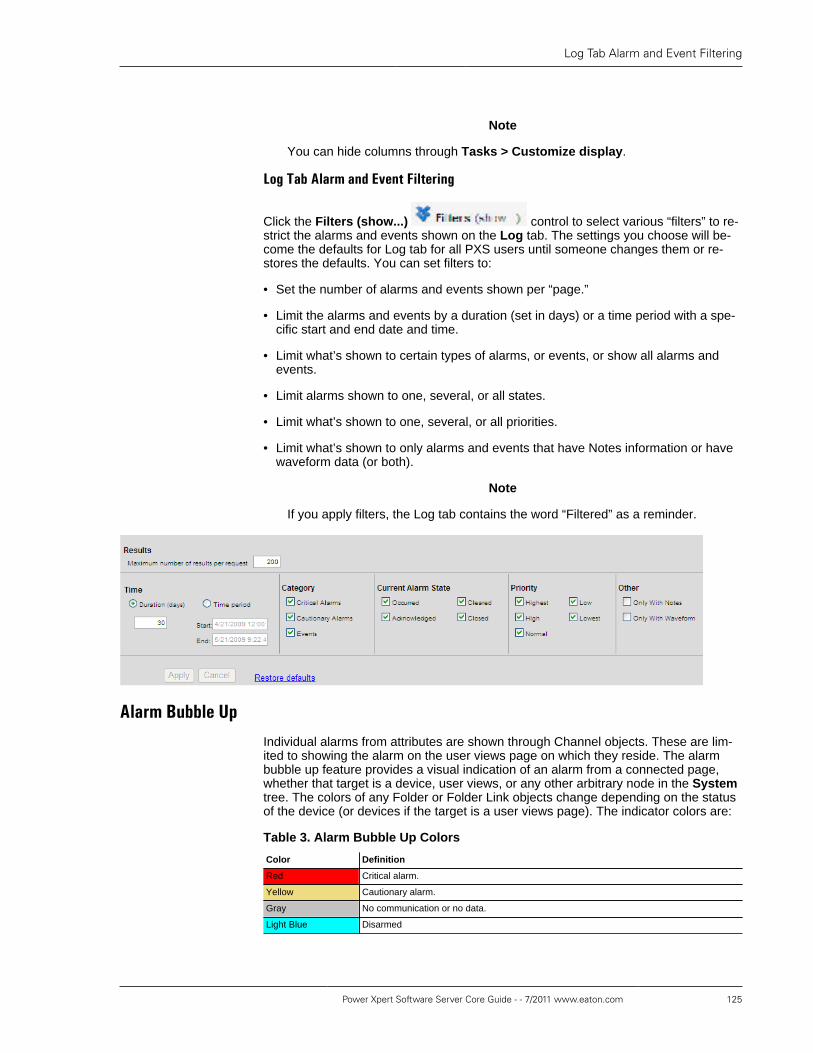
Log Tab Alarm and Event Filtering
Power Xpert Software Server Core Guide - - 7/2011 www.eaton.com 125
Note
You can hide columns through Tasks > Customize display.
Log�Tab�Alarm�and�Event�Filtering
Click the Filters (show...) control to select various “filters” to re-strict the alarms and events shown on the Log tab. The settings you choose will be-come the defaults for Log tab for all PXS users until someone changes them or re-stores the defaults. You can set filters to:
• Set the number of alarms and events shown per “page.”
• Limit the alarms and events by a duration (set in days) or a time period with a spe-cific start and end date and time.
• Limit what’s shown to certain types of alarms, or events, or show all alarms andevents.
• Limit alarms shown to one, several, or all states.
• Limit what’s shown to one, several, or all priorities.
• Limit what’s shown to only alarms and events that have Notes information or havewaveform data (or both).
Note
If you apply filters, the Log tab contains the word “Filtered” as a reminder.
Alarm�Bubble�UpIndividual alarms from attributes are shown through Channel objects. These are lim-ited to showing the alarm on the user views page on which they reside. The alarmbubble up feature provides a visual indication of an alarm from a connected page,whether that target is a device, user views, or any other arbitrary node in the Systemtree. The colors of any Folder or Folder Link objects change depending on the statusof the device (or devices if the target is a user views page). The indicator colors are:
Table 3. Alarm Bubble Up Colors
Color Definition
Red Critical alarm.
Yellow Cautionary alarm.
Gray No communication or no data.
Light Blue Disarmed

Low Disk Space Alarm
126 Power Xpert Software Server Core Guide - - 7/2011 www.eaton.com
Color Definition
Purple Disabled
Blue Acknowledged
Green Normal.
Multiple alarms can occur; however, only one color can bubble up. There are ordersof precedence that determine which color bubbles up. To see if multiple alarms exist,drill-down through the Folder Link to locate the source(s) of the alarm.
Formula attributes also change color depending on the state of the attributes thatthey reference.
For more information about bubble-up, see the PXS Layout Manager Guide.
Low�Disk�Space�Alarm
Should available disk space drop below 500 MB, PXS will issue a low disk spacealarm. PXS monitors both the drive on which it is installed and the drive on which thedatabase is installed. The low disk space alarm will be cleared when more disk spacebecomes available.

Restarting�Power�Xpert�from�a�Remote�ComputerYou can use the Power Xpert Software Configuration Manager to restart/start thePower Xpert Software service from Internet Explorer via a remote computer.
Configuring�Remote�Restart
Certain remote access and Windows Management Instrumentation (WMI) relatedservices must be enabled and running on the server machine for remote restart tofunction properly.
To configure the correct services on the Power Xpert server machine:
1. Right-click the My Computer icon and click Manage. The Computer Manage-ment window will appear.
2. In the tree (left side), expand Services and Applications and click Services.
3. Look in the list of Services (on the right) and verify that the following serviceshave the status of Started:
• COM+ Event System
• Remote Access Connection Manager
• Remote Procedure Call (RPC)
• Remote Registry
• Server
• Windows Management Instrumentation
• Workstation
4. If any of the services are not started, click the service name and then click theRestart link (upper left of the pane). It may take a few seconds to start the ser-vice.
Repeat this step with any other services on the list that currently aren’t started.
Configuring�the�Windows�Firewall
If you are using the Windows Firewall, use the following instructions to enable remoteadministration and modify Windows Firewall settings. If you are using a third partyfirewall, contact your network administrator to configure access.
To configure the Windows Firewall:
1. Log on to the Power Xpert server with an account that has local administrator au-thority.
2. From the Window Start menu, choose Run.
3. Type cmd and press Enter.
4. At the Windows command prompt, type the following command and then pressEnter.

Restarting/Starting the Power Xpert Service fromthe Configuration Manager
128 Power Xpert Software Server Core Guide - - 7/2011 www.eaton.com
netsh.exe firewall set service type=REMOTEADMIN mode=ENABLEscope=ALL
5. Type the following command and then press Enter (to verify that remote adminis-tration is enabled):
netsh.exe firewall show state
Look through the command output and verify that the Remote admin mode is en-abled.
Remote admin mode = Enable
6. Reboot the computer for these changes to take effect.
Restarting/Starting�the�Power�Xpert�Service�from�the�Configuration�Manager
This procedure describes how to restart the service from a remote computer.
To restart the Power Xpert service:
1. From the Windows Start menu, choose Eaton Power Xpert Software > Web Ap-plication:
2. In the Power Xpert Software window, choose Configuration Manager from theConfiguration menu.
3. Click the Restart icon.
4. Choose the Restart/start Power Xpert Software service in the remote machineoption.
5. Type the IP address of the machine you which to restart in the Remote machinefield.

Restarting/Starting the Power Xpert Service fromthe Configuration Manager
Power Xpert Software Server Core Guide - - 7/2011 www.eaton.com 129
6. Click the Change button in the Account box to change the account to that of theremote machine.
7. Change the Login to have the format of COMPUTERNAME\Administrator accountname and type the administrator’s password.
8. Click the OK button.
9. Click the OK button in the Restart/Start Power Xpert Service window.
10. Wait until the service is successfully restarted.

130

Database�ManagementDatabase�Management�Parameters
You can control the size of the Power Xpert Software database and the time spanfor which data is retained in the database through the Configuration Manager. Toaccess the Configuration Manager through the Windows Start menu, select AllPrograms>Eaton Power Xpert Software>Configuration Manager.
Click Database in the tree.
You can control the size of the database with the following:
Rolloff by Age: The number of months of historical data to keep. When purgingdata by age, an entire monthly database (a months worth of data) will be dropped.
Rolloff by Size: The maximum size historical data is allowed to reach beforerolloff occurs. During rolloff, individual records for Alarms, Events, and Trends will bepurged by oldest month until the total size of the database is below the size thresh-old.
You can choose to use both or either of the above rolloff policies (or not use the func-tion) through Rolloff Policy. Rolloff Frequency sets the time span between datarolloff operations. The default is set to one hour.
Note
Unless you have chosen to manually create monthly databases, do not turnoff automatic historical database generation. Manually creating monthlydatabases is covered in the Power Xpert Software Administration Guide.

132

Changing�the�Picture�and�Company�Name�in�theBanner
Power Xpert comes with a default picture in the banner (top of main screen) that youcan replace with your organization’s logo. You can also change the name that ap-pears when the mouse pointer hovers over the picture.
To change the company name:
1. Open Configuration Manager.
2. Select User Interface.
3. Edit the Company Name field and save.
Note
The company name will be overwritten during either an upgrade or a “repair”to PXS.
To change the photo:
1. On the PXS server machine, navigate to the C:>program files>Eaton Pow-er Xpert Software>webui>images folder.
2. Replace brand.jpg with the new image. The image must be 75 x 75 pixels to fitinto the allotted space.

134