Embed Size (px)
Citation preview

GETTING STARTED GUIDE
mmWave Transceiver System2 GHz Bandwidth mmWave Transceiver System
This document explains how to install and configure the National Instruments millimeter wave(mmWave) Transceiver System. The mmWave Transceiver System is a modular set ofhardware that can be used in various communications applications. This system ships with theNI-mmWave instrument driver, which you can use to program the system.
Caution Observe all instructions and cautions in the user documentation. Usingthe model in a manner not specified can damage the model and compromise thebuilt-in safety protection. Return damaged models to NI for repair.
Attention Suivez toutes les instructions et respectez toutes les mises en garde de ladocumentation utilisateur. L'utilisation d'un modèle de toute autre façon que cellespécifiée risque de l'endommager et de compromettre la protection de sécuritéintégrée. Renvoyez les modèles endommagés à NI pour réparation.
Caution If the device has been in use, it may exceed safe handling temperaturesand cause burns. Allow the device to cool before removing it from the chassis.
Attention Si l'appareil a été utilisé, il peut avoir atteint des températures tropélevées pour être manipulé en toute sécurité, ce qui peut provoquer des brûlures.Laisser l'appareil refroidir avant de le retirer du châssis.
Caution The system installation must adequately protect users' eyes from exposureto millimeter wave radiation output and input signals from the transmitter andreceiver.
Attention L'installation du système doit protéger correctement les yeux desutilisateurs contre l'exposition aux rayonnements d'ondes millimétriques des signauxen entrée et en sortie provenant de l'émetteur et du récepteur.
ContentsVerifying the System Requirements..........................................................................................2Unpacking the Kit..................................................................................................................... 2
System Configurations with mmWave Radio Heads........................................................ 4Installing the Software.............................................................................................................. 7Assembling mmWave Radio Head Tripods (mmRH-3647/3657)............................................ 7

System Setup...........................................................................................................................10Unidirectional System Setup...........................................................................................10Bidirectional System Setup.............................................................................................27Connecting mmWave Radio Heads to the System..........................................................38Configuring the Coding Modules of a MIMO System................................................... 50
Programming the mmWave Transceiver System.................................................................... 57NI-mmWave Instrument Driver...................................................................................... 57
Trigger Configuration............................................................................................................. 57Signal Block Diagrams........................................................................................................... 59
24.25 GHz to 33.40 GHz mmWave Transceiver System Block Diagram...................... 5937 GHz to 43.5 GHz mmWave Transceiver System Block Diagram............................. 5971 GHz to 76 GHz mmWave Transceiver System Block Diagram................................ 60
Front Panels, Back Panels, and Connectors............................................................................60Direct Connections to the mmWave Transceiver System............................................... 60PXIe-3610 Front Panel and LEDs.................................................................................. 61PXIe-3620 Front Panel....................................................................................................63PXIe-3630 Front Panel and LEDs.................................................................................. 65PXIe-7902 Front Panel....................................................................................................67mmRH-3602 Front/Back Panel and LEDs......................................................................68mmRH-3603 Front/Back Panel and LEDs......................................................................71mmRH-3642 Front/Back Panel and LEDs......................................................................74mmRH-3643 Front/Back Panel and LEDs......................................................................76mmRH-3647 Front/Back Panel and LEDs......................................................................78mmRH-3652 Front/Back Panel and LEDs......................................................................80mmRH-3653 Front/Back Panel and LEDs......................................................................82mmRH-3657 Front/Back Panel and LEDs......................................................................84
Where to Go Next................................................................................................................... 85
Verifying the System RequirementsTo use the NI-mmWave instrument driver, your system must meet certain requirements.
Refer to the product readme, which is available online at ni.com/manuals, for moreinformation about minimum system requirements, recommended system, and supportedapplication development environments (ADEs).
Unpacking the KitEach mmWave Transceiver System configuration includes chassis, modules, and cables.Additional chassis, devices, and cables may be included depending on added options.
2 | ni.com | mmWave Transceiver System Getting Started Guide

Table 1. Kit Contents by Configuration
Configuration Required MIMO Coding Option
Unidirectional singleinput, single output(SISO) (baseband)
• Receiver (RX) chassis• Transmitter (TX) chassis• Mini-SAS HD(m)-to-Mini-SAS
HD(m) (8.25 in.) cables (x9)
—
Unidirectional SISO(baseband andintermediate frequency(IF))
• RX chassis• TX chassis• Mini-SAS HD(m)-to-Mini-SAS
HD(m) (8.25 in.) cables (x9)• MMPX(m)-to-MMPX(m) cables
(x8)
—
Unidirectionalmultiple-input,multiple-output(MIMO) (baseband)
• RX chassis• TX chassis• Mini-SAS HD(m)-to-Mini-SAS
HD(m) (8.25 in.) cables (x19)
• Coding chassis• Mini-SAS HD(m)-
to-Mini-SASHD(m) (18 in.)cables (x2)
Unidirectional MIMO(baseband and IF)
• RX chassis• TX chassis• Mini-SAS HD(m)-to-Mini-SAS
HD(m) (8.25 in.) cables (x19)• MMPX(m)-to-MMPX(m) cables
(x16)
• Coding chassis• Mini-SAS HD(m)-
to-Mini-SASHD(m) (18 in.)cables (x2)
Bidirectional SISO(baseband)
• RX/TX chassis (x2)• Mini-SAS HD(m)-to-Mini-SAS
HD(m) (8.25 in.) cables (x18)
—
Bidirectional SISO(baseband and IF)
• RX/TX chassis (x2)• Mini-SAS HD(m)-to-Mini-SAS
HD(m) (8.25 in.) cables (x18)• MMPX(m)-to-MMPX(m) cables
(x16)
—
mmWave Transceiver System Getting Started Guide | © National Instruments | 3
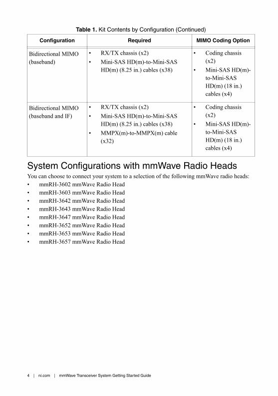
Table 1. Kit Contents by Configuration (Continued)
Configuration Required MIMO Coding Option
Bidirectional MIMO(baseband)
• RX/TX chassis (x2)• Mini-SAS HD(m)-to-Mini-SAS
HD(m) (8.25 in.) cables (x38)
• Coding chassis(x2)
• Mini-SAS HD(m)-to-Mini-SASHD(m) (18 in.)cables (x4)
Bidirectional MIMO(baseband and IF)
• RX/TX chassis (x2)• Mini-SAS HD(m)-to-Mini-SAS
HD(m) (8.25 in.) cables (x38)• MMPX(m)-to-MMPX(m) cable
(x32)
• Coding chassis(x2)
• Mini-SAS HD(m)-to-Mini-SASHD(m) (18 in.)cables (x4)
System Configurations with mmWave Radio HeadsYou can choose to connect your system to a selection of the following mmWave radio heads:• mmRH-3602 mmWave Radio Head• mmRH-3603 mmWave Radio Head• mmRH-3642 mmWave Radio Head• mmRH-3643 mmWave Radio Head• mmRH-3647 mmWave Radio Head• mmRH-3652 mmWave Radio Head• mmRH-3653 mmWave Radio Head• mmRH-3657 mmWave Radio Head
4 | ni.com | mmWave Transceiver System Getting Started Guide

Table 2. Unidirectional System Configurations with mmWave Radio Heads
Configuration mmRH-3642/3643/3652/3653 mmRH-3602/3603 mmRH-3647/3657
UnidirectionalSISO(baseband)
— — —
UnidirectionalSISO(baseband andIF)
• mmRH-3642/3643• mmRH-3652/3653• Single-channel EPLSP
cables (x2)• Digital I/O (DIO) adapters
(x2)• HDMI(m)-to-mini-
HDMI(m) cables (x2)• SMA(m)-to-SMA(m)
cables (x4)
— • mmRH-3647• mmRH-3657• mmWave radio
head tripods(x2)
• Single-channelEPLSP cables(x2)
• SMA(m)-to-SMA(m) cables(x4)
UnidirectionalMIMO(baseband)
— — —
UnidirectionalMIMO(baseband andIF)
• mmRH-3642/3643 (x2)• mmRH-3652/3653 (x2)• Single-channel EPLSP
cables (x4)• DIO adapter modules (x4)• HDMI(m)-to-mini-
HDMI(m) cables (x4)• SMA(m)-to-SMA(m)
cables (x8)
— • mmRH-3647(x2)
• mmRH-3657(x2)
• mmWave radiohead tripods(x4)
• Single-channelEPLSP cables(x4)
• SMA(m)-to-SMA(m) cables(x8)
mmWave Transceiver System Getting Started Guide | © National Instruments | 5

Table 3. Bidirectional System Configurations with mmWave Radio Heads
Configuration mmRH-3642/3643/3652/3653 mmRH-3602/3603 mmRH-3647/3657
BidirectionalSISO(baseband)
— — —
BidirectionalSISO(baseband andIF)
• mmRH-3642/3643 (x2)• mmRH-3652/3653 (x2)• Dual-channel EPLSP
cables (x2)• DIO adapter modules
(x4)• HDMI(m)-to-mini-
HDMI(m) cables (x4)• SMA(m)-to-SMA(m)
cables (x8)
• mmRH-3602/3603(x2)
• Single-channelEPLSP cables (x2)
• DIO adaptermodules (x2)
• HDMI(m)-to-mini-HDMI(m)cables (x2)
• SMA(m)-to-SMA(m) cables(x8)
• mmRH-3647(x2)
• mmRH-3657(x2)
• mmWaveradio headtripods (x4)
• Dual-channelEPLSPcables (x4)
• SMA(m)-to-SMA(m)cables (x8)
BidirectionalMIMO(baseband)
— — —
BidirectionalMIMO(baseband andIF)
• mmRH-3642/3643 (x4)• mmRH-3652/3653 (x4)• Dual-channel EPLSP
cables (x4)• DIO adapter modules
(x8)• HDMI(m)-to-mini-
HDMI(m) cables (x8)• SMA(m)-to-SMA(m)
cables (x16)
• mmRH-3602/3603(x4)
• Single-channelEPLSP cables (x4)
• DIO adaptermodules (x4)
• HDMI(m)-to-mini-HDMI(m)cables (x4)
• SMA(m)-to-SMA(m) cables(x16)
• mmRH-3647(x4)
• mmRH-3657(x4)
• mmWaveradio headtripods (x8)
• Dual-channelEPLSPcables (x8)
• SMA(m)-to-SMA(m)cables (x16)
6 | ni.com | mmWave Transceiver System Getting Started Guide

You can simultaneously connect different models of mmWave radio heads to the mmWaveTransceiver System. However, connecting models with different IF frequency ranges, such asthe mmRH-3642 and the mmRH-3647, may cause a non-ideal IF frequency to be used.
Related Information
Refer to the mmWave Transceiver System Specifications on ni.com for IF frequency ranges bymodel.
Installing the SoftwareYou must be an Administrator to install NI software on your computer.1. Install an ADE, such as LabVIEW.2. Install NI LabVIEW FPGA Module.3. (Recommended) Install the latest service pack for LabVIEW and any LabVIEW modules
you are using.4. Visit ni.com/info and enter the Info Code mmwavedriver to access the driver download
page for the latest NI-mmWave software.5. Download the NI-mmWave driver software.6. Run setup.exe.7. Follow the instructions in the installation prompts.
Note Windows users may see access and security messages duringinstallation. Accept the prompts to complete the installation.
8. When the installer completes, select Restart in the dialog box that prompts you to restart,shut down, or restart later.
Related Information
Programming the mmWave Transceiver System on page 57
Assembling mmWave Radio Head Tripods(mmRH-3647/3657)Complete the following steps to assemble the mmWave radio head tripods if yourconfiguration includes mmWave radio heads and tripod stability is desired.1. Install four 3/4 in. screws as shown in the following figure. Do not tighten.
mmWave Transceiver System Getting Started Guide | © National Instruments | 7

Figure 1. Assembling the Tripod
158972B–01
RE
V X
X
158972B–01
RE
V X
X
1
2
1. 3/4 in. Screws2. Stud Leveling Feet
2. Install three stud leveling feet as shown in the previous figure and use to adjust themmWave radio head to the desired mounting height. Jam nuts may be tightened to lockheight adjustment according to the specifications in the following table.
Table 4. Tightening Requirements for mmWave Radio Head Tripods
Item Max Torque (in. x lb) Driver Size
3/4 in. and 1/2 in. screws 11.5 7/64 in. hex
Stud leveling foot jam nut 11.5 3/8 in. hex
3. Install the mmWave radio head using six 1/2 in. screws as shown in the following figureand tighten them according to the specifications in Table 4.
8 | ni.com | mmWave Transceiver System Getting Started Guide

Figure 2. Assembling the Tripod with the mmWave Radio Head
4. Tighten the 3/4 in. screws according to the specifications in Table 4.
mmWave Transceiver System Getting Started Guide | © National Instruments | 9
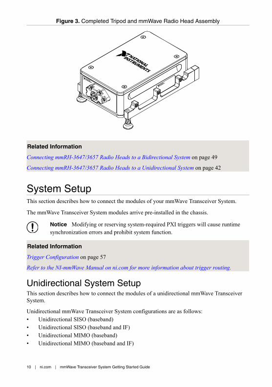
Figure 3. Completed Tripod and mmWave Radio Head Assembly
Related Information
Connecting mmRH-3647/3657 Radio Heads to a Bidirectional System on page 49
Connecting mmRH-3647/3657 Radio Heads to a Unidirectional System on page 42
System SetupThis section describes how to connect the modules of your mmWave Transceiver System.
The mmWave Transceiver System modules arrive pre-installed in the chassis.
Notice Modifying or reserving system-required PXI triggers will cause runtimesynchronization errors and prohibit system function.
Related Information
Trigger Configuration on page 57
Refer to the NI-mmWave Manual on ni.com for more information about trigger routing.
Unidirectional System SetupThis section describes how to connect the modules of a unidirectional mmWave TransceiverSystem.
Unidirectional mmWave Transceiver System configurations are as follows:• Unidirectional SISO (baseband)• Unidirectional SISO (baseband and IF)• Unidirectional MIMO (baseband)• Unidirectional MIMO (baseband and IF)
10 | ni.com | mmWave Transceiver System Getting Started Guide

Each configuration consists of two chassis, identical except for the unique components listedin the following table.
Table 5. Unique Components of Unidirectional System Chassis
Chassis Unique Component
RX PXIe-3630 Digitizer
TX PXIe-3610 Waveform Generator
Interconnecting the Unidirectional SISO (Baseband) ModulesComplete the following steps to connect the modules of the unidirectional SISO (baseband)mmWave Transceiver System configuration.1. Connect the adjoining PXIe-3630 and PXIe-7902 High-Speed Serial Instrument modules
in the RX chassis using four Mini-SAS HD(m)-to-Mini-SAS HD(m) (8.25 in.) cables.a) Connect the 0 connector of the PXIe-3630 front panel to the PORT 0 connector of
the PXIe-7902 front panel.b) Connect the 1 connector of the PXIe-3630 front panel to the PORT 1 connector of
the PXIe-7902 front panel.c) Connect the 2 connector of the PXIe-3630 front panel to the PORT 2 connector of
the PXIe-7902 front panel.d) Connect the 3 connector of the PXIe-3630 front panel to the PORT 3 connector of
the PXIe-7902 front panel.
mmWave Transceiver System Getting Started Guide | © National Instruments | 11

Figure 4. Interconnecting the PXIe-3630 and PXIe-7902 Modules
PXIe-3630I/Q Digitizer
REF IN
+10 dBmNOM
+13 dBmMAX
1.5 Vp-pDIFF MAX
1.5 Vp-pDIFF MAX
0 Vcm
ALL PORTS 50 Ω
REFOUT
0
1
2
3
Q+Q–
I+I–
ACCESS ACTIVE
PXIe-7902
CLKIN
PO
RT
2P
OR
T4
PO
RT
5P
OR
T3
PO
RT
0P
OR
T1
1
1. Mini-SAS HD(m)-to-Mini-SAS HD(m) (8.25 in.) Cables
2. Connect the PORT 4 connector of the PXIe-7902 front panel to the PORT 4 connector ofthe PXIe-7902 front panel using a Mini-SAS HD(m)-to-Mini-SAS HD(m) (8.25 in.)cable.
12 | ni.com | mmWave Transceiver System Getting Started Guide

Figure 5. Unidirectional SISO (Baseband) RX Chassis
PXIe-7902
CLKIN
PO
RT
2P
OR
T3
PO
RT
4P
OR
T5
PO
RT
0P
OR
T1
PXIe-7902
CLKIN
PO
RT
2P
OR
T3
PO
RT
4P
OR
T5
PO
RT
0P
OR
T1
PXIe-3630I/Q Digitizer
REF IN
+10 dBmNOM
+13 dBmMAX
1.5 Vp-pDIFF MAX
1.5 Vp-pDIFF MAX
0 Vcm
ALL PORTS 50 Ω
REFOUT
0
1
2
3
Q+Q–
I+I–
ACCESS ACTIVE
21 3 4 5 6 7 8 9 11 12 13 14 15 16 17 1810
NI PXIe-108510 MHz REF OUT IN24 GB/s
Embedded Controller
RESET
TRIG
ACT/LINK
ACT/LINK
2
1
10/100/1000
10/100/1000
USER1USER2
PWR OK/FAULTDRIVEGPIB
1
2
1. Mini-SAS HD(m)-to-Mini-SAS HD(m) (8.25 in.) Cables2. Mini-SAS HD(m)-to-Mini-SAS HD(m) (8.25 in.) Cable
3. Connect the adjoining PXIe-7902 and PXIe-3610 modules in the TX chassis using fourMini-SAS HD(m)-to-Mini-SAS HD(m) (8.25 in.) cables.a) Connect the PORT 0 connector of the PXIe-7902 front panel to the 0 connector of
the PXIe-3610 front panel.b) Connect the PORT 1 connector of the PXIe-7902 front panel to the 1 connector of
the PXIe-3610 front panel.c) Connect the PORT 2 connector of the PXIe-7902 front panel to the 2 connector of
the PXIe-3610 front panel.d) Connect the PORT 3 connector of the PXIe-7902 front panel to the 3 connector of
the PXIe-3610 front panel.
mmWave Transceiver System Getting Started Guide | © National Instruments | 13
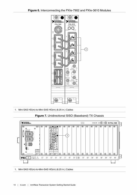
Figure 6. Interconnecting the PXIe-7902 and PXIe-3610 Modules
PXIe-3610I/Q Generator
PXIe-7902
0
1
2
3
REF IN
+10 dBmNOM
+13 dBmMAX
2 Vp-pDIFF MAX
2 Vp-pDIFF MAX
0 Vcm
ALL PORTS 50 Ω
REFOUT
Q+Q–
I+I–
PO
RT
4P
OR
T5
PO
RT
2P
OR
T3
PO
RT
0P
OR
T1
ACCESS ACTIVE
CLKIN
1
1. Mini-SAS HD(m)-to-Mini-SAS HD(m) (8.25 in.) Cables
Figure 7. Unidirectional SISO (Baseband) TX Chassis
21 3 4 5 6 7 8 9 11 12 13 14 15 16 17 1810
NI PXIe-108510 MHz REF OUT IN24 GB/s
Embedded Controller
RESET
TRIG
ACT/LINK
ACT/LINK
2
1
10/100/1000
10/100/1000
USER1USER2
PWR OK/FAULTDRIVEGPIB
PXIe-3610I/Q Generator
0
1
2
3
REF IN
+10 dBmNOM
+13 dBmMAX
2 Vp-pDIFF MAX
2 Vp-pDIFF MAX
0 Vcm
ALL PORTS 50 Ω
REFOUT
Q+Q–
I+I–
ACCESS ACTIVE
PXIe-7902
PO
RT
4P
OR
T5
PO
RT
2P
OR
T3
PO
RT
0P
OR
T1
CLKIN
1
1. Mini-SAS HD(m)-to-Mini-SAS HD(m) (8.25 in.) Cables
14 | ni.com | mmWave Transceiver System Getting Started Guide

Disconnect cables or otherwise attenuate the signal to ensure that no signal is entering thebaseband ports on the PXIe-3630 module during system startup.
Interconnecting the Unidirectional SISO (Baseband and IF)ModulesComplete the following steps to connect the modules of the unidirectional SISO (baseband andIF) mmWave Transceiver System configuration.1. Connect the adjoining PXIe-3620 RF Upconverter and Downconverter Module and
PXIe-3630 modules in the RX chassis using four MMPX(m)-to-MMPX(m) cables.a) Connect the RX I+ connector of the PXIe-3620 front panel to the I+ connector of the
PXIe-3630 front panel.b) Connect the RX I– connector of the PXIe-3620 front panel to the I– connector of the
PXIe-3630 front panel.c) Connect the RX Q+ connector of the PXIe-3620 front panel to the Q+ connector of
the PXIe-3630 front panel.d) Connect the RX Q– connector of the PXIe-3620 front panel to the Q– connector of
the PXIe-3630 front panel.2. Connect the adjoining PXIe-3630 and PXIe-7902 modules in the RX chassis using four
Mini-SAS HD(m)-to-Mini-SAS HD(m) (8.25 in.) cables.a) Connect the 0 connector of the PXIe-3630 front panel to the PORT 0 connector of
the PXIe-7902 front panel.b) Connect the 1 connector of the PXIe-3630 front panel to the PORT 1 connector of
the PXIe-7902 front panel.c) Connect the 2 connector of the PXIe-3630 front panel to the PORT 2 connector of
the PXIe-7902 front panel.d) Connect the 3 connector of the PXIe-3630 front panel to the PORT 3 connector of
the PXIe-7902 front panel.
mmWave Transceiver System Getting Started Guide | © National Instruments | 15

Figure 8. Interconnecting the PXIe-3620, PXIe-3630, and PXIe-7902 Modules
NI PXIe-3620IF-LO Module, 2 GHz BW
TX
LO1IN
LO1
IF OUT IF IN
IF SYNC INIF SYNC OUT
REF IN
REF OUT
LO2 OUT
ESDSENSITIVE
LO2 IN
I+
I–
Q+
Q–
I+
I–
Q+
Q–
DIGITAL I/OLVTTL
LO1
LO1OUT
LO1IN
LO1OUT
RXmmWave
PXIe-3630I/Q Digitizer
REF IN
+10 dBmNOM
+13 dBmMAX
1.5 Vp-pDIFF MAX
1.5 Vp-pDIFF MAX
0 Vcm
ALL PORTS 50 Ω
REFOUT
0
1
2
3
Q+Q–
I+I–
ACCESS ACTIVE
PXIe-7902
CLKIN
PO
RT
2P
OR
T4
PO
RT
5P
OR
T3
PO
RT
0P
OR
T1
2
1
1. Mini-SAS HD(m)-to-Mini-SAS HD(m) (8.25 in.) Cables2. MMPX(m)-to-MMPX(m) Cables
3. Connect the PORT 4 connector of the PXIe-7902 front panel to the PORT 4 connector ofthe PXIe-7902 front panel using a Mini-SAS HD(m)-to-Mini-SAS HD(m) (8.25 in.)cable.
16 | ni.com | mmWave Transceiver System Getting Started Guide

Figure 9. Unidirectional SISO (Baseband and IF) RX Chassis
PXIe-7902
CLKIN
PO
RT
2P
OR
T3
PO
RT
4P
OR
T5
PO
RT
0P
OR
T1
PXIe-3630I/Q Digitizer
REF IN
+10 dBmNOM
+13 dBmMAX
1.5 Vp-pDIFF MAX
1.5 Vp-pDIFF MAX
0 Vcm
ALL PORTS 50 Ω
REFOUT
0
1
2
3
Q+Q–
I+I–
ACCESS ACTIVE
21 3 4 5 6 7 8 9 11 12 13 14 15 16 17 1810
NI PXIe-108510 MHz REF OUT IN24 GB/s
Embedded Controller
RESET
TRIG
ACT/LINK
ACT/LINK
2
1
10/100/1000
10/100/1000
USER1USER2
PWR OK/FAULTDRIVEGPIB
NI PXIe-3620IF-LO Module, 2 GHz BW
TX
LO1IN
LO1
IF OUT IF IN
IF SYNC INIF SYNC OUT
REF IN
REF OUT
LO2 OUT
ESDSENSITIVE
LO2 IN
I+
I–
Q+
Q–
I+
I–
Q+
Q–
DIGITAL I/OLVTTL
LO1
LO1OUT
LO1IN
LO1OUT
RXmmWave
PXIe-7902
CLKIN
PO
RT
2P
OR
T3
PO
RT
4P
OR
T5
PO
RT
0P
OR
T1
32
1
1. Mini-SAS HD(m)-to-Mini-SAS HD(m) (8.25 in.) Cables2. MMPX(m)-to-MMPX(m) Cables3. Mini-SAS HD(m)-to-Mini-SAS HD(m) (8.25 in.) Cable
4. Connect the adjoining PXIe-3610 and PXIe-3620 modules in the TX chassis using fourMMPX(m)-to-MMPX(m) cables.
a) Connect the I+ connector of the PXIe-3610 front panel to the TX I+ connector of thePXIe-3620 front panel.
b) Connect the I– connector of the PXIe-3610 front panel to the TX I– connector of thePXIe-3620 front panel.
c) Connect the Q+ connector of the PXIe-3610 front panel to the TX Q+ connector ofthe PXIe-3620 front panel.
d) Connect the Q– connector of the PXIe-3610 front panel to the TX Q– connector ofthe PXIe-3620 front panel.
5. Connect the adjoining PXIe-7902 and PXIe-3610 modules in the TX chassis using fourMini-SAS HD(m)-to-Mini-SAS HD(m) (8.25 in.) cables.a) Connect the PORT 0 connector of the PXIe-7902 front panel to the 0 connector of
the PXIe-3610 front panel.b) Connect the PORT 1 connector of the PXIe-7902 front panel to the 1 connector of
the PXIe-3610 front panel.c) Connect the PORT 2 connector of the PXIe-7902 front panel to the 2 connector of
the PXIe-3610 front panel.d) Connect the PORT 3 connector of the PXIe-7902 front panel to the 3 connector of
the PXIe-3610 front panel.
mmWave Transceiver System Getting Started Guide | © National Instruments | 17

Figure 10. Interconnecting the PXIe-7902, PXIe-3610, and PXIe-3620 Modules
PXIe-3610I/Q Generator
0
1
2
3
REF IN
+10 dBmNOM
+13 dBmMAX
2 Vp-pDIFF MAX
2 Vp-pDIFF MAX
0 Vcm
ALL PORTS 50 Ω
REFOUT
Q+Q–
I+I–
ACCESS ACTIVE
PXIe-7902
PO
RT
4P
OR
T5
PO
RT
2P
OR
T3
PO
RT
0P
OR
T1
CLKIN
NI PXIe-3620IF-LO Module, 2 GHz BW
TX
LO1IN
LO1
IF OUT IF IN
IF SYNC INIF SYNC OUT
REF IN
REF OUT
LO2 OUT
ESDSENSITIVE
LO2 IN
I+
I–
Q+
Q–
I+
I–
Q+
Q–
DIGITAL I/OLVTTL
LO1
LO1OUT
LO1IN
LO1OUT
RXmmWave
2
1
1. Mini-SAS HD(m)-to-Mini-SAS HD(m) (8.25 in.) Cables2. MMPX(m)-to-MMPX(m) Cables
18 | ni.com | mmWave Transceiver System Getting Started Guide

Figure 11. Unidirectional SISO (Baseband and IF) TX Chassis
21 3 4 5 6 7 8 9 11 12 13 14 15 16 17 1810
NI PXIe-108510 MHz REF OUT IN24 GB/s
Embedded Controller
RESET
TRIG
ACT/LINK
ACT/LINK
2
1
10/100/1000
10/100/1000
USER1USER2
PWR OK/FAULTDRIVEGPIB
NI PXIe-3620IF-LO Module, 2 GHz BW
TX
LO1IN
LO1
IF OUT IF IN
IF SYNC INIF SYNC OUT
REF IN
REF OUT
LO2 OUT
ESDSENSITIVE
LO2 IN
I+
I–
Q+
Q–
I+
I–
Q+
Q–
DIGITAL I/OLVTTL
LO1
LO1OUT
LO1IN
LO1OUT
RXmmWave
PXIe-7902
PO
RT
4P
OR
T5
PO
RT
2P
OR
T3
PO
RT
0P
OR
T1
CLKIN
PXIe-3610I/Q Generator
0
1
2
3
REF IN
+10 dBmNOM
+13 dBmMAX
2 Vp-pDIFF MAX
2 Vp-pDIFF MAX
0 Vcm
ALL PORTS 50 Ω
REFOUT
Q+Q–
I+I–
ACCESS ACTIVE
1
2
1. Mini-SAS HD(m)-to-Mini-SAS HD(m) (8.25 in.) Cables2. MMPX(m)-to-MMPX(m) Cables
Related Information
Connecting mmRH-3642/3643/3652/3653 Radio Heads to a Unidirectional System on page39
Connecting mmRH-3647/3657 Radio Heads to a Unidirectional System on page 42
Interconnecting the Unidirectional MIMO (Baseband) ModulesComplete the following steps to connect the modules of the unidirectional MIMO (baseband)mmWave Transceiver System configuration.1. Connect the adjoining PXIe-3630 and PXIe-7902 modules in the RX chassis using four
Mini-SAS HD(m)-to-Mini-SAS HD(m) (8.25 in.) cables.a) Connect the 0 connector of the PXIe-3630 front panel to the PORT 0 connector of
the PXIe-7902 front panel.b) Connect the 1 connector of the PXIe-3630 front panel to the PORT 1 connector of
the PXIe-7902 front panel.c) Connect the 2 connector of the PXIe-3630 front panel to the PORT 2 connector of
the PXIe-7902 front panel.d) Connect the 3 connector of the PXIe-3630 front panel to the PORT 3 connector of
the PXIe-7902 front panel.
mmWave Transceiver System Getting Started Guide | © National Instruments | 19

Figure 12. Interconnecting the PXIe-3630 and PXIe-7902 Modules
PXIe-3630I/Q Digitizer
REF IN
+10 dBmNOM
+13 dBmMAX
1.5 Vp-pDIFF MAX
1.5 Vp-pDIFF MAX
0 Vcm
ALL PORTS 50 Ω
REFOUT
0
1
2
3
Q+Q–
I+I–
ACCESS ACTIVE
PXIe-7902
CLKIN
PO
RT
2P
OR
T4
PO
RT
5P
OR
T3
PO
RT
0P
OR
T1
1
1. Mini-SAS HD(m)-to-Mini-SAS HD(m) (8.25 in.) Cables
2. Repeat step 1 to connect the second set of adjoining PXIe-3630 and PXIe-7902 modulesin the RX chassis.
3. Connect the PXIe-7902 modules in the RX chassis using three Mini-SAS HD(m)-to-Mini-SAS HD(m) (8.25 in.) cables.a) Connect the PORT 4 connector of the PXIe-7902 front panel in slot 9 of the chassis
to the PORT 4 connector of the PXIe-7902 in slot 12 of the chassis.b) Connect the PORT 5 connector of the PXIe-7902 front panel in slot 9 of the chassis
to the PORT 5 connector of the PXIe-7902 in slot 18 of the chassis.c) Connect the PORT 5 connector of the PXIe-7902 front panel in slot 12 of the chassis
to the PORT 4 connector of the PXIe-7902 in slot 18 of the chassis.
20 | ni.com | mmWave Transceiver System Getting Started Guide

Figure 13. Unidirectional MIMO (Baseband) RX Chassis
PXIe-7902
CLKIN
PO
RT
2P
OR
T3
PO
RT
4P
OR
T5
PO
RT
0P
OR
T1
PXIe-3630I/Q Digitizer
REF IN
+10 dBmNOM
+13 dBmMAX
1.5 Vp-pDIFF MAX
1.5 Vp-pDIFF MAX
0 Vcm
ALL PORTS 50 Ω
REFOUT
0
1
2
3
Q+Q–
I+I–
ACCESS ACTIVE
PXIe-7902
CLKIN
PO
RT
2P
OR
T3
PO
RT
4P
OR
T5
PO
RT
0P
OR
T1
PXIe-3630I/Q Digitizer
REF IN
+10 dBmNOM
+13 dBmMAX
1.5 Vp-pDIFF MAX
1.5 Vp-pDIFF MAX
0 Vcm
ALL PORTS 50 Ω
REFOUT
0
1
2
3
Q+Q–
I+I–
ACCESS ACTIVE
21 3 4 5 6 7 8 9 11 12 13 14 15 16 17 1810
NI PXIe-108510 MHz REF OUT IN24 GB/s
PXIe-7902
CLKIN
PO
RT
2P
OR
T3
PO
RT
4P
OR
T5
PO
RT
0P
OR
T1
Embedded Controller
RESET
TRIG
ACT/LINK
ACT/LINK
2
1
10/100/1000
10/100/1000
USER1USER2
PWR OK/FAULTDRIVEGPIB
1
2
1. Mini-SAS HD(m)-to-Mini-SAS HD(m) (8.25 in.) Cables2. Mini-SAS HD(m)-to-Mini-SAS HD(m) (8.25 in.) Cables
4. Connect the adjoining PXIe-7902 and PXIe-3610 modules in the TX chassis using fourMini-SAS HD(m)-to-Mini-SAS HD(m) (8.25 in.) cables.a) Connect the PORT 0 connector of the PXIe-7902 front panel to the 0 connector of
the PXIe-3610 front panel.b) Connect the PORT 1 connector of the PXIe-7902 front panel to the 1 connector of
the PXIe-3610 front panel.c) Connect the PORT 2 connector of the PXIe-7902 front panel to the 2 connector of
the PXIe-3610 front panel.d) Connect the PORT 3 connector of the PXIe-7902 front panel to the 3 connector of
the PXIe-3610 front panel.
mmWave Transceiver System Getting Started Guide | © National Instruments | 21

Figure 14. Interconnecting the PXIe-3630 and PXIe-7902 Modules
PXIe-3630I/Q Digitizer
REF IN
+10 dBmNOM
+13 dBmMAX
1.5 Vp-pDIFF MAX
1.5 Vp-pDIFF MAX
0 Vcm
ALL PORTS 50 Ω
REFOUT
0
1
2
3
Q+Q–
I+I–
ACCESS ACTIVE
PXIe-7902
CLKIN
PO
RT
2P
OR
T4
PO
RT
5P
OR
T3
PO
RT
0P
OR
T1
1
1. Mini-SAS HD(m)-to-Mini-SAS HD(m) (8.25 in.) Cables
5. Repeat step 4 to connect the second set of adjoining PXIe-7902 and PXIe-3610 modulesin the TX chassis.
22 | ni.com | mmWave Transceiver System Getting Started Guide

Figure 15. Unidirectional MIMO (Baseband) TX Chassis
21 3 4 5 6 7 8 9 11 12 13 14 15 16 17 1810
NI PXIe-108510 MHz REF OUT IN24 GB/s
Embedded Controller
RESET
TRIG
ACT/LINK
ACT/LINK
2
1
10/100/1000
10/100/1000
USER1USER2
PWR OK/FAULTDRIVEGPIB
PXIe-7902
PO
RT
4P
OR
T5
PO
RT
2P
OR
T3
PO
RT
0P
OR
T1
CLKIN
PXIe-3610I/Q Generator
0
1
2
3
REF IN
+10 dBmNOM
+13 dBmMAX
2 Vp-pDIFF MAX
2 Vp-pDIFF MAX
0 Vcm
ALL PORTS 50 Ω
REFOUT
Q+Q–
I+I–
ACCESS ACTIVE
PXIe-7902
PO
RT
4P
OR
T5
PO
RT
2P
OR
T3
PO
RT
0P
OR
T1
CLKIN
PXIe-3610I/Q Generator
0
1
2
3
REF IN
+10 dBmNOM
+13 dBmMAX
2 Vp-pDIFF MAX
2 Vp-pDIFF MAX
0 Vcm
ALL PORTS 50 Ω
REFOUT
Q+Q–
I+I–
ACCESS ACTIVE
1
1. Mini-SAS HD(m)-to-Mini-SAS HD(m) (8.25 in.) Cables
Disconnect cables or otherwise attenuate the signal to ensure that no signal is entering thebaseband ports on the PXIe-3630 module during system startup.
Related Information
Configuring the Coding Modules of a MIMO System on page 50
Interconnecting the Unidirectional MIMO (Baseband and IF)ModulesComplete the following steps to connect the modules of the unidirectional MIMO (basebandand IF) mmWave Transceiver System configuration.1. Connect one set of adjoining PXIe-3620 and PXIe-3630 modules in the RX chassis using
four MMPX(m)-to-MMPX(m) cables.a) Connect the RX I+ connector of the PXIe-3620 front panel to the I+ connector of the
PXIe-3630 front panel.b) Connect the RX I– connector of the PXIe-3620 front panel to the I– connector of the
PXIe-3630 front panel.c) Connect the RX Q+ connector of the PXIe-3620 front panel to the Q+ connector of
the PXIe-3630 front panel.d) Connect the RX Q– connector of the PXIe-3620 front panel to the Q– connector of
the PXIe-3630 front panel.2. Connect the adjoining PXIe-3630 and PXIe-7902 modules in the RX chassis using four
Mini-SAS HD(m)-to-Mini-SAS HD(m) (8.25 in.) cables.a) Connect the 0 connector of the PXIe-3630 front panel to the PORT 0 connector of
the PXIe-7902 front panel.b) Connect the 1 connector of the PXIe-3630 front panel to the PORT 1 connector of
the PXIe-7902 front panel.c) Connect the 2 connector of the PXIe-3630 front panel to the PORT 2 connector of
the PXIe-7902 front panel.
mmWave Transceiver System Getting Started Guide | © National Instruments | 23

d) Connect the 3 connector of the PXIe-3630 front panel to the PORT 3 connector ofthe PXIe-7902 front panel.
Figure 16. Interconnecting the PXIe-3620, PXIe-3630, and PXIe-7902 Modules
NI PXIe-3620IF-LO Module, 2 GHz BW
TX
LO1IN
LO1
IF OUT IF IN
IF SYNC INIF SYNC OUT
REF IN
REF OUT
LO2 OUT
ESDSENSITIVE
LO2 IN
I+
I–
Q+
Q–
I+
I–
Q+
Q–
DIGITAL I/OLVTTL
LO1
LO1OUT
LO1IN
LO1OUT
RXmmWave
PXIe-3630I/Q Digitizer
REF IN
+10 dBmNOM
+13 dBmMAX
1.5 Vp-pDIFF MAX
1.5 Vp-pDIFF MAX
0 Vcm
ALL PORTS 50 Ω
REFOUT
0
1
2
3
Q+Q–
I+I–
ACCESS ACTIVE
PXIe-7902
CLKIN
PO
RT
2P
OR
T4
PO
RT
5P
OR
T3
PO
RT
0P
OR
T1
2
1
1. Mini-SAS HD(m)-to-Mini-SAS HD(m) (8.25 in.) Cables2. MMPX(m)-to-MMPX(m) Cables
3. Repeat steps 1 and 2 to connect the second set of adjoining PXIe-3620, PXIe-3630, andPXIe-7902 modules in the RX chassis.
4. Connect the PXIe-7902 modules in the RX chassis using three Mini-SAS HD(m)-to-Mini-SAS HD(m) (8.25 in.) cables.a) Connect the PORT 4 connector of the PXIe-7902 front panel in slot 9 of the chassis
to the PORT 4 connector of the PXIe-7902 in slot 12 of the chassis.b) Connect the PORT 5 connector of the PXIe-7902 front panel in slot 9 of the chassis
to the PORT 5 connector of the PXIe-7902 in slot 18 of the chassis.c) Connect the PORT 5 connector of the PXIe-7902 front panel in slot 12 of the chassis
to the PORT 4 connector of the PXIe-7902 in slot 18 of the chassis.
24 | ni.com | mmWave Transceiver System Getting Started Guide
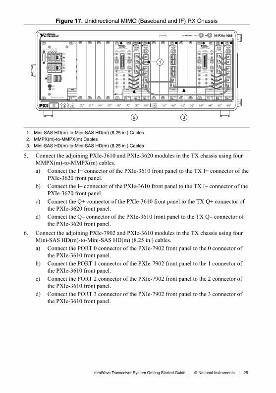
Figure 17. Unidirectional MIMO (Baseband and IF) RX Chassis
NI PXIe-3620IF-LO Module, 2 GHz BW
TX
LO1IN
LO1
IF OUT IF IN
IF SYNC INIF SYNC OUT
REF IN
REF OUT
LO2 OUT
ESDSENSITIVE
LO2 IN
I+
I–
Q+
Q–
I+
I–
Q+
Q–
DIGITAL I/OLVTTL
LO1
LO1OUT
LO1IN
LO1OUT
RXmmWave
PXIe-7902
CLKIN
PO
RT
2P
OR
T3
PO
RT
4P
OR
T5
PO
RT
0P
OR
T1
PXIe-3630I/Q Digitizer
REF IN
+10 dBmNOM
+13 dBmMAX
1.5 Vp-pDIFF MAX
1.5 Vp-pDIFF MAX
0 Vcm
ALL PORTS 50 Ω
REFOUT
0
1
2
3
Q+Q–
I+I–
ACCESS ACTIVE
21 3 4 5 6 7 8 9 11 12 13 14 15 16 17 1810
NI PXIe-108510 MHz REF OUT IN24 GB/s
Embedded Controller
RESET
TRIG
ACT/LINK
ACT/LINK
2
1
10/100/1000
10/100/1000
USER1USER2
PWR OK/FAULTDRIVEGPIB
PXIe-7902
CLKIN
PO
RT
2P
OR
T3
PO
RT
4P
OR
T5
PO
RT
0P
OR
T11
2 3
1. Mini-SAS HD(m)-to-Mini-SAS HD(m) (8.25 in.) Cables2. MMPX(m)-to-MMPX(m) Cables3. Mini-SAS HD(m)-to-Mini-SAS HD(m) (8.25 in.) Cables
5. Connect the adjoining PXIe-3610 and PXIe-3620 modules in the TX chassis using fourMMPX(m)-to-MMPX(m) cables.a) Connect the I+ connector of the PXIe-3610 front panel to the TX I+ connector of the
PXIe-3620 front panel.b) Connect the I– connector of the PXIe-3610 front panel to the TX I– connector of the
PXIe-3620 front panel.c) Connect the Q+ connector of the PXIe-3610 front panel to the TX Q+ connector of
the PXIe-3620 front panel.d) Connect the Q– connector of the PXIe-3610 front panel to the TX Q– connector of
the PXIe-3620 front panel.6. Connect the adjoining PXIe-7902 and PXIe-3610 modules in the TX chassis using four
Mini-SAS HD(m)-to-Mini-SAS HD(m) (8.25 in.) cables.a) Connect the PORT 0 connector of the PXIe-7902 front panel to the 0 connector of
the PXIe-3610 front panel.b) Connect the PORT 1 connector of the PXIe-7902 front panel to the 1 connector of
the PXIe-3610 front panel.c) Connect the PORT 2 connector of the PXIe-7902 front panel to the 2 connector of
the PXIe-3610 front panel.d) Connect the PORT 3 connector of the PXIe-7902 front panel to the 3 connector of
the PXIe-3610 front panel.
mmWave Transceiver System Getting Started Guide | © National Instruments | 25
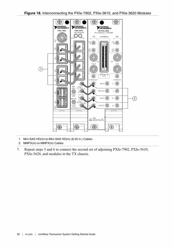
Figure 18. Interconnecting the PXIe-7902, PXIe-3610, and PXIe-3620 Modules
PXIe-3610I/Q Generator
0
1
2
3
REF IN
+10 dBmNOM
+13 dBmMAX
2 Vp-pDIFF MAX
2 Vp-pDIFF MAX
0 Vcm
ALL PORTS 50 Ω
REFOUT
Q+Q–
I+I–
ACCESS ACTIVE
PXIe-7902
PO
RT
4P
OR
T5
PO
RT
2P
OR
T3
PO
RT
0P
OR
T1
CLKIN
NI PXIe-3620IF-LO Module, 2 GHz BW
TX
LO1IN
LO1
IF OUT IF IN
IF SYNC INIF SYNC OUT
REF IN
REF OUT
LO2 OUT
ESDSENSITIVE
LO2 IN
I+
I–
Q+
Q–
I+
I–
Q+
Q–
DIGITAL I/OLVTTL
LO1
LO1OUT
LO1IN
LO1OUT
RXmmWave
2
1
1. Mini-SAS HD(m)-to-Mini-SAS HD(m) (8.25 in.) Cables2. MMPX(m)-to-MMPX(m) Cables
7. Repeat steps 5 and 6 to connect the second set of adjoining PXIe-7902, PXIe-3610,PXIe-3620, and modules in the TX chassis.
26 | ni.com | mmWave Transceiver System Getting Started Guide

Figure 19. Unidirectional MIMO (Baseband and IF) TX Chassis
21 3 4 5 6 7 8 9 11 12 13 14 15 16 17 1810
NI PXIe-108510 MHz REF OUT IN24 GB/s
Embedded Controller
RESET
TRIG
ACT/LINK
ACT/LINK
2
1
10/100/1000
10/100/1000
USER1USER2
PWR OK/FAULTDRIVEGPIB
NI PXIe-3620IF-LO Module, 2 GHz BW
TX
LO1IN
LO1
IF OUT IF IN
IF SYNC INIF SYNC OUT
REF IN
REF OUT
LO2 OUT
ESDSENSITIVE
LO2 IN
I+
I–
Q+
Q–
I+
I–
Q+
Q–
DIGITAL I/OLVTTL
LO1
LO1OUT
LO1IN
LO1OUT
RXmmWave
PXIe-7902
PO
RT
4P
OR
T5
PO
RT
2P
OR
T3
PO
RT
0P
OR
T1
CLKIN
PXIe-3610I/Q Generator
0
1
2
3
REF IN
+10 dBmNOM
+13 dBmMAX
2 Vp-pDIFF MAX
2 Vp-pDIFF MAX
0 Vcm
ALL PORTS 50 Ω
REFOUT
Q+Q–
I+I–
ACCESS ACTIVE
2
1
1. Mini-SAS HD(m)-to-Mini-SAS HD(m) (8.25 in.) Cables2. MMPX(m)-to-MMPX(m) Cables
8. Repeat steps 1 through 6 for the second set of chassis.
Related Information
Connecting mmRH-3642/3643/3652/3653 Radio Heads to a Unidirectional System on page39
Connecting mmRH-3647/3657 Radio Heads to a Unidirectional System on page 42
Configuring the Coding Modules of a MIMO System on page 50
Bidirectional System SetupThis section describes how to connect the modules of a bidirectional mmWave TransceiverSystem.
Bidirectional mmWave Transceiver System configurations are as follows:• Bidirectional SISO (baseband)• Bidirectional SISO (baseband and IF)• Bidirectional MIMO (baseband)• Bidirectional MIMO (baseband and IF)
Each configuration consists of two RX/TX chassis with identical module configurations.
Interconnecting the Bidirectional SISO (Baseband) ModulesComplete the following steps to connect the modules of the bidirectional SISO (baseband)mmWave Transceiver System configuration.1. Connect the adjoining PXIe-7902 and PXIe-3610 modules using four Mini-SAS HD(m)-
to-Mini-SAS HD(m) (8.25 in.) cables.a) Connect the PORT 0 connector of the PXIe-7902 front panel to the 0 connector of
the PXIe-3610 front panel.
mmWave Transceiver System Getting Started Guide | © National Instruments | 27

b) Connect the PORT 1 connector of the PXIe-7902 front panel to the 1 connector ofthe PXIe-3610 front panel.
c) Connect the PORT 2 connector of the PXIe-7902 front panel to the 2 connector ofthe PXIe-3610 front panel.
d) Connect the PORT 3 connector of the PXIe-7902 front panel to the 3 connector ofthe PXIe-3610 front panel.
Figure 20. Interconnecting the PXIe-7902 and PXIe-3610 Modules
PXIe-3610I/Q Generator
PXIe-7902
0
1
2
3
REF IN
+10 dBmNOM
+13 dBmMAX
2 Vp-pDIFF MAX
2 Vp-pDIFF MAX
0 Vcm
ALL PORTS 50 Ω
REFOUT
Q+Q–
I+I–
PO
RT
4P
OR
T5
PO
RT
2P
OR
T3
PO
RT
0P
OR
T1
ACCESS ACTIVE
CLKIN
1
1. Mini-SAS HD(m)-to-Mini-SAS HD(m) (8.25 in.) Cables
2. Connect the adjoining PXIe-3630 and PXIe-7902 modules using four Mini-SAS HD(m)-to-Mini-SAS HD(m) (8.25 in.) cables.a) Connect the 0 connector of the PXIe-3630 front panel to the PORT 0 connector of
the PXIe-7902 front panel.b) Connect the 1 connector of the PXIe-3630 front panel to the PORT 1 connector of
the PXIe-7902 front panel.c) Connect the 2 connector of the PXIe-3630 front panel to the PORT 2 connector of
the PXIe-7902 front panel.d) Connect the 3 connector of the PXIe-3630 front panel to the PORT 3 connector of
the PXIe-7902 front panel.3. Connect the PORT 4 connector of the PXIe-7902 front panel to the PORT 4 connector of
the second PXIe-7902 front panel.
28 | ni.com | mmWave Transceiver System Getting Started Guide

Figure 21. Bidirectional SISO (Baseband) Chassis
PXIe-7902
CLKIN
PO
RT
2P
OR
T3
PO
RT
4P
OR
T5
PO
RT
0P
OR
T1
PXIe-3630I/Q Digitizer
REF IN
+10 dBmNOM
+13 dBmMAX
1.5 Vp-pDIFF MAX
1.5 Vp-pDIFF MAX
0 Vcm
ALL PORTS 50 Ω
REFOUT
0
1
2
3
Q+Q–
I+I–
ACCESS ACTIVE
21 3 4 5 6 7 8 9 11 12 13 14 15 16 17 1810
NI PXIe-108510 MHz REF OUT IN24 GB/s
Embedded Controller
RESET
TRIG
ACT/LINK
ACT/LINK
2
1
10/100/1000
10/100/1000
USER1USER2
PWR OK/FAULTDRIVEGPIB
PXIe-7902
PO
RT
4P
OR
T5
PO
RT
2P
OR
T3
PO
RT
0P
OR
T1
CLKIN
PXIe-3610I/Q Generator
0
1
2
3
REF IN
+10 dBmNOM
+13 dBmMAX
2 Vp-pDIFF MAX
2 Vp-pDIFF MAX
0 Vcm
ALL PORTS 50 Ω
REFOUT
Q+Q–
I+I–
ACCESS ACTIVE
PXIe-7902
CLKIN
PO
RT
2P
OR
T3
PO
RT
4P
OR
T5
PO
RT
0P
OR
T1
2
1
1. Mini-SAS HD(m)-to-Mini-SAS HD(m) (8.25 in.) Cables2. Mini-SAS HD(m)-to-Mini-SAS HD(m) (8.25 in.) Cable
4. Repeat steps 1 through 3 for the second RX/TX chassis.
Disconnect cables or otherwise attenuate the signal to ensure that no signal is entering thebaseband ports on the PXIe-3630 module during system startup.
Interconnecting the Bidirectional SISO (Baseband and IF)ModulesComplete the following steps to connect the modules of the bidirectional SISO (baseband andIF) mmWave Transceiver System configuration.1. Connect the adjoining PXIe-3610 and PXIe-3620 modules using four MMPX(m)-to-
MMPX(m) cables.a) Connect the I+ connector of the PXIe-3610 front panel to the TX I+ connector of the
PXIe-3620 front panel.b) Connect the I– connector of the PXIe-3610 front panel to the TX I– connector of the
PXIe-3620 front panel.c) Connect the Q+ connector of the PXIe-3610 front panel to the TX Q+ connector of
the PXIe-3620 front panel.d) Connect the Q– connector of the PXIe-3610 front panel to the TX Q– connector of
the PXIe-3620 front panel.2. Connect the adjoining PXIe-3620 and PXIe-3630 modules using four MMPX(m)-to-
MMPX(m) cables.a) Connect the RX I+ connector of the PXIe-3620 front panel to the I+ connector of the
PXIe-3630 front panel.b) Connect the RX I– connector of the PXIe-3620 front panel to the I– connector of the
PXIe-3630 front panel.c) Connect the RX Q+ connector of the PXIe-3620 front panel to the Q+ connector of
the PXIe-3630 front panel.d) Connect the RX Q– connector of the PXIe-3620 front panel to the Q– connector of
the PXIe-3630 front panel.
mmWave Transceiver System Getting Started Guide | © National Instruments | 29

3. Connect the adjoining PXIe-7902 and PXIe-3610 modules using four Mini-SAS HD(m)-to-Mini-SAS HD(m) (8.25 in.) cables.a) Connect the PORT 0 connector of the PXIe-7902 front panel to the 0 connector of
the PXIe-3610 front panel.b) Connect the PORT 1 connector of the PXIe-7902 front panel to the 1 connector of
the PXIe-3610 front panel.c) Connect the PORT 2 connector of the PXIe-7902 front panel to the 2 connector of
the PXIe-3610 front panel.d) Connect the PORT 3 connector of the PXIe-7902 front panel to the 3 connector of
the PXIe-3610 front panel.4. Connect the adjoining PXIe-3630 and PXIe-7902 modules using four Mini-SAS HD(m)-
to-Mini-SAS HD(m) (8.25 in.) cables.a) Connect the 0 connector of the PXIe-3630 front panel to the PORT 0 connector of
the PXIe-7902 front panel.b) Connect the 1 connector of the PXIe-3630 front panel to the PORT 1 connector of
the PXIe-7902 front panel.c) Connect the 2 connector of the PXIe-3630 front panel to the PORT 2 connector of
the PXIe-7902 front panel.d) Connect the 3 connector of the PXIe-3630 front panel to the PORT 3 connector of
the PXIe-7902 front panel.
30 | ni.com | mmWave Transceiver System Getting Started Guide
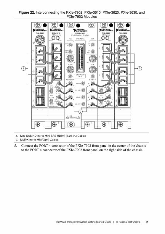
Figure 22. Interconnecting the PXIe-7902, PXIe-3610, PXIe-3620, PXIe-3630, andPXIe-7902 Modules
PXIe-3610I/Q Generator
PXIe-7902
0
1
2
3
REF IN
+10 dBmNOM
+13 dBmMAX
2 Vp-pDIFF MAX
2 Vp-pDIFF MAX
0 Vcm
ALL PORTS 50 Ω
REFOUT
Q+Q–
I+I–
PO
RT
4P
OR
T5
PO
RT
2P
OR
T3
PO
RT
0P
OR
T1
ACCESS ACTIVE
CLKIN
NI PXIe-3620IF-LO Module, 2 GHz BW
TX
LO1IN
LO1
IF OUT IF IN
IF SYNC INIF SYNC OUT
REF IN
REF OUT
LO2 OUT
ESDSENSITIVE
LO2 IN
I+
I–
Q+
Q–
I+
I–
Q+
Q–
DIGITAL I/OLVTTL
LO1
LO1OUT
LO1IN
LO1OUT
RXmmWave
PXIe-3630I/Q Digitizer
REF IN
+10 dBmNOM
+13 dBmMAX
1.5 Vp-pDIFF MAX
1.5 Vp-pDIFF MAX
0 Vcm
ALL PORTS 50 Ω
REFOUT
0
1
2
3
Q+Q–
I+I–
ACCESS ACTIVE
PXIe-7902
CLKIN
PO
RT
2P
OR
T3
PO
RT
4P
OR
T5
PO
RT
0P
OR
T1
2
1 1
1. Mini-SAS HD(m)-to-Mini-SAS HD(m) (8.25 in.) Cables2. MMPX(m)-to-MMPX(m) Cables
5. Connect the PORT 4 connector of the PXIe-7902 front panel in the center of the chassisto the PORT 4 connector of the PXIe-7902 front panel on the right side of the chassis.
mmWave Transceiver System Getting Started Guide | © National Instruments | 31

Figure 23. Bidirectional SISO (Baseband and IF) Chassis
NI PXIe-3620IF-LO Module, 2 GHz BW
TX
LO1IN
LO1
IF OUT IF IN
IF SYNC INIF SYNC OUT
REF IN
REF OUT
LO2 OUT
ESDSENSITIVE
LO2 IN
I+
I–
Q+
Q–
I+
I–
Q+
Q–
DIGITAL I/OLVTTL
LO1
LO1OUT
LO1IN
LO1OUT
RXmmWave
PXIe-7902
PO
RT
4P
OR
T5
PO
RT
2P
OR
T3
PO
RT
0P
OR
T1
CLKIN
PXIe-3610I/Q Generator
0
1
2
3
REF IN
+10 dBmNOM
+13 dBmMAX
2 Vp-pDIFF MAX
2 Vp-pDIFF MAX
0 Vcm
ALL PORTS 50 Ω
REFOUT
Q+Q–
I+I–
ACCESS ACTIVE
PXIe-7902
CLKIN
PO
RT
2P
OR
T3
PO
RT
4P
OR
T5
PO
RT
0P
OR
T1
PXIe-3630I/Q Digitizer
REF IN
+10 dBmNOM
+13 dBmMAX
1.5 Vp-pDIFF MAX
1.5 Vp-pDIFF MAX
0 Vcm
ALL PORTS 50 Ω
REFOUT
0
1
2
3
Q+Q–
I+I–
ACCESS ACTIVE
21 3 4 5 6 7 8 9 11 12 13 14 15 16 17 1810
NI PXIe-108510 MHz REF OUT IN24 GB/s
Embedded Controller
RESET
TRIG
ACT/LINK
ACT/LINK
2
1
10/100/1000
10/100/1000
USER1USER2
PWR OK/FAULTDRIVEGPIB
PXIe-7902
CLKIN
PO
RT
2P
OR
T3
PO
RT
4P
OR
T5
PO
RT
0P
OR
T1
1
23
1. Mini-SAS HD(m)-to-Mini-SAS HD(m) (8.25 in.) Cables2. MMPX(m)-to-MMPX(m) Cables3. Mini-SAS HD(m)-to-Mini-SAS HD(m) (8.25 in.) Cable
6. Repeat steps 1 through 5 for the second RX/TX chassis.
Related Information
Connecting mmRH-3602/3603 Radio Heads to a Bidirectional System on page 44
Connecting mmRH-3642/3643/3652/3653 Radio Heads to a Bidirectional System on page 47
Connecting mmRH-3647/3657 Radio Heads to a Bidirectional System on page 49
Interconnecting the Bidirectional MIMO (Baseband) ModulesComplete the following steps to connect the modules of the bidirectional MIMO (baseband)mmWave Transceiver System configuration.1. Connect the adjoining PXIe-7902 and PXIe-3610 modules using four Mini-SAS HD(m)-
to-Mini-SAS HD(m) (8.25 in.) cables.a) Connect the PORT 0 connector of the PXIe-7902 front panel to the 0 connector of
the PXIe-3610 front panel.b) Connect the PORT 1 connector of the PXIe-7902 front panel to the 1 connector of
the PXIe-3610 front panel.c) Connect the PORT 2 connector of the PXIe-7902 front panel to the 2 connector of
the PXIe-3610 front panel.d) Connect the PORT 3 connector of the PXIe-7902 front panel to the 3 connector of
the PXIe-3610 front panel.
32 | ni.com | mmWave Transceiver System Getting Started Guide

Figure 24. Interconnecting the PXIe-7902 and PXIe-3610 Modules
PXIe-3610I/Q Generator
PXIe-7902
0
1
2
3
REF IN
+10 dBmNOM
+13 dBmMAX
2 Vp-pDIFF MAX
2 Vp-pDIFF MAX
0 Vcm
ALL PORTS 50 Ω
REFOUT
Q+Q–
I+I–
PO
RT
4P
OR
T5
PO
RT
2P
OR
T3
PO
RT
0P
OR
T1
ACCESS ACTIVE
CLKIN
1
1. Mini-SAS HD(m)-to-Mini-SAS HD(m) (8.25 in.) Cables
2. Repeat step 1 to connect the second set of adjoining PXIe-7902 and PXIe-3610 modules.3. Connect the adjoining PXIe-3630 and PXIe-7902 modules using four Mini-SAS HD(m)-
to-Mini-SAS HD(m) (8.25 in.) cables.a) Connect the 0 connector of the PXIe-3630 front panel to the PORT 0 connector of
the PXIe-7902 front panel.b) Connect the 1 connector of the PXIe-3630 front panel to the PORT 1 connector of
the PXIe-7902 front panel.c) Connect the 2 connector of the PXIe-3630 front panel to the PORT 2 connector of
the PXIe-7902 front panel.d) Connect the 3 connector of the PXIe-3630 front panel to the PORT 3 connector of
the PXIe-7902 front panel.
mmWave Transceiver System Getting Started Guide | © National Instruments | 33

Figure 25. Interconnecting the PXIe-3630 and PXIe-7902 Modules
PXIe-3630I/Q Digitizer
REF IN
+10 dBmNOM
+13 dBmMAX
1.5 Vp-pDIFF MAX
1.5 Vp-pDIFF MAX
0 Vcm
ALL PORTS 50 Ω
REFOUT
0
1
2
3
Q+Q–
I+I–
ACCESS ACTIVE
PXIe-7902
CLKIN
PO
RT
2P
OR
T4
PO
RT
5P
OR
T3
PO
RT
0P
OR
T1
1
1. Mini-SAS HD(m)-to-Mini-SAS HD(m) (8.25 in.) Cables
4. Repeat step 3 to connect the second set of adjoining PXIe-3630 and PXIe-7902 modules.5. Connect the PXIe-7902 modules in the chassis using three Mini-SAS HD(m)-to-Mini-
SAS HD(m) (8.25 in.) cables.a) Connect the PORT 4 connector of the PXIe-7902 front panel in slot 9 of the chassis
to the PORT 4 connector of the PXIe-7902 in slot 12 of the chassis.b) Connect the PORT 5 connector of the PXIe-7902 front panel in slot 9 of the chassis
to the PORT 5 connector of the PXIe-7902 in slot 18 of the chassis.c) Connect the PORT 5 connector of the PXIe-7902 front panel in slot 12 of the chassis
to the PORT 4 connector of the PXIe-7902 in slot 18 of the chassis.
34 | ni.com | mmWave Transceiver System Getting Started Guide

Figure 26. Bidirectional MIMO (Baseband) Chassis
PXIe-7902
PO
RT
4P
OR
T5
PO
RT
2P
OR
T3
PO
RT
0P
OR
T1
CLKIN
PXIe-3610I/Q Generator
0
1
2
3
REF IN
+10 dBmNOM
+13 dBmMAX
2 Vp-pDIFF MAX
2 Vp-pDIFF MAX
0 Vcm
ALL PORTS 50 Ω
REFOUT
Q+Q–
I+I–
ACCESS ACTIVE
PXIe-7902
PO
RT
4P
OR
T5
PO
RT
2P
OR
T3
PO
RT
0P
OR
T1
CLKIN
PXIe-3610I/Q Generator
0
1
2
3
REF IN
+10 dBmNOM
+13 dBmMAX
2 Vp-pDIFF MAX
2 Vp-pDIFF MAX
0 Vcm
ALL PORTS 50 Ω
REFOUT
Q+Q–
I+I–
ACCESS ACTIVE
PXIe-7902
CLKIN
PO
RT
2P
OR
T3
PO
RT
4P
OR
T5
PO
RT
0P
OR
T1
PXIe-3630I/Q Digitizer
REF IN
+10 dBmNOM
+13 dBmMAX
1.5 Vp-pDIFF MAX
1.5 Vp-pDIFF MAX
0 Vcm
ALL PORTS 50 Ω
REFOUT
0
1
2
3
Q+Q–
I+I–
ACCESS ACTIVE
PXIe-7902
CLKIN
PO
RT
2P
OR
T3
PO
RT
4P
OR
T5
PO
RT
0P
OR
T1
PXIe-3630I/Q Digitizer
REF IN
+10 dBmNOM
+13 dBmMAX
1.5 Vp-pDIFF MAX
1.5 Vp-pDIFF MAX
0 Vcm
ALL PORTS 50 Ω
REFOUT
0
1
2
3
Q+Q–
I+I–
ACCESS ACTIVE
21 3 4 5 6 7 8 9 11 12 13 14 15 16 17 1810
NI PXIe-108510 MHz REF OUT IN24 GB/s
Embedded Controller
RESET
TRIG
ACT/LINK
ACT/LINK
2
1
10/100/1000
10/100/1000
USER1USER2
PWR OK/FAULTDRIVEGPIB
PXIe-7902
CLKIN
PO
RT
2P
OR
T3
PO
RT
4P
OR
T5
PO
RT
0P
OR
T11
2
1. Mini-SAS HD(m)-to-Mini-SAS HD(m) (8.25 in.) Cables2. Mini-SAS HD(m)-to-Mini-SAS HD(m) (8.25 in.) Cables
6. Repeat steps 1 through 5 for the second RX/TX chassis.
Disconnect cables or otherwise attenuate the signal to ensure that no signal is entering thebaseband ports on the PXIe-3630 module during system startup.
Related Information
Configuring the Coding Modules of a MIMO System on page 50
Interconnecting the Bidirectional MIMO (Baseband and IF)ModulesComplete the following steps to connect the modules of the bidirectional MIMO (basebandand IF) mmWave Transceiver System configuration.1. Connect the adjoining PXIe-3610 and PXIe-3620 modules using four MMPX(m)-to-
MMPX(m) cables.a) Connect the I+ connector of the PXIe-3610 front panel to the TX I+ connector of the
PXIe-3620 front panel.b) Connect the I– connector of the PXIe-3610 front panel to the TX I– connector of the
PXIe-3620 front panel.c) Connect the Q+ connector of the PXIe-3610 front panel to the TX Q+ connector of
the PXIe-3620 front panel.d) Connect the Q– connector of the PXIe-3610 front panel to the TX Q– connector of
the PXIe-3620 front panel.2. Connect the adjoining PXIe-3620 and PXIe-3630 modules using four MMPX(m)-to-
MMPX(m) cables.a) Connect the RX I+ connector of the PXIe-3620 front panel to the I+ connector of the
PXIe-3630 front panel.b) Connect the RX I– connector of the PXIe-3620 front panel to the I– connector of the
PXIe-3630 front panel.
mmWave Transceiver System Getting Started Guide | © National Instruments | 35

c) Connect the RX Q+ connector of the PXIe-3620 front panel to the Q+ connector ofthe PXIe-3630 front panel.
d) Connect the RX Q– connector of the PXIe-3620 front panel to the Q– connector ofthe PXIe-3630 front panel.
3. Connect the adjoining PXIe-7902 and PXIe-3610 modules using four Mini-SAS HD(m)-to-Mini-SAS HD(m) (8.25 in.) cables.a) Connect the PORT 0 connector of the PXIe-7902 front panel to the 0 connector of
the PXIe-3610 front panel.b) Connect the PORT 1 connector of the PXIe-7902 front panel to the 1 connector of
the PXIe-3610 front panel.c) Connect the PORT 2 connector of the PXIe-7902 front panel to the 2 connector of
the PXIe-3610 front panel.d) Connect the PORT 3 connector of the PXIe-7902 front panel to the 3 connector of
the PXIe-3610 front panel.4. Connect the adjoining PXIe-3630 and PXIe-7902 modules using four Mini-SAS HD(m)-
to-Mini-SAS HD(m) (8.25 in.) cables.a) Connect the 0 connector of the PXIe-3630 front panel to the PORT 0 connector of
the PXIe-7902 front panel.b) Connect the 1 connector of the PXIe-3630 front panel to the PORT 1 connector of
the PXIe-7902 front panel.c) Connect the 2 connector of the PXIe-3630 front panel to the PORT 2 connector of
the PXIe-7902 front panel.d) Connect the 3 connector of the PXIe-3630 front panel to the PORT 3 connector of
the PXIe-7902 front panel.
36 | ni.com | mmWave Transceiver System Getting Started Guide

Figure 27. Interconnecting the PXIe-7902, PXIe-3610, PXIe-3620, PXIe-3630, andPXIe-7902 Modules
PXIe-3610I/Q Generator
PXIe-7902
0
1
2
3
REF IN
+10 dBmNOM
+13 dBmMAX
2 Vp-pDIFF MAX
2 Vp-pDIFF MAX
0 Vcm
ALL PORTS 50 Ω
REFOUT
Q+Q–
I+I–
PO
RT
4P
OR
T5
PO
RT
2P
OR
T3
PO
RT
0P
OR
T1
ACCESS ACTIVE
CLKIN
NI PXIe-3620IF-LO Module, 2 GHz BW
TX
LO1IN
LO1
IF OUT IF IN
IF SYNC INIF SYNC OUT
REF IN
REF OUT
LO2 OUT
ESDSENSITIVE
LO2 IN
I+
I–
Q+
Q–
I+
I–
Q+
Q–
DIGITAL I/OLVTTL
LO1
LO1OUT
LO1IN
LO1OUT
RXmmWave
PXIe-3630I/Q Digitizer
REF IN
+10 dBmNOM
+13 dBmMAX
1.5 Vp-pDIFF MAX
1.5 Vp-pDIFF MAX
0 Vcm
ALL PORTS 50 Ω
REFOUT
0
1
2
3
Q+Q–
I+I–
ACCESS ACTIVE
PXIe-7902
CLKIN
PO
RT
2P
OR
T3
PO
RT
4P
OR
T5
PO
RT
0P
OR
T1
2
1 1
1. Mini-SAS HD(m)-to-Mini-SAS HD(m) (8.25 in.) Cables2. MMPX(m)-to-MMPX(m) Cables
5. Repeat steps 1 through 4 to connect the second set of adjoining PXIe-7902, PXIe-3610,PXIe-3620, PXIe-3630, and PXIe-7902 modules.
6. Connect the PXIe-7902 modules in the chassis using three Mini-SAS HD(m)-to-Mini-SAS HD(m) (8.25 in.) cables.a) Connect the PORT 4 connector of the PXIe-7902 front panel in slot 9 of the chassis
to the PORT 4 connector of the PXIe-7902 in slot 12 of the chassis.b) Connect the PORT 5 connector of the PXIe-7902 front panel in slot 9 of the chassis
to the PORT 5 connector of the PXIe-7902 in slot 18 of the chassis.c) Connect the PORT 5 connector of the PXIe-7902 front panel in slot 12 of the chassis
to the PORT 4 connector of the PXIe-7902 in slot 18 of the chassis.
mmWave Transceiver System Getting Started Guide | © National Instruments | 37
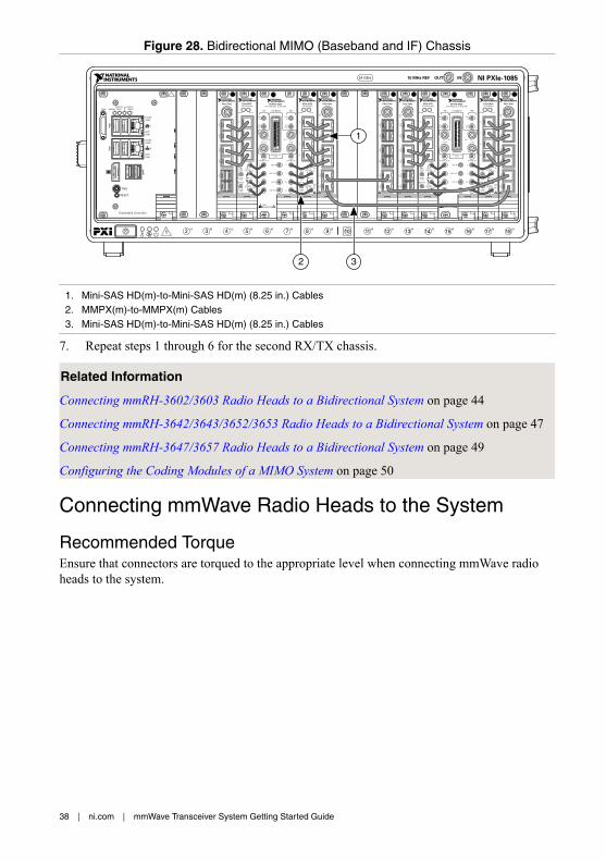
Figure 28. Bidirectional MIMO (Baseband and IF) Chassis
NI PXIe-3620IF-LO Module, 2 GHz BW
TX
LO1IN
LO1
IF OUT IF IN
IF SYNC INIF SYNC OUT
REF IN
REF OUT
LO2 OUT
ESDSENSITIVE
LO2 IN
I+
I–
Q+
Q–
I+
I–
Q+
Q–
DIGITAL I/OLVTTL
LO1
LO1OUT
LO1IN
LO1OUT
RXmmWave
PXIe-7902
PO
RT
4P
OR
T5
PO
RT
2P
OR
T3
PO
RT
0P
OR
T1
CLKIN
PXIe-3610I/Q Generator
0
1
2
3
REF IN
+10 dBmNOM
+13 dBmMAX
2 Vp-pDIFF MAX
2 Vp-pDIFF MAX
0 Vcm
ALL PORTS 50 Ω
REFOUT
Q+Q–
I+I–
ACCESS ACTIVE
PXIe-7902
CLKIN
PO
RT
2P
OR
T3
PO
RT
4P
OR
T5
PO
RT
0P
OR
T1
PXIe-3630I/Q Digitizer
REF IN
+10 dBmNOM
+13 dBmMAX
1.5 Vp-pDIFF MAX
1.5 Vp-pDIFF MAX
0 Vcm
ALL PORTS 50 Ω
REFOUT
0
1
2
3
Q+Q–
I+I–
ACCESS ACTIVE
21 3 4 5 6 7 8 9 11 12 13 14 15 16 17 1810
NI PXIe-108510 MHz REF OUT IN24 GB/s
Embedded Controller
RESET
TRIG
ACT/LINK
ACT/LINK
2
1
10/100/1000
10/100/1000
USER1USER2
PWR OK/FAULTDRIVEGPIB
PXIe-7902
CLKIN
PO
RT
2P
OR
T3
PO
RT
4P
OR
T5
PO
RT
0P
OR
T11
2 3
1. Mini-SAS HD(m)-to-Mini-SAS HD(m) (8.25 in.) Cables2. MMPX(m)-to-MMPX(m) Cables3. Mini-SAS HD(m)-to-Mini-SAS HD(m) (8.25 in.) Cables
7. Repeat steps 1 through 6 for the second RX/TX chassis.
Related Information
Connecting mmRH-3602/3603 Radio Heads to a Bidirectional System on page 44
Connecting mmRH-3642/3643/3652/3653 Radio Heads to a Bidirectional System on page 47
Connecting mmRH-3647/3657 Radio Heads to a Bidirectional System on page 49
Configuring the Coding Modules of a MIMO System on page 50
Connecting mmWave Radio Heads to the System
Recommended TorqueEnsure that connectors are torqued to the appropriate level when connecting mmWave radioheads to the system.
38 | ni.com | mmWave Transceiver System Getting Started Guide

Table 6. Recommended Connector Torque
Connector Type Recommended Torque
2.4 mm 0.9 N∙m (8 in.∙lb)
2.92 mm 0.9 N∙m (8 in.∙lb)
3.5 mm (SMA) 0.9 N∙m (8 in.∙lb)
Related Information
mmRH-3602 Front/Back Panel and LEDs on page 68
mmRH-3603 Front/Back Panel and LEDs on page 71
mmRH-3642 Front/Back Panel and LEDs on page 74
mmRH-3643 Front/Back Panel and LEDs on page 76
mmRH-3647 Front/Back Panel and LEDs on page 78
mmRH-3652 Front/Back Panel and LEDs on page 80
mmRH-3653 Front/Back Panel and LEDs on page 82
mmRH-3657 Front/Back Panel and LEDs on page 84
Connecting mmWave Radio Heads to a Unidirectional System
Connecting mmRH-3642/3643/3652/3653 Radio Heads to a UnidirectionalSystemComplete the following steps to connect mmRH-3642/3643/3652/3653 radio heads to aunidirectional mmWave Transceiver System.
Note Connect the modules of the mmWave Transceiver System for standard usebefore connecting mmRH-3642/3643/3652/3653 radio heads.
1. Connect the RX chassis to the mmRH-3652/3653.a) Connect the DIGITAL I/O connector of the PXIe-3620 front panel in the RX chassis
to the DIO adapter module using an EPLSP cable.b) Connect the DIO adapter module to the DIO 1 connector1 of the mmRH-3652/3653
back panel using an HDMI(m)-to-mini-HDMI(m) cable.c) Connect the RX LO1 connector of the PXIe-3620 front panel in the RX chassis to
the LO IN RX connector of the mmRH-3652/3653 back panel using an SMA(m)-to-SMA(m) cable.
d) Connect the RX IF IN connector of the PXIe-3620 front panel in the RX chassis tothe IF OUT connector of the mmRH-3652/3653 back panel using an SMA(m)-to-SMA(m) cable.
1 You may connect the DIO adapter module to the DIO 0 connector instead of the DIO 1 connector.The choice of connector does not affect results.
mmWave Transceiver System Getting Started Guide | © National Instruments | 39

Figure 29. Connecting the mmRH-3652/3653 to the Unidirectional SISO (Baseband andIF) RX Chassis
NI PXIe-3620IF-LO Module, 2 GHz BW
TX
LO1IN
LO1
IF OUT IF IN
IF SYNC INIF SYNC OUT
REF IN
REF OUT
LO2 OUT
ESDSENSITIVE
LO2 IN
I+
I–
Q+
Q–
I+
I–
Q+
Q–
DIGITAL I/OLVTTL
LO1
LO1OUT
LO1IN
LO1OUT
RXmmWave
PXIe-7902
CLKIN
PO
RT
2P
OR
T3
PO
RT
4P
OR
T5
PO
RT
0P
OR
T1
PXIe-3630I/Q Digitizer
REF IN
+10 dBmNOM
+13 dBmMAX
1.5 Vp-pDIFF MAX
1.5 Vp-pDIFF MAX
0 Vcm
ALL PORTS 50 Ω
REFOUT
0
1
2
3
Q+Q–
I+I–
ACCESS ACTIVE
21 3 4 5 6 7 8 9 11 12 13 14 15 16 17 1810
NI PXIe-108510 MHz REF OUT IN24 GB/s
Embedded Controller
RESET
TRIG
ACT/LINK
ACT/LINK
2
1
10/100/1000
10/100/1000
USER1USER2
PWR OK/FAULTDRIVEGPIB
PXIe-7902
CLKIN
PO
RT
2P
OR
T3
PO
RT
4P
OR
T5
PO
RT
0P
OR
T1
7
54
1
2 3
8
6
LO IN RXIF OUT
+12 dBm MAX
DIO 1 DIO 0
ACTIVE ACCESS
50ΩCoupling Torque90 N-cm / 8 lbf-in
Input Damage LevelLO: +9 dBm
12 V 2.5A MAX
1. Mini-SAS HD(m)-to-Mini-SAS HD(m) (8.25 in.)Cables
2. MMPX(m)-to-MMPX(m) Cables3. Mini-SAS HD(m)-to-Mini-SAS HD(m) (8.25 in.)
Cable4. SMA(m)-to-SMA(m) Cable
5. SMA(m)-to-SMA(m) Cable6. EPLSP Cable7. DIO Adapter Module8. HDMI(m)-to-mini-HDMI(m) Cable
e) If you have a MIMO system, repeat steps a through d for the second PXIe-3620module in the RX chassis and a second mmRH-3652/3653.
2. Connect the TX chassis to the mmRH-3642/3643.a) Connect the DIGITAL I/O connector of the PXIe-3620 front panel in the TX chassis
to the DIO adapter module using an EPLSP cable.b) Connect the DIO adapter module to the DIO 1 connector2 of the mmRH-3642/3643
back panel using an HDMI(m)-to-mini-HDMI(m) cable.c) Connect the TX LO1 connector of the PXIe-3620 front panel in the TX chassis to
the LO IN TX connector of the mmRH-3642/3643 back panel using an SMA(m)-to-SMA(m) cable.
2 You may connect the DIO adapter module to the DIO 0 connector instead of the DIO 1 connector.The choice of connector does not affect results.
40 | ni.com | mmWave Transceiver System Getting Started Guide
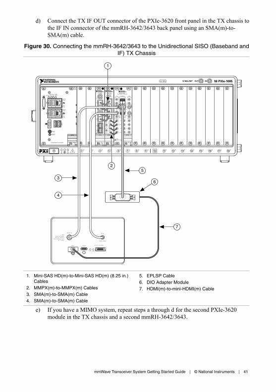
d) Connect the TX IF OUT connector of the PXIe-3620 front panel in the TX chassis tothe IF IN connector of the mmRH-3642/3643 back panel using an SMA(m)-to-SMA(m) cable.
Figure 30. Connecting the mmRH-3642/3643 to the Unidirectional SISO (Baseband andIF) TX Chassis
LO IN TXIF IN
0 dBm MAX
DIO 1 DIO 0
ACTIVE ACCESS
50ΩCoupling Torque90 N-cm / 8 lbf-in
Input Damage LevelLO: +9 dBm
12 V 2.5A MAX
21 3 4 5 6 7 8 9 11 12 13 14 15 16 17 1810
NI PXIe-108510 MHz REF OUT IN24 GB/s
Embedded Controller
RESET
TRIG
ACT/LINK
ACT/LINK
2
1
10/100/1000
10/100/1000
USER1USER2
PWR OK/FAULTDRIVEGPIB
NI PXIe-3620IF-LO Module, 2 GHz BW
TX
LO1IN
LO1
IF OUT IF IN
IF SYNC INIF SYNC OUT
REF IN
REF OUT
LO2 OUT
ESDSENSITIVE
LO2 IN
I+
I–
Q+
Q–
I+
I–
Q+
Q–
DIGITAL I/OLVTTL
LO1
LO1OUT
LO1IN
LO1OUT
RXmmWave
PXIe-7902
PO
RT
4P
OR
T5
PO
RT
2P
OR
T3
PO
RT
0P
OR
T1
CLKIN
PXIe-3610I/Q Generator
0
1
2
3
REF IN
+10 dBmNOM
+13 dBmMAX
2 Vp-pDIFF MAX
2 Vp-pDIFF MAX
0 Vcm
ALL PORTS 50 Ω
REFOUT
Q+Q–
I+I–
ACCESS ACTIVE
5
6
7
1
2
3
4
1. Mini-SAS HD(m)-to-Mini-SAS HD(m) (8.25 in.)Cables
2. MMPX(m)-to-MMPX(m) Cables3. SMA(m)-to-SMA(m) Cable4. SMA(m)-to-SMA(m) Cable
5. EPLSP Cable6. DIO Adapter Module7. HDMI(m)-to-mini-HDMI(m) Cable
e) If you have a MIMO system, repeat steps a through d for the second PXIe-3620module in the TX chassis and a second mmRH-3642/3643.
mmWave Transceiver System Getting Started Guide | © National Instruments | 41

3. Connect all mmWave radio heads to power.
Related Information
Interconnecting the Unidirectional MIMO (Baseband and IF) Modules on page 23
Interconnecting the Unidirectional SISO (Baseband and IF) Modules on page 15
Connecting mmRH-3647/3657 Radio Heads to a Unidirectional SystemComplete the following steps to connect mmRH-3647/3657 radio heads to a unidirectionalmmWave Transceiver System.
Note Connect the modules of the mmWave Transceiver System for standard usebefore connecting mmRH-3647/3657 radio heads.
1. Connect the RX chassis to the mmRH-3657.a) Connect the DIGITAL I/O connector of the PXIe-3620 front panel in the RX chassis
to the CONTROL connector of the mmRH-3657 back panel using an EPLSP cable.b) Connect the RX LO1 connector of the PXIe-3620 front panel in the RX chassis to
the LO IN connector of the mmRH-3657 back panel using an SMA(m)-to-SMA(m)cable.
c) Connect the RX IF IN connector of the PXIe-3620 front panel in the RX chassis tothe IF OUT connector of the mmRH-3657 back panel using an SMA(m)-to-SMA(m)cable.
42 | ni.com | mmWave Transceiver System Getting Started Guide
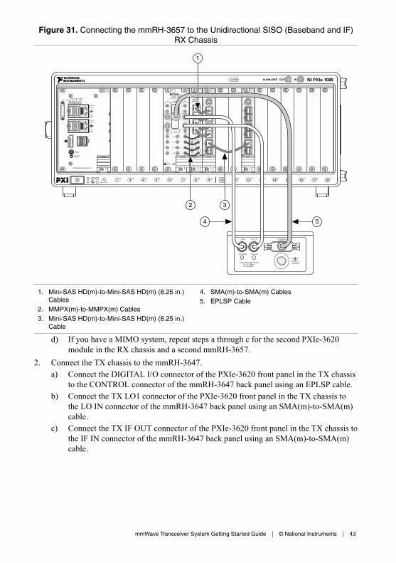
Figure 31. Connecting the mmRH-3657 to the Unidirectional SISO (Baseband and IF)RX Chassis
NI PXIe-3620IF-LO Module, 2 GHz BW
TX
LO1IN
LO1
IF OUT IF IN
IF SYNC INIF SYNC OUT
REF IN
REF OUT
LO2 OUT
ESDSENSITIVE
LO2 IN
I+
I–
Q+
Q–
I+
I–
Q+
Q–
DIGITAL I/OLVTTL
LO1
LO1OUT
LO1IN
LO1OUT
RXmmWave
PXIe-7902
CLKIN
PO
RT
2P
OR
T3
PO
RT
4P
OR
T5
PO
RT
0P
OR
T1
PXIe-3630I/Q Digitizer
REF IN
+10 dBmNOM
+13 dBmMAX
1.5 Vp-pDIFF MAX
1.5 Vp-pDIFF MAX
0 Vcm
ALL PORTS 50 Ω
REFOUT
0
1
2
3
Q+Q–
I+I–
ACCESS ACTIVE
21 3 4 5 6 7 8 9 11 12 13 14 15 16 17 1810
NI PXIe-108510 MHz REF OUT IN24 GB/s
Embedded Controller
RESET
TRIG
ACT/LINK
ACT/LINK
2
1
10/100/1000
10/100/1000
USER1USER2
PWR OK/FAULTDRIVEGPIB
PXIe-7902
CLKIN
PO
RT
2P
OR
T3
PO
RT
4P
OR
T5
PO
RT
0P
OR
T1
CONTROLLO IN
ACCESS
Input Damage Levels:LO: +12 dBmIF: –20 dBm
IF OUT
ACTIVE
2A MAX12 V
5
1
2 3
4
1. Mini-SAS HD(m)-to-Mini-SAS HD(m) (8.25 in.)Cables
2. MMPX(m)-to-MMPX(m) Cables3. Mini-SAS HD(m)-to-Mini-SAS HD(m) (8.25 in.)
Cable
4. SMA(m)-to-SMA(m) Cables5. EPLSP Cable
d) If you have a MIMO system, repeat steps a through c for the second PXIe-3620module in the RX chassis and a second mmRH-3657.
2. Connect the TX chassis to the mmRH-3647.a) Connect the DIGITAL I/O connector of the PXIe-3620 front panel in the TX chassis
to the CONTROL connector of the mmRH-3647 back panel using an EPLSP cable.b) Connect the TX LO1 connector of the PXIe-3620 front panel in the TX chassis to
the LO IN connector of the mmRH-3647 back panel using an SMA(m)-to-SMA(m)cable.
c) Connect the TX IF OUT connector of the PXIe-3620 front panel in the TX chassis tothe IF IN connector of the mmRH-3647 back panel using an SMA(m)-to-SMA(m)cable.
mmWave Transceiver System Getting Started Guide | © National Instruments | 43
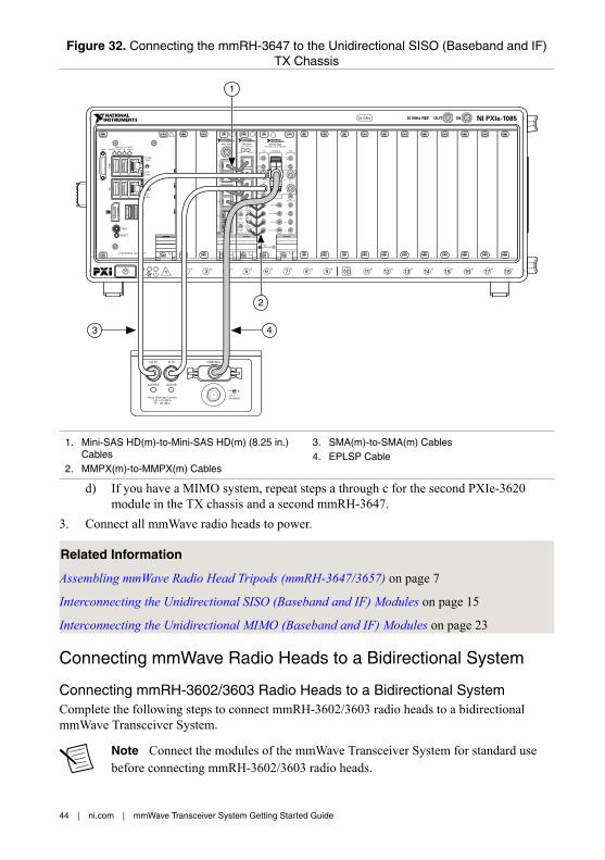
Figure 32. Connecting the mmRH-3647 to the Unidirectional SISO (Baseband and IF)TX Chassis
21 3 4 5 6 7 8 9 11 12 13 14 15 16 17 1810
NI PXIe-108510 MHz REF OUT IN24 GB/s
Embedded Controller
RESET
TRIG
ACT/LINK
ACT/LINK
2
1
10/100/1000
10/100/1000
USER1USER2
PWR OK/FAULTDRIVEGPIB
NI PXIe-3620IF-LO Module, 2 GHz BW
TX
LO1IN
LO1
IF OUT IF IN
IF SYNC INIF SYNC OUT
REF IN
REF OUT
LO2 OUT
ESDSENSITIVE
LO2 IN
I+
I–
Q+
Q–
I+
I–
Q+
Q–
DIGITAL I/OLVTTL
LO1
LO1OUT
LO1IN
LO1OUT
RXmmWave
PXIe-7902
PO
RT
4P
OR
T5
PO
RT
2P
OR
T3
PO
RT
0P
OR
T1
CLKIN
PXIe-3610I/Q Generator
0
1
2
3
REF IN
+10 dBmNOM
+13 dBmMAX
2 Vp-pDIFF MAX
2 Vp-pDIFF MAX
0 Vcm
ALL PORTS 50 Ω
REFOUT
Q+Q–
I+I–
ACCESS ACTIVE
CONTROLLO IN
ACCESS
Input Damage Levels:LO: +12 dBmIF: –20 dBm
IF IN
ACTIVE
2A MAX12 V
1
2
3 4
1. Mini-SAS HD(m)-to-Mini-SAS HD(m) (8.25 in.)Cables
2. MMPX(m)-to-MMPX(m) Cables
3. SMA(m)-to-SMA(m) Cables4. EPLSP Cable
d) If you have a MIMO system, repeat steps a through c for the second PXIe-3620module in the TX chassis and a second mmRH-3647.
3. Connect all mmWave radio heads to power.
Related Information
Assembling mmWave Radio Head Tripods (mmRH-3647/3657) on page 7
Interconnecting the Unidirectional SISO (Baseband and IF) Modules on page 15
Interconnecting the Unidirectional MIMO (Baseband and IF) Modules on page 23
Connecting mmWave Radio Heads to a Bidirectional System
Connecting mmRH-3602/3603 Radio Heads to a Bidirectional SystemComplete the following steps to connect mmRH-3602/3603 radio heads to a bidirectionalmmWave Transceiver System.
Note Connect the modules of the mmWave Transceiver System for standard usebefore connecting mmRH-3602/3603 radio heads.
44 | ni.com | mmWave Transceiver System Getting Started Guide

1. Connect the DIGITAL I/O connector of the PXIe-3620 front panel to the DIO adaptermodule using an EPLSP cable.
2. Connect the DIO adapter module to the DIO 1 connector3 of the mmRH-3602/3603 backpanel using an HDMI(m)-to-mini-HDMI(m) cable.
3. Connect the RX LO1 connector of the PXIe-3620 front panel to the LO IN RX connectorof the mmRH-3602/3603 back panel using an SMA(m)-to-SMA(m) cable.
4. Connect the RX IF IN connector of the PXIe-3620 front panel to the IF OUT connectorof the mmRH-3602/3603 back panel using an SMA(m)-to-SMA(m) cable.
5. Connect the TX LO1 connector of the PXIe-3620 front panel to the LO IN TX connectorof the mmRH-3602/3603 back panel using an SMA(m)-to-SMA(m) cable.
6. Connect the TX IF OUT connector of the PXIe-3620 front panel to the IF IN connector ofthe mmRH-3602/3603 back panel using an SMA(m)-to-SMA(m) cable.
3 You may connect the DIO adapter module to the DIO 0 connector instead of the DIO 1 connector.The choice of connector does not affect results.
mmWave Transceiver System Getting Started Guide | © National Instruments | 45

Figure 33. Connecting the mmRH-3602/3603 to the Bidirectional SISO (Baseband andIF) System
NI PXIe-3620IF-LO Module, 2 GHz BW
TX
LO1IN
LO1
IF OUT IF IN
IF SYNC INIF SYNC OUT
REF IN
REF OUT
LO2 OUT
ESDSENSITIVE
LO2 IN
I+
I–
Q+
Q–
I+
I–
Q+
Q–
DIGITAL I/OLVTTL
LO1
LO1OUT
LO1IN
LO1OUT
RXmmWave
PXIe-7902
PO
RT
4P
OR
T5
PO
RT
2P
OR
T3
PO
RT
0P
OR
T1
CLKIN
PXIe-3610I/Q Generator
0
1
2
3
REF IN
+10 dBmNOM
+13 dBmMAX
2 Vp-pDIFF MAX
2 Vp-pDIFF MAX
0 Vcm
ALL PORTS 50 Ω
REFOUT
Q+Q–
I+I–
ACCESS ACTIVE
PXIe-7902
CLKIN
PO
RT
2P
OR
T3
PO
RT
4P
OR
T5
PO
RT
0P
OR
T1
PXIe-3630I/Q Digitizer
REF IN
+10 dBmNOM
+13 dBmMAX
1.5 Vp-pDIFF MAX
1.5 Vp-pDIFF MAX
0 Vcm
ALL PORTS 50 Ω
REFOUT
0
1
2
3
Q+Q–
I+I–
ACCESS ACTIVE
21 3 4 5 6 7 8 9 11 12 13 14 15 16 17 1810
NI PXIe-108510 MHz REF OUT IN24 GB/s
Embedded Controller
RESET
TRIG
ACT/LINK
ACT/LINK
2
1
10/100/1000
10/100/1000
USER1USER2
PWR OK/FAULTDRIVEGPIB
PXIe-7902
CLKIN
PO
RT
2P
OR
T3
PO
RT
4P
OR
T5
PO
RT
0P
OR
T1
LO IN RX
LO IN TX
IF OUT
IF IN
+12 dBm MAX
0 dBm MAX
DIO 1 DIO 0
ACTIVE ACCESS
50ΩCoupling Torque90 N-cm / 8 lbf-in
Input Damage LevelLO: +9 dBm
12 V 2.5A MAX
8
10
1
2 3
65
4
7
9
1. Mini-SAS HD(m)-to-Mini-SAS HD(m) (8.25 in.)Cables
2. MMPX(m)-to-MMPX(m) Cables3. Mini-SAS HD(m)-to-Mini-SAS HD(m) (8.25 in.)
Cable4. SMA(m)-to-SMA(m) Cable5. SMA(m)-to-SMA(m) Cable
6. SMA(m)-to-SMA(m) Cable7. SMA(m)-to-SMA(m) Cable8. EPLSP Cable9. DIO Adapter Module10. HDMI(m)-to-mini-HDMI(m) Cable
7. If you have a MIMO system, repeat steps 1 through 6 for the second PXIe-3620,PXIe-3610, and PXIe-3630 modules in the chassis, as well as an additionalmmRH-3602/3603.
8. Repeat steps 1 through 8 for the second RX/TX chassis.
46 | ni.com | mmWave Transceiver System Getting Started Guide

9. Connect all mmWave radio heads to power.
Related Information
Interconnecting the Bidirectional MIMO (Baseband and IF) Modules on page 35
Interconnecting the Bidirectional SISO (Baseband and IF) Modules on page 29
Connecting mmRH-3642/3643/3652/3653 Radio Heads to a BidirectionalSystemComplete the following steps to connect mmRH-3642/3643/3652/3653 radio heads to abidirectional mmWave Transceiver System.
Note Connect the modules of the mmWave Transceiver System for standard usebefore connecting mmRH-3642/3643/3652/3653 radio heads.
1. Connect to the DIGITAL I/O connector of the PXIe-3620 front panel using the joint endof a dual-channel EPLSP cable.
2. Connect the DIO adapter module to the DIO 1 connector4 of the mmRH-3652/3653 backpanel using an HDMI(m)-to-mini-HDMI(m) cable.
3. Connect the other DIO adapter module to the DIO 1 connector4 of the mmRH-3642/3643back panel using an HDMI(m)-to-mini-HDMI(m) cable.
4. Connect the RX LO1 connector of the PXIe-3620 front panel to the LO IN RX connectorof the mmRH-3652/3653 back panel using an SMA(m)-to-SMA(m) cable.
5. Connect the RX IF IN connector of the PXIe-3620 front panel to the IF OUT connectorof the mmRH-3652/3653 back panel using an SMA(m)-to-SMA(m) cable.
6. Connect the TX LO1 connector of the PXIe-3620 front panel to the LO IN TX connectorof the mmRH-3642/3643 back panel using an SMA(m)-to-SMA(m) cable.
7. Connect the TX IF OUT connector of the PXIe-3620 front panel to the IF IN connector ofthe mmRH-3642/3643 back panel using an SMA(m)-to-SMA(m) cable.
4 You may connect the DIO adapter module to the DIO 0 connector instead of the DIO 1 connector.The choice of connector does not affect results.
mmWave Transceiver System Getting Started Guide | © National Instruments | 47

Figure 34. Connecting the mmRH-3642/3643/3652/3653 to the Bidirectional SISO(Baseband and IF) System
LO IN TXIF IN
0 dBm MAX
DIO 1 DIO 0
ACTIVE ACCESS
50ΩCoupling Torque90 N-cm / 8 lbf-in
Input Damage LevelLO: +9 dBm
LO IN RXIF OUT
+12 dBm MAX
DIO 1 DIO 0
ACTIVE ACCESS
50ΩCoupling Torque90 N-cm / 8 lbf-in
Input Damage LevelLO: +9 dBm
12 V 2.5A MAX
NI PXIe-3620IF-LO Module, 2 GHz BW
TX
LO1IN
LO1
IF OUT IF IN
IF SYNC INIF SYNC OUT
REF IN
REF OUT
LO2 OUT
ESDSENSITIVE
LO2 IN
I+
I–
Q+
Q–
I+
I–
Q+
Q–
DIGITAL I/OLVTTL
LO1
LO1OUT
LO1IN
LO1OUT
RXmmWave
PXIe-7902
PO
RT
4P
OR
T5
PO
RT
2P
OR
T3
PO
RT
0P
OR
T1
CLKIN
PXIe-3610I/Q Generator
0
1
2
3
REF IN
+10 dBmNOM
+13 dBmMAX
2 Vp-pDIFF MAX
2 Vp-pDIFF MAX
0 Vcm
ALL PORTS 50 Ω
REFOUT
Q+Q–
I+I–
ACCESS ACTIVE
PXIe-7902
CLKIN
PO
RT
2P
OR
T3
PO
RT
4P
OR
T5
PO
RT
0P
OR
T1
PXIe-3630I/Q Digitizer
REF IN
+10 dBmNOM
+13 dBmMAX
1.5 Vp-pDIFF MAX
1.5 Vp-pDIFF MAX
0 Vcm
ALL PORTS 50 Ω
REFOUT
0
1
2
3
Q+Q–
I+I–
ACCESS ACTIVE
21 3 4 5 6 7 8 9 11 12 13 14 15 16 17 1810
NI PXIe-108510 MHz REF OUT IN24 GB/s
Embedded Controller
RESET
TRIG
ACT/LINK
ACT/LINK
2
1
10/100/1000
10/100/1000
USER1USER2
PWR OK/FAULTDRIVEGPIB
PXIe-7902
CLKIN
PO
RT
2P
OR
T3
PO
RT
4P
OR
T5
PO
RT
0P
OR
T1
8
1
32
7
4
6
5
1. Mini-SAS HD(m)-to-Mini-SAS HD(m) (8.25 in.)Cables
2. MMPX(m)-to-MMPX(m) Cables3. Mini-SAS HD(m)-to-Mini-SAS HD(m) (8.25 in.)
Cable4. SMA(m)-to-SMA(m) Cable
5. SMA(m)-to-SMA(m) Cable6. EPLSP Cable7. DIO Adapter Module8. HDMI(m)-to-mini-HDMI(m) Cable
8. If you have a MIMO system, repeat steps 1 through 7 for the second PXIe-3620,PXIe-3610, and PXIe-3630 modules in the chassis, as well as an additionalmmRH-3642/3643 and mmRH-3652/3653.
9. Repeat steps 1 through 8 for the second RX/TX chassis.10. Connect all mmWave radio heads to power.
Related Information
Interconnecting the Bidirectional MIMO (Baseband and IF) Modules on page 35
Interconnecting the Bidirectional SISO (Baseband and IF) Modules on page 29
48 | ni.com | mmWave Transceiver System Getting Started Guide

Connecting mmRH-3647/3657 Radio Heads to a Bidirectional SystemComplete the following steps to connect mmRH-3647/3657 mmWave radio heads to abidirectional mmWave Transceiver System.
Note Connect the modules of the mmWave Transceiver System for standard usebefore connecting mmRH-3647/3657 radio heads.
1. Connect to the DIGITAL I/O connector of the PXIe-3620 front panel using the joint endof a dual-channel EPLSP cable.
2. Connect one end of the dual-channel EPLSP cable to the CONTROL connector of themmRH-3657 back panel.
3. Connect the other end of the dual-channel EPLSP cable to the CONTROL connector ofthe mmRH-3647 back panel.
4. Connect the RX LO1 connector of the PXIe-3620 front panel to the LO IN connector ofthe mmRH-3657 back panel using an SMA(m)-to-SMA(m) cable.
5. Connect the RX IF IN connector of the PXIe-3620 front panel to the IF OUT connectorof the mmRH-3657 back panel using an SMA(m)-to-SMA(m) cable.
6. Connect the TX LO1 connector of the PXIe-3620 front panel to the LO IN connector ofthe mmRH-3647 back panel using an SMA(m)-to-SMA(m) cable.
7. Connect the TX IF OUT connector of the PXIe-3620 front panel to the IF IN connector ofthe mmRH-3647 back panel using an SMA(m)-to-SMA(m) cable.
mmWave Transceiver System Getting Started Guide | © National Instruments | 49

Figure 35. Connecting mmWave Heads to the Bidirectional SISO (Baseband and IF)System
NI PXIe-3620IF-LO Module, 2 GHz BW
TX
LO1IN
LO1
IF OUT IF IN
IF SYNC INIF SYNC OUT
REF IN
REF OUT
LO2 OUT
ESDSENSITIVE
LO2 IN
I+
I–
Q+
Q–
I+
I–
Q+
Q–
DIGITAL I/OLVTTL
LO1
LO1OUT
LO1IN
LO1OUT
RXmmWave
PXIe-7902
PO
RT
4P
OR
T5
PO
RT
2P
OR
T3
PO
RT
0P
OR
T1
CLKIN
PXIe-3610I/Q Generator
0
1
2
3
REF IN
+10 dBmNOM
+13 dBmMAX
2 Vp-pDIFF MAX
2 Vp-pDIFF MAX
0 Vcm
ALL PORTS 50 Ω
REFOUT
Q+Q–
I+I–
ACCESS ACTIVE
PXIe-7902
CLKIN
PO
RT
2P
OR
T3
PO
RT
4P
OR
T5
PO
RT
0P
OR
T1
PXIe-3630I/Q Digitizer
REF IN
+10 dBmNOM
+13 dBmMAX
1.5 Vp-pDIFF MAX
1.5 Vp-pDIFF MAX
0 Vcm
ALL PORTS 50 Ω
REFOUT
0
1
2
3
Q+Q–
I+I–
ACCESS ACTIVE
21 3 4 5 6 7 8 9 11 12 13 14 15 16 17 1810
NI PXIe-108510 MHz REF OUT IN24 GB/s
Embedded Controller
RESET
TRIG
ACT/LINK
ACT/LINK
2
1
10/100/1000
10/100/1000
USER1USER2
PWR OK/FAULTDRIVEGPIB
PXIe-7902
CLKIN
PO
RT
2P
OR
T3
PO
RT
4P
OR
T5
PO
RT
0P
OR
T1
CONTROLLO IN
ACCESS
Input Damage Levels:LO: +12 dBmIF: –20 dBm
IF IN
ACTIVE
2A MAX12 V
CONTROLLO IN
ACCESS
Input Damage Levels:LO: +12 dBmIF: –20 dBm
IF OUT
ACTIVE
2A MAX12 V
4
1
2
3
1. Mini-SAS HD(m)-to-Mini-SAS HD(m) (8.25 in.)Cables
2. MMPX(m)-to-MMPX(m) Cables
3. SMA(m)-to-SMA(m) Cables4. Dual-channel EPLSP Cable
8. If you have a MIMO system, repeat steps 1 through 7 for the second PXIe-3620,PXIe-3610, and PXIe-3630 modules in the chassis, as well as an additional mmRH-3647and mmRH-3657.
9. Repeat steps 1 through 8 for the second RX/TX chassis.10. Connect all mmWave radio heads to power.
Related Information
Assembling mmWave Radio Head Tripods (mmRH-3647/3657) on page 7
Interconnecting the Bidirectional SISO (Baseband and IF) Modules on page 29
Interconnecting the Bidirectional MIMO (Baseband and IF) Modules on page 35
Configuring the Coding Modules of a MIMO SystemComplete the following steps to continue configuring the modules if you chose to add thecoding option for a MIMO mmWave Transceiver System.
Note Before connecting the modules for the coding option, ensure that the moduleshave been properly connected for standard use.
50 | ni.com | mmWave Transceiver System Getting Started Guide

For unidirectional systems, the coding option includes one coding chassis that connects to theRX chassis. For bidirectional systems, the coding option includes two coding chassis thatconnect to the two RX/TX chassis. Both systems require you to move the PXIe-7902 modulefrom slot 12 of the RX or main chassis to slot 9 of the coding chassis.
Note No additional cabling is necessary for the coding modules of a SISO system.
Notice To prevent damage to the mmWave Transceiver System caused by energyspectral density (ESD) or contamination, handle the module using the edges or themetal bracket.
1. Ensure the AC power source is connected to every chassis before removing and installingthe module.
The AC power cord grounds the chassis and protects it from electrical damage while youremove and install the module.
2. Power off the chassis.3. Remove the slot blocker from slot 9 of the coding chassis.
Note Do not discard the slot blocker.
4. Locate the PXIe-7902 in slot 12 of the RX or RX/TX chassis and remove it.a) Remove the Mini-SAS HD(m)-to-Mini-SAS HD(m) (8.25 in.) cables that are
attached to the PXIe-7902 front panel.b) (Optional) Remove the Mini-SAS HD(m)-to-Mini-SAS HD(m) (8.25 in.) cable that
connects the PXIe-7902 modules in slots 9 and 18. Removing this cable makes iteasier to remove the PXIe-7902 module in slot 12.
c) Unscrew the two bracket-retaining screws in the front panel.d) Press the injector/ejector handle down.e) Slide the PXIe-7902 module out of slot 12 of the chassis.
5. Fill slot 12 of the RX or RX/TX chassis using the slot blocker you removed in step 3.6. Locate the empty slot in slot 9 of the coding chassis and install the PXIe-7902 module
you removed in step 4.a) Inspect the slot pins on the chassis backplane for any bends or damage prior to
installation. Do not install a module if the backplane is damaged.b) Touch any metal part of the chassis to discharge static electricity.c) Place the PXIe-7902 module edges into the module guides at the top and bottom of
the chassis. Slide the module into the slot until it is fully inserted.d) Secure the PXIe-7902 module front panel to the chassis using the front-panel
mounting screws.
Note Tightening the top and bottom mounting screws increasesmechanical stability and also electrically connects the front panel to thechassis, which can improve the signal quality and electromagneticperformance.
mmWave Transceiver System Getting Started Guide | © National Instruments | 51
7. Reconnect the modules you disconnected in step 4.a using Mini-SAS HD(m)-to-Mini-SAS HD(m) (18 in.) cables.a) Connect the PORT 4 connector of the PXIe-7902 front panel in slot 9 of the RX or
RX/TX chassis to the PORT 4 connector of the PXIe-7902 front panel in slot 9 ofthe coding chassis.
b) Connect the PORT 4 connector of the PXIe-7902 front panel in slot 18 of the RX orRX/TX chassis to the PORT 5 connector of the PXIe-7902 front panel in slot 9 ofthe coding chassis.
8. If you chose to remove the third cable in step 4.b, replace it now by using a Mini-SASHD(m)-to-Mini-SAS HD(m) (8.25 in.) cable to connect the PORT 5 connector of thePXIe-7902 front panel in slot 9 of the RX or RX/TX chassis to the PORT 5 connector ofthe PXIe-7902 front panel in slot 18 of the RX or RX/TX chassis.
9. Connect the PORT 1 connector of the PXIe-7902 front panel in slot 9 of the codingchassis to the PORT 1 connector of the PXIe-7902 front panel in slot 18 of the codingchassis using a Mini-SAS HD(m)-to-Mini-SAS HD(m) (8.25 in.) cable.
10. Power on the chassis.11. If you have a bidirectional system, repeat steps 1 through 10 for the second set of chassis.
52 | ni.com | mmWave Transceiver System Getting Started Guide

Figure 36. Interconnecting the Unidirectional MIMO (Baseband) RX Chassis to theCoding Chassis
PXIe-7902
CLKIN
PO
RT
2P
OR
T3
PO
RT
4P
OR
T5
PO
RT
0P
OR
T1
PXIe-3630I/Q Digitizer
REF IN
+10 dBmNOM
+13 dBmMAX
1.5 Vp-pDIFF MAX
1.5 Vp-pDIFF MAX
0 Vcm
ALL PORTS 50 Ω
REFOUT
0
1
2
3
Q+Q–
I+I–
ACCESS ACTIVE
PXIe-7902
CLKIN
PO
RT
2P
OR
T3
PO
RT
4P
OR
T5
PO
RT
0P
OR
T1
PXIe-3630I/Q Digitizer
REF IN
+10 dBmNOM
+13 dBmMAX
1.5 Vp-pDIFF MAX
1.5 Vp-pDIFF MAX
0 Vcm
ALL PORTS 50 Ω
REFOUT
0
1
2
3
Q+Q–
I+I–
ACCESS ACTIVE
21 3 4 5 6 7 8 9 11 12 13 14 15 16 17 1810
NI PXIe-108510 MHz REF OUT IN24 GB/s
Embedded Controller
RESET
TRIG
ACT/LINK
ACT/LINK
2
1
10/100/1000
10/100/1000
USER1USER2
PWR OK/FAULTDRIVEGPIB
21 3 4 5 6 7 8 9 11 12 13 14 15 16 17 1810
NI PXIe-108510 MHz REF OUT IN24 GB/s
NI PXIe-7976RNI FlexRIO
Kintex-7410TFPGA
2 GBDRAM
NI PXIe-7976RNI FlexRIO
Kintex-7410TFPGA
2 GBDRAM
NI PXIe-7976RNI FlexRIO
Kintex-7410TFPGA
2 GBDRAM
NI PXIe-7976RNI FlexRIO
Kintex-7410TFPGA
2 GBDRAM
NI PXIe-7976RNI FlexRIO
Kintex-7410TFPGA
2 GBDRAM
NI PXIe-7976RNI FlexRIO
Kintex-7410TFPGA
2 GBDRAM
NI PXIe-7976RNI FlexRIO
Kintex-7410TFPGA
2 GBDRAM
NI PXIe-7976RNI FlexRIO
Kintex-7410TFPGA
2 GBDRAM
NI PXIe-7976RNI FlexRIO
Kintex-7410TFPGA
2 GBDRAM
NI PXIe-7976RNI FlexRIO
Kintex-7410TFPGA
2 GBDRAM
NI PXIe-7976RNI FlexRIO
Kintex-7410TFPGA
2 GBDRAM
NI PXIe-7976RNI FlexRIO
Kintex-7410TFPGA
2 GBDRAM
NI PXIe-8381MXI-Express x8
PWR/LINK
PXIe-7902
CLKIN
PO
RT
2P
OR
T3
PO
RT
4P
OR
T5
PO
RT
0P
OR
T1
PXIe-7902
CLKIN
PO
RT
2P
OR
T3
PO
RT
4P
OR
T5
PO
RT
0P
OR
T1
NI PXIe-8381MXI-Express x8
PWR/LINK
1
2
4
3
6
5
1. PXIe-8381 Remote Control Module2. Mini-SAS HD(m)-to-Mini-SAS HD(m) (8.25 in.)
Cables3. Mini-SAS HD(m)-to-Mini-SAS HD(m) (8.25 in.)
Cable
4. Mini-SAS HD(m)-to-Mini-SAS HD(m) (18 in.)Cable
5. Mini-SAS HD(m)-to-Mini-SAS HD(m) (18 in.)Cable
6. Mini-SAS HD(m)-to-Mini-SAS HD(m) (8.25 in.)Cable
mmWave Transceiver System Getting Started Guide | © National Instruments | 53

Figure 37. Interconnecting the Unidirectional MIMO (Baseband and IF) RX Chassis tothe Coding Chassis
NI PXIe-3620IF-LO Module, 2 GHz BW
TX
LO1IN
LO1
IF OUT IF IN
IF SYNC INIF SYNC OUT
REF IN
REF OUT
LO2 OUT
ESDSENSITIVE
LO2 IN
I+
I–
Q+
Q–
I+
I–
Q+
Q–
DIGITAL I/OLVTTL
LO1
LO1OUT
LO1IN
LO1OUT
RXmmWave
PXIe-7902
CLKIN
PO
RT
2P
OR
T3
PO
RT
4P
OR
T5
PO
RT
0P
OR
T1
PXIe-3630I/Q Digitizer
REF IN
+10 dBmNOM
+13 dBmMAX
1.5 Vp-pDIFF MAX
1.5 Vp-pDIFF MAX
0 Vcm
ALL PORTS 50 Ω
REFOUT
0
1
2
3
Q+Q–
I+I–
ACCESS ACTIVE
21 3 4 5 6 7 8 9 11 12 13 14 15 16 17 1810
NI PXIe-108510 MHz REF OUT IN24 GB/s
NI PXIe-8381MXI-Express x8
PWR/LINK
Embedded Controller
RESET
TRIG
ACT/LINK
ACT/LINK
2
1
10/100/1000
10/100/1000
USER1USER2
PWR OK/FAULTDRIVEGPIB
21 3 4 5 6 7 8 9 11 12 13 14 15 16 17 1810
NI PXIe-108510 MHz REF OUT IN24 GB/s
NI PXIe-7976RNI FlexRIO
Kintex-7410TFPGA
2 GBDRAM
NI PXIe-7976RNI FlexRIO
Kintex-7410TFPGA
2 GBDRAM
NI PXIe-7976RNI FlexRIO
Kintex-7410TFPGA
2 GBDRAM
NI PXIe-7976RNI FlexRIO
Kintex-7410TFPGA
2 GBDRAM
NI PXIe-7976RNI FlexRIO
Kintex-7410TFPGA
2 GBDRAM
NI PXIe-7976RNI FlexRIO
Kintex-7410TFPGA
2 GBDRAM
NI PXIe-7976RNI FlexRIO
Kintex-7410TFPGA
2 GBDRAM
NI PXIe-7976RNI FlexRIO
Kintex-7410TFPGA
2 GBDRAM
NI PXIe-7976RNI FlexRIO
Kintex-7410TFPGA
2 GBDRAM
NI PXIe-7976RNI FlexRIO
Kintex-7410TFPGA
2 GBDRAM
NI PXIe-7976RNI FlexRIO
Kintex-7410TFPGA
2 GBDRAM
NI PXIe-7976RNI FlexRIO
Kintex-7410TFPGA
2 GBDRAM
NI PXIe-8381MXI-Express x8
PWR/LINK
PXIe-7902
CLKIN
PO
RT
2P
OR
T3
PO
RT
4P
OR
T5
PO
RT
0P
OR
T1
PXIe-7902
CLKIN
PO
RT
2P
OR
T3
PO
RT
4P
OR
T5
PO
RT
0P
OR
T1
5
4
7
1
2
3
6
1. PXIe-8381 Remote Control Module2. Mini-SAS HD(m)-to-Mini-SAS HD(m) (8.25 in.)
Cables3. MMPX(m)-to-MMPX(m) Cables4. Mini-SAS HD(m)-to-Mini-SAS HD(m) (8.25 in.)
Cable
5. Mini-SAS HD(m)-to-Mini-SAS HD(m) (18 in.)Cable
6. Mini-SAS HD(m)-to-Mini-SAS HD(m) (18 in.)Cable
7. Mini-SAS HD(m)-to-Mini-SAS HD(m) (8.25 in.)Cable
54 | ni.com | mmWave Transceiver System Getting Started Guide

Figure 38. Interconnecting the Bidirectional MIMO (Baseband) Chassis to the CodingChassis
PXIe-7902
PO
RT
4P
OR
T5
PO
RT
2P
OR
T3
PO
RT
0P
OR
T1
CLKIN
PXIe-3610I/Q Generator
0
1
2
3
REF IN
+10 dBmNOM
+13 dBmMAX
2 Vp-pDIFF MAX
2 Vp-pDIFF MAX
0 Vcm
ALL PORTS 50 Ω
REFOUT
Q+Q–
I+I–
ACCESS ACTIVE
PXIe-7902
PO
RT
4P
OR
T5
PO
RT
2P
OR
T3
PO
RT
0P
OR
T1
CLKIN
PXIe-3610I/Q Generator
0
1
2
3
REF IN
+10 dBmNOM
+13 dBmMAX
2 Vp-pDIFF MAX
2 Vp-pDIFF MAX
0 Vcm
ALL PORTS 50 Ω
REFOUT
Q+Q–
I+I–
ACCESS ACTIVE
PXIe-7902
CLKIN
PO
RT
2P
OR
T3
PO
RT
4P
OR
T5
PO
RT
0P
OR
T1
PXIe-3630I/Q Digitizer
REF IN
+10 dBmNOM
+13 dBmMAX
1.5 Vp-pDIFF MAX
1.5 Vp-pDIFF MAX
0 Vcm
ALL PORTS 50 Ω
REFOUT
0
1
2
3
Q+Q–
I+I–
ACCESS ACTIVE
PXIe-7902
CLKIN
PO
RT
2P
OR
T3
PO
RT
4P
OR
T5
PO
RT
0P
OR
T1
PXIe-3630I/Q Digitizer
REF IN
+10 dBmNOM
+13 dBmMAX
1.5 Vp-pDIFF MAX
1.5 Vp-pDIFF MAX
0 Vcm
ALL PORTS 50 Ω
REFOUT
0
1
2
3
Q+Q–
I+I–
ACCESS ACTIVE
21 3 4 5 6 7 8 9 11 12 13 14 15 16 17 1810
NI PXIe-108510 MHz REF OUT IN24 GB/s
NI PXIe-8381MXI-Express x8
PWR/LINK
Embedded Controller
RESET
TRIG
ACT/LINK
ACT/LINK
2
1
10/100/1000
10/100/1000
USER1USER2
PWR OK/FAULTDRIVEGPIB
21 3 4 5 6 7 8 9 11 12 13 14 15 16 17 1810
NI PXIe-108510 MHz REF OUT IN24 GB/s
NI PXIe-7976RNI FlexRIO
Kintex-7410TFPGA
2 GBDRAM
NI PXIe-7976RNI FlexRIO
Kintex-7410TFPGA
2 GBDRAM
NI PXIe-7976RNI FlexRIO
Kintex-7410TFPGA
2 GBDRAM
NI PXIe-7976RNI FlexRIO
Kintex-7410TFPGA
2 GBDRAM
NI PXIe-7976RNI FlexRIO
Kintex-7410TFPGA
2 GBDRAM
NI PXIe-7976RNI FlexRIO
Kintex-7410TFPGA
2 GBDRAM
NI PXIe-7976RNI FlexRIO
Kintex-7410TFPGA
2 GBDRAM
NI PXIe-7976RNI FlexRIO
Kintex-7410TFPGA
2 GBDRAM
NI PXIe-7976RNI FlexRIO
Kintex-7410TFPGA
2 GBDRAM
NI PXIe-7976RNI FlexRIO
Kintex-7410TFPGA
2 GBDRAM
NI PXIe-7976RNI FlexRIO
Kintex-7410TFPGA
2 GBDRAM
NI PXIe-8381MXI-Express x8
PWR/LINK
PXIe-7902
CLKIN
PO
RT
2P
OR
T3
PO
RT
4P
OR
T5
PO
RT
0P
OR
T1
PXIe-7902
CLKIN
PO
RT
2P
OR
T3
PO
RT
4P
OR
T5
PO
RT
0P
OR
T1
1
NI PXIe-7976RNI FlexRIO
Kintex-7410TFPGA
2 GBDRAM
2
4
3
6
5
1. PXIe-8381 Remote Control Module2. Mini-SAS HD(m)-to-Mini-SAS HD(m) (8.25 in.)
Cables3. Mini-SAS HD(m)-to-Mini-SAS HD(m) (8.25 in.)
Cable
4. Mini-SAS HD(m)-to-Mini-SAS HD(m) (18 in.)Cable
5. Mini-SAS HD(m)-to-Mini-SAS HD(m) (18 in.)Cable
6. Mini-SAS HD(m)-to-Mini-SAS HD(m) (8.25 in.)Cable
mmWave Transceiver System Getting Started Guide | © National Instruments | 55

Figure 39. Interconnecting the Bidirectional MIMO (Baseband and IF) Chassis to theCoding Chassis
NI PXIe-3620IF-LO Module, 2 GHz BW
TX
LO1IN
LO1
IF OUT IF IN
IF SYNC INIF SYNC OUT
REF IN
REF OUT
LO2 OUT
ESDSENSITIVE
LO2 IN
I+
I–
Q+
Q–
I+
I–
Q+
Q–
DIGITAL I/OLVTTL
LO1
LO1OUT
LO1IN
LO1OUT
RXmmWave
PXIe-7902
PO
RT
4P
OR
T5
PO
RT
2P
OR
T3
PO
RT
0P
OR
T1
CLKIN
PXIe-3610I/Q Generator
0
1
2
3
REF IN
+10 dBmNOM
+13 dBmMAX
2 Vp-pDIFF MAX
2 Vp-pDIFF MAX
0 Vcm
ALL PORTS 50 Ω
REFOUT
Q+Q–
I+I–
ACCESS ACTIVE
PXIe-7902
CLKIN
PO
RT
2P
OR
T3
PO
RT
4P
OR
T5
PO
RT
0P
OR
T1
PXIe-3630I/Q Digitizer
REF IN
+10 dBmNOM
+13 dBmMAX
1.5 Vp-pDIFF MAX
1.5 Vp-pDIFF MAX
0 Vcm
ALL PORTS 50 Ω
REFOUT
0
1
2
3
Q+Q–
I+I–
ACCESS ACTIVE
21 3 4 5 6 7 8 9 11 12 13 14 15 16 17 1810
NI PXIe-108510 MHz REF OUT IN24 GB/s
Embedded Controller
RESET
TRIG
ACT/LINK
ACT/LINK
2
1
10/100/1000
10/100/1000
USER1USER2
PWR OK/FAULTDRIVEGPIB
21 3 4 5 6 7 8 9 11 12 13 14 15 16 17 1810
NI PXIe-108510 MHz REF OUT IN24 GB/s
NI PXIe-7976RNI FlexRIO
Kintex-7410TFPGA
2 GBDRAM
NI PXIe-7976RNI FlexRIO
Kintex-7410TFPGA
2 GBDRAM
NI PXIe-7976RNI FlexRIO
Kintex-7410TFPGA
2 GBDRAM
NI PXIe-7976RNI FlexRIO
Kintex-7410TFPGA
2 GBDRAM
NI PXIe-7976RNI FlexRIO
Kintex-7410TFPGA
2 GBDRAM
NI PXIe-7976RNI FlexRIO
Kintex-7410TFPGA
2 GBDRAM
NI PXIe-7976RNI FlexRIO
Kintex-7410TFPGA
2 GBDRAM
NI PXIe-7976RNI FlexRIO
Kintex-7410TFPGA
2 GBDRAM
NI PXIe-7976RNI FlexRIO
Kintex-7410TFPGA
2 GBDRAM
NI PXIe-7976RNI FlexRIO
Kintex-7410TFPGA
2 GBDRAM
NI PXIe-7976RNI FlexRIO
Kintex-7410TFPGA
2 GBDRAM
NI PXIe-7976RNI FlexRIO
Kintex-7410TFPGA
2 GBDRAM
NI PXIe-8381MXI-Express x8
PWR/LINK
NI PXIe-8381MXI-Express x8
PWR/LINK
PXIe-7902
CLKIN
PO
RT
2P
OR
T3
PO
RT
4P
OR
T5
PO
RT
0P
OR
T1
PXIe-7902
CLKIN
PO
RT
2P
OR
T3
PO
RT
4P
OR
T5
PO
RT
0P
OR
T1
2
3
1 5
4
7
6
1. PXIe-8381 Remote Control Module2. Mini-SAS HD(m)-to-Mini-SAS HD(m) (8.25 in.)
Cables3. MMPX(m)-to-MMPX(m) Cables4. Mini-SAS HD(m)-to-Mini-SAS HD(m) (8.25 in.)
Cable
5. Mini-SAS HD(m)-to-Mini-SAS HD(m) (18 in.)Cable
6. Mini-SAS HD(m)-to-Mini-SAS HD(m) (18 in.)Cable
7. Mini-SAS HD(m)-to-Mini-SAS HD(m) (8.25 in.)Cable
Related Information
Interconnecting the Unidirectional MIMO (Baseband) Modules on page 19
Interconnecting the Unidirectional MIMO (Baseband and IF) Modules on page 23
Interconnecting the Bidirectional MIMO (Baseband and IF) Modules on page 35
Interconnecting the Bidirectional MIMO (Baseband) Modules on page 32
56 | ni.com | mmWave Transceiver System Getting Started Guide

Programming the mmWave Transceiver SystemYou can use the NI-mmWave instrument driver to create communications applications for themmWave Transceiver System.
The NI-mmWave APIs are used to control the PXIe-3610, PXIe-3620, and PXIe-3630modules as well as the mmWave radio heads.
Related Information
Installing the Software on page 7
Refer to the NI-mmWave Manual on ni.com for information about using the instrument driverin your applications.
NI-mmWave Instrument DriverNI-mmWave features a set of VIs that exercise the functionality of the mmWave TransceiverSystem, including configuration, control, and other device-specific functions.
The NI-mmWave APIs are available in LabVIEW on the LabVIEW Functions palette atInstrument I/O»Instrument Drivers»NI mmWave.
NI-mmWave ExamplesThe NI-mmWave instrument driver examples are instructional tools that demonstrate some ofthe functionality of the mmWave Transceiver System. You can use these examples separatelyor integrate them into your systems. NI-mmWave includes examples for getting started andother software-defined radio (SDR) functionality.
You can access the NI-mmWave examples at <NIDIR>\LabVIEW <year>\examples\instr\niMmWave.
NI-mmWave Reference ProjectNI-mmWave includes a reference project that you can use as a starting point for applicationdevelopment.
You can find this reference project at <NIDIR>\LabVIEW <year>\examples\instr\niMmWave\niMmWave Reference Project\niMmWave ReferenceProject.lvproj.
Related Information
Refer to the NI-mmWave Manual on ni.com for information about using the reference project.
Trigger ConfigurationNotice Modifying or reserving system-required PXI triggers will cause runtimesynchronization errors and prohibit system function.
mmWave Transceiver System Getting Started Guide | © National Instruments | 57

Table 7. Trigger Configuration
Trigger Configuration Chassis
(TX) PXIe-7902 and PXIe-3610must be located on the same bussegment.
• Bidirectional MIMO (Baseband) RX/TX (x2)• Bidirectional SISO (Baseband) RX/TX (x2)• Bidirectional MIMO (Baseband and IF) RX/TX (x2)• Bidirectional SISO (Baseband and IF) RX/TX (x2)• Unidirectional MIMO (Baseband) TX• Unidirectional SISO (Baseband) TX• Unidirectional MIMO (Baseband and IF) TX• Unidirectional SISO (Baseband and IF) TX
(RX) PXIe-7902 and PXIe-3630must be located on the same bussegment.
• Bidirectional MIMO (Baseband) RX/TX (x2)• Bidirectional SISO (Baseband) RX/TX (x2)• Bidirectional MIMO (Baseband and IF) RX/TX (x2)• Bidirectional SISO (Baseband and IF) RX/TX (x2)• Unidirectional MIMO (Baseband) RX• Unidirectional SISO (Baseband) RX
PXI_Trig4, PXI_Trig5,PXI_Trig6, and PXI_Trig7 are areserved trigger line. Do notconfigure the trigger lines.
• Bidirectional MIMO (Baseband) RX/TX (x2)• Bidirectional SISO (Baseband) RX/TX (x2)• Bidirectional MIMO (Baseband and IF) RX/TX (x2)• Bidirectional SISO (Baseband and IF) RX/TX (x2)• Unidirectional MIMO (Baseband) RX• Unidirectional MIMO (Baseband) TX• Unidirectional SISO (Baseband) RX• Unidirectional SISO (Baseband) TX• Unidirectional MIMO (Baseband and IF) RX• Unidirectional MIMO (Baseband and IF) TX• Unidirectional SISO (Baseband and IF) RX• Unidirectional SISO (Baseband and IF) TX
PXIe-7902, PXIe-3630, andPXIe-3620 must be located on thesame bus segment.
• Bidirectional MIMO (Baseband and IF) RX/TX (x2)• Unidirectional MIMO (Baseband and IF) RX• Unidirectional SISO (Baseband and IF) RX
Related Information
Refer to the NI-mmWave Manual on ni.com for more information about trigger routing.
58 | ni.com | mmWave Transceiver System Getting Started Guide

Signal Block Diagrams
24.25 GHz to 33.40 GHz mmWave Transceiver SystemBlock Diagram
x3
x3
x4
090
Q–
Q+
I–
I+
Q–
Q+
I–
I+
090
PORT 4PORT 5
PORT 4PORT 5
x4ADC
ADC
FPGA
DAC
DAC
FPGA
LO2 OUT
LO2 IN
3072 MHz
3072 MHz
PCIe (x8)
PCIe (x8)
LO1 OUT
LO1 IN
LO1 IN
LO1 OUT
LO1 TX
LO1 RXLO2
IF
IF
RX
TX
TX1/RX12.92 mm24.25-33.40 GHz
RX22.92 mm24.25-33.40 GHz
PXIe-7902 PXIe-3630
PXIe-7902 PXIe-3610
PXIe-3620 mmRH-3602
37 GHz to 43.5 GHz mmWave Transceiver SystemBlock Diagram
x3
x3
x4
090
Q–
Q+
I–
I+
Q–
Q+
I–
I+
090
PORT 4PORT 5
PORT 4PORT 5
x4ADC
ADC
FPGA
DAC
DAC
FPGA
LO2 OUT
LO2 IN
3072 MHz
3072 MHz
PCIe (x8)
PCIe (x8)
LO1 OUT
LO1 IN
LO1 IN
LO1 OUT
LO1 TX
LO1 RXLO2
IF
IF
RX
TX
TX1/RX12.4 mm37-43.5 GHz
RX22.4 mm37-43.5 GHz
PXIe-7902 PXIe-3630
PXIe-7902 PXIe-3610
PXIe-3620 mmRH-3603
mmWave Transceiver System Getting Started Guide | © National Instruments | 59

71 GHz to 76 GHz mmWave Transceiver System BlockDiagram
×3
0
90
ADC
ADC
×8
×8
PXIe-3610
PXIe-3630
PXIe-3620 mmRH-3647
mmRH-3657
PXIe-7902
FPGA
PXIe-7902
LO2 OUT
LO2 IN
LO1 OUT
LO1 IN
LO1 IN
LO1 OUT
PORT 4PORT 5
PORT 4PORT 5
RX IN71-76 GHzWR-12
3072 MHz
3072 MHz
LO2
LO1 TX
LO1 RX
PCIe(×8)
PCIe(×8)
DAC
DAC
IF
IF
I+
I–
Q+
Q–
FPGA
×3
TX OUT71-76 GHzWR-12
0
90
Q+
Q–
I+
I–
Front Panels, Back Panels, and Connectors
Direct Connections to the mmWave TransceiverSystemThe mmWave Transceiver System is a precision RF instrument that is sensitive to ESD andtransients. Ensure you are making proper direct connections to the mmWave TransceiverSystem to avoid damaging the device.
Notice Apply external signals only while the mmWave Transceiver System ispowered on. Applying external signals while the device is powered off may causedamage.
To prevent possible damage to the device, use caution when connecting signal sources and RFantennas directly to the TX LO1, TX IF OUT, RX LO1, and RX IF IN connectors of themmWave Transceiver System. Operators, technicians, and all other users should ensure theyare properly grounded when manipulating cables or antennas connected to the mmWaveTransceiver System TX LO1, TX IF OUT, RX LO1, and RX IF IN connectors.
If you are using noninsulated devices, such as a noninsulated RF antenna, ensure the devicesare maintained in a static-free environment. If you are using an active device, such as apreamplifier or switch routed to the mmWave Transceiver System TX LO1, TX IF OUT,RX LO1, and RX IF IN connectors, ensure that the device cannot generate signal transients
60 | ni.com | mmWave Transceiver System Getting Started Guide

greater than the RF and DC specifications of the mmWave Transceiver System TX LO1,TX IF OUT, RX LO1, and RX IF IN connectors.
PXIe-3610 Front Panel and LEDs
PXIe-3610I/Q Generator
0
1
2
3
REF IN
+10 dBmNOM
+13 dBmMAX
2 Vp-pDIFF MAX
2 Vp-pDIFF MAX
0 Vcm
ALL PORTS 50 Ω
REFOUT
Q+Q–
I+I–
ACCESS ACTIVE
Table 8. Connector Descriptions
Connector Description
0 Digital connector for the in-phase/quadrature (I/Q) data. Must be connected tothe PXIe-7902.
1 Digital connector for the I/Q data. Must be connected to the PXIe-7902.
2 Digital connector for the I/Q data. Must be connected to the PXIe-7902.
3 Digital connector for the I/Q data. Must be connected to the PXIe-7902.
REF OUT Output terminal for an external reference signal for the sampling clock of thedevice. REF OUT is an MMPX (f) connector with 96 MHz output. The outputis not always active and must first be configured.
mmWave Transceiver System Getting Started Guide | © National Instruments | 61

Table 8. Connector Descriptions (Continued)
Connector Description
REF IN Currently unsupported. Input terminal for an external reference signal for thesampling clock of the device. Use the PXI_100 backplane reference as areference input.
I+ Positive digital-to-analogconverter (DAC) output ofthe I component.
Outputs are MMPX (f) connectors with 50 Ωoutput impedance. Both I+/- and Q+/- componentsare defined into a differential 100 Ω load with acommon mode voltage of 0 V. For single-endedorientation, use the positive output while providing50 Ω termination to the negative component. Whenconnecting to the PXIe-3620, connect MMPX (m)-to-MMPX (m) cables to the corresponding TXconnectors.
I- Negative DAC output ofthe I component.
Q+ Positive DAC output ofthe Q component.
Q- Negative DAC output ofthe Q component.
Table 9. LED Indicators
LED Description Color State Indication
ACCESS Indicates if the DAC within themodule is powered.
OFF — The DAC is not powered.
Green Solid The DAC is powered andready for normaloperation.
ACTIVE Indicates the configuration statusof the module.
OFF — The DAC is not powered.
Yellow Blinking The module is beingconfigured.
Green Solid The DAC is operating.
62 | ni.com | mmWave Transceiver System Getting Started Guide

PXIe-3620 Front Panel
NI PXIe-3620IF-LO Module, 2 GHz BW
TX
LO1IN
LO1
IF OUT IF IN
IF SYNC INIF SYNC OUT
REF IN
REF OUT
LO2 OUT
ESDSENSITIVE
LO2 IN
I+
I–
Q+
Q–
I+
I–
Q+
Q–
DIGITAL I/OLVTTL
LO1
LO1OUT
LO1IN
LO1OUT
RXmmWave
Table 10. Connector Descriptions
Connector Description
mmWave TX LO1 LO1 output for tuning the mmWave radio head.
IF OUT IF output to the mmWave radio head.
DIGITAL I/O Digital I/O to control the mmWave radio head.
RX LO1 LO1 output for tuning the mmWave radio head.
IF IN IF input from the mmWave radio head.
mmWave Transceiver System Getting Started Guide | © National Instruments | 63
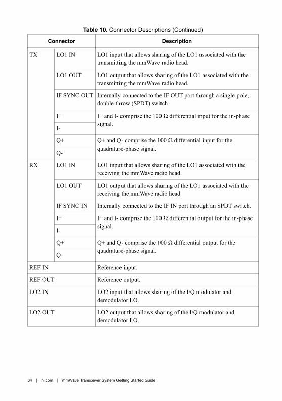
Table 10. Connector Descriptions (Continued)
Connector Description
TX LO1 IN LO1 input that allows sharing of the LO1 associated with thetransmitting the mmWave radio head.
LO1 OUT LO1 output that allows sharing of the LO1 associated with thetransmitting the mmWave radio head.
IF SYNC OUT Internally connected to the IF OUT port through a single-pole,double-throw (SPDT) switch.
I+ I+ and I- comprise the 100 Ω differential input for the in-phasesignal.
I-
Q+ Q+ and Q- comprise the 100 Ω differential input for thequadrature-phase signal.
Q-
RX LO1 IN LO1 input that allows sharing of the LO1 associated with thereceiving the mmWave radio head.
LO1 OUT LO1 output that allows sharing of the LO1 associated with thereceiving the mmWave radio head.
IF SYNC IN Internally connected to the IF IN port through an SPDT switch.
I+ I+ and I- comprise the 100 Ω differential output for the in-phasesignal.
I-
Q+ Q+ and Q- comprise the 100 Ω differential output for thequadrature-phase signal.
Q-
REF IN Reference input.
REF OUT Reference output.
LO2 IN LO2 input that allows sharing of the I/Q modulator anddemodulator LO.
LO2 OUT LO2 output that allows sharing of the I/Q modulator anddemodulator LO.
64 | ni.com | mmWave Transceiver System Getting Started Guide

PXIe-3630 Front Panel and LEDs
PXIe-3630I/Q Digitizer
REF IN
+10 dBmNOM
+13 dBmMAX
1.5 Vp-pDIFF MAX
1.5 Vp-pDIFF MAX
0 Vcm
ALL PORTS 50 Ω
REFOUT
0
1
2
3
Q+Q–
I+I–
ACCESS ACTIVE
Table 11. Connector Descriptions
Connector Description
0 Digital connector for the in-phase/quadrature (I/Q) data. Must be connected tothe PXIe-7902.
1 Digital connector for the I/Q data. Must be connected to the PXIe-7902.
2 Digital connector for the I/Q data. Must be connected to the PXIe-7902.
3 Digital connector for the I/Q data. Must be connected to the PXIe-7902.
REF OUT Output terminal for an external reference signal for the sampling clock of thedevice. REF OUT is an MMPX (f) connector with 96 MHz output. The outputis not always active and must first be configured.
mmWave Transceiver System Getting Started Guide | © National Instruments | 65

Table 11. Connector Descriptions (Continued)
Connector Description
REF IN Currently unsupported. Input terminal for an external reference signal for thesampling clock of the device. Use the PXI_100 backplane reference as areference input.
I+ Differential inputs for thein-phase signal.
Inputs are MMPX (f) connectors with 50 Ω outputimpedance. Both I+/- and Q+/- components presenta differential 100 Ω load with a common modevoltage of 0 V. For single-ended orientation, use thepositive input while providing 50 Ω termination tothe negative component. Differential operation isrecommended for best performance. Whenconnecting to the PXIe-3620, connect MMPX (m)-to-MMPX (m) cables to the corresponding TXconnectors.
I-
Q+ Differential inputs for thequadrature-phase signal.
Q-
Table 12. LED Indicators
LED Description Color State Indication
ACCESS Indicates if the ADC within themodule is powered.
OFF — The ADC is not powered.
Green Solid The ADC is powered andready for normaloperation.
ACTIVE Indicates the configuration statusof the module.
OFF — The ADC is not powered.
Yellow Blinking The module is beingconfigured.
Green Solid The ADC is operating.
66 | ni.com | mmWave Transceiver System Getting Started Guide
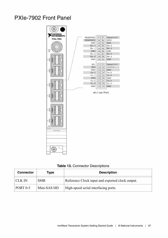
PXIe-7902 Front Panel
PXIe-7902
CLKIN
PO
RT
2P
OR
T4
PO
RT
5P
OR
T3
PO
RT
0P
OR
T1
RESERVED
RESERVED
GND
Rx+ 1
Rx– 1
GND
Rx+ 3
Rx– 3
GND
SCL
SDA
GND
Tx+ 1
Tx– 1
GND
Tx+ 3
Tx– 3
GND
Optical 3.3 V
GPIO
GND
Rx+ 0
Rx– 0
GND
Rx+ 2
Rx– 2
GND
Optical 3.3 V
EEPROM 3.3 V
GND
Tx+ 0
Tx– 0
GND
Tx+ 2
Tx– 2
GND
x6 (1 per Port)
A1
A2
A3A4
A5A6
A7A8
A9
B1
B2
B3B4
B5B6
B7B8
B9
C1
C2
C3C4
C5C6
C7C8
C9
D1
D2
D3D4
D5D6
D7D8
D9
Table 13. Connector Descriptions
Connector Type Description
CLK IN SMB Reference Clock input and exported clock output.
PORT 0-5 Mini-SAS HD High-speed serial interfacing ports.
mmWave Transceiver System Getting Started Guide | © National Instruments | 67

mmRH-3602 Front/Back Panel and LEDs
mmRH-3602 Front Panel
NI mmRH-360224.25–33.4 GHz Transceiver
TX Max Output Power+25 dBm
RX Input Damage LevelHigh Gain: -16 dBm
Low Gain: 0 dBm
TX1/RX1 RX2
50ΩCoupling Torque90 N-cm / 8 lbf-in
Table 14. mmRH-3602 Front Panel Connector Descriptions
Connector Description
TX1/RX1 Transmitter or receiver RF I/O, depending on the configuration.
RX2 Receiver input only. This port can be used to conduct receive measurementswhen the TX1/RX1 port is transmitting.
68 | ni.com | mmWave Transceiver System Getting Started Guide

mmRH-3602 Back Panel
LO IN RX
LO IN TX
IF OUT
IF IN
+12 dBm MAX
0 dBm MAX
DIO 1 DIO 0
ACTIVE ACCESS
50ΩCoupling Torque90 N-cm / 8 lbf-in
Input Damage LevelLO: +9 dBm
12 V 2.5A MAX
Table 15. mmRH-3602 Back Panel Connector Descriptions
Connector Description
LO IN TX LO input for the transmitter.
IF IN IF input for the transmitter.
LO IN RX LO input for the receiver.
IF OUT IF output for the receiver.
DIO 1 Digital I/O from the PXIe-3620 module to control the mmWave radio head.
DIO 0 Digital I/O from the PXIe-3620 module to control the mmWave radio head.
Power Power supply input.
Note The DIO 1 and DIO 0 ports cannot be used simultaneously.
mmWave Transceiver System Getting Started Guide | © National Instruments | 69
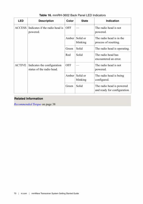
Table 16. mmRH-3602 Back Panel LED Indicators
LED Description Color State Indication
ACCESS Indicates if the radio head ispowered.
OFF — The radio head is notpowered.
Amber Solid orblinking
The radio head is in theprocess of resetting.
Green Solid The radio head is operating.
Red Solid The radio head hasencountered an error.
ACTIVE Indicates the configurationstatus of the radio head.
OFF — The radio head is notpowered.
Amber Solid orblinking
The radio head is beingconfigured.
Green Solid The radio head is poweredand ready for configuration.
Related Information
Recommended Torque on page 38
70 | ni.com | mmWave Transceiver System Getting Started Guide

mmRH-3603 Front/Back Panel and LEDs
mmRH-3603 Front Panel
NI mmRH-360337–43.5 GHz Transceiver
TX Max Output Power+25 dBm
RX Input Damage LevelHigh Gain: -16 dBm
Low Gain: 0 dBm
TX1/RX1 RX2
50ΩCoupling Torque90 N-cm / 8 lbf-in
Table 17. mmRH-3603 Front Panel Connector Descriptions
Connector Description
TX1/RX1 Transmitter or receiver RF I/O, depending on the configuration.
RX2 Receiver input only. This port can be used to conduct receive measurementswhen the TX1/RX1 port is transmitting.
mmWave Transceiver System Getting Started Guide | © National Instruments | 71
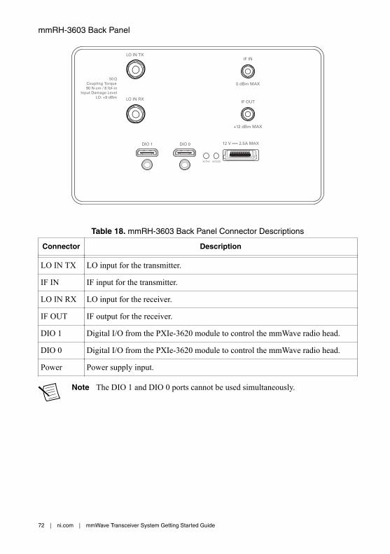
mmRH-3603 Back Panel
LO IN RX
LO IN TX
IF OUT
IF IN
+12 dBm MAX
0 dBm MAX
DIO 1 DIO 0
ACTIVE ACCESS
50ΩCoupling Torque90 N-cm / 8 lbf-in
Input Damage LevelLO: +9 dBm
12 V 2.5A MAX
Table 18. mmRH-3603 Back Panel Connector Descriptions
Connector Description
LO IN TX LO input for the transmitter.
IF IN IF input for the transmitter.
LO IN RX LO input for the receiver.
IF OUT IF output for the receiver.
DIO 1 Digital I/O from the PXIe-3620 module to control the mmWave radio head.
DIO 0 Digital I/O from the PXIe-3620 module to control the mmWave radio head.
Power Power supply input.
Note The DIO 1 and DIO 0 ports cannot be used simultaneously.
72 | ni.com | mmWave Transceiver System Getting Started Guide

Table 19. mmRH-3603 Back Panel LED Indicators
LED Description Color State Indication
ACCESS Indicates if the radio head ispowered.
OFF — The radio head is notpowered.
Amber Solid orblinking
The radio head is in theprocess of resetting.
Green Solid The radio head is operating.
Red Solid The radio head hasencountered an error.
ACTIVE Indicates the configurationstatus of the radio head.
OFF — The radio head is notpowered.
Amber Solid orblinking
The radio head is beingconfigured.
Green Solid The radio head is poweredand ready for configuration.
Related Information
Recommended Torque on page 38
mmWave Transceiver System Getting Started Guide | © National Instruments | 73

mmRH-3642 Front/Back Panel and LEDs
mmRH-3642 Front Panel
NI mmRH-364224.25–33.4 GHz TX Upconverter
TX Max Output Power+27 dBm
TX1
50ΩCoupling Torque90 N-cm / 8 lbf-in
Table 20. mmRH-3642 Front Panel Connector Descriptions
Connector Description
TX1 Transmitter output.
mmRH-3642 Back Panel
LO IN TXIF IN
0 dBm MAX
DIO 1 DIO 0
ACTIVE ACCESS
50ΩCoupling Torque90 N-cm / 8 lbf-in
Input Damage LevelLO: +9 dBm
12 V 2.5A MAX
74 | ni.com | mmWave Transceiver System Getting Started Guide

Table 21. mmRH-3642 Back Panel Connector Descriptions
Connector Description
LO IN TX LO input for the transmitter.
IF IN IF input for the transmitter.
DIO 1 Digital I/O from the PXIe-3620 module to control the mmWave radio head.
DIO 0 Digital I/O from the PXIe-3620 module to control the mmWave radio head.
Power Power supply input.
Note The DIO 1 and DIO 0 ports cannot be used simultaneously.
Table 22. mmRH-3642 Back Panel LED Indicators
LED Description Color State Indication
ACCESS Indicates if the radio head ispowered.
OFF — The radio head is notpowered.
Amber Solid orblinking
The radio head is in theprocess of resetting.
Green Solid The radio head is operating.
Red Solid The radio head hasencountered an error.
ACTIVE Indicates the configurationstatus of the radio head.
OFF — The radio head is notpowered.
Amber Solid orblinking
The radio head is beingconfigured.
Green Solid The radio head is poweredand ready for configuration.
Related Information
Recommended Torque on page 38
mmWave Transceiver System Getting Started Guide | © National Instruments | 75

mmRH-3643 Front/Back Panel and LEDs
mmRH-3643 Front Panel
NI mmRH-364337 –43.5 GHz TX Upconverter
TX Max Output Power+27 dBm
TX1
50ΩCoupling Torque90 N-cm / 8 lbf-in
Table 23. mmRH-3643 Front Panel Connector Descriptions
Connector Description
TX1 Transmitter output.
mmRH-3643 Back Panel
LO IN TXIF IN
0 dBm MAX
DIO 1 DIO 0
ACTIVE ACCESS
50ΩCoupling Torque90 N-cm / 8 lbf-in
Input Damage LevelLO: +9 dBm
12 V 2.5A MAX
76 | ni.com | mmWave Transceiver System Getting Started Guide

Table 24. mmRH-3643 Back Panel Connector Descriptions
Connector Description
LO IN TX LO input for the transmitter.
IF IN IF input for the transmitter.
DIO 1 Digital I/O from the PXIe-3620 module to control the mmWave radio head.
DIO 0 Digital I/O from the PXIe-3620 module to control the mmWave radio head.
Power Power supply input.
Note The DIO 1 and DIO 0 ports cannot be used simultaneously.
Table 25. mmRH-3643 Back Panel LED Indicators
LED Description Color State Indication
ACCESS Indicates if the radio head ispowered.
OFF — The radio head is notpowered.
Amber Solid orblinking
The radio head is in theprocess of resetting.
Green Solid The radio head is operating.
Red Solid The radio head hasencountered an error.
ACTIVE Indicates the configurationstatus of the radio head.
OFF — The radio head is notpowered.
Amber Solid orblinking
The radio head is beingconfigured.
Green Solid The radio head is poweredand ready for configuration.
Related Information
Recommended Torque on page 38
mmWave Transceiver System Getting Started Guide | © National Instruments | 77

mmRH-3647 Front/Back Panel and LEDs
mmRH-3647 Front Panel
Max Output Power+26 dBm
WR-12 Waveguide5.0lbf-in Torque
mmRH-364771– 76 GHz TX Upconverter
Table 26. mmRH-3647 Front Panel Connector Descriptions
Connector Description
RF OUT Transmitter RF output.
mmRH-3647 Back Panel
CONTROLLO IN
ACCESS
Input Damage Levels:LO: +12 dBmIF: –20 dBm
IF IN
ACTIVE
2A MAX12 V
Table 27. mmRH-3647 Back Panel Connector Descriptions
Connector Description
LO IN LO input for the transmitter.
IF IN IF input for the transmitter.
78 | ni.com | mmWave Transceiver System Getting Started Guide
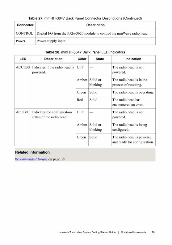
Table 27. mmRH-3647 Back Panel Connector Descriptions (Continued)
Connector Description
CONTROL Digital I/O from the PXIe-3620 module to control the mmWave radio head.
Power Power supply input.
Table 28. mmRH-3647 Back Panel LED Indicators
LED Description Color State Indication
ACCESS Indicates if the radio head ispowered.
OFF — The radio head is notpowered.
Amber Solid orblinking
The radio head is in theprocess of resetting.
Green Solid The radio head is operating.
Red Solid The radio head hasencountered an error.
ACTIVE Indicates the configurationstatus of the radio head.
OFF — The radio head is notpowered.
Amber Solid orblinking
The radio head is beingconfigured.
Green Solid The radio head is poweredand ready for configuration.
Related Information
Recommended Torque on page 38
mmWave Transceiver System Getting Started Guide | © National Instruments | 79

mmRH-3652 Front/Back Panel and LEDs
mmRH-3652 Front Panel
NI mmRH-365224.25–33.4 GHz RX Downconverter
RX Input Damage LevelHigh Gain: -16 dBm
Low Gain: -1 dBm
RX1
50ΩCoupling Torque90 N-cm / 8 lbf-in
Table 29. mmRH-3652 Front Panel Connector Descriptions
Connector Description
RX1 Receiver RF input.
mmRH-3652 Back Panel
LO IN RXIF OUT
+12 dBm MAX
DIO 1 DIO 0
ACTIVE ACCESS
50ΩCoupling Torque90 N-cm / 8 lbf-in
Input Damage LevelLO: +9 dBm
12 V 2.5A MAX
80 | ni.com | mmWave Transceiver System Getting Started Guide

Table 30. mmRH-3652 Back Panel Connector Descriptions
Connector Description
LO IN RX LO input for the receiver.
IF OUT IF output for the receiver.
DIO 1 Digital I/O from the PXIe-3620 module to control the mmWave radio head.
DIO 0 Digital I/O from the PXIe-3620 module to control the mmWave radio head.
Power Power supply input.
Note The DIO 1 and DIO 0 ports cannot be used simultaneously.
Table 31. mmRH-3652 Back Panel LED Indicators
LED Description Color State Indication
ACCESS Indicates if the radio head ispowered.
OFF — The radio head is notpowered.
Amber Solid orblinking
The radio head is in theprocess of resetting.
Green Solid The radio head is operating.
Red Solid The radio head hasencountered an error.
ACTIVE Indicates the configurationstatus of the radio head.
OFF — The radio head is notpowered.
Amber Solid orblinking
The radio head is beingconfigured.
Green Solid The radio head is poweredand ready for configuration.
Related Information
Recommended Torque on page 38
mmWave Transceiver System Getting Started Guide | © National Instruments | 81

mmRH-3653 Front/Back Panel and LEDs
mmRH-3653 Front Panel
NI mmRH-365337–43.5 GHz RX Downconverter
RX Input Damage LevelHigh Gain: -16 dBm
Low Gain: -1 dBm
RX1
50ΩCoupling Torque90 N-cm / 8 lbf-in
Table 32. mmRH-3653 Front Panel Connector Descriptions
Connector Description
RX1 Receiver RF input.
mmRH-3653 Back Panel
LO IN RXIF OUT
+12 dBm MAX
DIO 1 DIO 0
ACTIVE ACCESS
50ΩCoupling Torque90 N-cm / 8 lbf-in
Input Damage LevelLO: +9 dBm
12 V 2.5A MAX
82 | ni.com | mmWave Transceiver System Getting Started Guide

Table 33. mmRH-3653 Back Panel Connector Descriptions
Connector Description
LO IN RX LO input for the receiver.
IF OUT IF output for the receiver.
DIO 1 Digital I/O from the PXIe-3620 module to control the mmWave radio head.
DIO 0 Digital I/O from the PXIe-3620 module to control the mmWave radio head.
Power Power supply input.
Note The DIO 1 and DIO 0 ports cannot be used simultaneously.
Table 34. mmRH-3653 Back Panel LED Indicators
LED Description Color State Indication
ACCESS Indicates if the radio head ispowered.
OFF — The radio head is notpowered.
Amber Solid orblinking
The radio head is in theprocess of resetting.
Green Solid The radio head is operating.
Red Solid The radio head hasencountered an error.
ACTIVE Indicates the configurationstatus of the radio head.
OFF — The radio head is notpowered.
Amber Solid orblinking
The radio head is beingconfigured.
Green Solid The radio head is poweredand ready for configuration.
Related Information
Recommended Torque on page 38
mmWave Transceiver System Getting Started Guide | © National Instruments | 83

mmRH-3657 Front/Back Panel and LEDs
mmRH-3657 Front Panel
WR-12 Waveguide5.0lbf-in Torque
mmRH-365771–76 GHz RX Downconverter
Input Damage Levels:High Gain: –37 dBmMid Gains: Consult ManualLow Gain: –7 dBm
Table 35. mmRH-3657 Front Panel Connector Descriptions
Connector Description
RF IN Receiver RF input.
mmRH-3657 Back Panel
CONTROLLO IN
ACCESS
Input Damage Levels:LO: +12 dBm
IF OUT
ACTIVE
2A MAX12 V
Table 36. mmRH-3657 Back Panel Connector Descriptions
Connector Description
LO IN LO input for receiver.
IF OUT IF output for receiver.
84 | ni.com | mmWave Transceiver System Getting Started Guide

Table 36. mmRH-3657 Back Panel Connector Descriptions (Continued)
Connector Description
CONTROL Digital I/O from the PXIe-3620 module to control the mmWave radio head.
Power Power supply input.
Table 37. mmRH-3657 Back Panel LED Indicators
LED Description Color State Indication
ACCESS Indicates if the radio head ispowered.
OFF — The radio head is notpowered.
Amber Solid orblinking
The radio head is in theprocess of resetting.
Green Solid The radio head is operating.
Red Solid The radio head hasencountered an error.
ACTIVE Indicates the configurationstatus of the radio head.
OFF — The radio head is notpowered.
Amber Solid orblinking
The radio head is beingconfigured.
Green Solid The radio head is poweredand ready for configuration.
Related Information
Recommended Torque on page 38
Where to Go NextRefer to the following figure for information about other product tasks and associatedresources for those tasks.
mmWave Transceiver System Getting Started Guide | © National Instruments | 85

EXPLORE LEARN CREATE
DISCOVER
Located online at ni.com/manuals
the application developmentenvironment (ADE)
for your application.
about the capabilities ofyour hardware with device
specifications.
custom applications withan application programming
interface (API).
more about your products through ni.com.
Servicesni.com/services
Supportni.com/support
Updatesni.com/updates
Getting Started withLabVIEW
NI-mmWave mmWave Transceiver System Specifications
Information is subject to change without notice. Refer to the NI Trademarks and Logo Guidelines at ni.com/trademarks forinformation on NI trademarks. Other product and company names mentioned herein are trademarks or trade names of theirrespective companies. For patents covering NI products/technology, refer to the appropriate location: Help»Patents in yoursoftware, the patents.txt file on your media, or the National Instruments Patent Notice at ni.com/patents. You can findinformation about end-user license agreements (EULAs) and third-party legal notices in the readme file for your NI product. Referto the Export Compliance Information at ni.com/legal/export-compliance for the NI global trade compliance policy and howto obtain relevant HTS codes, ECCNs, and other import/export data. NI MAKES NO EXPRESS OR IMPLIED WARRANTIES ASTO THE ACCURACY OF THE INFORMATION CONTAINED HEREIN AND SHALL NOT BE LIABLE FOR ANY ERRORS. U.S.Government Customers: The data contained in this manual was developed at private expense and is subject to the applicablelimited rights and restricted data rights as set forth in FAR 52.227-14, DFAR 252.227-7014, and DFAR 252.227-7015.
© 2017—2018 National Instruments. All rights reserved.
376531C-01 September 17, 2018