Embed Size (px)
Citation preview
5G-Sadri
mmWave Passive Reflectors
Ali Sadri, PhDSr. Director mmWave Standards and Advanced TechnologyIntel Corporation
June 2017
5G-<LastName>
Outline
• Motivation• Network Capacity and 5G• Relevance of mmWave Frequency Bands• mmWave System Design Challenges• Modular Antenna Array Architecture (MAA)• HW Architecture from POC to Product• Passive Gain Enhancement Techniques
2
5G-<LastName> 33
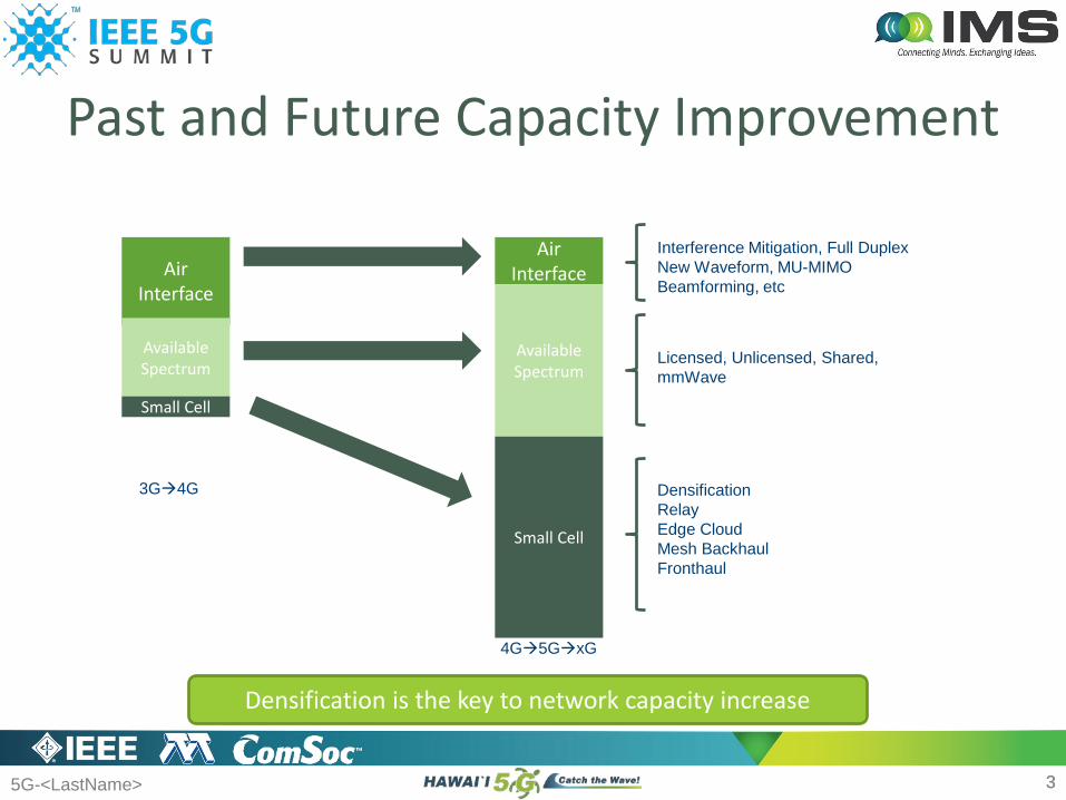
Past and Future Capacity Improvement
Air Interface
Available Spectrum
Small Cell
Air Interface
Available Spectrum
Small Cell
Interference Mitigation, Full DuplexNew Waveform, MU-MIMOBeamforming, etc
Licensed, Unlicensed, Shared,mmWave
DensificationRelayEdge CloudMesh BackhaulFronthaul
3G4G
4G5GxG
Densification is the key to network capacity increase
5G-<LastName>
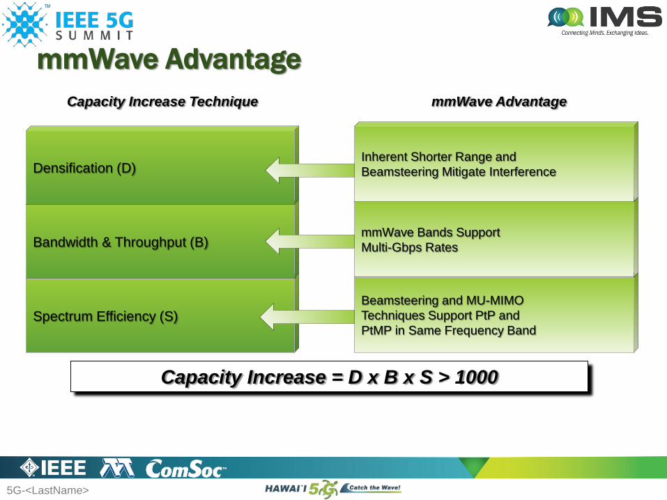
mmWave Advantage
Spectrum Efficiency (S)
Bandwidth & Throughput (B)
Densification (D)
Capacity Increase = D x B x S > 1000
Capacity Increase Technique mmWave Advantage
Beamsteering and MU-MIMO Techniques Support PtP and PtMP in Same Frequency Band
mmWave Bands Support Multi-Gbps Rates
Inherent Shorter Range and Beamsteering Mitigate Interference
5G-<LastName> 5
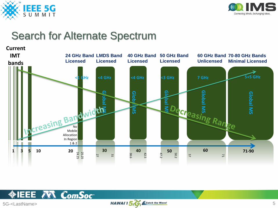
Search for Alternate Spectrum
5 10 20 30 40 50 71-90
NoMobile
AllocationIn Region
1 & 2
<1 GHz <4 GHz <4 GHz 7 GHzG
lobal MS
<3 GHz
Global M
S
Global M
S
Global M
S
24.2525.25
27 31
38.6
42.5
47.2
50.2
57 71
5+5 GHz
Global M
S
60 GHz BandUnlicensed
40 GHz BandLicensed
LMDS BandLicensed
24 GHz BandLicensed
50 GHz BandLicensed
70-80 GHz BandsMinimal Licensed
3
CurrentIMT
bands
1 60
5G-<LastName> 66
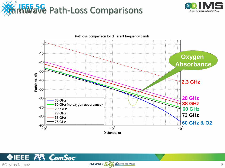
mmWave Path-Loss Comparisons
2.3 GHz
28 GHz38 GHz60 GHz
Oxygen Absorbance
73 GHz60 GHz & O2

5G-<LastName> 7
eNB
7
Centralized Backhaul Network Concept
eNBeNB
mCSC
mCSCmCSC
mCSC
mCSC
mCSC
5G-<LastName> 88
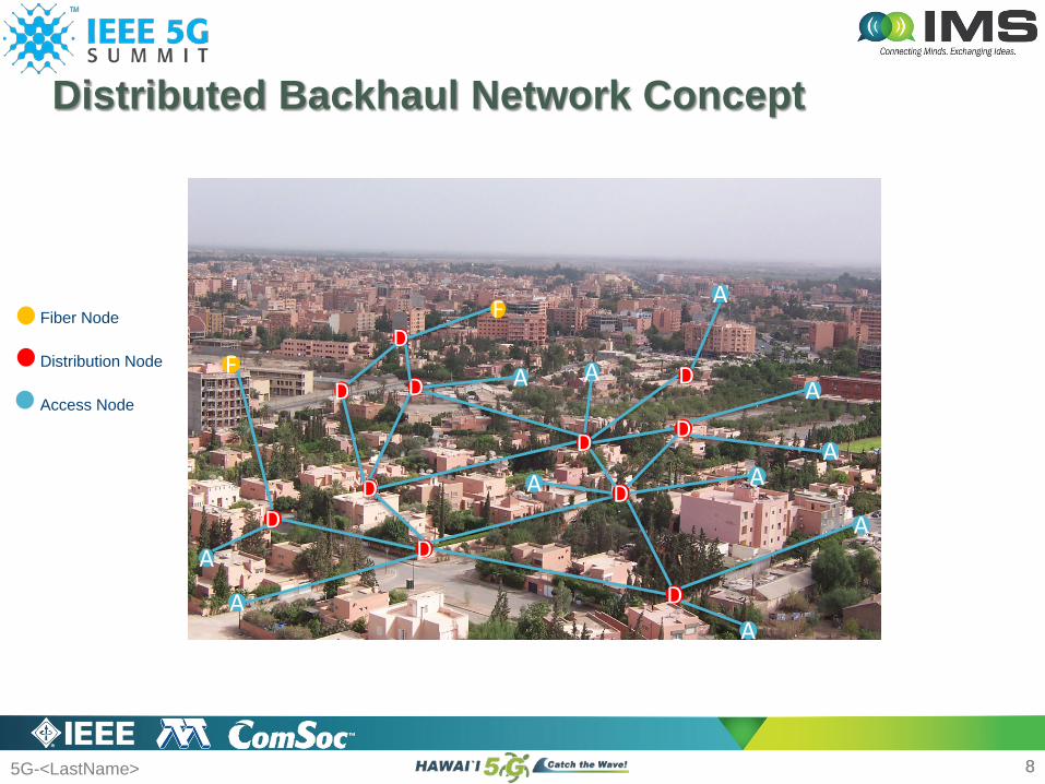
Fiber Node
Distribution Node
Access Node
DD
A
F
A
D
DA
A
A
DA
D
DA
D
D A
A
DF
A
Distributed Backhaul Network Concept
D
A
5G-<LastName> 9
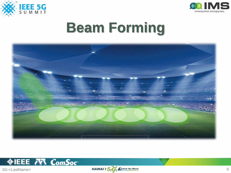
Beam Forming

5G-<LastName> 1010
Challenges in RF & Antenna• Feed line loss: (8-by-8) elements
Antenna spacing: λ2
= 𝑐𝑐/𝑓𝑓2
= 5𝑚𝑚𝑚𝑚2
= 2.5mm
60 GHz
Antenna spacing: λ2
= 𝑐𝑐/𝑓𝑓2
= 7.69𝑚𝑚𝑚𝑚2
@ 28 GHz is 5.36mm and @ 39 GHz is 3.85mm
From 60 GHz to 28 GHz (or 38 GHz),• The required area getting bigger then feed line getting longer (roughly double).• Feed loss is also a function of frequency (higher loss at 60 GHz)
28 or 39 GHz
5G-<LastName> 11
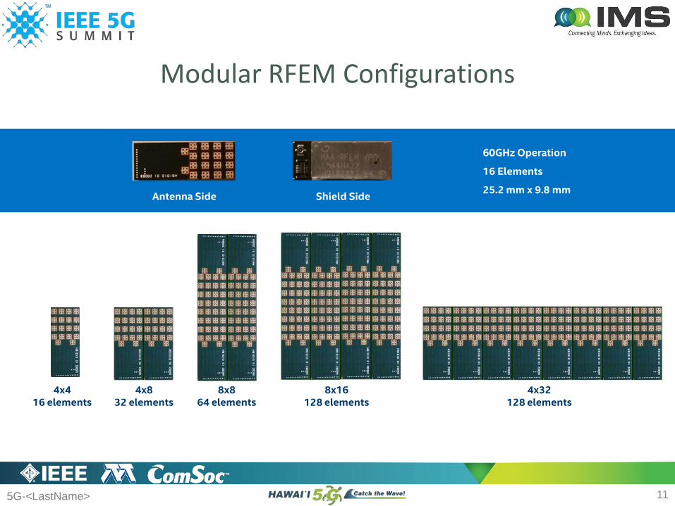
Modular RFEM Configurations
Antenna Side Shield Side
60GHz Operation
16 Elements
25.2 mm x 9.8 mm
8x864 elements
8x16128 elements
4x832 elements
4x416 elements
4x32128 elements
5G-<LastName>
24
27
30
33
36
39
42
45
48
0 1 2 3 4 5 6 7 8 9
EIRP
(dBm
)
RFIC Count (16 elements per RFIC)
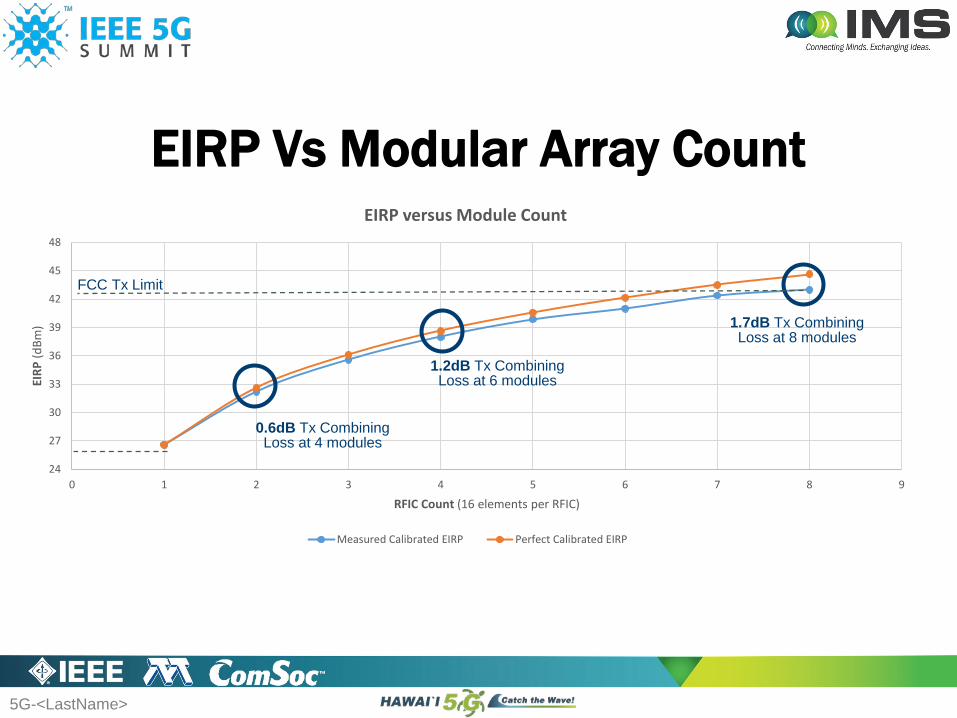
EIRP versus Module Count
Measured Calibrated EIRP Perfect Calibrated EIRP
EIRP Vs Modular Array Count
0.6dB Tx CombiningLoss at 4 modules
1.2dB Tx CombiningLoss at 6 modules
1.7dB Tx CombiningLoss at 8 modules
FCC Tx Limit
Intel Confidential 12
5G-<LastName> 1313
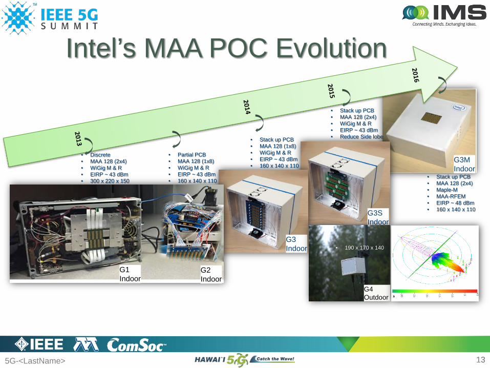
Intel’s MAA POC Evolution
G3SIndoor
G3Indoor
G3MIndoor
G1Indoor
G2Indoor
• Discrete• MAA 128 (2x4)• WiGig M & R• EIRP ~ 43 dBm• 300 x 220 x 150
• Partial PCB• MAA 128 (1x8)• WiGig M & R• EIRP ~ 43 dBm• 160 x 140 x 110
• Stack up PCB• MAA 128 (1x8)• WiGig M & R• EIRP ~ 43 dBm• 160 x 140 x 110
• Stack up PCB• MAA 128 (2x4)• WiGig M & R• EIRP ~ 43 dBm• Reduce Side lobe
• Stack up PCB• MAA 128 (2x4)• Maple-M • MAA-RFEM• EIRP ~ 48 dBm• 160 x 140 x 110
G4Outdoor
• 190 x 170 x 140
5G-<LastName> 14
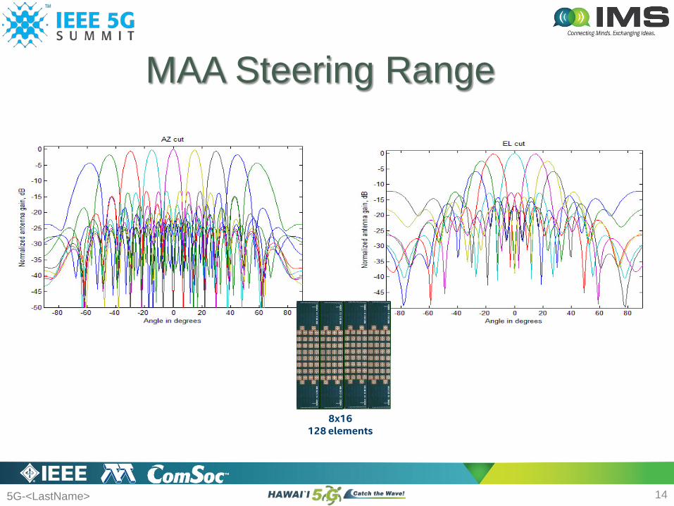
MAA Steering Range
8x16128 elements

5G-<LastName>
• Hardware Overview• Indoor Design
• Easy access to ports• Easy signal breakout for chamber tests• Easy tabletop, tripod, post, ceiling
installation• Antenna Array
• 128 elements - 8x16 array - balanced feeds
• 8x RFEMs based on Intel WiGig product• 1x Intel WiGig Baseband Modem Module
G5 Evaluation Kit
15Intel Confidential
5G-<LastName>
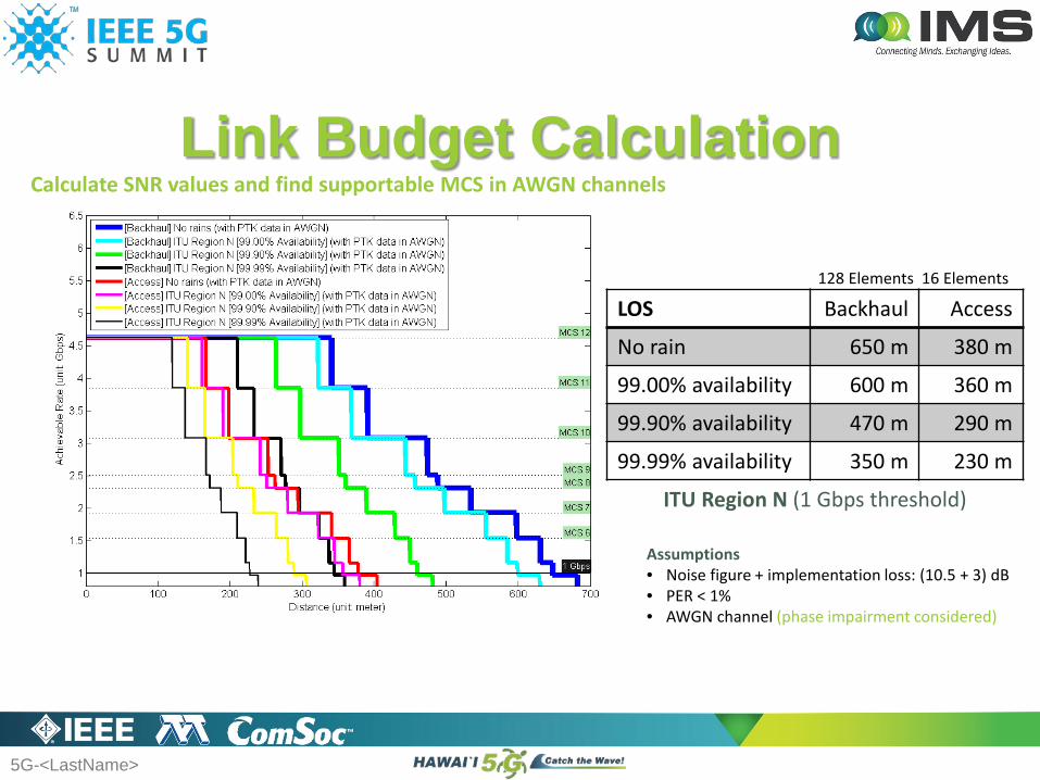
Link Budget Calculation
ITU Region N (1 Gbps threshold)
Assumptions• Noise figure + implementation loss: (10.5 + 3) dB• PER < 1%• AWGN channel (phase impairment considered)
Calculate SNR values and find supportable MCS in AWGN channels
LOS Backhaul Access
No rain 650 m 380 m
99.00% availability 600 m 360 m
99.90% availability 470 m 290 m
99.99% availability 350 m 230 m
128 Elements 16 Elements
5G-<LastName>
Passive Gain Enhancement for Active RFEM
Ali Sadri, PhDIntel Corporation
Cheng-Yuan Chin, PhDWhayu Industrial Co., Ltd.
5G-<LastName>
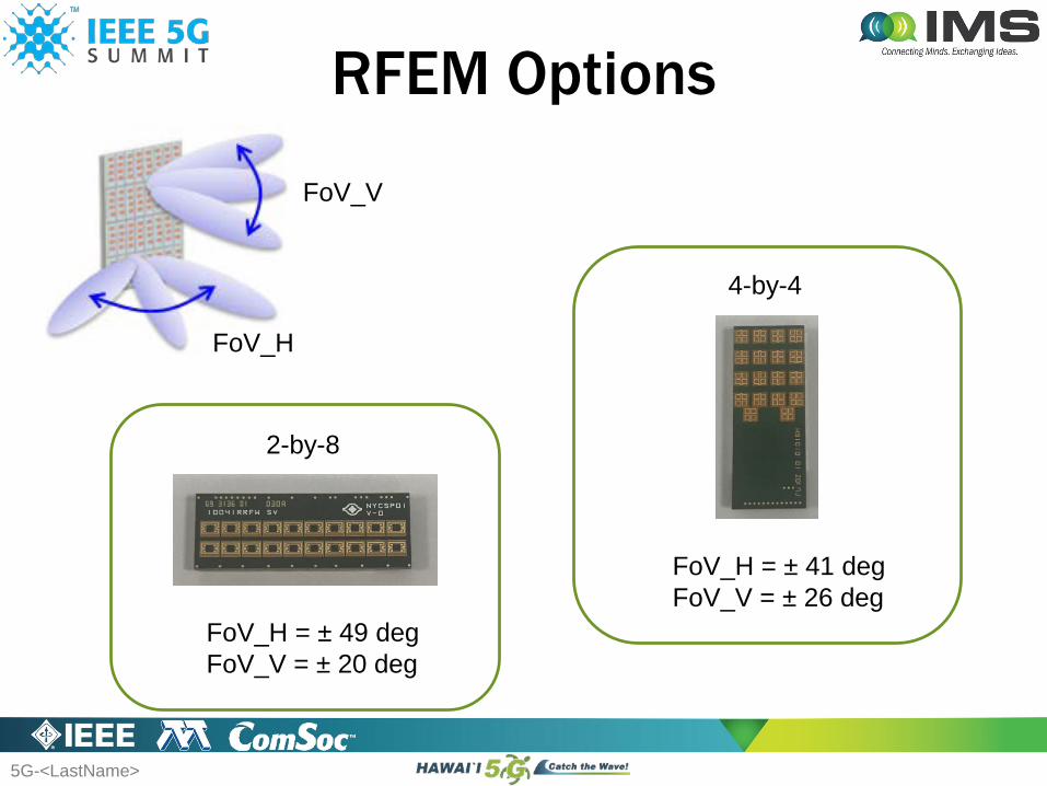
RFEM Options
2-by-8
FoV_H = ± 49 degFoV_V = ± 20 deg
4-by-4
FoV_H = ± 41 degFoV_V = ± 26 deg
FoV_V
FoV_H
5G-<LastName>
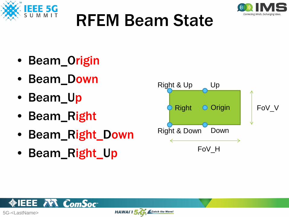
RFEM Beam State
• Beam_Origin• Beam_Down• Beam_Up• Beam_Right• Beam_Right_Down• Beam_Right_Up
FoV_V
FoV_H
Origin
Up
Down
Right
Right & Down
Right & Up
5G-<LastName>
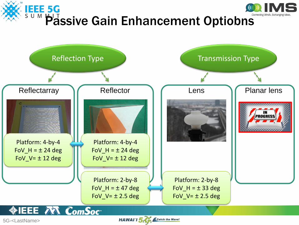
Passive Gain Enhancement Optiobns
Reflection Type Transmission Type
ReflectorReflectarray Lens Planar lens
Platform: 2-by-8FoV_H = ± 47 degFoV_V= ± 2.5 deg
Platform: 2-by-8FoV_H = ± 33 degFoV_V= ± 2.5 deg
Platform: 4-by-4FoV_H = ± 24 degFoV_V= ± 12 deg
Platform: 4-by-4FoV_H = ± 24 degFoV_V= ± 12 deg
5G-<LastName>
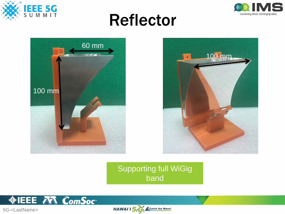
Reflector
Supporting full WiGigband
(57-71 GHz)
60 mm
100 mm
100 mm

5G-<LastName>
Beam_O
Beam_O
Feeding pattern
Total pattern

5G-<LastName>
Beam_D
Beam_D
Feeding pattern
Total pattern
5G-<LastName>
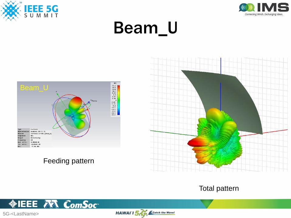
Beam_U
Beam_U
Feeding pattern
Total pattern
5G-<LastName>
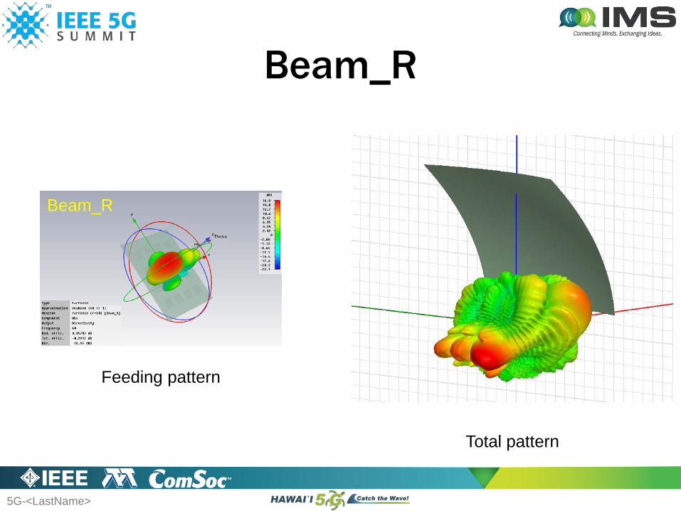
Beam_R
Beam_R
Feeding pattern
Total pattern
5G-<LastName>
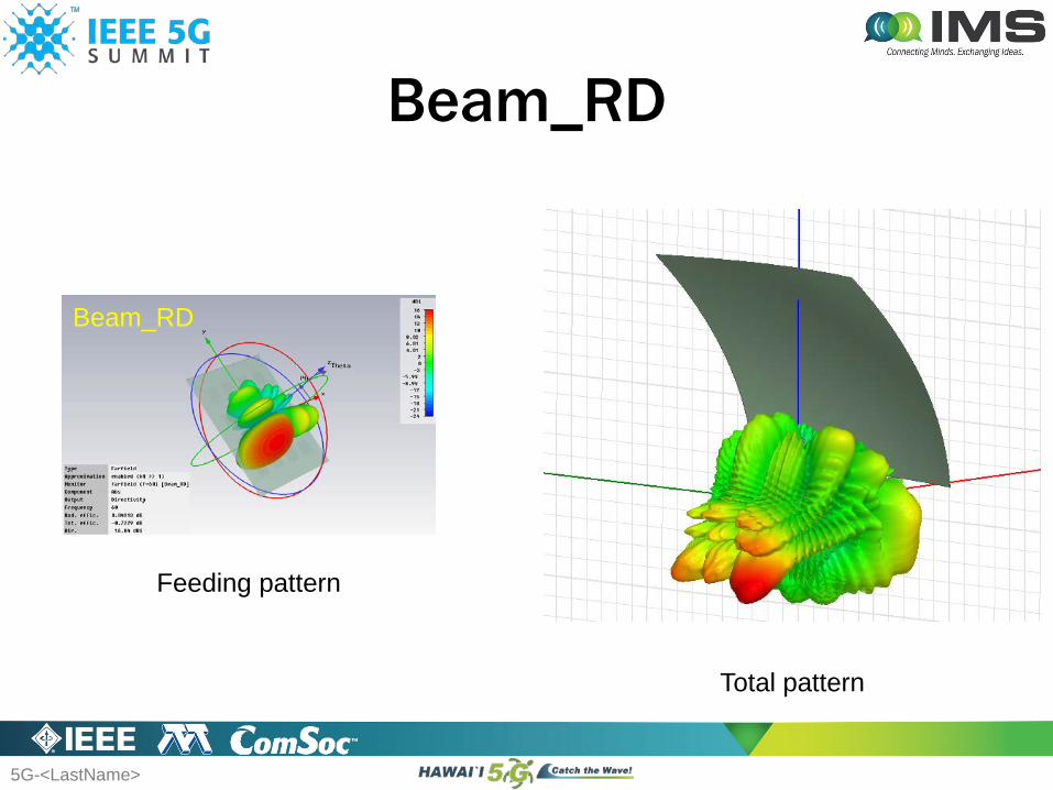
Beam_RD
Beam_RD
Feeding pattern
Total pattern
5G-<LastName>
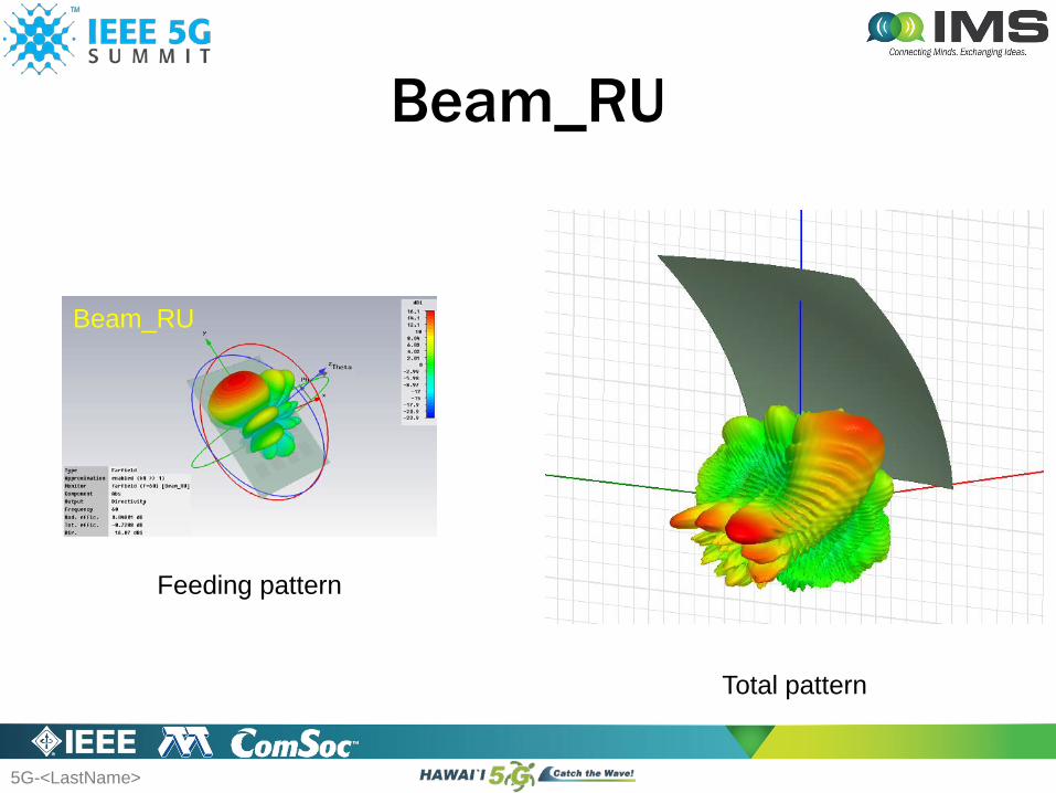
Beam_RU
Beam_RU
Feeding pattern
Total pattern
5G-<LastName>
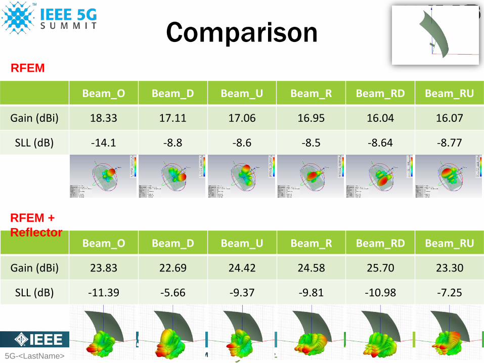
Comparison
Beam_O Beam_D Beam_U Beam_R Beam_RD Beam_RU
Gain (dBi) 18.33 17.11 17.06 16.95 16.04 16.07
SLL (dB) -14.1 -8.8 -8.6 -8.5 -8.64 -8.77
RFEM
Beam_O Beam_D Beam_U Beam_R Beam_RD Beam_RU
Gain (dBi) 23.83 22.69 24.42 24.58 25.70 23.30
SLL (dB) -11.39 -5.66 -9.37 -9.81 -10.98 -7.25
RFEM + Reflector
5G-<LastName>
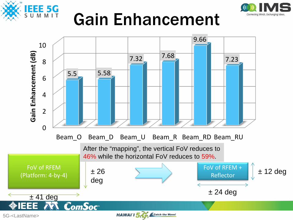
Gain Enhancement
0
2
4
6
8
10
Beam_O Beam_D Beam_U Beam_R Beam_RD Beam_RU
5.5 5.58
7.32 7.68
9.66
7.23
Gai
n En
hanc
emen
t (dB
)
FoV of RFEM(Platform: 4-by-4) ± 26
deg
± 41 deg
FoV of RFEM + Reflector
± 24 deg
± 12 deg
After the “mapping”, the vertical FoV reduces to 46% while the horizontal FoV reduces to 59%.
5G-<LastName>
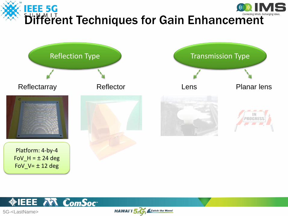
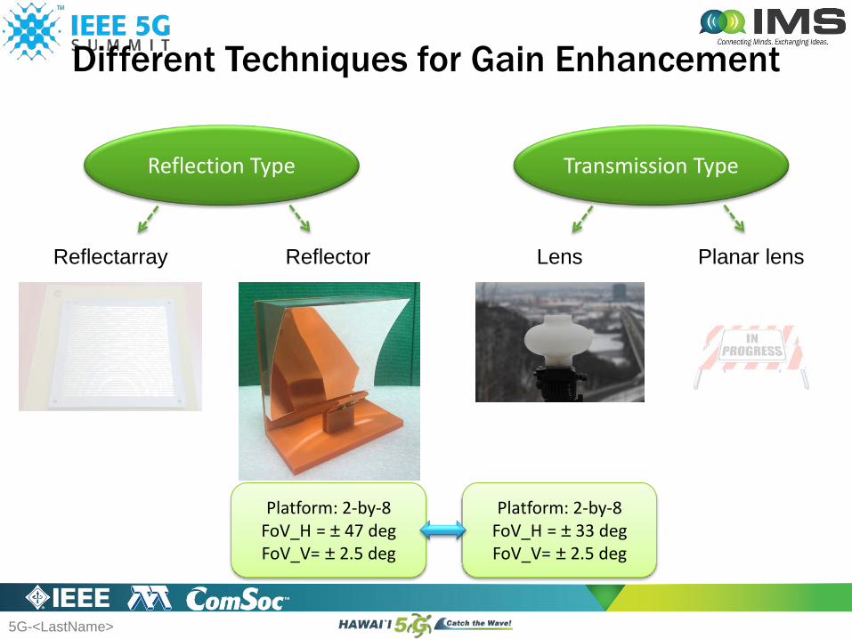
Different Techniques for Gain Enhancement
Reflection Type Transmission Type
ReflectorReflectarray Lens Planar lens
Platform: 4-by-4FoV_H = ± 24 degFoV_V= ± 12 deg
5G-<LastName>
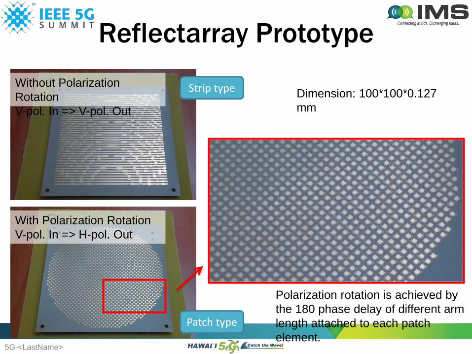
Reflectarray PrototypeWithout Polarization RotationV-pol. In => V-pol. Out
With Polarization RotationV-pol. In => H-pol. Out
Patch type
Strip type
Polarization rotation is achieved by the 180 phase delay of different arm length attached to each patch element.
Dimension: 100*100*0.127 mm
5G-<LastName>
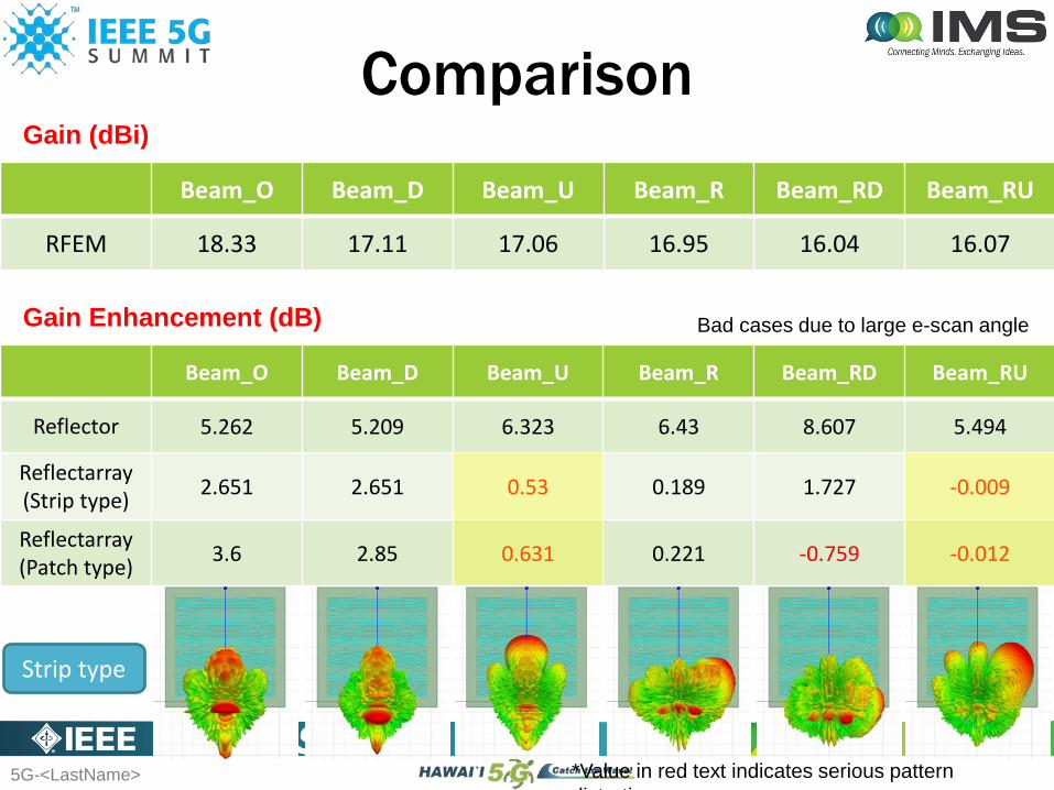
Comparison
Beam_O Beam_D Beam_U Beam_R Beam_RD Beam_RU
RFEM 18.33 17.11 17.06 16.95 16.04 16.07
Beam_O Beam_D Beam_U Beam_R Beam_RD Beam_RU
Reflector 5.262 5.209 6.323 6.43 8.607 5.494
Reflectarray(Strip type) 2.651 2.651 0.53 0.189 1.727 -0.009
Reflectarray(Patch type) 3.6 2.85 0.631 0.221 -0.759 -0.012
Gain (dBi)
Gain Enhancement (dB)
*Value in red text indicates serious pattern di t ti
Strip type
Bad cases due to large e-scan angle
5G-<LastName>
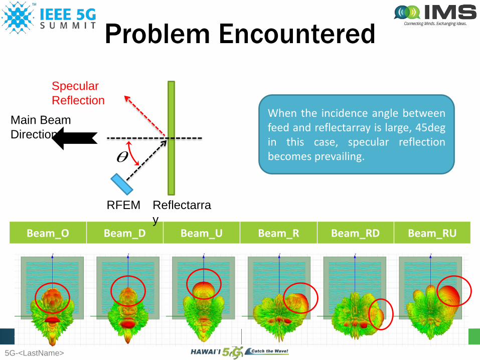
Problem Encountered
Beam_O Beam_D Beam_U Beam_R Beam_RD Beam_RU
θ
RFEM Reflectarray
Main Beam Direction
Specular Reflection
When the incidence angle betweenfeed and reflectarray is large, 45degin this case, specular reflectionbecomes prevailing.
5G-<LastName>
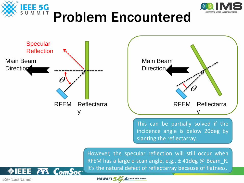
Problem Encountered
θ
RFEM Reflectarray
Specular Reflection
Main Beam Direction
θ
RFEM Reflectarray
Main Beam Direction
This can be partially solved if theincidence angle is below 20deg byslanting the reflectarray.
However, the specular reflection will still occur whenRFEM has a large e-scan angle, e.g., ± 41deg @ Beam_R.It’s the natural defect of reflectarray because of flatness.

5G-<LastName>
Comparison Table
Reflectarray Reflector
Weight Light Heavy
Gain Enhancement Inferior to reflector due to dielectric loss Good
Bandwidth
Narrow BW for single layer, lower costWide BW for multi layer, higher cost
Wide
Degree of Difficulty for Production Yield concern Normal
Limitation Cannot support large steering angle N/A
5G-<LastName>
Different Techniques for Gain Enhancement
Reflection Type Transmission Type
ReflectorReflectarray Lens Planar lens
Platform: 2-by-8FoV_H = ± 47 degFoV_V= ± 2.5 deg
Platform: 2-by-8FoV_H = ± 33 degFoV_V= ± 2.5 deg
5G-<LastName>
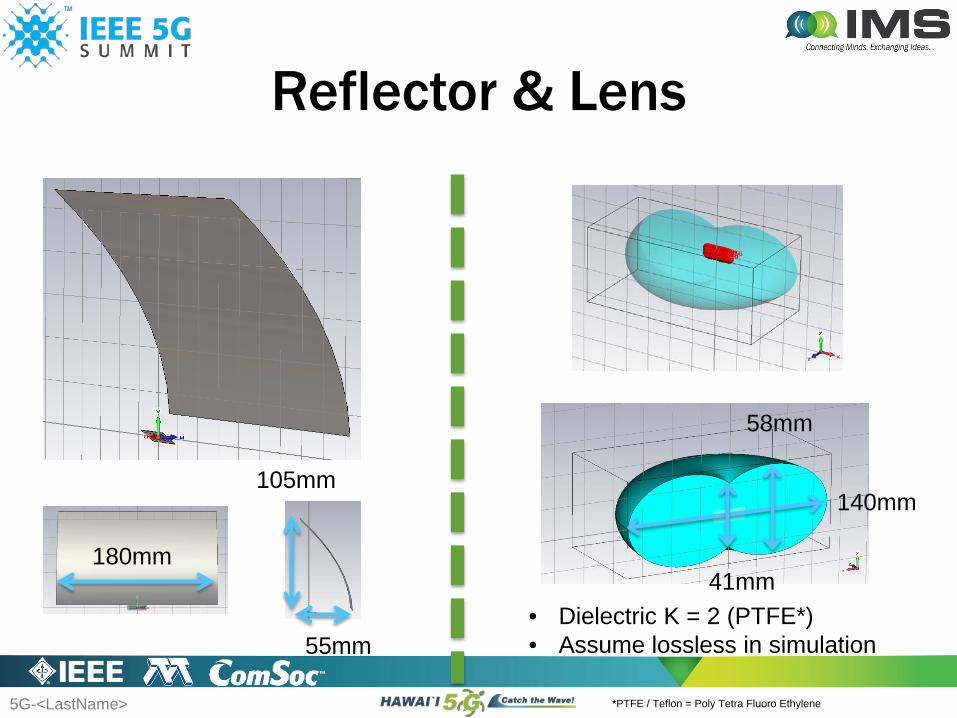
Reflector & Lens
140mm
41mm
58mm
180mm
105mm
55mm• Dielectric K = 2 (PTFE*)• Assume lossless in simulation
*PTFE / Teflon = Poly Tetra Fluoro Ethylene
5G-<LastName>
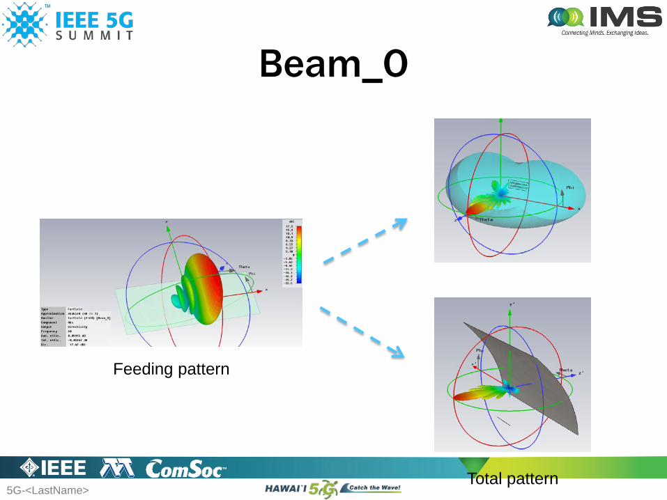
Beam_O
Feeding pattern
Total pattern
5G-<LastName>
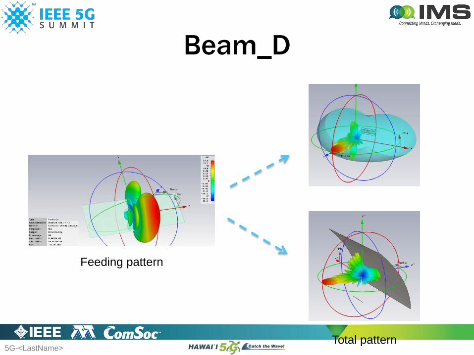
Beam_D
Feeding pattern
Total pattern

5G-<LastName>
Beam_U
Feeding pattern
Total pattern
5G-<LastName>
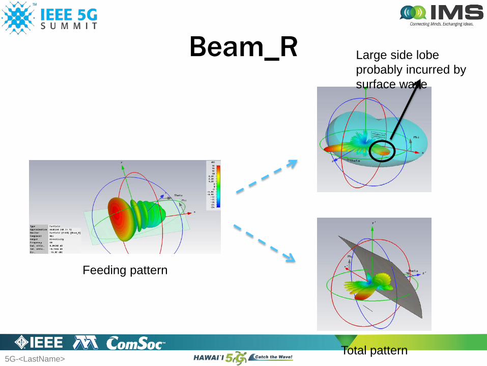
Beam_R Large side lobe probably incurred by surface wave
Feeding pattern
Total pattern
5G-<LastName>
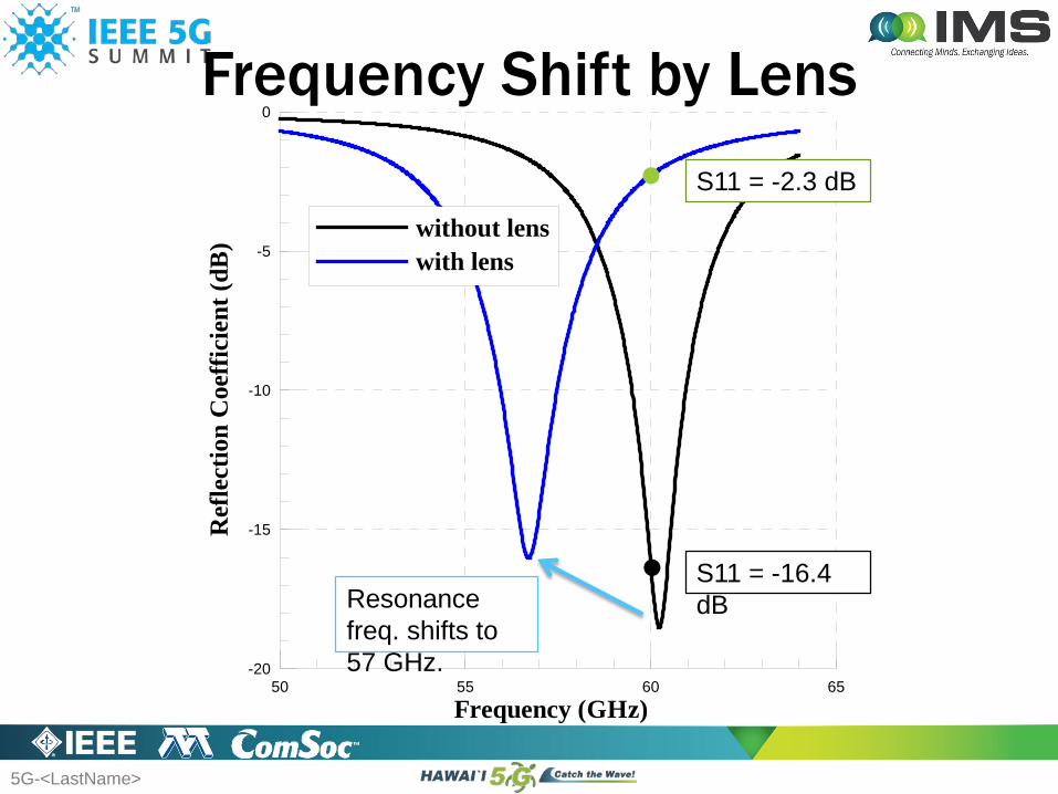
Frequency Shift by Lens
50 55 60 65Frequency (GHz)
-20
-15
-10
-5
0
Ref
lect
ion
Coe
ffic
ient
(dB
) without lenswith lens
Resonance freq. shifts to 57 GHz.
S11 = -16.4 dB
S11 = -2.3 dB

5G-<LastName>
Beam_O Beam_D Beam_U Beam_R
Directivity (dBi) 27.9 26.0 26.0 25.7
SLL (dB) -12.6 -9.8 -9.8 -10.4 (-5.6)
RFEM + Lens
FoV_V = ± 2.5 degFoV_H = ± 33 deg
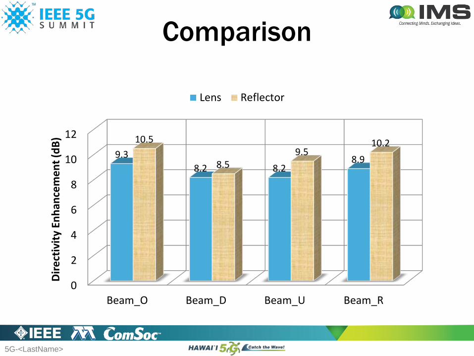
Comparison
Beam_O Beam_D Beam_U Beam_R
Directivity (dBi) 29.7 26.3 27.3 27.0
SLL (dB) -13.2 -12.8 -13.7 -9.2
RFEM + Reflector
FoV_V = ± 2.5 degFoV_H = ± 47 deg
-10.4 for fist sidelobewhile -5.6 for the max. one
5G-<LastName>
0
2
4
6
8
10
12
Beam_O Beam_D Beam_U Beam_R
9.38.2 8.2
8.9
10.5
8.59.5
10.2
Dire
ctiv
ity E
nhan
cem
ent (
dB)
Lens Reflector
Comparison
5G-<LastName>
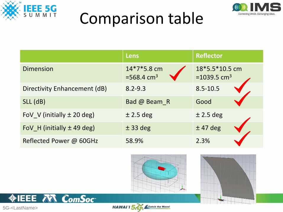
Lens Reflector
Dimension 14*7*5.8 cm=568.4 cm3
18*5.5*10.5 cm=1039.5 cm3
Directivity Enhancement (dB) 8.2-9.3 8.5-10.5
SLL (dB) Bad @ Beam_R Good
FoV_V (initially ± 20 deg) ± 2.5 deg ± 2.5 deg
FoV_H (initially ± 49 deg) ± 33 deg ± 47 deg
Reflected Power @ 60GHz 58.9% 2.3%
Comparison table
5G-<LastName> 4646
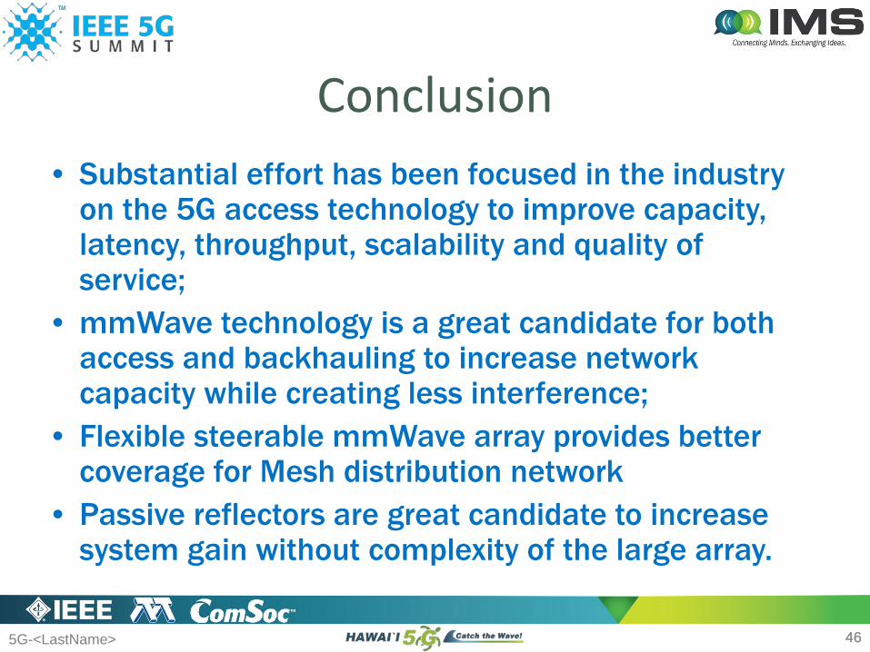
Conclusion• Substantial effort has been focused in the industry
on the 5G access technology to improve capacity, latency, throughput, scalability and quality of service;
• mmWave technology is a great candidate for both access and backhauling to increase network capacity while creating less interference;
• Flexible steerable mmWave array provides better coverage for Mesh distribution network
• Passive reflectors are great candidate to increase system gain without complexity of the large array.
5G-<LastName>
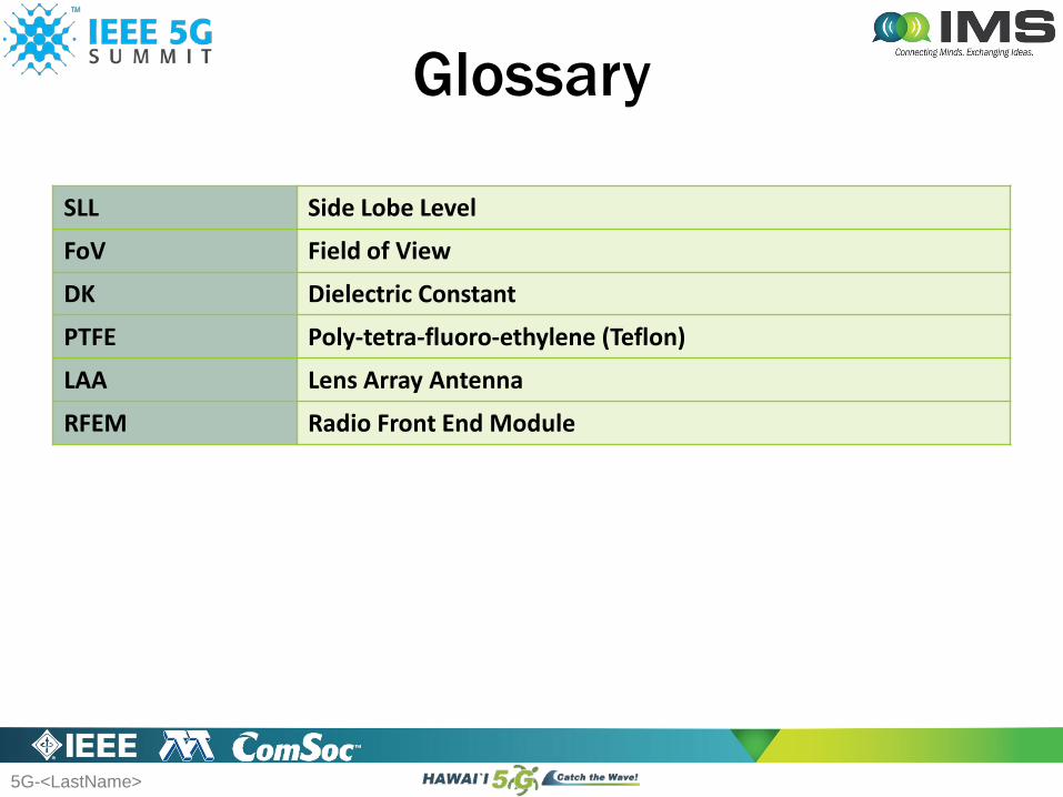
Glossary
SLL Side Lobe Level
FoV Field of View
DK Dielectric Constant
PTFE Poly-tetra-fluoro-ethylene (Teflon)
LAA Lens Array Antenna
RFEM Radio Front End Module

Intel Confidential — Do Not Forward