Embed Size (px)
Citation preview

Mk7 Oil Mist Detection System
Mk7 Oil Mist Detection System
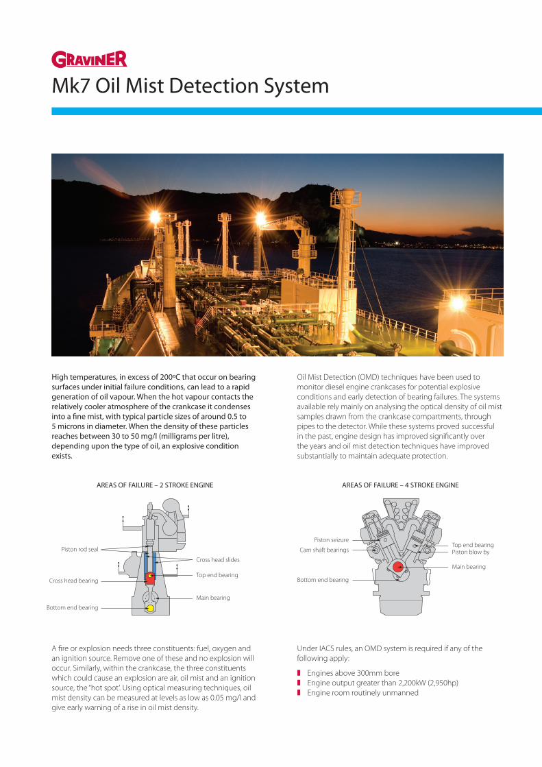
High temperatures, in excess of 200ºC that occur on bearing surfaces under initial failure conditions, can lead to a rapid generation of oil vapour. When the hot vapour contacts the relatively cooler atmosphere of the crankcase it condenses into a fine mist, with typical particle sizes of around 0.5 to 5 microns in diameter. When the density of these particles reaches between 30 to 50 mg/I (milligrams per litre), depending upon the type of oil, an explosive condition exists.
Oil Mist Detection (OMD) techniques have been used to monitor diesel engine crankcases for potential explosive conditions and early detection of bearing failures. The systems available rely mainly on analysing the optical density of oil mist samples drawn from the crankcase compartments, through pipes to the detector. While these systems proved successful in the past, engine design has improved significantly over the years and oil mist detection techniques have improved substantially to maintain adequate protection.
G R A V I N E R M k 6 O I L M I S T D E T E C T O R2
5-6 hours before any problems
became apparent. As engine design
improved, power outputs and bearing
loads increased and tolerances to
failure rapidly decreased.
To keep pace with these trends, oil
mist detector design improved in
terms of better sampling and faster
response times. The time has now
arrived where no further fundamental
improvements can be made to existing
system concepts, so a radical re-
appraisal of Oil Mist Detector
operating principles was required. The
Graviner Mk6 OMD is the result.
An unprotectedengine – no Oil MistDetector
Build-up of oil mistdue to ‘hotspot’being undetected
The possible result –ignition of oil mistcausing a crankcaseexplosion
American Bureau of Shipping (ABS)
Bureau Veritas (BV)
China Classification Society (CCS)
Det Norske Veritas (DNV)
Germanischer Lloyd (GL)
Korean Register of Shipping (KRS)
Lloyd’s Register (LR)
Nippon Kaiji Kyokai (NKK)
Polish Register of Shipping (PRS)
Registro Italiano Navale (RINA)
Russian Register of Shipping (RRS)
The crankcase of any diesel engine will contain oil mist which is formed by
condensation of oil vapour. The generation of oil vapour depends on
temperature. Under normal conditions, generation of mist and its re-
combination into liquid oil will be in equilibrium and a constant level of
oil mist density will be present.
When an incipient mechanical failure generates a ‘hotspot’, generation of
oil mist increases rapidly and far exceeds the re-combination rate. It is this
rapid increase in oil mist which must be identified at an early stage,
thereby giving warning of the incipient mechanical failure and initiating
actions that prevent the oil mist density rising to an explosive level.
Areas of Failure – 2 Stroke Engine
Piston Rod SealCross Head Slides
Top End Bearing
Main Bearing
Bottom End Bearing
Cross Head Bearing
Areas of Failure – 4 Stroke Engine
Piston SeizureTop End Bearing
Piston Blow by
Main Bearing
CamshaftBearings
Bottom EndBearing
What causes the problem?
A fire or explosion needs three constituents: fuel, oxygen and an ignition source. Remove one of these and no explosion will occur. Similarly, within the crankcase, the three constituents which could cause an explosion are air, oil mist and an ignition source, the “hot spot’. Using optical measuring techniques, oil mist density can be measured at levels as low as 0.05 mg/I and give early warning of a rise in oil mist density.
Under IACS rules, an OMD system is required if any of the following apply:
z Engines above 300mm borez Engine output greater than 2,200kW (2,950hp)z Engine room routinely unmanned
G R A V I N E R M k 6 O I L M I S T D E T E C T O R2
5-6 hours before any problems
became apparent. As engine design
improved, power outputs and bearing
loads increased and tolerances to
failure rapidly decreased.
To keep pace with these trends, oil
mist detector design improved in
terms of better sampling and faster
response times. The time has now
arrived where no further fundamental
improvements can be made to existing
system concepts, so a radical re-
appraisal of Oil Mist Detector
operating principles was required. The
Graviner Mk6 OMD is the result.
An unprotectedengine – no Oil MistDetector
Build-up of oil mistdue to ‘hotspot’being undetected
The possible result –ignition of oil mistcausing a crankcaseexplosion
American Bureau of Shipping (ABS)
Bureau Veritas (BV)
China Classification Society (CCS)
Det Norske Veritas (DNV)
Germanischer Lloyd (GL)
Korean Register of Shipping (KRS)
Lloyd’s Register (LR)
Nippon Kaiji Kyokai (NKK)
Polish Register of Shipping (PRS)
Registro Italiano Navale (RINA)
Russian Register of Shipping (RRS)
The crankcase of any diesel engine will contain oil mist which is formed by
condensation of oil vapour. The generation of oil vapour depends on
temperature. Under normal conditions, generation of mist and its re-
combination into liquid oil will be in equilibrium and a constant level of
oil mist density will be present.
When an incipient mechanical failure generates a ‘hotspot’, generation of
oil mist increases rapidly and far exceeds the re-combination rate. It is this
rapid increase in oil mist which must be identified at an early stage,
thereby giving warning of the incipient mechanical failure and initiating
actions that prevent the oil mist density rising to an explosive level.
Areas of Failure – 2 Stroke Engine
Piston Rod SealCross Head Slides
Top End Bearing
Main Bearing
Bottom End Bearing
Cross Head Bearing
Areas of Failure – 4 Stroke Engine
Piston SeizureTop End Bearing
Piston Blow by
Main Bearing
CamshaftBearings
Bottom EndBearing
What causes the problem?
Piston seizure
Cam shaft bearings
Bottom end bearing
Top end bearing
Main bearing
Piston blow by
AREAS OF FAILURE – 4 STROKE ENGINEAREAS OF FAILURE – 2 STROKE ENGINE
Piston rod seal
Cross head bearing
Bottom end bearing
Cross head slides
Main bearing
Top end bearing

Benefits of the Graviner Mk 7 OMD System include:
z Auto addressed system monitoring up to 10 detector heads per control unit
z Up to 10 control units per single system.z Suitable for both 2 stroke and 4 stroke engines. z Elimination of sample pipes - reduced installation costs.z Engine mounted Control Unit.z Remote Display Unit mounted in a safe area, typically the
Engine Control Room (ECR).
The Graviner Mk7 OMD System is an auto addressed oil mist detection system capable of monitoring up to 10 Control Units per system with each Control Unit having up to 10 detectors connected to it. This is achieved without external sample pipes and with minimum cabling. Each detector head monitors a single crank space and is a stand-alone device. On power up the detectors gather oil mist density data and convert it to a digital signal for transmission via the data lines in the detector cable to the Control Unit which is also mounted on the side of the engine. Alarm levels and Alarm output requirements are all set from either the Remote Indicator Display or a PC connected directly to the control unit.
In the event of a detector fault, that detector can be isolated without affecting the function of the other detectors on the engine. The system will continue to operate while the faulty detector is replaced, repaired or maintenance is carried out.
The Mk7 detectors still use optical sensing; (light scatter) as it’s detection method and continually monitors the oil mist density in the crank space to which it is connected. In addition, it self checks for any internal faults. The Control Unit interrogates each detector in turn, identifies the position connected at the Control Unit, the oil mist density value and determines the status of the detector.
The Control Unit can be supplied with or without a control membrane. The control membrane has LED indication for detectors connected, push buttons for isolation and de-isolation of detectors, as well as pushbuttons for Accepting and Resetting Alarms.
The Mk7 OMD System is tested and approved in accordance with IACS M67/M10 by the following Class Societies:
z American Bureau of Shippingz Bureau Veritasz China Classification Societyz Det Norske Veritasz Germanischer Lloydz Korean Register of Shippingz Lloyd’s Registerz Nippon Kaiji Kyokaiz Polish Register of Shippingz Registro Italiano Navalez Russian Maritime Register of Shipping
Also approved by MAN Diesel 2 Stroke and Wartsila 2 Stroke
The Remote Display Unit houses a 7.5” LCD Touch Screen display that shows, on demand, the signal from each detector and indicates the oil mist level for each engine and when required each detector as well as the status of the system. In the event of an alarm, the display immediately shows the oil mist levels for the relevant engine. It also enables the individual readings of each detector on the engine to be displayed on demand and automatically under alarm conditions.
Kidde Fire Protection, Thame Park Road, Thame, Oxfordshire OX9 3RT, United KingdomTel +44 (0)1844 265003 • Email: [email protected] • Web: www.kfp.co.uk
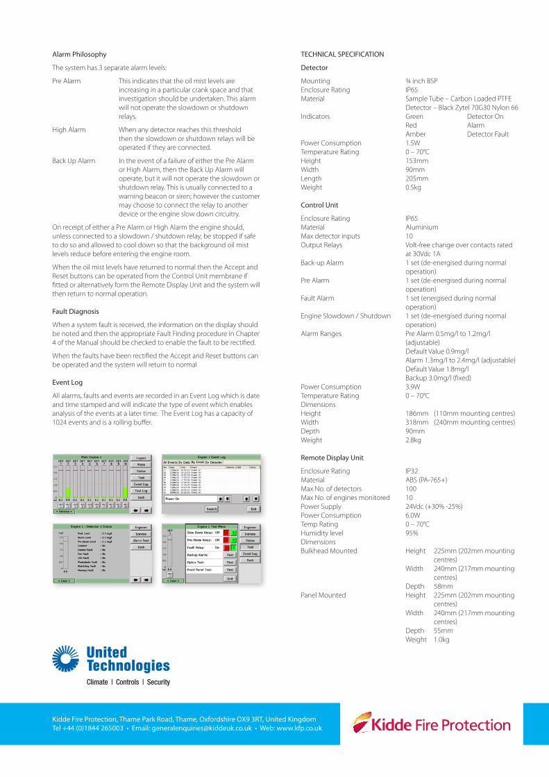
Alarm Philosophy
The system has 3 separate alarm levels:
Pre Alarm This indicates that the oil mist levels are increasing in a particular crank space and that investigation should be undertaken. This alarm will not operate the slowdown or shutdown relays.
High Alarm When any detector reaches this threshold then the slowdown or shutdown relays will be operated if they are connected.
Back Up Alarm In the event of a failure of either the Pre Alarm or High Alarm, then the Back Up Alarm will operate, but it will not operate the slowdown or shutdown relay. This is usually connected to a warning beacon or siren; however the customer may choose to connect the relay to another device or the engine slow down circuitry.
On receipt of either a Pre Alarm or High Alarm the engine should, unless connected to a slowdown / shutdown relay, be stopped if safe to do so and allowed to cool down so that the background oil mist levels reduce before entering the engine room.
When the oil mist levels have returned to normal then the Accept and Reset buttons can be operated from the Control Unit membrane if fitted or alternatively form the Remote Display Unit and the system will then return to normal operation.
Fault Diagnosis
When a system fault is received, the information on the display should be noted and then the appropriate Fault Finding procedure in Chapter 4 of the Manual should be checked to enable the fault to be rectified.
When the faults have been rectified the Accept and Reset buttons can be operated and the system will return to normal
Event Log
All alarms, faults and events are recorded in an Event Log which is date and time stamped and will indicate the type of event which enables analysis of the events at a later time. The Event Log has a capacity of 1024 events and is a rolling buffer.
TECHNICAL SPECIFICATION
Detector
Mounting ¾ inch BSPEnclosure Rating IP65Material Sample Tube – Carbon Loaded PTFE Detector – Black Zytel 70G30 Nylon 66Indicators Green Detector On Red Alarm Amber Detector FaultPower Consumption 1.5WTemperature Rating 0 – 70°C Height 153mmWidth 90mmLength 205mmWeight 0.5kg
Control Unit
Enclosure Rating IP65Material AluminiumMax detector inputs 10Output Relays Volt-free change over contacts rated at 30Vdc 1ABack-up Alarm 1 set (de-energised during normal operation)Pre Alarm 1 set (de-energised during normal operation)Fault Alarm 1 set (energised during normal operation)Engine Slowdown / Shutdown 1 set (de-energised during normal operation)Alarm Ranges Pre Alarm 0.5mg/l to 1.2mg/l (adjustable) Default Value 0.9mg/l Alarm 1.3mg/l to 2.4mg/l (adjustable) Default Value 1.8mg/l Backup 3.0mg/l (fixed)Power Consumption 3.9WTemperature Rating 0 – 70°CDimensions Height 186mm (110mm mounting centres)Width 318mm (240mm mounting centres)Depth 90mmWeight 2.8kg
Remote Display Unit
Enclosure Rating IP32Material ABS (PA-765+)Max No. of detectors 100Max No. of engines monitored 10Power Supply 24Vdc (+30% -25%)Power Consumption 6.0WTemp Rating 0 – 70°CHumidity level 95%DimensionsBulkhead Mounted Height 225mm (202mm mounting centres) Width 240mm (217mm mounting centres) Depth 58mmPanel Mounted Height 225mm (202mm mounting centres) Width 240mm (217mm mounting centres) Depth 55mm Weight 1.0kg