Embed Size (px)
Citation preview
1
Upper Limit Temperature Protection MICROTEMP® thermal cutoffs from Therm-O-Disc offer an accurate, reliable solution to the need for upper limit temperature protection. Known as a thermal fuse, thermal link, or TCO, the MICROTEMP® thermal cutoff provides protection against overheating by interrupting an electrical circuit when operating temperatures exceed the rated temperature of the cutoff.
MICROTEMP® Features: • One-shot operation cuts off electrical power• Current interrupt capacity up to 25 amps @ 250VAC• Low resistance• Compact size
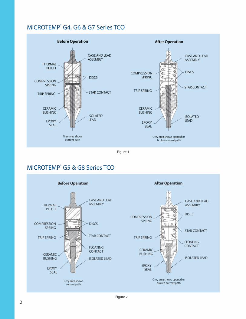
Operating Principle of the MICROTEMP® TCO The active trigger mechanism of the thermal cutoff is an exclusively formulated, electrically nonconductive pellet. Under normal operating temperatures, the solid pellet holds spring-loaded contacts closed.
When a predetermined temperature is reached, the pellet melts, allowing the compression spring to relax. The trip spring then slides the contact away from the lead and the circuit is opened (see figures 1 and 2).
After a MICROTEMP® thermal cutoff opens a circuit, the TCO needs to be replaced. This replacement procedure must include correction of the fault condition before the product is operated again.
MICROTEMP® Thermal Cutoffs: INTRODUCTION
2
THERMALPELLET
COMPRESSIONSPRING
TRIP SPRING
CERAMICBUSHING
CASE AND LEADASSEMBLY
DISCS
STAR CONTACT
ISOLATEDLEAD
Before Operation
Grey area showscurrent path
EPOXYSEAL
COMPRESSIONSPRING
TRIP SPRING
CERAMICBUSHING
CASE AND LEADASSEMBLY
DISCS
STAR CONTACT
ISOLATEDLEAD
After Operation
Grey area shows opened or broken current path
EPOXYSEAL
MICROTEMP® G4, G6 & G7 Series TCO
THERMALPELLET
COMPRESSIONSPRING
TRIP SPRING
CERAMICBUSHING
CASE AND LEADASSEMBLY
DISCS
STAR CONTACT
FLOATINGCONTACT
Before Operation
Grey area showscurrent path
ISOLATED LEAD
EPOXYSEAL
COMPRESSIONSPRING
TRIP SPRING
CERAMICBUSHING
CASE AND LEADASSEMBLY
DISCS
STAR CONTACT
ISOLATED LEAD
After Operation
Grey area shows opened orbroken current path
FLOATINGCONTACT
EPOXYSEAL
MICROTEMP® G5 & G8 Series TCO
Figure 1
Figure 2

MICROTEMP® thermal cutoffs are available in a range of temperatures and electrical ratings to meet application requirements (see Microtemp® Operating Temperature Summary and Electrical Rating Summary on page 4). There are 5 primary types of thermal cutoffs available. Standard dimensions of each TCO series are shown on page 4.
G Series: This “Global” series or G designation represents the world standard in thermal cutoffs. MICROTEMP® TCOs were the first chemical-pellet spring-type TCO ever developed and continue to be the thermal cutoff of choice for over 35 years.
E Series: This new “Environmentally” friendly series holds Agency recognition equivalent to the G series and has been designed to comply with the Restriction of Hazardous Substances in Electrical and Electronic Equipment (ROHS) Directive (2002/95/EC). None of the substances specified in this Directive have been intentionally incorporated into the E-series products.
G4 Series Rated for continuous operating currents up to 10 amps @ 250VAC (15 amps @ 120VAC, 5 amps @ 24VDC), the G4 series MICROTEMP® TCO is the industry standard for over-temperature protection. The G4 series is applied to millions of appliances and personal care products each year, providing reliable back-up protection for temperature controlling thermostats and other over-temperature conditions. The G4 series is also widely applied in office machines, portable heaters and industrial equipment as a thermal safeguard.
G5 Series Designed for higher voltage and current applications than the G4, the G5 series MICROTEMP® TCO is rated for operating currents up to 20 amps @ 250VAC and 277 VAC (25 amps @ 120VAC). Similar in appearance to the G4 series, the G5 series has a different internal construction designed for interrupting higher currents and withstanding higher temperatures.
G6 Series The G6 series MICROTEMP® TCO can be utilized in applications where a higher maximum-overshoot temperature rating is not required, yet it is rated for operating currents up to 16 amps @ 250VAC. It is the same physical size as the G4, G5 and G8 series TCOs.
G7 Series The G7 series MICROTEMP® TCO is designed to satisfy applications requiring miniaturized components that do not need maximum current interrupt capability. The G7 is just 2/3 the size of the G4 and G5, and with a current interrupting capability of 5 amps @ 250VAC (5 amps @ 24VDC), it is capable of meeting the requirements of transformers, motors, battery packs and electronic circuit applications.
G8 Series Designed for very high-current applications such as major appliances and high-wattage electric heat packages, the G8 series MICROTEMP® TCO is rated for operating currents up to 25 amps @ 250VAC (20 amps @ 277VAC). More economical than electromechanical bimetal-type one shot devices, it can be utilized in applications where its small size is an advantage in terms of mounting (it’s the same physical size as the G4, G5 and G6 series TCOs) and thermal response.
3
MICROTEMP® Thermal Cutoffs: TYPES & SPECIFICATIONS

Tm – Maximum overshoot temperature:
temperature up to which TCO will not change status
Tf – Functioning open temperature
tolerance: +0, -5°C Th
– Maximum temperature of the MICROTEMP® TCO measured at the case end of the thermal cutoff at which the thermal cutoff can be maintained for a period for 168 hours without opening. NOTE: it is advised that TCOs are not exposed to continuous operating temperatures in excess of Tf -25°C.
C.T.I.
– Comparative tracking index (all primary thermal cutoffs): 250VAC
NOTE: G4, G5, G6 ,G7 and G8 series TCOs with TF ≥ 175°C comply with UL conductive heat aging (CHAT)
requirements.
4
MICROTEMP® TCO Operating Temperature Summary
MICROTEMP® TCOStandard Dimensions
Electrical Rating Summary
Dimensions - Inches (Millimeters) G4, G5, G6, Z6 & G8 Series G7 Series
StandardLeads
A Overall Length ± .12 (±3.0)B Case Lead Length ± .06 (±1.5)
2.51 (63.8)1.38 (34.9)
N/AN/A
LongLeads
A Overall Length ± .12 (±3.0)B Case Lead Length ± .06 (±1.5)
3.26 (82.9)1.38 (34.9)
3.26 (82.9)1.38 (34.9)
Lead Materialand Diameter
C Case Lead Tin Plated CopperD Epoxy Lead Silver Plated Copper
0.040 (1.0)0.040 (1.0)
(0.023 (.57)(0.023 (.57)
CaseDimensions
E Case Length (Reference)F Case Diameter (Reference)
0.58 (14.7)0.158 (4.0)
0.38 (9.6)0.118 (3.0)
5
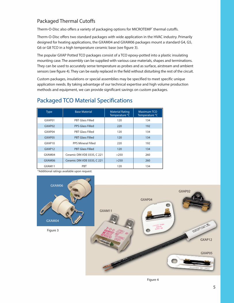
Packaged Thermal Cutoffs Therm-O-Disc also offers a variety of packaging options for MICROTEMP® thermal cutoffs.
Therm-O-Disc offers two standard packages with wide application in the HVAC industry. Primarily designed for heating applications, the GXAM04 and GXAM06 packages mount a standard G4, G5, G6 or G8 TCO in a high temperature ceramic base (see figure 3).
The popular GXAP Potted TCO packages consist of a TCO epoxy-potted into a plastic insulating mounting case. The assembly can be supplied with various case materials, shapes and terminations. They can be used to accurately sense temperature as probes and as surface, airstream and ambient sensors (see figure 4). They can be easily replaced in the field without disturbing the rest of the circuit.
Custom packages, insulations or special assemblies may be specified to meet specific unique application needs. By taking advantage of our technical expertise and high volume production methods and equipment, we can provide significant savings on custom packages.
Packaged TCO Material Specifications
Figure 4
GXAP04
GXAP02
GXAP12
GXAP05
Type Base Material Material Rating Maximum TCO Temperature °C Temperature °C
GXAP01 PBT Glass Filled 120 134
GXAP02 PPS Glass Filled 220 192
GXAP04 PBT Glass Filled 120 134
GXAP05 PBT Glass Filled 120 134
GXAP10 PPS Mineral Filled 220 192
GXAP12 PBT Glass Filled 120 134
GXAM04 Ceramic DIN VDE 0335, C 221 >250 260
GXAM06 Ceramic DIN VDE 0335, C 221 >250 260
GXAM11 PBT 120 134
Figure 3
GXAM04
GXAM06
*Additional ratings available upon request.
GXAM11

6
Lead Configurations The MICROTEMP® TCO can be furnished with virtually any lead configuration specified for an application. Lead curls are available to match most sizes of screws along with varying lead lengths and lead forms.
All types of terminations, such as quick connects, ring terminals and blade terminals, are available at additional cost. In addition, tape and reel packaging can be specified to meet high volume requirements.
Temperature Ratings MICROTEMP® thermal cutoffs are available in a wide range of opening temperatures, providing designers a high degree of flexibility (see Microtemp® TCO Operating Temperature Summary at the top of page 4). Determining the correct TCO temperature calibration requires significant application testing.
The proper calibration will be affected by application variables such as I2R self heating of the TCO, heat transfer through insulation and heat dissipation due to heat sinking and air flow. Thermocoupled TCO Test Samples (TTTS), that match the physical and electrical characteristics of a functional TCO, are available to help evaluate application specific variables.
For more information on testing and installing MICROTEMP® TCOs, please review the MICROTEMP® Thermal Cutoff Application Notes section.
Direct Current (DC) Applications The G4 and G7 series MICROTEMP® thermal cutoffs have published electrical ratings for direct current (DC) applications. Current interruption capacity in DC circuits is highly application sensitive.
Therm-O-Disc recommends thorough testing of DC electrical applications using the testing guidelines in Therm-O-Disc’s MICROTEMP® thermal cutoff technical information section.
Samples and QuotationsMICROTEMP® TCO samples and Thermocoupled TCO Test Samples (TTTS) are readily available for determining the correct response and desired performance in an application. For more information on MICROTEMP® TCOs, call a Therm-O-Disc sales engineer at 419-525-8300.

7
Lead Cutting
Dimension A Dimension B Dimension C
0.95 (24.2) 0.22 (5.6) 0.73 (18.6)
DIM. A
DIM. C DIM. B
Minimum DimensionsInches (millimeters)
Tape and Reel Packaging
F 0.060(1.5)
DIM. A
DIM. B
DIM. F
F0.031(0.8)
(PITCH MEASURED AT TAPE ON MICROTEMP SIDE)
DIM. D
DIM. C
DimensionsInches (millimeters)
Item Dim. A Dim. B Dim. C Dim. D Dim. E Dim. F
GXAA0900TTTC 1.66 (42.1) 2.80 (71.1) 1.38 (35.1) 3.26 (82.8) 3.60 (91.4) 0.200 (5.1)
G7FA0900TTTC 1.66 (42.1) 2.80 (71.1) 1.38 (35.1) 3.26 (82.8) 3.60 (91.4) 0.197 (5.0)

8
Product Nomenclature
MICROTEMP® TCO
MICROTEMP® TCO Packages
G Z X X XX RR TTTC
G – Rating type(G – Global, Y-Non Agency)
Z – Internal construction(4, 5, 6, 7, 8, 9)
X – Case material and lead wire(A, C, D, F)
TTTC – Maximumopen temperature in °C
RR – Assembly modifications(Plating, terminal bend, stenciling)
XX – Specific package construction(00-99)
X – General packages TCO type(Configuration, potted, mounting base, etc.)
As shown above, Therm-O-Disc MICROTEMP® TCOs follow a consistent product nomenclature that identifies the basic product type, lead wire size, special features and packaging options. For example, a standard G4 series TCO calibrat-ed to open at 192°C would have a part number G4A00192C.
MICROTEMP® TCO Product MarkingsPrimary TCOs Secondary Packages
XXXXXXXX Special customer identification XXXXXXXXX Special customer identification (when required, up to 9 characters) (when required, up to 9 characters)
MICROTEMP® Registered trademark MICROTEMP® Registered trademark
P ZZZZZ (P) Manufacturing plant; (may be T-O-D) (ZZZZZ) Date code G Z X XX RR Part number (see figure 7)
G Z X XX Part number (see figure 7) TF TTTC P ZZ (TF TTTC) Maximum open temperature °C;
TF TTTC ( ) Underwriters Labs logo; (P) Manufacturing plant location; (TF TTTC) Maximum open (ZZ) Manufacture date code; temperature °C ( ) Underwriters Labs logo
8

9
MICROTEMP® thermal cutoffs, available in a variety of standard and custom configurations, provide reliable one-shot, over-temperature protection in a wide range of applications. Performance can be affected by installation method and proper location of the thermal cutoff. Both application and installation are important in the overall performance of the product, and thorough testing is neces-sary for both AC and DC applications. The following guidelines will answer most questions concern-ing these two subjects.
Application of Thermal CutoffsA thermal measurement procedure that utilizes a Thermocoupled TCO Test Sample (TTTS) can assist in determining the appropriate calibration temperature and design location of MICROTEMP® thermal cutoffs. The TTTS matches the electrical characteristics of the thermal cutoff but does not have thermally responsive parts. The TTTS is supplied with a thermocouple attached to the case of the thermal cutoff (see figure 5).
Figure 5
View of required thermocouple attachment before soldering
Dummy cutoffs can be supplied with Type J, Type T or Type K thermocouples. Other thermocouple types can usually be supplied upon request at a nominal charge.
Location Sufficient time and effort must be used to determine the proper and most desirable location for a thermal cutoff. The employment of infrared thermography, or a sufficient number of thermocouples to identify the highest temperature areas in the product requiring protection during normal operation and fault conditions, should be considered. The location that provides the largest differential between these two conditions is generally most desirable.
MICROTEMP® Thermal Cutoff
APPLICATION NOTES
10
Calibration Temperature It is necessary to select a thermal cutoff rating above the maximum temperature experienced during normal operation, including expected short-term temperature overshoots. The temperatures experienced by the thermal cutoff during normal operation will determine the life expectancy for the thermal cutoff. If the thermal cutoff rating is too close to the temperature experienced during normal operation (including overshoot temperatures after opening of a thermostat, etc.), the probability of a nuisance trip increases. Nuisance trips are caused by pellet shrinkage due to repeated operation at temperatures near but below calibration temperature, or excessive thermal gradients across the case of the TCO and its leads (see “Thermal Gradients”).
Therm-O-Disc has compiled standard life curves by subjecting MICROTEMP® thermal cutoffs to very controlled temperatures for extended time periods under ideal laboratory conditions. Therefore, these standard life curves should be used only as a guideline. Comparison of measured tempera-tures to MICROTEMP® thermal cutoff standard life curves should not replace customer life testing using functional thermal cutoffs for the particular application. The design engineer must make the trade-off between response and life of the TCO based on product requirements. It is important to remember that temperatures experienced in actual application will vary from unit to unit.
Test ProcedureInstall the Thermocoupled TCO Test Sample (TTTS) in the electrical circuit to be opened in the event of a fault condition. Position it in the area that has been selected to be protected within the product based on prior determinations of the maximum permissible temperatures to be allowed. The TTTS should be installed using the same mounting and electrical connection that will be used for functional TCOs in production. Connect the thermocouple leads to a digital temperature measuring device to record temperatures. The product to be protected can now be operated, and the normal operating temperature monitored. Note that the TTTS is not a functional TCO and therefore will not open the circuit in the test setup.

11
THERMAL CUTOFF "DUMMY"
TERMINAL OR SPLICE
ELECTRICAL INSULATOR
CONNECTNG CONDUIT WIRE
THERMOCOUPLE
TEMPERATURE OR VOLTAGE MEASURING DEVICE
Figure 6
Figure 6 illustrates a typical installation of a TTTS. Note that the body of the TTTS is at the same potential as the connecting circuit; therefore, it must be electrically isolated from the surface against which the cutoff is mounted. Also note that the thermocouple wire is at the same poten-tial as the connecting circuit.
CAUTION . . . To avoid a false reading of the unit under test, thermocouple wires must not make contact with each other except at the temperature sensing junction.
CAUTION . . . Ensure that the thermocouple wire insulation will provide isolation against short-circuiting and shock hazards.
CAUTION . . . The terminal of the temperature measuring instrument, to which the thermocouple is attached, will be at the same potential as the connecting circuit wire. This instrument must be electrically isolated and considerable caution must be exercised in its use, since one of the thermocouple terminals is frequently grounded to the instrument chassis.
Before using measuring equipment powered directly from standard line voltages, check operation manuals. Be sure line voltages impressed on the thermocouple wires by the TTTS will not cause damage to the instrument.
The more closely the actual operating and ambient conditions can be simulated during test, the more valid the test results will be. These tests are necessary to empirically include the variable factors that need to be considered to select the properly rated thermal cutoffs. These factors include, but are not limited to, the heating effect of the current through the cutoff, adjoining
12
terminals and leads, heating or cooling effect of the terminals and external leads, rate of temperature rise, air flow, shock, vibration and other environmental and operating conditions unique to the application.
The product and application being tested will determine the number of cycles that must be run to determine the maximum “normal” operating temperature. “Overshoot” temperatures should be included in the determination of the maximum “normal” operating temperature. The overshoot temperature is often considerably higher than the temperature reached at the moment the thermostat opens. The conclusion of these tests will provide the maximum “normal” operating temperature at the thermal cutoff (at maximum anticipated voltage, ambient temperature, etc). The overshoot temperature seen by the thermal cutoff after the thermal cutoff opens in the application must also be carefully examined and compared to Tmax.
Manufacturing tolerances and variations should be carefully considered, and a sufficient number of units evaluated, to provide a statistical basis on which to determine the operating overshoot temperatures.
After obtaining the above information, test the product under fault conditions and monitor to determine that desired fault condition temperatures are not exceeded.
Where there are a variety of fault conditions, (e.g., short-circuited thermostats and transformer secondaries, locked motor rotors and solenoids, high ambient temperatures, restricted or blocked airflow, etc.), consideration should be given to multiple fault conditions which could occur simultaneously during the lifetime of the product, and to faults which may cause localized overheating in areas away from the TCO.
When the fault conditions have been set up, note the temperature of the TTTS when the maximum desired temperature limit is reached. At this point the circuit is manually interrupted. This test should be run several times, in several different units. In some applications, it will not be possible to “save” the tested item from damage, but only prevent the product from creating an external fire or electrical hazard. Damaged products should not be retested, since the results may not be the same as with undamaged units. The MICROTEMP® thermal cutoff ratings selected should be equal to or less than the temperature recorded at the TTTS at the time the maximum desired temperature is reached.
CAUTION . . . Excessive overshoot temperatures after the opening of the thermal cutoff may cause dielectric breakdown of the thermal cutoff and allow reconduction to occur. Functional thermal cutoffs should be tested to verify proper operation of the thermal cutoffs in the application (see Microtemp® TCO Operating Temperature Summary and Electrical Rating Summary on page 4).

13
Substitute actual thermal cutoffs in a sufficient number of finished products and re-run the tests to obtain statistical verification of the results. For multiple TCO applications, test functional thermal cutoffs under fault conditions so that the product overheats and each thermal cutoff is independently called upon to interrupt the flow of current. Each thermal cutoff should open the circuit independently of any other over-temperature limit controls, with product damage not exceeding an acceptable level. This test should be run using the maximum voltage and current; the thermal cutoff will be expected to interrupt and hold open.
Installation of Thermal CutoffsThe performance of a MICROTEMP® thermal cutoff can be affected by installation methods such as soldering, welding, splicing, lead bending, insulation, clamping and mounting. Certain precautions should be taken during installation to ensure that the MICROTEMP® thermal cutoff is not damaged, which may cause it to not operate in its intended manner. Likewise, care should be taken during installation to ensure that the TCO in every unit experiences the expected temperature range environment previously determined during the calibration temperature selection. Thefollowing guidelines should be used to minimize undesirable conditions that can result from improper installation practices.
Soldering LeadsThermal cutoff leads should be heat sinked during the soldering operation (see figure 7). If excessive heat is conducted by the leads into the thermal cutoff, it can shorten the life of the TCO. In addition, excessive lead temperatures can damage the epoxy and possibly result in the TCO failing to open. More heat sinking is necessary for thermal cutoffs with low temperature ratings.
HEAT SINK HERE
SOLDER SOLDER
Figure 7

14
Test samples should be x-rayed before and after the soldering operation. The size of the chemical pellet should be measured with an optical comparator or a toolmaker’s microscope to verify that no shrinkage has occurred during the soldering operation (see figure 8). The epoxy seal should retain its size and shape and not discolor. If the chemical pellet or the epoxy have changed size as a result of the soldering operation more heat sinking is required.
EPOXY SEALBARRELSPRING
THERMAL PELLET
ISOLATEDLEAD
TRIPSPRING
CASE &LEAD ASSEMBLY
Figure 8
Welding LeadsThe thermal cutoff leads may also need to be heat sinked during a welding operation (see figure 9). The same precautions and tests described in the soldering section should also be followed for welded leads.
WELD POINTS
HEAT SINK HERE
Figure 9
To avoid damaging or welding internal parts, care should be taken that none of the welding current is conducted through the TCO. A welding current of hundreds of amperes can weld the internal parts together, resulting in the TCO failing to open.
TCO leads must be supported during the weld operation to prevent breaking the thermal cutoff epoxy seal.

15
Splices & TerminalsInsecure splices and terminations may produce high resistance junctions which can cause self heating (I2R) as power is dissipated across these junctions during product operation.
Heat from these hot spots can flow down the thermal cutoff leads and increase the temperature of the thermal cutoff (see figure 10). Nuisance openings of the thermal cutoffs or degradation of the epoxy seal can occur as a result of the heat generated by high resistance junctions. The splice or termination junction may initially measure low resistance, but can change to a much higher resistance after several temperature cycles. It is generally better to splice MICROTEMP® thermal cutoff leads to stranded lead wires rather than solid wires as the stranded wire may be crimped tighter and maintain better electrical contact during temperature cycling.
SPLICE HEAT FLOW HEAT FLOW
NUT
LOCKWASHER
BOLTSPLICE
TERMINATION
SPLICE
Figure 10
The temperature capabilities of the splice and/or termination should be considered. For example, solder back-up should be considered for splices of terminations in applications cycled at temperatures exceeding 150°C.
Bending LeadsWhen configuring leads, special care must be exercised in supporting the leads at each end near the body of the thermal cutoff so that the case will not be distorted or the epoxy will not be cracked or broken. At least 0.125” (3mm) should be maintained between the epoxy seal and any lead bends (see figure 11).

16
.09 MIN.
(2.3 mm)
.04 MIN. RAD.
(1.0 mm)
.70 MIN. (17.8 mm)
Figure 11
Dimensions are shown in inches (millimeters).
Thermal GradientsIdeal TCO placement subjects the entire TCO case, leads, epoxy seal and internal components to a uniform temperature environment.
Care should be exercised in the placement of the TCO to minimize thermal gradients across the TCO body. In certain applications, the TCO can be mounted in a position where heat is conducted to the body of the TCO through one of the leads, resulting in thermal gradients across the TCO. Over time, the TCO life can be reduced by thermal gradients if the isolated (epoxy) lead is at a consistently lower temperature than the case lead. Long term testing is recommended in determining whether these conditions exist in the application.
To minimize the effects of thermal gradients and the temperature increase of the TCO body from this heat flow, attach the isolated (epoxy) lead, rather than the case lead, to the heat source.
TTTS can be supplied with thermocouples on both ends to facilitate gradient evaluations.
Temperature LimitsThe temperatures experienced during normal operation, including expected temperature over-shoots, will determine the life expectancy of the TCO. Nuisance trips can result if the thermal cut-off rating is too close to the temperatures experienced during normal operation. Thermal cutoffs of any temperature rating should not be subjected to continuous normal temperatures in excess of 200°C. Additionally, overshoot temperatures after the opening of the thermal cutoff should be minimized to avoid dielectric breakdown and reconduction of the thermal cutoff.

17
CAUTION . . . The thermal cutoff may fail to open the electrical circuit under certain conditions. Distortion of the case, breaking or cracking the seal, exposing the epoxy seal to cleaning solvents, compression of the leads and current surges that exceed the operating specifications of the thermal cutoff may cause the thermal cutoff not to open. In addition, pellet shrinkage due to thermal aging under some circumstances may also result in failure to open. Finally, a very low rate of temperature rise may produce conditions that may also result in failure to open. Care must be taken to avoid any mishandling or misapplication of the thermal cutoff.
CAUTION . . . Although TCOs are highly reliable devices, a TCO may fail to open in operation for one or more of the reasons set forth above. These conditions must be taken into account by the product design engineer in determining the level of reliability needed for the application. If failure of the TCO to open could result in personal injury or property damage, the product design engineer may want to consider using one or more redundant TCOs of different ratings to achieve the desired level of reliability. A number of consumer product design engineers have incorporated redundant TCOs of different ratings in their designs for this reason.
Definition of TermsMaximum Open Temperature or Rated Functioning Temperature (Tf, TF):The maximum temperature at which the thermal cutoff changes its state of conductivity to open circuit with detection current as the only load. The rated functioning temperature is measured during a temperature rise of approximately 0.5°C per minute.
Holding Temperature (Th, TH):Maximum temperature of the MICROTEMP® TCO measured at the case end of the thermal cutoff at which the thermal cutoff can be maintained for a period for 168 hours without opening. NOTE: it is advised that TCOs are not exposed to continuous operating temperatures in excess of Tf -25°C.
Maximum Overshoot Temperature or Maximum Temperature Limit (Tm, TM):The maximum temperature at which the thermal cutoff, having changed its state of conductivity, can be maintained at twice rated voltage for a specified period of time, during which its mechanical and electrical properties will not be impaired.
Rated Voltage:The maximum voltage that can be applied to the circuit in which the thermal cutoff is used.
Rated Current:The maximum current that the thermal cutoff is rated to interrupt at the rated voltage.

18
Agency RecognitionMICROTEMP® thermal cutoffs are recognized by the following major agencies:
PSE
UL BEAB METI CSA CCC VDE
Underwriters British Ministry of Canadian China Varband Laboratories Inc. Electrotechnical Economy, Trade Standards Cumpulsary Deutscher (USA) Approvals Board and Industry of Association Product Electrotechniker e.V. Japan Certification (F. R. G.)
MICROTEMP® thermal cutoffs are recognized by the major approval agencies throughout the world for AC circuit applications. These agency electrical ratings can be used as a guideline when evalu-ating specific thermal cutoff applications. However, the electrical and thermal conditions to which the thermal cutoff may be exposed in an application may differ significantly from agency test con-ditions. Accordingly, customers should not rely solely on agency ratings but rather must perform adequate testing on the particular application to confirm that the TCO selected is appropriate for that application and will operate as intended.
Important NoticeUsers must determine the suitability of the control for their application, including the level of reliability required, and are solely responsible for the function of the end-use product.
These controls contain exposed electrical components and are not intended to withstand exposure to water or other environmental contaminants which can compromise insulating components. Such exposure may result in insulation breakdown and accompanying localized electrical heating.
A control may remain permanently closed or open as a result of exposure to excessive mechanical, electrical, thermal or environmental conditions or at normal end-of-life. If failure of the control to operate could result in personal injury or property damage, the user should incorporate supplemental system control features to achieve the desired level of reliability and safety. For example, backup controls have been incorporated in a number of applications for this reason.