Embed Size (px)
Citation preview

1000 Technology Drive, Pittsburgh, PA 15219 645 Russell Street, Batesburg, SC 29006 SM 6800O
Copyright © 2008 SM 6800OUnion Switch & Signal Inc. January 2008
Microlok II®Serial-to-Ethernet Converter
(SEC)
US&S Part No. N16920401
Installation
Operation
Troubleshooting


SM 6800O, January 2008 i
Proprietary Notice
This document and its contents are the property of Union Switch & Signal Inc. hereinafter US&S). This document has been furnished to you on the following conditions: no right or license under any patents or any other proprietary right in respect of this document or its content is given or waived in supplying this document. This document or its content are not to be used or treated in any manner inconsistent with the rights of US&S, or to its detriment, and are not to be copied, reproduced, disclosed to others, or disposed of except with the prior written consent of US&S.
Important Notice US&S constantly strives to improve our products and keep our customers apprised of changes in technology. Following the recommendations contained in the attached service manual will provide our customers with optimum operational reliability. The data contained herein purports solely to describe the product, and does not create any warranties.
Within the scope of the attached manual, it is impossible to take into account every eventuality that may arise with technical equipment in service. Please consult your local US&S sales representative in the event of any irregularities with our product.
We expressly disclaim liability resulting from any improper handling or use of our equipment, even if these instructions contain no specific indication in this respect. We strongly recommend that only approved US&S spare parts are used as replacements.
.

Revision History
ii SM 6800O, January 2008
Revision History
Rev. Date Nature of Revision Original January 2008 Initial Issue

Table of Contents
SM 6800O, January 2008 v
Table of Contents
1 General Information ...................................................................................................... 1-1 1.1 Safety Summary.................................................................................................................... 1-1
1.2 Abbreviations and Acronyms................................................................................................. 1-1
1.3 Specifications ........................................................................................................................ 1-2
2 General Description ...................................................................................................... 2-1
3 Installation and Configuration ..................................................................................... 3-1 3.1 Power Source Cable Configuration ....................................................................................... 3-1
3.2 Serial Cable Configuration .................................................................................................... 3-2
3.3 Selecting the Ethernet Cable................................................................................................. 3-2
3.4 Installing the SEC Unit .......................................................................................................... 3-3
3.5 Configuring Internet Explorer to Access the SEC Configuration Screens ............................. 3-4
3.5.1 Checking Internet Explorer.......................................................................................... 3-5
3.5.2 Deleting Saved Temporary Internet Files.................................................................... 3-8
3.6 Connecting a New SEC to a PC for Configuration .............................................................. 3-10
3.7 Accessing the SEC Configuration Page.............................................................................. 3-11
3.8 Configuring the SEC............................................................................................................ 3-12
3.9 SEC Configuration Options ................................................................................................. 3-17
3.9.1 Changing Network Settings....................................................................................... 3-17
3.10 Uploading new SEC Firmware ............................................................................................ 3-18
3.11 Identifying IP Addresses of Digi-based Devices on a Network............................................ 3-20
3.12 Erasing the Existing Configuration File................................................................................ 3-22
4 Troubleshooting............................................................................................................ 4-1
5 Application Guidelines ................................................................................................. 5-1 5.1 Factory niacfg.ini File ............................................................................................................ 5-1
5.2 General Section Options ....................................................................................................... 5-3
5.2.1 Mode ....................................................................................................................... 5-4

Table of Contents
vi SM 6800O, January 2008
5.2.2 Bit Rate ....................................................................................................................... 5-4
5.2.3 IP Address................................................................................................................... 5-4
5.2.4 Netmask ...................................................................................................................... 5-4
5.2.5 Gateway ...................................................................................................................... 5-4
5.2.6 Broadcast .................................................................................................................... 5-4
5.2.7 Learn ....................................................................................................................... 5-5
5.2.8 Port ....................................................................................................................... 5-5
5.2.9 Pair ....................................................................................................................... 5-5
5.3 Static Routing Table .............................................................................................................. 5-6
5.3.1 UDP Section Options .................................................................................................. 5-6
5.3.2 TCP Section Options................................................................................................... 5-7
5.4 HMAC Section Options ......................................................................................................... 5-8
6 Parts List........................................................................................................................ 6-1
7 RAIL Team and Technical Support.............................................................................. 7-1

Table of Contents
SM 6800O, January 2008 vii
List of Figures
Figure 1-1 - Overall Dimensions of the SEC ................................................................................... 1-3 Figure 2-1 - SEC Front Panel.......................................................................................................... 2-2 Figure 3-1 - Power and WAGO Connectors.................................................................................... 3-1 Figure 3-2 - DB-9 Connector on the SEC ....................................................................................... 3-2 Figure 3-3 - SEC Wired to the Power Source, Microlok II, and PC................................................. 3-4 Figure 3-4 - Accessing the Internet Options on Internet Explorer Version 6. .................................. 3-5 Figure 3-5 - Connections Tab on the Internet Options Box............................................................. 3-6 Figure 3-6 - LAN Settings Pop-Up Box ........................................................................................... 3-7 Figure 3-7 - Proxy Settings Pop-Up Box ......................................................................................... 3-8 Figure 3-8 - Internet Explorer Internet Options Dialog Box ............................................................. 3-9 Figure 3-9 - Delete Files Confirmation Dialog Box.......................................................................... 3-9 Figure 3-10 - Low or No Connectivity Mode Balloon Message ..................................................... 3-10 Figure 3-11 - SEC Login Dialog .................................................................................................... 3-11 Figure 3-12 - SEC Configuration Home Page............................................................................... 3-12 Figure 3-13 - SEC Advanced Tools Page ..................................................................................... 3-13 Figure 3-14 - SEC Flash0/Directory Page..................................................................................... 3-14 Figure 3-15 - File Upload Page ..................................................................................................... 3-15 Figure 3-16 - FLASH0/Directory Page .......................................................................................... 3-15 Figure 3-17 - Back Button in Web Browser on FLASH0/Directory Page....................................... 3-16 Figure 3-18 - Advanced Tools Page ............................................................................................. 3-16 Figure 3-19 - Digi Module Front View Showing Yellow and Green LEDs ..................................... 3-17 Figure 3-20 - GENERAL Section of the niacfg.ini File................................................................... 3-18 Figure 3-21 - Command Line Shell Window ................................................................................. 3-19 Figure 3-22 - Digi Connect ME Tech Support Information Page................................................... 3-21 Figure 3-23 - Utilities Specific to Your Operating System ............................................................. 3-22 Figure 3-24 - Erases Flash Function Password Dialog Box.......................................................... 3-23 Figure 3-25 - Erase Flash Function Confirmation Page................................................................ 3-24

Table of Contents
viii SM 6800O, January 2008
List of Tables Table 1-1 - Operating Specifications............................................................................................... 1-2 Table 1-2 - Mechanical Specifications ............................................................................................ 1-3 Table 3-1 - SEC to Microlok II Connections .................................................................................... 3-2 Table 5-1 - Factory Configuration File............................................................................................. 5-1 Table 6-1 - Parts List ....................................................................................................................... 6-1

General Information
SM 6800O, January 2008 1-1
1 General Information This manual describes the installation, configuration, operation, and troubleshooting of the Serial-to-Ethernet Converter (SEC). The SEC is a device that converts Microlok II serial coded data to Ethernet coded data. This allows Microlok II to be connected to an internal or external network utilizing Microlok II Peer protocol to communicate vital and non-vital messages.
1.1 Safety Summary
Throughout this manual there are notes, cautions, and warnings that should be followed by the operator.
• • Notes provide additional information to the subject being discussed in a particular section of the
manual. • Cautions present considerations which, if ignored, could result in damage to the equipment. • Warnings present considerations which, if ignored, could result in personnel injury or even death.
Electrical equipment can have high voltage and high temperature areas. Caution should be exercised when working around electrical equipment.
Care must be taken to follow all local and railroad safety requirements.
1.2 Abbreviations and Acronyms
The following are abbreviations and acronyms used in this manual along with their associated meanings.
AAR Association of American Railroads
CAT5 Category 5 cable
DB D-subminiature, a common type of computer connector
DCD Data Carrier Detect
DHCP Dynamic Host Configuration Protocol
DIN Standardized 35 mm wide metal rail with hat-shaped cross section.
EMI Electromagnetic Interference
FRA Federal Railroad Administration
ftp File Transfer Protocol
HMAC Hash-keyed Message Authentication Code

General Information
1-2 SM 6800O, January 2008
IP Internet Protocol
LED light-emitting diode
MAC Media Access Control, a data communication protocol sub-layer
ME Micro-embedded
PC personal computer
RS-232 Recommended Standard 232
RX Receive
RXD Receive Data
RTS Request to Send
SEC Serial-to-Ethernet Converter
TCP Transmission Control Protocol
TX Transmit
TXD Transmit data
UDP User Datagram Protocol
US&S Union Switch & Signal
VDC volts direct current
1.3 Specifications
The Microlok II SEC meets all applicable environmental, EMI, and vibration tolerance specifications.
The operating specifications for the N16920401 SEC are shown in Table 1-1.
Table 1-1 - Operating Specifications
Parameter Value System Power Source Voltages +9.8 to +16.2VDC
Temperature Range -40° C to +70°C
Humidity 0% to 95% non-condensing
Vibration AAR/FRA compliant
EMI AAR/FRA compliant
The mechanical specifications for the N16920401 SEC are shown in Table 1-2 and illustrated in Figure 1-1.

General Information
SM 6800O, January 2008 1-3
Table 1-2 - Mechanical Specifications
Parameter Value Height 6.77 in. (17.2 cm)
Width 4.41 in. (11.2 cm) (not including the DIN rail Mounting Tabs)
Depth 1.38 in. (3.5 cm)
Weight 0.74 lb. (337g) for the wholly assembled unit.
Mounting Standard DIN Rail Mount
6.77
”R
EF.
(17.
2 cm
)
4 .4 1” REF. 1.38”(11.2 cm) (3.5 cm)
Figure 1-1 - Overall Dimensions of the SEC

General Information
1-4 SM 6800O, January 2008

General Description
SM 6800O, January 2008 2-1
2 General Description The Serial-to-Ethernet Converter (SEC) provides Ethernet network connectivity to Microlok II units. The SEC converts the Microlok II Peer messages from the Microlok II serial ports to Ethernet data which is then available to other devices across an Ethernet network. The SEC thus enables the routing of Microlok II Peer messages using the TCP and UDP network protocols. Conversely, the SEC converts Ethernet signals to serial data for use by a Microlok II unit.
Microlok II serial data placed on the network is also available for central office applications enabling Microlok II units to communicate with central office applications that support the Peer protocol. The SEC can route Peer messages to any destination that implements the Peer protocol.
The SEC supports the option of attaching the Hash-keyed Message Authentication Code (HMAC) to peer protocol messages.
The SEC functionally consists of the following:
• A serial protocol communication channel which translates between Microlok II RS-232 signals and Ethernet to allow Microlok II units to communicate with outside networks using Peer protocol.
• Power source circuitry which conditions a nominal 12-volt battery source to provide isolated power.
• An internal web server/interface that provides screens for configuring the SEC unit.
The SEC has a built-in web interface. Using this interface, you can inspect each unit's operational status and product information. You can also configure the unit through the web interface and even upgrade its firmware in the field. Access to the user interface is password protected. (See Sections 3.7 and 3.8.)
The SEC is packaged in a plastic box with tabs on the back for DIN rail mounting (Figure 1-1). The SEC requires a source voltage in the range of 9.8 to 16.2 VDC. The unit connects to the battery power source using a four-pin WAGO connector (J7091461910) on the front panel. This connector is supplied with the unit but must be wired by the user (Section 3.1). Power is indicated by a red LED on the front panel and is controlled with an On/Off rocker switch. A five-amp fuse (J071185), accessible from the front panel, protects the unit from excessive current. Figure 2-1 shows the front panel of the SEC.
The SEC provides translation for one serial communications channel between RS-232 and Ethernet. The RS-232 port connection is a DB-9 female connector mounted on the front panel (Serial Connection on Figure 2-1). This port supports both RX and TX signals.
The SEC Ethernet Connection uses an RJ45 connector. These two communication ports (Serial Connection and Ethernet Connection) are isolated from each other, from the system chassis, and from the system battery.

General Description
2-2 SM 6800O, January 2008
Figure 2-1 - SEC Front Panel

Installation and Configuration
SM 6800O, January 2008 3-1
3 Installation and Configuration This section describes the minimum system requirements for installing and configuring an SEC.
To install the SEC the following equipment is required:
• A PC with Internet Explorer Version 6.0 or higher. (These procedures are written for Internet Explorer 6, if your PC uses a different version of Internet Explorer; please check your IT department for any differences in the procedures.)
• A serial cable • A standard Ethernet cable (for connecting the SEC to an Ethernet network) • A crossover Ethernet cable (for connecting the SEC to a PC) • A WAGO power connector (US&S supplied)
3.1 Power Source Cable Configuration
Power is supplied through the front mounted WAGO cage clamp style connector. It is recommended that 14-18AWG wire be used for the power connections. The negative battery is connected to Pin 1 of the connector and the positive battery is connected to Pin 4 (Figure 3-1).
POWER CONNECTORORANGE on SEC
Battery Input9.8VDC - 16.2VDC
Battery Input9.8VDC - 16.2VDC
-
-
+
+
No keying is required for the power connector
1
1
2
2
3
3
4
4
WAGO Connector(J7091461910)
Figure 3-1 - Power and WAGO Connectors

Installation and Configuration
3-2 SM 6800O, January 2008
3.2 Serial Cable Configuration
The SEC is connected to a Microlok II RS-232 Comm port using a customer-supplied standard DB-9 connector which is connected to the Serial Connection port on the front panel of the SEC. The serial cable on the Microlok II end must have RTS (Request to Send) and DCD (Data Carrier Detect) jumpered together (see Table 3-1) (Refer to the Microlok II manuals The SEC’s pin assignments for the RS-232 DB-9 connectors are shown in Figure 3-2 and listed in Table 3-1.
SOCKET OR FEMALEDB-9 CONNECTOR
5 (SIG COMM)
4
3 (TXD)
2 (RXD)
1
9
8
7
6
Figure 3-2 - DB-9 Connector on the SEC
Table 3-1 - SEC to Microlok II Connections
SEC (DB-9) Microlok II Connection Pin No. Signal
2 RXD (Input) 3 TXD (Output) 5 Signal Common
Refer to the Microlok II Service Manual SM 6800B, Section 3.5 for connection to the Microlok II System. For Port 3, Jumper Pin C14, RTS (Output), to Pin E10, DCD (Input), and Jumper Pin E18, RXREF, to C18, Signal Common. For Port 4, Jumper Pin A14, RTS (Output), to Pin C16, DCD (Input).
3.3 Selecting the Ethernet Cable
The Ethernet port is a standard eight-pin RJ45 connector which uses any of the widely available Category 5 (CAT5) or better cable (standard off-the-shelf cable). An Ethernet crossover cable is required to connect the SEC directly to a PC and a standard Ethernet cable is used to connect the SEC to the network.

Installation and Configuration
SM 6800O, January 2008 3-3
3.4 Installing the SEC Unit
The SEC mounts on a standard DIN rail. The serial connection of the SEC must connect to a serial connector on the Microlok II unit using the proper cable, so the unit should be mounted no more than 50 feet away from the Microlok II unit.
1. Snap the SEC onto the DIN rail.
NOTE Because of serial and power cable limitations, the SEC should be located no further than 50 feet away from the Microlok II unit and the intended power source to which it will be connected.
2. With the On/Off rocker switch on the front of the SEC in the OFF position, insert the four-pin WAGO connector into its socket on the front of the SEC. Connect the power source by inserting the power leads into the WAGO connector (Figure 3-1).
3. Connect the serial cable to the Microlok II unit, and then to the SEC (Figure 3-3).
4. Apply power to the SEC by placing the On/Off rocker switch on the front of the SEC in the ON position.
5. Insert one end of an Ethernet crossover cable to the Ethernet connector of the SEC and the other end to the Network Interface Connector on the PC you will be using to configure the SEC unit (Figure 3-3).
NOTE An Ethernet crossover cable must be used to connect the SEC to the PC.
6. Configure Internet Explorer on the PC for accessing the SEC configuration screens. See Section 3.5 for the procedure.
7. Configure the SEC using the PC. See Section 3.7 through Section 3.9 for the procedures.
8. Disconnect the PC from the SEC by removing the Ethernet crossover cable from the SEC and connect the SEC to the network using a standard Ethernet cable.

Installation and Configuration
3-4 SM 6800O, January 2008
SERIAL CABLE
ETHERNET CROSSOVER CABLE
STANDARD ETHERNET CABLE
MICROLOK II
POWERSUPPLY
PC
ETHERNET NETWORK
SERIAL-TO-ETHERNETCONVERTER
+_
Figure 3-3 - SEC Wired to the Power Source, Microlok II, and PC
3.5 Configuring Internet Explorer to Access the SEC Configuration Screens
To be able to use Internet Explorer to access the configuration functions of the SEC, you may need to do one or both of the following: • Specify the IP address range used by the SEC in Internet Explorer's Settings
• Delete the Temporary Internet Files saved by Internet Explorer
This section describes each of these procedures.

Installation and Configuration
SM 6800O, January 2008 3-5
3.5.1 Checking Internet Explorer
You may need to configure your Internet Explorer settings to allow the browser to access the IP address range used by the SEC. The address range is specified by 169.254.*. To check Internet Explorer and to configure it, if necessary, do the following:
1. In the Internet Explorer Tools option click on Internet Options (Figure 3-4).
Figure 3-4 - Accessing the Internet Options on Internet Explorer Version 6.

Installation and Configuration
3-6 SM 6800O, January 2008
2. In the Internet Options pop up box, click on the Connections tab. (See Figure 3-5).
3. In the Connections tab, click on the LAN Settings button.
Figure 3-5 - Connections Tab on the Internet Options Box

Installation and Configuration
SM 6800O, January 2008 3-7
4. The LAN Settings pop-up box will open (Figure 3-6). If the “Use a proxy server for your LAN” isunchecked, leave it unchecked, and skip Steps 5 and 6. If the box is checked, proceed with Steps 5and 6.
5. Click on the Advanced button to open the Proxy Settings pop-up box.
Figure 3-6 - LAN Settings Pop-Up Box
Installation and Configuration
3-8 SM 6800O, January 2008
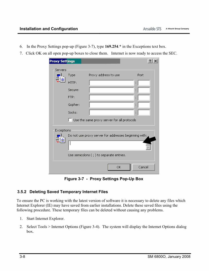
6. In the Proxy Settings pop-up (Figure 3-7), type 169.254.* in the Exceptions text box.
7. Click OK on all open pop-up boxes to close them. Internet is now ready to access the SEC.
Figure 3-7 - Proxy Settings Pop-Up Box
3.5.2 Deleting Saved Temporary Internet Files
To ensure the PC is working with the latest version of software it is necessary to delete any files which Internet Explorer (IE) may have saved from earlier installations. Delete these saved files using the following procedure. These temporary files can be deleted without causing any problems.
1. Start Internet Explorer.
2. Select Tools > Internet Options (Figure 3-4). The system will display the Internet Options dialogbox.

Installation and Configuration
SM 6800O, January 2008 3-9
3. Select the General tab (Figure 3-8).
Figure 3-8 - Internet Explorer Internet Options Dialog Box
4. Click on Delete Files button in the Temporary Internet files area. In response the system willdisplay a confirmation box asking if you want to delete the temporary Internet files (Figure 3-9).
Figure 3-9 - Delete Files Confirmation Dialog Box

Installation and Configuration
3-10 SM 6800O, January 2008
5. Click OK. The PC will then delete the temporary Internet files.
6. Click OK to close the Internet Options dialog box.
3.6 Connecting a New SEC to a PC for Configuration
You access the SEC configuration screen just as you would access a web site using a PC and Internet Explorer.
During the initial installation of the SEC, you must access the unit's configuration screens directly through its Ethernet port or through a hub or network switch that has no other unconfigured SECs connected to it. This is because all new SECs are set to the same IP address at the factory. If more than one device on a given network has the same IP address, none of those devices will be accessible.
Once the SEC is configured to communicate with the network, subsequent access and reconfiguring can be done from any PC connected to the network.
The Ethernet port of the SEC is set to IP address 169.254.1.10 at the factory. To use the Ethernet port in a network, you must set the IP address to a unique value using the following procedure.
1. Connect the PC to the SEC either directly with an Ethernet crossover cable, or through an Ethernet hub or switch using a standard Ethernet cable.
2. To configure the PC to communicate with the SEC, wait for the PC to go check its local area connections. A message will appear (Figure 3-10) that indicates the PC is in a limited connectivity mode. At this point you can access the SEC configuration page and set its IP address (Sections 3.7 and 3.8).
Figure 3-10 - Low or No Connectivity Mode Balloon Message
NOTE Be sure Internet Explorer’s Proxy settings allow for accessing the 169.254.* address range. See Section 3.5 for the procedure.

Installation and Configuration
SM 6800O, January 2008 3-11
3.7 Accessing the SEC Configuration Page
If the SEC unit is already functioning and connected to the network, you can access its configuration page from a PC anywhere on the network. See Section 3.11 for instructions on downloading a utility that can help you find the existing IP addresses of the SEC units on the network.
From the SEC configuration page you can view current network settings and access links to functions for reconfiguring the unit. Use the following procedure to access the SEC configuration page.
1. Using Internet Explorer, type the IP address, 169.254.1.10, into the address box of the browser and press the Enter key on your keyboard. Before granting you access to the configuration home page, the system will prompt you for a user name and password (Figure 3-11).
Figure 3-11 - SEC Login Dialog

Installation and Configuration
3-12 SM 6800O, January 2008
2. Enter advanced for the user name, and objctl for the password. The system will display the SECconfiguration page (Figure 3-12).
Figure 3-12 - SEC Configuration Home Page
In addition to a link to the Advanced Tools page, the SEC configuration page displays the part number and software version of the SEC, the MAC address, IP address, Subnet Mask, and Gateway address. The Mode is also displayed. Currently, only Peer Routing Mode is supported.
For information on configuring the SEC using the Advanced Tools page, see Section 3.8.
3.8 Configuring the SEC
All of the SEC configuration settings are maintained in the niacfg.ini file that resides in memory in the SEC. Configuring the SEC involves making changes to the niacfg.ini file.
The following procedure takes you through the process of making changes to the niacfg.ini file. Using this procedure, you will:
• Access the file residing on the SEC with Internet Explorer
• Download the file to your local PC
• Edit the file using a text editor
• Upload the edited file to the SEC memory
• Reboot the SEC

Installation and Configuration
SM 6800O, January 2008 3-13
NOTE Before proceeding with this procedure, delete Internet Explorer's saved temporary Internet files. See Section 3.5.2 for the procedure.
1. Access the SEC configuration page. See Section 3.7 for the procedure.
2. On the SEC configuration page, click on the Network Adapter Advanced Options link (Figure 3-12). The system displays the Advanced Tools page (Figure 3-13).
Figure 3-13 - SEC Advanced Tools Page

Installation and Configuration
3-14 SM 6800O, January 2008
3. Click on the Flash0 directory link. One or more files will appear on the screen as shown in Figure 3-14.
Figure 3-14 - SEC Flash0/Directory Page
4. Click on the niacfg.ini file to open it for editing. The system will download the file to the PC and open it with the PC’s text editor.
5. Edit the settings in the niacfg.ini file. In the initial configuration of the SEC, you must specify a unique IP address for the unit in this configuration file. You may also specify any or all of the additional configuration options in this file. The configuration options are described in Section 3.9.
6. When you have finished editing the niacfg.ini file, save it to a specific location on the PC, such as the Desktop, and note the location. You will need to find this file again in the Upload process. At this point you can close the text editor. This will return you to the SEC Flash0/directory page (Figure 3-14).
7. Upload the revised niacfg.ini file to the SEC as follows:
a. Return to the Advanced Tools page (Figure 3-13) by clicking on the Back button on your web browser as shown in Figure 3-17.
b. Click the UPLOAD link to open the File Upload page (Figure 3-15).
c. Make sure “Select a directory” is set to FLASH0/. Click on the Browse . . button and select the niacfg.ini file that you just edited and saved. Click on the Upload button to upload the file.

Installation and Configuration
SM 6800O, January 2008 3-15
Figure 3-15 - File Upload Page
d. While the file is uploading, the screen won’t change. When it is finished, the system displays the FLASH0 file list as shown in Figure 3-16.
Figure 3-16 - FLASH0/Directory Page

Installation and Configuration
3-16 SM 6800O, January 2008
8. Return to the Advanced Tools page by clicking on the Back button on your web browser as shown in Figure 3-17.
Figure 3-17 - Back Button in Web Browser on FLASH0/Directory Page
9. Reset the SEC by clicking on the Reboot Digi button (Figure 3-18.) (Digi is the name of the electronic device in the SEC which stores the configuration files and includes the Ethernet connection, the Digi EPROM chip, and two LED indicators as shown in Figure 3-19.)
Figure 3-18 - Advanced Tools Page

Installation and Configuration
SM 6800O, January 2008 3-17
10. The green LED on the Ethernet connection on the front of the SEC will come on while it is booting. When it has booted up, the green LED will go out, and the yellow Ethernet LED will turn off for a brief moment. A few seconds after the yellow LED comes on again, the SEC is fully running.
After the SEC has been rebooted, it will use the new settings, including the IP address you specified in the edited niacfg.ini file.
YELLOW LED (LINK STATUS)
GREEN LED(NETWORK ACTIVITY/DIAGNOSTIC)
Figure 3-19 - Digi Module Front View Showing Yellow and Green LEDs
3.9 SEC Configuration Options
3.9.1 Changing Network Settings
You may need to change network settings in addition to the IP address, such as the netmask and gateway. These settings are in the [GENERAL] section niacfg.ini file, as shown in Figure 3-20. This is the same section as the IP address. To access these settings see Section 3.8 for the procedure.
NOTE Changes to the configuration file should be made only with information supplied by the networking or IT personnel.

Installation and Configuration
3-18 SM 6800O, January 2008
[GENERAL] IP=192.168.1.10 NETMASK=255.255.0.0 GATEWAY=192.168.1.1 DHCP is not supported.
Figure 3-20 - GENERAL Section of the niacfg.ini File
3.10 Uploading new SEC Firmware
The design of the SEC includes a Digi-Connect ME (Micro Embedded) device server. The server, a file system, and user data are maintained on a flash EPROM that is part of the device server. From time to time, upgrades to the firmware, the manufacturer's software that implements the device server and file system, are made available by the manufacturer (Digi International). These upgrades typically include minor bug fixes and enhancements of features.
This section describes how to obtain and install a firmware upgrade from the manufacture.
CAUTION
There is no way to recover if the firmware is corrupted.
To obtain and install the latest firmware image from the manufacturer, do the following:
1. Download the updated firmware from the Digi International website (www.digi.com) to a location on your PC, such as the root directory (C:\). Remember this location to use later.
2. Open a command line shell in Windows® by selecting Start>All Programs>Accessories>Command Line Shell.
The system displays the command line shell as shown in Figure 3-21.

Installation and Configuration
SM 6800O, January 2008 3-19
Figure 3-21 - Command Line Shell Window
3. Using the cd command, change the directory to the one where you downloaded the firmware in Step 1. If you saved your new firmware file to the root directory, type the following on the command line and press the Enter key.
cd C:\
4. Establish an ftp connection to the Digi typing the ftp command in the command shell and pressing the Enter key.
C:\>ftp 169.254.1.10
The system will prompt you for a username, as follows:
User name:
5. Type (none) after the prompt for your username as follows and press the Enter key:
User name: (none)
The system will prompt you for a password, as follows:
password:
6. Type (none) after the prompt for your password as follows and press the Enter key:
password: (none)
NOTE Be sure to include the parentheses with the word none.
The system will indicate that you have established an ftp connection with the following prompt:
ftp>

Installation and Configuration
3-20 SM 6800O, January 2008
7. Start ftp binary transfer mode by typing the bin command after the ftp prompt and pressing the Enter key as follows:
ftp>bin
8. Upload the firmware by typing put and the file name, and pressing the Enter key as follows:
ftp> put image.bin
While the file is uploading to the SEC, the prompt will disappear. When the upload process is complete, the ftp> prompt will return as follows:
ftp>
9. When the ftp> prompt returns, end the ftp connection by typing quit and pressing the Enter key as follows:
ftp>quit
10. The SEC unit will program itself and reboot in approximately 10 seconds.
The green LED on the Digi module (Ethernet Connector) (Figure 3-19) will come on while it is booting. When it has booted up, the green LED will go out, and the yellow Ethernet LED will turn off for a brief moment. A few seconds after the yellow LED comes on again, the SEC is fully running.
When uploading a new firmware or a new configuration file, the SEC may reboot itself again. After the first boot, the SEC reads the new niacfg.ini file and stores the IP information into its config area. When it boots the second time, it uses the new IP address from the config area.
3.11 Identifying IP Addresses of Digi-based Devices on a Network
A utility program is available from Digi to identify the IP addresses and other information for Digi-based devices on the network. This section describes how to download that utility.
If it should become necessary to acquire the IP address of an Ethernet port that is not known, you can use the Digi Discovery Utility to determine the port’s IP address. This utility can be downloaded using the following procedure:
1. Using a web browser, go to www.digi.com.
2. Click on the SUPPORT tab, and select “Diagnostics, Utilities and MIBs” from the pull-down menu.

Installation and Configuration
SM 6800O, January 2008 3-21
3. From the “Select Your Product for Support” pull-down menu, choose “Digi Connect ME” and click SUBMIT.
The system displays the Digi Connect ME support page, part of which is shown in Figure 3-22.
Figure 3-22 - Digi Connect ME Tech Support Information Page
4. Click on the Diagnostics, Utilities and MIBs link.
A list of available utilities and a combo box for selecting OS-specific utilities displays on the web page.
5. From the “OS Specific Diagnostics, Utilities, and MIBs” combo-box, select the operating system of your workstation, (for example Microsoft Windows XP).
The system displays the utilities specific to your operating system (Figure 3-23).

Installation and Configuration
3-22 SM 6800O, January 2008
Figure 3-23 - Utilities Specific to Your Operating System
6. Download the executable utility, “Device Discovery Utility for Windows” by right-clicking on the link in the list and selecting “Save Target As …”
In the file box, browse to or create a directory in which to save the utility and note that location for future use. (No installation is necessary, so no Start Menu item or Desktop icon is created. To run it, you will need to browse to the location of the file and double click on it.)
After downloading, the utility is ready to use.
3.12 Erasing the Existing Configuration File
If the file system on the SEC is not working, you may wish to completely erase the configuration file (niacfg.ini) from the embedded file system using the following procedure.

Installation and Configuration
SM 6800O, January 2008 3-23
1. Make sure you have a known-good or factory-default-settings configuration file on hand to upload after deleting the existing configuration file or rebooting the SEC. See Section 3.8 for information on downloading an existing configuration file or Section 3.9 for a listing of the factory-default-settings configuration file. The factory niacfg.ini file is on the CD that was shipped with the unit.
2. Access the SEC Configuration Home Page. See Section 3.7 for the procedure.
3. Click on the Network Adapter Advanced Options link (Figure 3-12).
4. On the Advanced Tools page, click on the Erase link (Figure 3-13).
The system displays a password box (Figure 3-24).
Figure 3-24 - Erases Flash Function Password Dialog Box
5. Type in erase for both the user name and password and click OK.
The system will display the confirmation screen shown in Figure 3-25:

Installation and Configuration
3-24 SM 6800O, January 2008
Figure 3-25 - Erase Flash Function Confirmation Page
6. First, try to correct the problem by deleting the configuration file. If that works, upload a new configuration file. (See Section 3.8.)
If deleting the configuration file does not correct the problem click the Erase Flash button.
The system will delete the configuration file (if it is not already deleted) and then reboot the SEC, thereby erasing the settings in Flash memory. After the SEC reboots, you can upload a new configuration file.

Troubleshooting
SM 6800O, January 2008 4-1
4 Troubleshooting The SEC is a simple and highly reliable unit which, when properly configured, should operate normally with no operator intervention. However, if a problem develops, or if a newly installed unit is not functioning normally, use the following strategies to help identify the problem:
• Keep a secure backup copy of the configuration file. Use either the factory configuration file (on the original CD shipped with the unit) or a customized version that you know works.
• Delete and replace the existing configuration file with a known-good or factory-default-settings configuration file. (See Section 3.12.)
• Confirm that there is not another unconfigured SEC unit on the same switch or hub and that there is no other device with the same IP address.
• Confirm that the SEC is turned on, the power source is operating normally, and that power is being delivered to the connection point.
• Check the power cable connections and reseat the connectors if necessary.
• Check the serial cable connections and reseat the connectors if necessary.
• If you are able to access the Advanced Tools page (Figure 3-18) of the unit, click on Peer Routing Statistics. This will show statistics between the SEC and the Microlok II (serial data) for the Peer Routing. When the serial communication is working normally, the only statistics shown should be messages read from COM. If the BIT_RATE (the baud rate) is incorrect, additional statistics will be accumulated.

Troubleshooting
4-2 SM 6800O, January 2008

Application Guidelines
SM 6800O, January 2008 5-1
5 Application Guidelines This section of the manual presents the factory configuration file (niacfg.ini) and defines the configuration parameters in the file and their options.
5.1 Factory niacfg.ini File
All SEC configuration options are specified in the niacfg.ini file that resides in a file system built into the SEC. The file can be accessed and downloaded locally using a web browser, revised, and then uploaded to the unit.
The niacfg.ini file defines how the Ethernet port of the SEC unit will operate. A copy of the factory configuration file is shown in Table 5-1. The file is based on the standard .ini format. Major sections are denoted within brackets [] and in the table are shown in bold type. Comments begin with a #, and continue to the end of the line. The order of the options doesn’t matter, but each option has to be within its correct section. For example, BIT_RATE can’t be in the [UDP] section; it must be in the [GENERAL] section.
NOTE The factory niacfg.ini file is provided on the CD which was shipped with the SEC.
Table 5-1 - Factory Configuration File
################################################################### # This is the niacfg.ini configuration file. # Comments go from # to end of line. # The order of options does not matter, as long as the option is # in the correct section. ###################################################################
[GENERAL]
# IP=169.254.1.10 # IP Address of unit # NETMASK=255.255.0.0 # Network mask # GATEWAY=0.0.0.0 # Gateway
MODE=1 # 1=PEER Routing BIT_RATE=38400 # Bit rate
################################################################### # PEER Routing Options ###################################################################
PORT=60000 # UDP Port unit accepts messages on BROADCAST=1 # Allow unit to send broadcasts

Application Guidelines
5-2 SM 6800O, January 2008
LEARN=1 # Allow unit to "learn" addresses sent by other units TTL=300 # Time to Live for dynamic entry (in seconds) PAIR=1 # 0=Use only Peer address for routing logic # 1=Use Peer and station addresses for routing logic
[UDP] ################################################################### # Addresses are specified in the application as decimal. # Addresses are specified in this niacfg.ini file as hexadecimal. # # Examples: # Application / niacfg.ini # Address 101 = 0065 # Address 202 = 00CA # # The format of entries in this section are as follows: # <target ip address>:<target ip port>=<MLK PEER address list> # # The <MLK PEER address list> is a comma separated list of addresses # *** NO SPACES ARE ALLOWED IN THE LIST *** # # A mix of MII and ATCS addressing schemes is OK # Example: # 192.168.1.2:60000=002B,0022,34AAAA78,43AAAA78 # # if PAIR=1, then the pair must be present # Example: # 192.168.1.16:60000=00CA:0065 # PAIR=1 format ################################################################### ################################################################### # MII_PEER1 (Port 1) # Destination IP address 192.168.1.16, which hosts MLK Address 202 # 192.168.1.10:60000=00CA ###################################################################
[TCP] ################################################################### # This section is similar to UDP. The difference is each # connection has its own host port number. # # The format of entries in this section are as follows: # <host ip port>:<target ip address>:<target ip port>=<MLK PEER address list> # # Example: # # 60001:192.168.1.10:60000=00CA # 60002:192.168.1.11:60010=0002 ###################################################################

Application Guidelines
SM 6800O, January 2008 5-3
[HMAC] ################################################################### # HMAC adds a message authentication protocol on top of the PEER # protocol. A Key Server is required for this function to work. # When HMAC is enabled, all messages are sent encapsulated with # the HMAC protocol. # # HMAC=0 # SERVER=0.0.0.0 # PORT=5840 # KEY.TIMEOUT=2000 # KEY.RETRYS=3
###################################################################
5.2 General Section Options
The configuration parameters in the general section of the niacfg.ini file are: • MODE • BIT RATE • IP ADDRESS • NETMASK • GATEWAY • BROADCAST • LEARN • PORT • PAIR
Note If any of these options are changed in the configuration file and it is preceded by a # sign, that # sign must be removed. Otherwise the SEC will not recognize the parameter.
Note In the factory configuration file there is a TTL parameter. This parameter is not used. The value of this parameter is of no meaning to the SEC.

Application Guidelines
5-4 SM 6800O, January 2008
5.2.1 Mode
This parameter is listed as MODE =1 in the factory file. The only available option is 1 for Peer Routing mode. If this parameter is set to anything but 1 the SEC will not route Peer messages.
5.2.2 Bit Rate
This parameter is listed as BIT_RATE=38400 in the factory file. It sets the bit rate that the SEC uses to communicate with the Microlok II unit. The available options for bit rate are: 300, 600, 1200, 2400, 4800, 9600, 19200, 38400. In the absence of a value for this parameter in the configuration file, the Bit Rate will default to a value of 9600.
The Bit Rate must be set to match the Microlok II application, otherwise it will not communicate with the Microlok II unit. The Bit Rate is determined by the Applications personnel.
5.2.3 IP Address
The IP address listed in the factory file is 169.254.1.10. This address must be changed on installation of the SEC. This IP address is specified by network personnel. Be sure to uncomment the address (remove the # sign, if there).
5.2.4 Netmask
The value for the Netmask as listed in the factory file is 255.255.0.0. Uncomment (remove the # sign, if there) and set the Netmask to the appropriate value. The Netmask is specified by network personnel.
5.2.5 Gateway
The Gateway listed in the factory file is 0.0.0.0. Uncomment (remove the # sign, if there) and set the Gateway to the appropriate value. The Gateway is specified by network personnel.
5.2.6 Broadcast
In the factory file the Broadcast parameter is set to 1. the options for this parameter are 0 (disabled) or 1 (enabled).
When a Microlok II Peer message is received from the COM port, the destination address in the message is compared to two internal tables. If the address is found in the tables, the message is directed to the appropriate Microlok II unit independent of the Broadcast setting.
However, if the Broadcast parameter is set to 0 and the destination address is not found, the message will discarded. If the Broadcast is set to 1 and the destination address is not found then the message will be broadcast across the entire local subnet.
Application Guidelines
SM 6800O, January 2008 5-5
5.2.7 Learn
In the factory file the Learn parameter is set to 1. The options for this parameter are 0 (disabled) or 1 (enabled).
This option controls the updating of an internal dynamic routing table. If Learn is enabled (set to 1) and a message is received from the network, its Peer source address is compared to addresses in the static and dynamic routing tables. If the source address of the message is not found in the static routing tables, or if its IP address is different, then the source address and the IP address it came from are added to the dynamic routing table.
When a message is received from the COM port and it has a Peer destination address in the dynamic routing table, then it will direct the message to that IP.
If Learn is not enabled (set to 0), the table will not be updated.
Note For security purposes it is not recommended to enable LEARN because of the risk of adding false address mappings to the routing table.
5.2.8 Port
In the factory file the Port parameter is set to 60000. This identifies the UDP port on which the SEC will receive network Microlok II Peer messages. This is also the port used when a Broadcast message is sent (if the Broadcast parameter is enabled). This parameter is specified by network personnel.
5.2.9 Pair
In the factory file Pair is set to 1. The options for this parameter are 0 (disabled) or 1 (enabled). This option specifies that routing is based on the full source/destination pair. This is used when multiple locations have the same source address. In this case, the only way to uniquely identify where each message should go is to use both the source and destination addresses as a pair.
In the absence of a value for this parameter in the configuration file, Pair will default to a value of 0.

Application Guidelines
5-6 SM 6800O, January 2008
5.3 Static Routing Table
Note The UDP and TCP sections are where the static routing table is defined.
Note Static tables can contain entries for its own IP address. This is not necessary, but it does allow every unit to have the same [UDP] and/or [TCP] section.
5.3.1 UDP Section Options
5.3.1.1 General Format
The general format for entries in this section is:
<target ip address>:<target ip port>=<MLK Peer address list>
where: • The target ip address is the Internet address of the remote unit where the Microlok II addresses
listed in the mlk_addr_list reside. • The remote_port is the Internet port of the remote unit where the Microlok II address listed in
the mlk_addr_list resides • The mlk_addr_list is specified as <mlk_addr>[,<mlk_addr_list>] • The mlk_addr is specified as <mlk_dest_addr>[:<mlk_source_addr>]
5.3.1.2 Network Adapter Configuration
The Microlok II addresses have to be in 4-digit Hexadecimal notation. For example, Address 10 would be 000A, and Address 20 would be 0014
Example: • 192.168.1.16:60000=000A • 192.178.1.17:60000=0014
In the application.ml2 file:
PROTOCOL: MII.PEER;
ADJUSTABLE PORT: 3;
ADJUSTABLE MII.ADDRESS: 10;
STATION.NAME: STATION_1;

Application Guidelines
SM 6800O, January 2008 5-7
ADJUSTABLE PEER.ADDRESS: 20;
This definition defines a Microlok.Peer port and a station. The station address is 10, and the address of the station it is communicating with is 20. Messages sent from the station have a source address of 10, and a destination address of 20.
PROTOCOL: MII.PEER;
ADJUSTABLE PORT: 4;
ADJUSTABLE MII.ADDRESS: 20;
STATION.NAME: STATION_2;
ADJUSTABLE PEER.ADDRESS: 10;
This definition is the other end of the communication. Messages sent from this link have a source address of 20 and a destination address of 10. With PAIR routing, the following definition would work:
192.168.1.16:60000=000A:0014
192.178.1.17:60000=0014:000A
5.3.2 TCP Section Options
The general format for entries in this section is:
<local_port>:<target_ip_addr>:<target_port>=<mlk_addr_list>
Where:
local_port is the port on the SEC that target units connect to when communicating using the addresses listed in the mlk_addr_list.
The first number is the host and the second number is the target which act like a pair.
An example of this format is shown in Figure 5-1.
In this example, SEC A connects to SEC B at 192.168.1.17 on port 4001 because SEC A's IP address is less than SEC B's IP address. SEC B accepts a connection from SEC A on port 4001 because SEC B's IP address is greater than SEC A's IP address. (See Section 5.3.2.1.)
In other words, SEC B waits for a TCP connection from 192.168.1.16 on port 4001. SEC A connects to 192.168.1.17 on port 4001.
Once a TCP connection is established, Peer messages can flow in both directions on the TCP link.
5.3.2.1 TCP Client/Server Strategy
If the target IP is greater than the local IP, then it will try to connect to the target IP. If the local IP is greater than the target, then it will accept a connection from the target IP.

Application Guidelines
5-8 SM 6800O, January 2008
MICROLOK II ASTATION_1
MII. ADDRESS: 10PEER. ADDRESS: 20
MICROLOK II BSTATION_2
MII. ADDRESS: 20PEER. ADDRESS: 10
SECA
SECB
192.168.1.16(IP ADDRESS)
192.168.1.17(IP ADDRESS)
SEC A connects to SEC B at 192.168.1.17 on port 4001.
SEC B accepts a connection on port 4001 from SEC A at 192.168.1.16.
4001:192.168.1.16:4001 = 000A6001:192.168.1.17:4001 = 0014
<mlk_ addr_list>
<target_ip_addr>
<target_port>
<local_port>
TCP/IPNETWORK
Figure 5-1 - An Example of a the Format for TCP Communication
5.4 HMAC Section Options
HMAC, or a Hash-keyed Message Authentication Code, provides a way to check the integrity of data sent through the communication links. HMAC only works with the (TCP) static routing table. It provides integrity checking based on “Message Authentication Codes” (MAC). MACs are used between two parties that share a secret key so that the information transmitted between these two parties can be validated.
HMAC adds a message authentication protocol on top of the Peer protocol. A Key Server is required for this function to work. When HMAC is enabled, all messages are sent encapsulated with the HMAC protocol.
Entries in this section are specified as:
HMAC=0 (0=HMAC disabled, 1=HMAC enabled)
SERVER=0.0.0.0 (HMAC Key Server IP address. The Key Server distributes keys)
PORT=5840 (HMAC Key Server IP port. Note: This must be the port number that the key server is running on)

Application Guidelines
SM 6800O, January 2008 5-9
KEY.TIMEOUT=2000 (Time in milliseconds between HMAC Key heartbeat messages. The range of this parameter is from 500 to 60000)
KEY.RETRYS=3 (Number of missed heartbeats before any key is declared invalid. The range on this parameter is from 0 to 20)

Application Guidelines
5-10 SM 6800O, January 2008

Parts List
SM 6800O, January 2008 6-1
6 Parts List For all but the parts shown in Table 6-1 there are no user replaceable components in the SEC. Table 6-1 lists the part number of the SEC and its replaceable components.
Table 6-1 - Parts List Item Part Number SEC N16920401
Power Connector (4-pin WAGO connector) J7091461910
Fuse – 5 amp J071185

Parts List
6-2 SM 6800O, January 2008

RAIL Team and Technical Support
SM 6800O, January 2008 7-1
7 RAIL Team and Technical Support The Rapid Action Information Link Team (RAIL Team) is a group of experienced product and application engineers ready to assist you to resolve any technical issues concerning this product. Contact the RAIL Team in the United States at 1-800-652-7276 or by e-mail at [email protected].
`

RAIL Team and Technical Support
7-2 SM 6800O, January 2008