Embed Size (px)
Citation preview

WAGO Modular Terminal Blocks and WAGO Terminal Strips

483
www.wago.com
WAGO Rail-Mount Terminal Blocks and Connectors
Volume 1, Section 9 | WAGO Modular Terminal Blocks and WAGO Terminal Strips
Side-/Front-Entry WiringWAGO Modular Terminal Blocks and WAGO Terminal Strips
PageModular Terminal Blocks and Terminal Strips; with Mounting Flanges or Snap-In Mounting Feet – Front-Entry Wiring2.5 (4 “f-st”) mm² (12 AWG)
869 Series 485
Modular Terminal Blocks and Terminal Strips; with Mounting Flanges or Snap-In Mounting Feet – Front-Entry Wiring2.5 mm² (14 AWG)
264 Series 490
Modular Terminal Blocks and Terminal Strips; with Mounting Flanges or Snap-In Mounting Feet – Side-Entry Wiring0.08 … 1.5 mm² (28 … 16 AWG) / 2.5 mm² (14 AWG) / 4 mm² (12 AWG)
260/261/262 Series 496
Modular Terminal Blocks and Terminal Strips; with Push-Buttons on One or Both Sides0.08 … 1.5 mm² (28 … 16 AWG)
261 Series 500
Modular Terminal Blocks and Terminal Strips with Mini-WSB Marker Slot and Push-Buttons on One or Both Sides1.5 mm² (16 AWG)
261 Series 504
Accessories for Modular Terminal Blocks and Terminal Strips 260/261/262 Series 510
9
488
www.wago.com
WAGO Rail-Mount Terminal Blocks and Connectors
Volume 1, Section 9 | WAGO Modular Terminal Blocks and WAGO Terminal Strips
Description and Installation
Modular Terminal Blocks and Terminal Strips264 Series
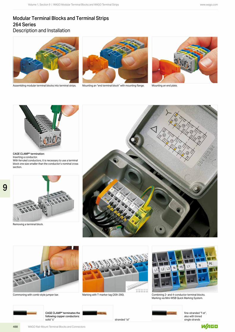
Assembling modular terminal blocks into terminal strips. Mounting an “end terminal block” with mounting flange. Mounting an end plate.
CAGE CLAMP® termination:Inserting a conductor.With ferruled conductors, it is necessary to use a terminal block one size smaller than the conductor’s nominal cross section.
Removing a terminal block.
Commoning with comb-style jumper bar. Marking with T-marker tag (209-290). Combining 2- and 4-conductor terminal blocks.Marking via Mini-WSB Quick Marking System.
CAGE CLAMP® terminates the following copper conductors:solid “s” stranded “st”
fine-stranded “f-st”, also with tinned single strands
9

489
www.wago.com
WAGO Rail-Mount Terminal Blocks and Connectors
Volume 1, Section 9 | WAGO Modular Terminal Blocks and WAGO Terminal Strips
fine-stranded, tip-bonded
fine-stranded, with ferrule (gastight crimped)
fine-stranded, with pin terminal (gastight crimped)
Mounting and securing a terminal strip directly to the plate via screw-type flanges.
Mounting a terminal strip with snap-in feet into holes. Mounting a terminal strip with snap-in feet onto the alumi-num mounting rail.
Ex e II terminal strip; with mounting flanges; for screw or similar mounting types; 3.2 mm mounting hole diameter
Ex e II terminal strip; with snap-in mounting feet; for 0.6 … 1.2 mm plate thickness; 3.5 mm mounting hole diameter
Testing via CAGE CLAMP® on the current bar (max. nomi-nal current: 6 A).CAGE CLAMP® clamps individual test contacts.The maximum test voltage is 400 V.
Testing by touch contact to the CAGE CLAMP® spring (limited to 0.5 A and 48 V test voltage) – test pins are not protected against accidental contact.
9
490
www.wago.com
WAGO Rail-Mount Terminal Blocks and Connectors
Volume 1, Section 9 | WAGO Modular Terminal Blocks and WAGO Terminal Strips
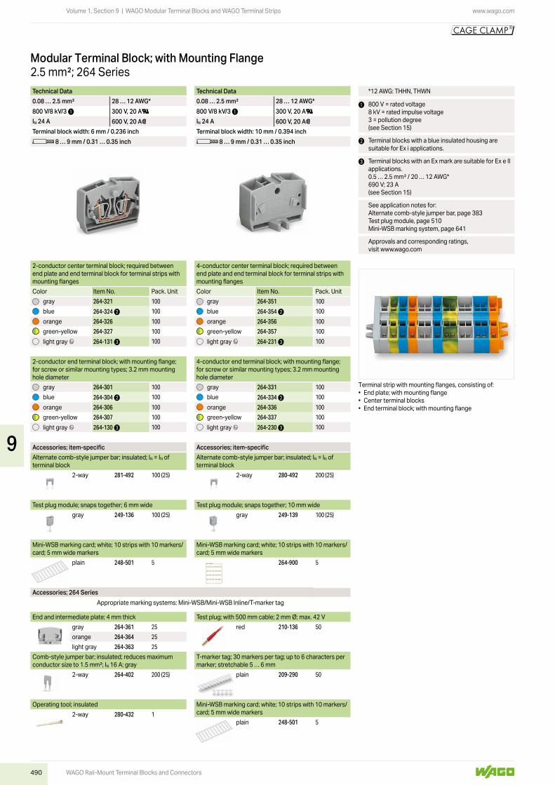
2.5 mm²; 264 SeriesModular Terminal Block; with Mounting Flange
2-conductor center terminal block; required between end plate and end terminal block for terminal strips with mounting flanges
4-conductor center terminal block; required between end plate and end terminal block for terminal strips with mounting flanges
Color Item No. Pack. Unit Color Item No. Pack. Unitgray 264-321 100 gray 264-351 100
blue 264-324 2 100 blue 264-354 2 100
orange 264-326 100 orange 264-356 100
green-yellow 264-327 100 green-yellow 264-357 100
light gray 4 264-131 3 100 light gray 4 264-231 3 100
2-conductor end terminal block; with mounting flange; for screw or similar mounting types; 3.2 mm mounting hole diameter
4-conductor end terminal block; with mounting flange; for screw or similar mounting types; 3.2 mm mounting hole diameter
gray 264-301 100 gray 264-331 100
blue 264-304 2 100 blue 264-334 2 100
orange 264-306 100 orange 264-336 100
green-yellow 264-307 100 green-yellow 264-337 100
light gray 4 264-130 3 100 light gray 4 264-230 3 100
Accessories; item-specific Accessories; item-specificAlternate comb-style jumper bar; insulated; IN = IN of terminal block
Alternate comb-style jumper bar; insulated; IN = IN of terminal block
2-way 281-492 100 (25) 2-way 280-492 200 (25)
Test plug module; snaps together; 6 mm wide Test plug module; snaps together; 10 mm widegray 249-136 100 (25) gray 249-139 100 (25)
Mini-WSB marking card; white; 10 strips with 10 markers/card; 5 mm wide markers
Mini-WSB marking card; white; 10 strips with 10 markers/card; 5 mm wide markers
plain 248-501 5 264-900 5
Accessories; 264 SeriesAppropriate marking systems: Mini-WSB/Mini-WSB Inline/T-marker tag
Technical Data Technical Data0.08 … 2.5 mm² 28 … 12 AWG* 0.08 … 2.5 mm² 28 … 12 AWG*800 V/8 kV/3 1 300 V, 20 AU 800 V/8 kV/3 1 300 V, 20 AUIN 24 A 600 V, 20 A2 IN 24 A 600 V, 20 A2Terminal block width: 6 mm / 0.236 inch Terminal block width: 10 mm / 0.394 inchL 8 … 9 mm / 0.31 … 0.35 inch L 8 … 9 mm / 0.31 … 0.35 inch
*12 AWG: THHN, THWN
1 800 V = rated voltage 8 kV = rated impulse voltage 3 = pollution degree(see Section 15)
2 Terminal blocks with a blue insulated housing are suitable for Ex i applications.
3 Terminal blocks with an Ex mark are suitable for Ex e II applications.0.5 … 2.5 mm² / 20 … 12 AWG*690 V; 23 A(see Section 15)
See application notes for:Alternate comb-style jumper bar, page 383Test plug module, page 510Mini-WSB marking system, page 641
Approvals and corresponding ratings, visit www.wago.com
End and intermediate plate; 4 mm thickgray 264-361 25
orange 264-364 25
light gray 264-363 25
Comb-style jumper bar; insulated; reduces maximum conductor size to 1.5 mm²; IN 16 A; gray
2-way 264-402 200 (25)
Operating tool; insulated2-way 280-432 1
Test plug; with 500 mm cable; 2 mm Ø; max. 42 Vred 210-136 50
T-marker tag; 30 markers per tag; up to 6 characters per marker; stretchable 5 … 6 mm
plain 209-290 50
Mini-WSB marking card; white; 10 strips with 10 markers/card; 5 mm wide markers
plain 248-501 5
Terminal strip with mounting flanges, consisting of:• End plate; with mounting flange• Center terminal blocks• End terminal block; with mounting flange
9
491
www.wago.com
WAGO Rail-Mount Terminal Blocks and Connectors
Volume 1, Section 9 | WAGO Modular Terminal Blocks and WAGO Terminal Strips
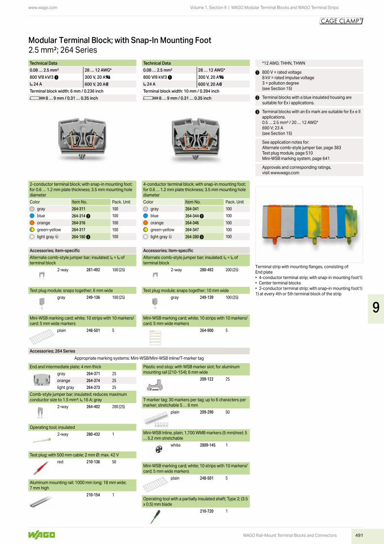
2.5 mm²; 264 SeriesModular Terminal Block; with Snap-In Mounting Foot
2-conductor terminal block; with snap-in mounting foot; for 0.6 … 1.2 mm plate thickness; 3.5 mm mounting hole diameter
4-conductor terminal block; with snap-in mounting foot; for 0.6 … 1.2 mm plate thickness; 3.5 mm mounting hole diameter
Color Item No. Pack. Unit Color Item No. Pack. Unitgray 264-311 100 gray 264-341 100
blue 264-314 2 100 blue 264-344 2 100
orange 264-316 100 orange 264-346 100
green-yellow 264-317 100 green-yellow 264-347 100
light gray 4 264-180 3 100 light gray 4 264-280 3 100
Accessories; item-specific Accessories; item-specificAlternate comb-style jumper bar; insulated; IN = IN of terminal block
Alternate comb-style jumper bar; insulated; IN = IN of terminal block
2-way 281-492 100 (25) 2-way 280-492 200 (25)
Test plug module; snaps together; 6 mm wide Test plug module; snaps together; 10 mm widegray 249-136 100 (25) gray 249-139 100 (25)
Mini-WSB marking card; white; 10 strips with 10 markers/card; 5 mm wide markers
Mini-WSB marking card; white; 10 strips with 10 markers/card; 5 mm wide markers
plain 248-501 5 264-900 5
Accessories; 264 SeriesAppropriate marking systems: Mini-WSB/Mini-WSB Inline/T-marker tag
Technical Data Technical Data0.08 … 2.5 mm² 28 … 12 AWG* 0.08 … 2.5 mm² 28 … 12 AWG*800 V/8 kV/3 1 300 V, 20 AU 800 V/8 kV/3 1 300 V, 20 AUIN 24 A 600 V, 20 A2 IN 24 A 600 V, 20 A2Terminal block width: 6 mm / 0.236 inch Terminal block width: 10 mm / 0.394 inchL 8 … 9 mm / 0.31 … 0.35 inch L 8 … 9 mm / 0.31 … 0.35 inch
*12 AWG: THHN, THWN
1 800 V = rated voltage 8 kV = rated impulse voltage 3 = pollution degree(see Section 15)
2 Terminal blocks with a blue insulated housing are suitable for Ex i applications.
3 Terminal blocks with an Ex mark are suitable for Ex e II applications.0.5 … 2.5 mm² / 20 … 12 AWG*690 V; 23 A(see Section 15)
See application notes for:Alternate comb-style jumper bar, page 383Test plug module, page 510Mini-WSB marking system, page 641
Approvals and corresponding ratings, visit www.wago.com
End and intermediate plate; 4 mm thickgray 264-371 25
orange 264-374 25
light gray 264-373 25
Comb-style jumper bar; insulated; reduces maximum conductor size to 1.5 mm²; IN 16 A; gray
2-way 264-402 200 (25)
Operating tool; insulated2-way 280-432 1
Test plug; with 500 mm cable; 2 mm Ø; max. 42 Vred 210-136 50
Aluminum mounting rail; 1000 mm long; 18 mm wide; 7 mm high
210-154 1
Plastic end stop; with WSB marker slot; for aluminum mounting rail (210-154); 6 mm wide
209-122 25
T-marker tag; 30 markers per tag; up to 6 characters per marker; stretchable 5 … 6 mm
plain 209-290 50
Mini-WSB Inline, plain; 1,700 WMB markers (5 mm)/reel; 5 … 5.2 mm stretchable
white 2009-145 1
Mini-WSB marking card; white; 10 strips with 10 markers/card; 5 mm wide markers
plain 248-501 5
Operating tool with a partially insulated shaft; Type 2; (3.5 x 0.5) mm blade
210-720 1
Terminal strip with mounting flanges, consisting of:End plate• 4-conductor terminal strip; with snap-in mounting foot1)• Center terminal blocks• 2-conductor terminal strip; with snap-in mounting foot1)1) at every 4th or 5th terminal block of the strip
9
492
www.wago.com
4,5
L10
4 3
5
32
22,1
15,8
4,5
L6
4 3
3
32
22,1
15,8
L6
4 3
3,6
6L1
L2
32
22,1 12
L10
4 3
3,6
6L1
L2
32
22,1 12
Modular terminal blocks and terminal strips with snap-in mounting feet
Modular terminal blocks and terminal strips with mounting flanges
L = (pole no. x pole width) + 7 mm
L = pole no. x pole width L1 = L + 9.6 mm L2 = L + 16 mm
WAGO Rail-Mount Terminal Blocks and Connectors
Volume 1, Section 9 | WAGO Modular Terminal Blocks and WAGO Terminal Strips
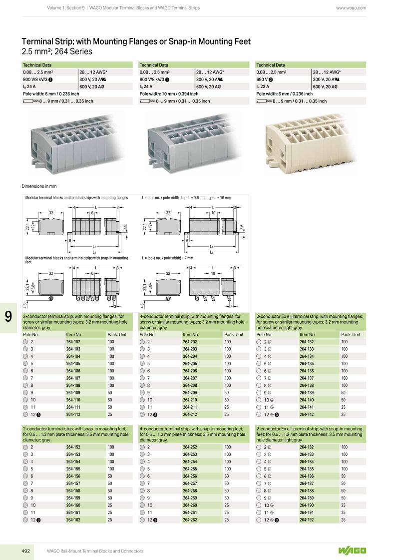
2.5 mm²; 264 SeriesTerminal Strip; with Mounting Flanges or Snap-in Mounting Feet
Technical Data Technical Data Technical Data Technical Data0.08 … 2.5 mm² 28 … 12 AWG* 0.08 … 2.5 mm² 28 … 12 AWG* 0.08 … 2.5 mm² 28 … 12 AWG* 0.08 … 2.5 mm² 28 … 12 AWG*800 V/8 kV/3 1 300 V, 20 AU 800 V/8 kV/3 1 300 V, 20 AU 690 V 2 300 V, 20 AU 690 V 2 300 V, 20 AUIN 24 A 600 V, 20 A2 IN 24 A 600 V, 20 A2 IN 23 A 600 V, 20 A2 IN 23 A 600 V, 20 A2Pole width: 6 mm / 0.236 inch Pole width: 10 mm / 0.394 inch Pole width: 6 mm / 0.236 inch Pole width: 10 mm / 0.394 inchL 8 … 9 mm / 0.31 … 0.35 inch L 8 … 9 mm / 0.31 … 0.35 inch L 8 … 9 mm / 0.31 … 0.35 inch L 8 … 9 mm / 0.31 … 0.35 inch
2-conductor terminal strip; with mounting flanges; for screw or similar mounting types; 3.2 mm mounting hole diameter; gray
4-conductor terminal strip; with mounting flanges; for screw or similar mounting types; 3.2 mm mounting hole diameter; gray
2-conductor Ex e II terminal strip; with mounting flanges; for screw or similar mounting types; 3.2 mm mounting hole diameter; light gray
4-conductor Ex e II terminal strip; with mounting flanges; for screw or similar mounting types; 3.2 mm mounting hole diameter; light gray
Pole No. Item No. Pack. Unit Pole No. Item No. Pack. Unit Pole No. Item No. Pack. Unit Pole No. Item No. Pack. Unit2 264-102 100 2 264-202 100 2 4 264-132 100 2 4 264-232 100
3 264-103 100 3 264-203 100 3 4 264-133 100 3 4 264-233 100
4 264-104 100 4 264-204 100 4 4 264-134 100 4 4 264-234 100
5 264-105 100 5 264-205 100 5 4 264-135 100 5 4 264-235 100
6 264-106 100 6 264-206 100 6 4 264-136 100 6 4 264-236 100
7 264-107 100 7 264-207 100 7 4 264-137 100 7 4 264-237 100
8 264-108 100 8 264-208 100 8 4 264-138 100 8 4 264-238 100
9 264-109 50 9 264-209 50 9 4 264-139 50 9 4 264-239 50
10 264-110 50 10 264-210 50 10 4 264-140 50 10 4 264-240 50
11 264-111 50 11 264-211 25 11 4 264-141 25 11 4 264-241 100
12 3 264-112 25 12 3 264-212 25 12 4 3 264-142 25 12 4 3 264-242 25
2-conductor terminal strip; with snap-in mounting feet; for 0.6 … 1.2 mm plate thickness; 3.5 mm mounting hole diameter; gray
4-conductor terminal strip; with snap-in mounting feet; for 0.6 … 1.2 mm plate thickness; 3.5 mm mounting hole diameter; gray
2-conductor Ex e II terminal strip; with snap-in mounting feet; for 0.6 … 1.2 mm plate thickness; 3.5 mm mounting hole diameter; light gray
4-conductor Ex e II terminal strip; with snap-in mounting feet; for 0.6 … 1.2 mm plate thickness; 3.5 mm mounting hole diameter; light gray
2 264-152 100 2 264-252 100 2 4 264-182 100 2 4 264-282 100
3 264-153 100 3 264-253 100 3 4 264-183 100 3 4 264-283 100
4 264-154 100 4 264-254 100 4 4 264-184 100 4 4 264-284 100
5 264-155 100 5 264-255 100 5 4 264-185 100 5 4 264-285 100
6 264-156 50 6 264-256 50 6 4 264-186 50 6 4 264-286 100
7 264-157 50 7 264-257 50 7 4 264-187 50 7 4 264-287 50
8 264-158 50 8 264-258 50 8 4 264-188 50 8 4 264-288 50
9 264-159 50 9 264-259 50 9 4 264-189 50 9 4 264-289 50
10 264-160 25 10 264-260 25 10 4 264-190 25 10 4 264-290 25
11 264-161 25 11 264-261 25 11 4 264-191 25 11 4 264-291 25
12 3 264-162 25 12 3 264-262 25 12 4 3 264-192 25 12 4 3 264-292 25
Dimensions in mm
9

493
www.wago.com
WAGO Rail-Mount Terminal Blocks and Connectors
Volume 1, Section 9 | WAGO Modular Terminal Blocks and WAGO Terminal Strips
*12 AWG: THHN, THWN
1 800 V = rated voltage 8 kV = rated impulse voltage 3 = pollution degree(see Section 15)
2 Suitable for Ex e II applications(see Section 15)
3 Longer strips and/or mixed-color assemblies are available upon request.
Approvals and corresponding ratings, visit www.wago.com
Technical Data Technical Data Technical Data Technical Data0.08 … 2.5 mm² 28 … 12 AWG* 0.08 … 2.5 mm² 28 … 12 AWG* 0.08 … 2.5 mm² 28 … 12 AWG* 0.08 … 2.5 mm² 28 … 12 AWG*800 V/8 kV/3 1 300 V, 20 AU 800 V/8 kV/3 1 300 V, 20 AU 690 V 2 300 V, 20 AU 690 V 2 300 V, 20 AUIN 24 A 600 V, 20 A2 IN 24 A 600 V, 20 A2 IN 23 A 600 V, 20 A2 IN 23 A 600 V, 20 A2Pole width: 6 mm / 0.236 inch Pole width: 10 mm / 0.394 inch Pole width: 6 mm / 0.236 inch Pole width: 10 mm / 0.394 inchL 8 … 9 mm / 0.31 … 0.35 inch L 8 … 9 mm / 0.31 … 0.35 inch L 8 … 9 mm / 0.31 … 0.35 inch L 8 … 9 mm / 0.31 … 0.35 inch
2-conductor terminal strip; with mounting flanges; for screw or similar mounting types; 3.2 mm mounting hole diameter; gray
4-conductor terminal strip; with mounting flanges; for screw or similar mounting types; 3.2 mm mounting hole diameter; gray
2-conductor Ex e II terminal strip; with mounting flanges; for screw or similar mounting types; 3.2 mm mounting hole diameter; light gray
4-conductor Ex e II terminal strip; with mounting flanges; for screw or similar mounting types; 3.2 mm mounting hole diameter; light gray
Pole No. Item No. Pack. Unit Pole No. Item No. Pack. Unit Pole No. Item No. Pack. Unit Pole No. Item No. Pack. Unit2 264-102 100 2 264-202 100 2 4 264-132 100 2 4 264-232 100
3 264-103 100 3 264-203 100 3 4 264-133 100 3 4 264-233 100
4 264-104 100 4 264-204 100 4 4 264-134 100 4 4 264-234 100
5 264-105 100 5 264-205 100 5 4 264-135 100 5 4 264-235 100
6 264-106 100 6 264-206 100 6 4 264-136 100 6 4 264-236 100
7 264-107 100 7 264-207 100 7 4 264-137 100 7 4 264-237 100
8 264-108 100 8 264-208 100 8 4 264-138 100 8 4 264-238 100
9 264-109 50 9 264-209 50 9 4 264-139 50 9 4 264-239 50
10 264-110 50 10 264-210 50 10 4 264-140 50 10 4 264-240 50
11 264-111 50 11 264-211 25 11 4 264-141 25 11 4 264-241 100
12 3 264-112 25 12 3 264-212 25 12 4 3 264-142 25 12 4 3 264-242 25
2-conductor terminal strip; with snap-in mounting feet; for 0.6 … 1.2 mm plate thickness; 3.5 mm mounting hole diameter; gray
4-conductor terminal strip; with snap-in mounting feet; for 0.6 … 1.2 mm plate thickness; 3.5 mm mounting hole diameter; gray
2-conductor Ex e II terminal strip; with snap-in mounting feet; for 0.6 … 1.2 mm plate thickness; 3.5 mm mounting hole diameter; light gray
4-conductor Ex e II terminal strip; with snap-in mounting feet; for 0.6 … 1.2 mm plate thickness; 3.5 mm mounting hole diameter; light gray
2 264-152 100 2 264-252 100 2 4 264-182 100 2 4 264-282 100
3 264-153 100 3 264-253 100 3 4 264-183 100 3 4 264-283 100
4 264-154 100 4 264-254 100 4 4 264-184 100 4 4 264-284 100
5 264-155 100 5 264-255 100 5 4 264-185 100 5 4 264-285 100
6 264-156 50 6 264-256 50 6 4 264-186 50 6 4 264-286 100
7 264-157 50 7 264-257 50 7 4 264-187 50 7 4 264-287 50
8 264-158 50 8 264-258 50 8 4 264-188 50 8 4 264-288 50
9 264-159 50 9 264-259 50 9 4 264-189 50 9 4 264-289 50
10 264-160 25 10 264-260 25 10 4 264-190 25 10 4 264-290 25
11 264-161 25 11 264-261 25 11 4 264-191 25 11 4 264-291 25
12 3 264-162 25 12 3 264-262 25 12 4 3 264-192 25 12 4 3 264-292 25
Snapping individual modules together to assemble a multi-pole test plug module.
Ex e II terminal strip; with snap-in mounting feet; for 0.6 … 1.2 mm plate thickness; 3.5 mm mounting hole diameter
Ex e II terminal strip; with mounting flanges; for screw or similar mounting types; 3.2 mm mounting hole diameter
Item no. suffixes for gray terminal strips with snap-in mounting feet:264-152 to 264-162264-252 to 264-262
blue …/000-006,Terminal strips with a blue insulated housing are suitable for Ex i applications.
Item no. suffixes for gray terminal strips with mounting flanges:264-102 to 264-112264-202 to 264-212
blue …/000-006,Terminal strips with a blue insulated housing are suitable for Ex i applications.
9

494
www.wago.com
WAGO Rail-Mount Terminal Blocks and Connectors
Volume 1, Section 9 | WAGO Modular Terminal Blocks and WAGO Terminal Strips
Description and Installation
Modular Terminal Blocks and Terminal Strips260 to 262 Series
Assembling modular terminal blocks into terminal strips. Mounting an end plate. Mounting and securing a terminal strip directly to the plate via screw-type flanges.
CAGE CLAMP® termination:Inserting a conductor.With ferruled conductors, it is necessary to use a terminal block one size smaller than the conductor’s nominal cross section.
CAGE CLAMP® termination:Inserting a conductor via push-button.
Terminal strip; with push-buttons on one side Terminal strip; with marker slot for Mini-WSB Quick Mark-ing System
Commoning with comb-style jumper bar.
CAGE CLAMP® terminates the following copper conductors:solid “s” stranded “st”
fine-stranded “f-st”, also with tinned single strands
9

495
www.wago.com
WAGO Rail-Mount Terminal Blocks and Connectors
Volume 1, Section 9 | WAGO Modular Terminal Blocks and WAGO Terminal Strips
fine-stranded, tip-bonded
fine-stranded, with ferrule (gastight crimped)
fine-stranded, with pin terminal (gastight crimped)
Mounting a terminal strip with snap-in feet into holes. Mounting a terminal strip with snap-in feet onto the alumi-num rail.
Mounting and securing a terminal strip directly to the plate via screw-type flanges.screwing a mounting foot (209-123)(distance between mounting feet: approx. 20 … 25 mm)
Marking with self-adhesive marking strips. Marking by direct printing (upon request). Terminal strip; with snap-in mounting feet; for DIN-35 rail
Terminal strip; with snap-in mounting feet; snapping a mounting foot (209-120)(distance between mounting feet: approx. 20 … 25 mm)
Terminal strip; with mounting flanges; for DIN-35 rail
9

496
www.wago.com
WAGO Rail-Mount Terminal Blocks and Connectors
Volume 1, Section 9 | WAGO Modular Terminal Blocks and WAGO Terminal Strips
1.5 mm²; 260 SeriesModular Terminal Block; with Mounting Flange or Snap-In Mounting Foot
2-conductor terminal block; with mounting flange; for screw or similar mounting types; 3.2 mm mounting hole diameter; with mounting foot (209-123) also for DIN-35 rail
4-conductor terminal block; with mounting flange; for screw or similar mounting types; 3.2 mm mounting hole diameter; with mounting foot (209-123) also for DIN-35 rail
Color Item No. Pack. Unit Color Item No. Pack. Unitgray 260-301 300 (50) gray 260-331 300 (50)
light gray 260-303 300 (50) light gray 260-333 300 (50)
blue 260-304 300 (50) blue 260-334 300 (50)
orange 260-306 300 (50) orange 260-336 300 (50)
green-yellow 260-307 300 (50) green-yellow 260-337 300 (50)
2-conductor terminal block; with snap-in mounting foot; for 0.6 … 1.2 mm plate thickness; 3.5 mm mounting hole diameter; also for aluminum rail (210-154) or with mount-ing foot (209-120) for DIN-35 rail
4-conductor terminal block; with snap-in mounting foot; for 0.6 … 1.2 mm plate thickness; 3.5 mm mounting hole diameter; also for aluminum rail (210-154) or with mount-ing foot (209-120) for DIN-35 rail
gray 260-311 300 (50) gray 260-341 300 (50)
light gray 260-313 300 (50) light gray 260-343 300 (50)
blue 260-314 300 (50) blue 260-344 300 (50)
orange 260-316 300 (50) orange 260-346 300 (50)
green-yellow 260-317 300 (50) green-yellow 260-347 300 (50)
Space-saving 2-conductor end terminal block; without protruding snap-in mounting foot; for terminal strips with snap-in mounting feet
Space-saving 4-conductor end terminal block; without protruding snap-in mounting foot; for terminal strips with snap-in mounting feet
gray 260-321 300 (50) gray 260-351 300 (50)
light gray 260-323 300 (50) light gray 260-353 300 (50)
blue 260-324 300 (50) blue 260-354 300 (50)
orange 260-326 300 (50) orange 260-356 300 (50)
green-yellow 260-327 300 (50) green-yellow 260-357 300 (50)
Accessories; item-specific Accessories; item-specificTest plug module; snaps together; 5 mm wide Test plug module; snaps together; 8 mm wide
gray 249-135 100 (25) gray 249-138 100 (25)
Test plug module; with locking latches; snaps together; 5 mm wide
Test plug module; with locking latches; snaps together; 8 mm wide
gray 260-404 100 (25) gray 260-405 100 (25)
Accessories; 260 SeriesMarking accessories, see Section 14
Technical Data Technical Data0.08 … 1.5 mm² (28 … 16 AWG)
28 … 16 AWG 0.08 … 1.5 mm² (28 … 16 AWG)
28 … 16 AWG
400 V/6 kV/3 1 300 V, 10 AU 400 V/6 kV/3 1 300 V, 10 AUIN 18 A 300 V, 15 A2 IN 18 A 300 V, 15 A2Terminal block width: 5 mm / 0.197 inch Terminal block width: 8 mm / 0.315 inchL 8 … 9 mm / 0.31 … 0.35 inch L 8 … 9 mm / 0.31 … 0.35 inch
1 400 V = rated voltage 6 kV = rated impulse voltage 3 = pollution degree(see Section 15)
See application notes for:Test plug module, page 510
Approvals and corresponding ratings, visit www.wago.com
Accessories; 260 SeriesMarking accessories, see Section 14
Test plug; with 500 mm cable; 2 mm Ø; max. 42 Vred 210-136 50
Aluminum mounting rail; 1000 mm long; 18 mm wide; 7 mm high
210-154 1
Plastic end stop; with WSB marker slot; for aluminum rail (210-154); 6 mm wide
209-122 25
Mounting foot; for DIN-35 rail; snaps onto terminal blocks with snap-in mounting foot; 6.4 mm wide
gray 209-120 25
Mounting screw; for mounting foot (209-120)209-119 500 (50)
Mounting foot with screw; for DIN-35 rail; can be screwed on terminal blocks with mounting flange; 6.4 mm wide
gray 209-123 25
Mounting adapter; for DIN-35 rail; can be used as end plate; 6.5 mm wide
gray 209-137 25
Operating tool with a partially insulated shaft; Type 2; (3.5 x 0.5) mm blade
210-720 1
End plate; with mounting flangegray 260-361 300 (50)
End plate; with snap-in mounting footgray 260-371 300 (50)
Comb-style jumper bar; insulated; reduces maximum conductor size to 1 mm²; IN 10 A; gray
2-way 260-402 25
Operating tool; insulated; for comb-style jumper bar2-way 209-132 1
9

497
www.wago.com
25,1
17,1
25,1
17,1
L5
2,5
5,42,8
L1
L2
L8
2,5
5,42,8
L1
L2
25,1
17,1
4,5
L0,4 3
5
2,2
5
4,5
L3
8
5,2
8
17,1
25,1
Modular terminal blocks and terminal strips with snap-in mounting feet
Modular terminal blocks and terminal strips with mounting flanges
L = (pole no. x pole width) + 3 mm • End terminal block
L = pole no. x pole width L1 = L + 8.1 mm L2 = L + 13.7 mm
WAGO Rail-Mount Terminal Blocks and Connectors
Volume 1, Section 9 | WAGO Modular Terminal Blocks and WAGO Terminal Strips
Technical Data Technical Data0.08 … 1.5 mm² (28 … 16 AWG)
28 … 16 AWG 0.08 … 1.5 mm² (28 … 16 AWG)
28 … 16 AWG
400 V/6 kV/3 1 300 V, 10 AU 400 V/6 kV/3 1 300 V, 10 AUIN 18 A 300 V, 15 A2 IN 18 A 300 V, 15 A2Pole width: 5 mm / 0.197 inch Pole width: 8 mm / 0.315 inchL 8 … 9 mm / 0.31 … 0.35 inch L 8 … 9 mm / 0.31 … 0.35 inch
1 400 V = rated voltage 6 kV = rated impulse voltage 3 = pollution degree(see Section 15)
2 Longer strips and/or mixed-color assemblies are available upon request.
Approvals and corresponding ratings, visit www.wago.com
Terminal strip; with mounting flanges; for screw or similar mounting types; 3.2 mm mounting hole diameter (with 209-123 Mounting Foot for DIN-35 rail)
Terminal strip; with snap-in mounting feet; for 0.6 … 1.2 mm plate thickness; 3.5 mm mounting hole diam-eter (also for 210-154 Aluminum Rail or with 209-120 Mounting Foot for DIN-35 rail)
1.5 mm²; 260 SeriesTerminal Strip; with Mounting Flanges or Snap-in Mounting Feet
2-conductor terminal strip; with mounting flanges; for screw or similar mounting types; 3.2 mm mounting hole diameter; with mounting foot (209-123) also for DIN-35 rail; gray
4-conductor terminal strip; with mounting flanges; for screw or similar mounting types; 3.2 mm mounting hole diameter; with mounting foot (209-123) also for DIN-35 rail; gray
Pole No. Item No. Pack. Unit Pole No. Item No. Pack. Unit2 260-102 100 2 260-202 100
3 260-103 100 3 260-203 100
4 260-104 100 4 260-204 100
5 260-105 100 5 260-205 100
6 260-106 100 6 260-206 100
7 260-107 100 7 260-207 100
8 260-108 100 8 260-208 100
9 260-109 50 9 260-209 50
10 260-110 50 10 260-210 50
11 260-111 50 11 260-211 25
12 2 260-112 25 12 2 260-212 25
2-conductor terminal strip; with snap-in mounting feet; for 0.6 … 1.2 mm plate thickness; 3.5 mm mounting hole diameter; also for aluminum rail (210-154) or with mount-ing foot (209-120) for DIN-35 rail; gray
4-conductor terminal strip; with snap-in mounting feet; for 0.6 … 1.2 mm plate thickness; 3.5 mm mounting hole diameter; also for aluminum rail (210-154) or with mount-ing foot (209-120) for DIN-35 rail; gray
2 260-152 100 2 260-252 100
3 260-153 100 3 260-253 100
4 260-154 100 4 260-254 100
5 260-155 100 5 260-255 100
6 260-156 50 6 260-256 50
7 260-157 50 7 260-257 50
8 260-158 50 8 260-258 50
9 260-159 50 9 260-259 50
10 260-160 25 10 260-260 25
11 260-161 25 11 260-261 25
12 2 260-162 25 12 2 260-262 25
Dimensions in mm
9

498
www.wago.com
WAGO Rail-Mount Terminal Blocks and Connectors
Volume 1, Section 9 | WAGO Modular Terminal Blocks and WAGO Terminal Strips
2.5 mm²; 261 SeriesModular Terminal Block; with Mounting Flange or Snap-In Mounting Foot
2-conductor terminal block; with mounting flange; for screw or similar mounting types; 3.2 mm mounting hole diameter; with mounting foot (209-123) also for DIN-35 rail
4-conductor terminal block; with mounting flange; for screw or similar mounting types; 3.2 mm mounting hole diameter; with mounting foot (209-123) also for DIN-35 rail
Color Item No. Pack. Unit Color Item No. Pack. Unitgray 261-301 200 (50) gray 261-331 200 (50)
light gray 261-303 200 (50) light gray 261-333 200 (50)
blue 261-304 2 200 (50) blue 261-334 2 200 (50)
orange 261-306 200 (50) orange 261-336 200 (50)
green-yellow 261-307 200 (50) green-yellow 261-337 200 (50)
2-conductor terminal block; with snap-in mounting foot; for 0.6 … 1.2 mm plate thickness; 3.5 mm mounting hole diameter; also for aluminum rail (210-154) or with mount-ing foot (209-120) for DIN-35 rail
4-conductor terminal block; with snap-in mounting foot; for 0.6 … 1.2 mm plate thickness; 3.5 mm mounting hole diameter; also for aluminum rail (210-154) or with mount-ing foot (209-120) for DIN-35 rail
gray 261-311 200 (50) gray 261-341 200 (50)
light gray 261-313 200 (50) light gray 261-343 200 (50)
blue 261-314 2 200 (50) blue 261-344 2 200 (50)
orange 261-316 200 (50) orange 261-346 200 (50)
green-yellow 261-317 200 (50) green-yellow 261-347 200 (50)
Space-saving 2-conductor end terminal block; without protruding snap-in mounting foot; for terminal strips with snap-in mounting feet
Space-saving 4-conductor end terminal block; without protruding snap-in mounting foot; for terminal strips with snap-in mounting feet
gray 261-321 200 (50) gray 261-351 200 (50)
light gray 261-323 200 (50) light gray 261-353 200 (50)
blue 261-324 2 200 (50) blue 261-354 2 200 (50)
orange 261-326 200 (50) orange 261-356 200 (50)
green-yellow 261-327 200 (50) green-yellow 261-357 200 (50)
Accessories; item-specific Accessories; item-specificTest plug module; snaps together; 6 mm wide Test plug module; snaps together; 10 mm wide
gray 249-136 100 (25) gray 249-139 100 (25)
Test plug module; with locking latches; snaps together; 6 mm wide
Test plug module; with locking latches; snaps together; 10 mm wide
gray 261-404 100 (25) gray 261-405 100 (25)
Accessories; 261 SeriesMarking accessories, see Section 14
Technical Data Technical Data0.08 … 2.5 mm² 28 … 14 AWG 0.08 … 2.5 mm² 28 … 14 AWG500 V/6 kV/3 1 300 V, 15 AU 500 V/6 kV/3 1 300 V, 15 AUIN 24 A 300 V, 20 A2 IN 24 A 300 V, 20 A2Terminal block width: 6 mm / 0.236 inch Terminal block width: 10 mm / 0.394 inchL 8 … 9 mm / 0.31 … 0.35 inch L 8 … 9 mm / 0.31 … 0.35 inch
1 500 V = rated voltage 6 kV = rated impulse voltage 3 = pollution degree(see Section 15)
2 Terminal blocks with a blue insulated housing are suitable for Ex i applications.
See application notes for:Test plug module, page 510
Approvals and corresponding ratings, visit www.wago.com
Accessories; 261 SeriesMarking accessories, see Section 14
Test plug; with 500 mm cable; 2 mm Ø; max. 42 Vred 210-136 50
Aluminum mounting rail; 1000 mm long; 18 mm wide; 7 mm high
210-154 1
Plastic end stop; with WSB marker slot; for aluminum rail (210-154); 6 mm wide
209-122 25
Mounting foot; for DIN-35 rail; snaps onto terminal blocks with snap-in mounting foot; 6.4 mm wide
gray 209-120 25
Mounting screw; for mounting foot (209-120)209-119 500 (50)
Mounting foot with screw; for DIN-35 rail; can be screwed on terminal blocks with mounting flange; 6.4 mm wide
gray 209-123 25
Mounting adapter; for DIN-35 rail; can be used as end plate; 6.5 mm wide
gray 209-137 25
Operating tool with a partially insulated shaft; Type 2; (3.5 x 0.5) mm blade
210-720 1
End plate; with mounting flangegray 261-361 300 (50)
End plate; with snap-in mounting footgray 261-371 300 (50)
Comb-style jumper bar; insulated; reduces maximum conductor size to 1.5 mm²; IN 16 A; gray
2-way 261-402 25
Operating tool; insulated; for comb-style jumper bar2-way 209-132 1
9
499
www.wago.com
4,5
L10
7,2
10
L10 2,5
5,82,8
L1L2
4,5
L 3 36
3,2
6
L6 2,5
5,82,8
L1L2
28,1
18,1
28,1
18,1
28,1
18,1
28,1
18,1
Modular terminal blocks and terminal strips with snap-in mounting feet
Modular terminal blocks and terminal strips with mounting flanges
L = (pole no. x pole width) + 3 mm • End terminal block
L = pole no. x pole width L1 = L + 8.1 mm L2 = L + 14.1 mm
WAGO Rail-Mount Terminal Blocks and Connectors
Volume 1, Section 9 | WAGO Modular Terminal Blocks and WAGO Terminal Strips
Technical Data Technical Data0.08 … 2.5 mm² 28 … 14 AWG 0.08 … 2.5 mm² 28 … 14 AWG500 V/6 kV/3 1 300 V, 15 AU 500 V/6 kV/3 1 300 V, 15 AUIN 24 A 300 V, 20 A2 IN 24 A 300 V, 20 A2Pole width: 6 mm / 0.236 inch Pole width: 10 mm / 0.394 inchL 8 … 9 mm / 0.31 … 0.35 inch L 8 … 9 mm / 0.31 … 0.35 inch
1 500 V = rated voltage 6 kV = rated impulse voltage 3 = pollution degree(see Section 15)
2 Terminal strips with a blue insulated housing are suitable for Ex i applications.Item no. suffixes …/000-006 (upon request)
3 Longer strips and/or mixed-color assemblies are available upon request.
Approvals and corresponding ratings, visit www.wago.com
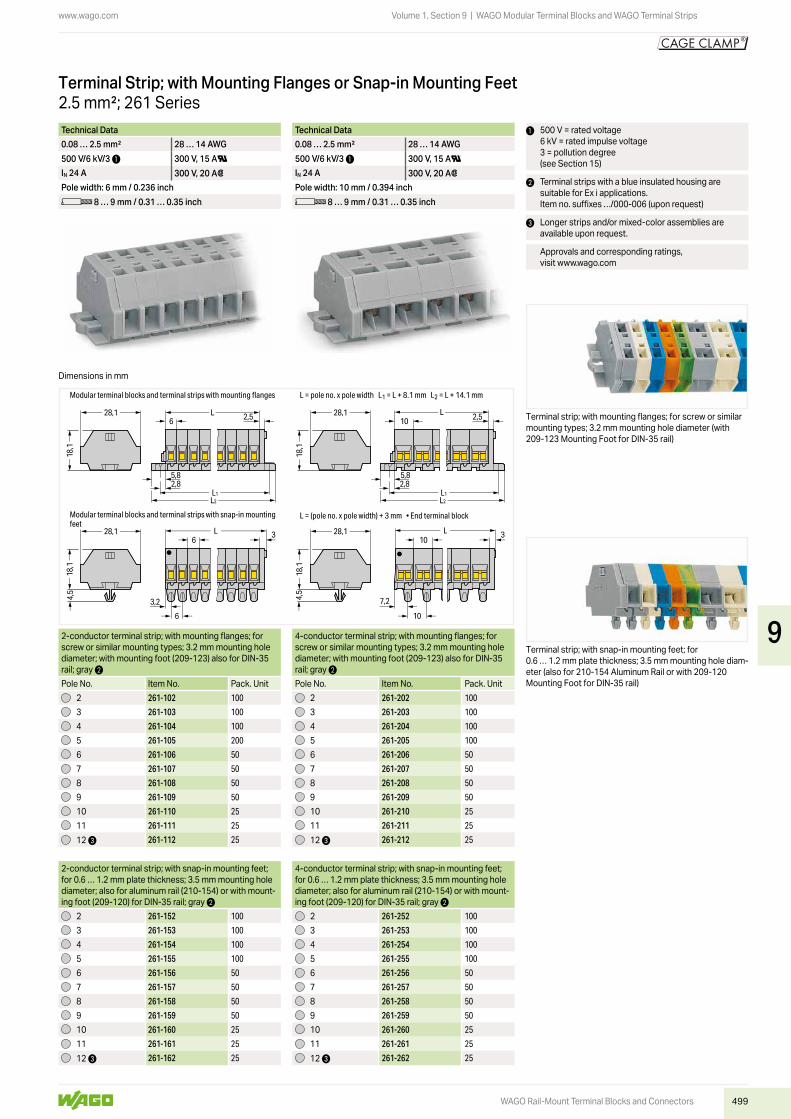
Terminal strip; with mounting flanges; for screw or similar mounting types; 3.2 mm mounting hole diameter (with 209-123 Mounting Foot for DIN-35 rail)
Terminal strip; with snap-in mounting feet; for 0.6 … 1.2 mm plate thickness; 3.5 mm mounting hole diam-eter (also for 210-154 Aluminum Rail or with 209-120 Mounting Foot for DIN-35 rail)
2.5 mm²; 261 SeriesTerminal Strip; with Mounting Flanges or Snap-in Mounting Feet
2-conductor terminal strip; with mounting flanges; for screw or similar mounting types; 3.2 mm mounting hole diameter; with mounting foot (209-123) also for DIN-35 rail; gray 2
4-conductor terminal strip; with mounting flanges; for screw or similar mounting types; 3.2 mm mounting hole diameter; with mounting foot (209-123) also for DIN-35 rail; gray 2
Pole No. Item No. Pack. Unit Pole No. Item No. Pack. Unit2 261-102 100 2 261-202 100
3 261-103 100 3 261-203 100
4 261-104 100 4 261-204 100
5 261-105 200 5 261-205 100
6 261-106 50 6 261-206 50
7 261-107 50 7 261-207 50
8 261-108 50 8 261-208 50
9 261-109 50 9 261-209 50
10 261-110 25 10 261-210 25
11 261-111 25 11 261-211 25
12 3 261-112 25 12 3 261-212 25
2-conductor terminal strip; with snap-in mounting feet; for 0.6 … 1.2 mm plate thickness; 3.5 mm mounting hole diameter; also for aluminum rail (210-154) or with mount-ing foot (209-120) for DIN-35 rail; gray 2
4-conductor terminal strip; with snap-in mounting feet; for 0.6 … 1.2 mm plate thickness; 3.5 mm mounting hole diameter; also for aluminum rail (210-154) or with mount-ing foot (209-120) for DIN-35 rail; gray 2
2 261-152 100 2 261-252 100
3 261-153 100 3 261-253 100
4 261-154 100 4 261-254 100
5 261-155 100 5 261-255 100
6 261-156 50 6 261-256 50
7 261-157 50 7 261-257 50
8 261-158 50 8 261-258 50
9 261-159 50 9 261-259 50
10 261-160 25 10 261-260 25
11 261-161 25 11 261-261 25
12 3 261-162 25 12 3 261-262 25
Dimensions in mm
9

500
www.wago.com
WAGO Rail-Mount Terminal Blocks and Connectors
Volume 1, Section 9 | WAGO Modular Terminal Blocks and WAGO Terminal Strips
2.5 mm²; 261 Series
Modular Terminal Block; with Push-Buttons on One Side; with Mounting Flange or Snap-In Mounting Foot
2-conductor terminal block; with push-button on one side; with mounting flange; for screw or similar mounting types; 3.2 mm mounting hole diameter; with mounting foot (209-123) also for DIN-35 rail
4-conductor terminal block; with push-button on one side; with mounting flange; for screw or similar mounting types; 3.2 mm mounting hole diameter; with mounting foot (209-123) also for DIN-35 rail
Color Item No. Pack. Unit Color Item No. Pack. Unitgray 261-301/331-000 200 (50) gray 261-331/332-000 200 (50)
light gray 261-303/331-000 200 (50) light gray 261-333/332-000 200 (50)
blue 261-304/331-000 2 200 (50) blue 261-334/332-000 2 200 (50)
orange 261-306/331-000 200 (50) orange 261-336/332-000 200 (50)
green-yellow 261-307/331-000 200 (50) green-yellow 261-337/332-000 200 (50)
2-conductor terminal block; with push-button on one side; with snap-in mounting foot; for 0.6 … 1.2 mm plate thickness; 3.5 mm mounting hole diameter; also for aluminum rail (210-154) or with mounting foot (209-120) for DIN-35 rail
4-conductor terminal block; with push-button on one side; with snap-in mounting foot; for 0.6 … 1.2 mm plate thickness; 3.5 mm mounting hole diameter; also for aluminum rail (210-154) or with mounting foot (209-120) for DIN-35 rail
gray 261-311/331-000 200 (50) gray 261-341/332-000 200 (50)
light gray 261-313/331-000 200 (50) light gray 261-343/332-000 200 (50)
blue 261-314/331-000 2 200 (50) blue 261-344/332-000 2 200 (50)
orange 261-316/331-000 200 (50) orange 261-346/332-000 200 (50)
green-yellow 261-317/331-000 200 (50) green-yellow 261-347/332-000 200 (50)
Space-saving 2-conductor end terminal block; with push-button on one side; without protruding snap-in mounting foot; for terminal strips with snap-in mounting feet
Space-saving 4-conductor end terminal block; with push-button on one side; without protruding snap-in mounting foot; for terminal strips with snap-in mounting feet
gray 261-321/331-000 200 (50) gray 261-351/332-000 200 (50)
light gray 261-323/331-000 200 (50) light gray 261-353/332-000 200 (50)
blue 261-324/331-000 2 200 (50) blue 261-354/332-000 2 200 (50)
orange 261-326/331-000 200 (50) orange 261-356/332-000 200 (50)
green-yellow 261-327/331-000 200 (50) green-yellow 261-357/332-000 200 (50)
Accessories; 261 SeriesMarking accessories, see Section 14
Technical Data Technical Data0.08 … 2.5 mm² 28 … 14 AWG 0.08 … 2.5 mm² 28 … 14 AWG500 V/6 kV/3 1 300 V, 15 AU 500 V/6 kV/3 1 300 V, 15 AUIN 24 A 300 V, 20 A2 IN 24 A 300 V, 20 A2Terminal block width: 6 mm / 0.236 inch Terminal block width: 10 mm / 0.394 inchL 8 … 9 mm / 0.31 … 0.35 inch L 8 … 9 mm / 0.31 … 0.35 inch
1 500 V = rated voltage 6 kV = rated impulse voltage 3 = pollution degree(see Section 15)
2 Terminal blocks with a blue insulated housing are suitable for Ex i applications.
Approvals and corresponding ratings, visit www.wago.com
Accessories; 261 SeriesMarking accessories, see Section 14
Mounting foot; for DIN-35 rail; snaps onto terminal blocks with snap-in mounting foot; 6.4 mm wide
gray 209-120 25
Mounting screw; for mounting foot (209-120)209-119 500 (50)
Mounting foot with screw; for DIN-35 rail; can be screwed on terminal blocks with mounting flange; 6.4 mm wide
gray 209-123 25
Mounting adapter; for DIN-35 rail; can be used as end plate; 6.5 mm wide
gray 209-137 25
Operating tool with a partially insulated shaft; Type 2; (3.5 x 0.5) mm blade
210-720 1
Test plug; with 500 mm cable; 2 mm Ø; max. 42 Vred 210-136 50
Aluminum mounting rail; 1000 mm long; 18 mm wide; 7 mm high
210-154 1
Plastic end stop; with WSB marker slot; for aluminum rail (210-154); 6 mm wide
209-122 25
End plate; with mounting flangegray 261-361 300 (50)
End plate; with snap-in mounting footgray 261-371 300 (50)
Comb-style jumper bar; insulated; reduces maximum conductor size to 1.5 mm²; IN 16 A; gray
2-way 261-402 25
Operating tool; insulated; for comb-style jumper bar2-way 209-132 1
9

501
www.wago.com
4,5
5,2
L10
7,2
10
5,2
L10 2,5
5,82,8
L1L2
4,5
5,2
L 3 36
3,2
6
L6 2,5
5,82,8
L1L2
28,1
18,1
28,1
18,1
28,1
18,1
28,1
18,1
5,2
Modular terminal blocks and terminal strips with snap-in mounting feet
Modular terminal blocks and terminal strips with mounting flanges
L = (pole no. x pole width) + 3 mm • End terminal block
L = pole no. x pole width L1 = L + 8.1 mm L2 = L + 14.1 mm
WAGO Rail-Mount Terminal Blocks and Connectors
Volume 1, Section 9 | WAGO Modular Terminal Blocks and WAGO Terminal Strips
Technical Data Technical Data0.08 … 2.5 mm² 28 … 14 AWG 0.08 … 2.5 mm² 28 … 14 AWG500 V/6 kV/3 1 500 V/6 kV/3 1IN 24 A IN 24 APole width: 6 mm / 0.236 inch Pole width: 10 mm / 0.394 inchL 8 … 9 mm / 0.31 … 0.35 inch L 8 … 9 mm / 0.31 … 0.35 inch
1 500 V = rated voltage 6 kV = rated impulse voltage 3 = pollution degree(see Section 15)
2 Terminal strips with a blue insulated housing are suitable for Ex i applications.Item no. suffixes …/000-006 (upon request)
3 Longer strips and/or mixed-color assemblies are available upon request.
Approvals and corresponding ratings, visit www.wago.com
Terminal strip; with mounting flanges; for screw or similar mounting types; 3.2 mm mounting hole diameter (with 209-123 Mounting Foot for DIN-35 rail)
Terminal strip; with snap-in mounting feet; for 0.6 … 1.2 mm plate thickness; 3.5 mm mounting hole diam-eter (also for 210-154 Aluminum Rail or with 209-120 Mounting Foot for DIN-35 rail)
2.5 mm²; 261 SeriesTerminal Strip; with Push-Buttons on One Side; with Mounting Flanges or Snap-in Mounting Feet
2-conductor terminal strip; with push-buttons on one side; with mounting flanges; for screw or similar mount-ing types; 3.2 mm mounting hole diameter; with mounting foot (209-123) also for DIN-35 rail; gray 2
4-conductor terminal strip; with push-buttons on one side; with mounting flanges; for screw or similar mount-ing types; 3.2 mm mounting hole diameter; with mounting foot (209-123) also for DIN-35 rail; gray 2
Pole No. Item No. Pack. Unit Pole No. Item No. Pack. Unit2 261-102/331-000 100 2 261-202/332-000 100
3 261-103/331-000 100 3 261-203/332-000 100
4 261-104/331-000 100 4 261-204/332-000 100
5 261-105/331-000 200 5 261-205/332-000 100
6 261-106/331-000 50 6 261-206/332-000 50
7 261-107/331-000 50 7 261-207/332-000 50
8 261-108/331-000 50 8 261-208/332-000 50
9 261-109/331-000 50 9 261-209/332-000 50
10 261-110/331-000 25 10 261-210/332-000 50
11 261-111/331-000 25 11 261-211/332-000 25
12 3 261-112/331-000 25 12 3 261-212/332-000 50
2-conductor terminal strip; with push-buttons on one side; with snap-in mounting feet; for 0.6 … 1.2 mm plate thickness; 3.5 mm mounting hole diameter; also for aluminum rail (210-154) or with mounting foot (209-120) for DIN-35 rail; gray 2
4-conductor terminal strip; with push-buttons on one side; with snap-in mounting feet; for 0.6 … 1.2 mm plate thickness; 3.5 mm mounting hole diameter; also for aluminum rail (210-154) or with mounting foot (209-120) for DIN-35 rail; gray 2
2 261-152/331-000 100 2 261-252/332-000 100
3 261-153/331-000 100 3 261-253/332-000 100
4 261-154/331-000 100 4 261-254/332-000 100
5 261-155/331-000 100 5 261-255/332-000 100
6 261-156/331-000 50 6 261-256/332-000 50
7 261-157/331-000 50 7 261-257/332-000 50
8 261-158/331-000 50 8 261-258/332-000 50
9 261-159/331-000 50 9 261-259/332-000 50
10 261-160/331-000 25 10 261-260/332-000 25
11 261-161/331-000 25 11 261-261/332-000 100
12 3 261-162/331-000 25 12 3 261-262/332-000 25
Dimensions in mm
9
502
www.wago.com
WAGO Rail-Mount Terminal Blocks and Connectors
Volume 1, Section 9 | WAGO Modular Terminal Blocks and WAGO Terminal Strips
2.5 mm²; 261 Series
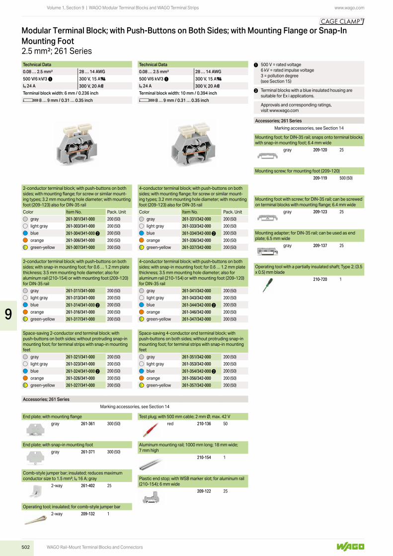
Modular Terminal Block; with Push-Buttons on Both Sides; with Mounting Flange or Snap-In Mounting Foot
2-conductor terminal block; with push-buttons on both sides; with mounting flange; for screw or similar mount-ing types; 3.2 mm mounting hole diameter; with mounting foot (209-123) also for DIN-35 rail
4-conductor terminal block; with push-buttons on both sides; with mounting flange; for screw or similar mount-ing types; 3.2 mm mounting hole diameter; with mounting foot (209-123) also for DIN-35 rail
Color Item No. Pack. Unit Color Item No. Pack. Unitgray 261-301/341-000 200 (50) gray 261-331/342-000 200 (50)
light gray 261-303/341-000 200 (50) light gray 261-333/342-000 200 (50)
blue 261-304/341-000 2 200 (50) blue 261-334/342-000 2 200 (50)
orange 261-306/341-000 200 (50) orange 261-336/342-000 200 (50)
green-yellow 261-307/341-000 200 (50) green-yellow 261-337/342-000 200 (50)
2-conductor terminal block; with push-buttons on both sides; with snap-in mounting foot; for 0.6 … 1.2 mm plate thickness; 3.5 mm mounting hole diameter; also for aluminum rail (210-154) or with mounting foot (209-120) for DIN-35 rail
4-conductor terminal block; with push-buttons on both sides; with snap-in mounting foot; for 0.6 … 1.2 mm plate thickness; 3.5 mm mounting hole diameter; also for aluminum rail (210-154) or with mounting foot (209-120) for DIN-35 rail
gray 261-311/341-000 200 (50) gray 261-341/342-000 200 (50)
light gray 261-313/341-000 200 (50) light gray 261-343/342-000 200 (50)
blue 261-314/341-000 2 200 (50) blue 261-344/342-000 2 200 (50)
orange 261-316/341-000 200 (50) orange 261-346/342-000 200 (50)
green-yellow 261-317/341-000 200 (50) green-yellow 261-347/342-000 200 (50)
Space-saving 2-conductor end terminal block; with push-buttons on both sides; without protruding snap-in mounting foot; for terminal strips with snap-in mounting feet
Space-saving 4-conductor end terminal block; with push-buttons on both sides; without protruding snap-in mounting foot; for terminal strips with snap-in mounting feet
gray 261-321/341-000 200 (50) gray 261-351/342-000 200 (50)
light gray 261-323/341-000 200 (50) light gray 261-353/342-000 200 (50)
blue 261-324/341-000 2 200 (50) blue 261-354/342-000 2 200 (50)
orange 261-326/341-000 200 (50) orange 261-356/342-000 200 (50)
green-yellow 261-327/341-000 200 (50) green-yellow 261-357/342-000 200 (50)
Accessories; 261 SeriesMarking accessories, see Section 14
Technical Data Technical Data0.08 … 2.5 mm² 28 … 14 AWG 0.08 … 2.5 mm² 28 … 14 AWG500 V/6 kV/3 1 300 V, 15 AU 500 V/6 kV/3 1 300 V, 15 AUIN 24 A 300 V, 20 A2 IN 24 A 300 V, 20 A2Terminal block width: 6 mm / 0.236 inch Terminal block width: 10 mm / 0.394 inchL 8 … 9 mm / 0.31 … 0.35 inch L 8 … 9 mm / 0.31 … 0.35 inch
1 500 V = rated voltage 6 kV = rated impulse voltage 3 = pollution degree(see Section 15)
2 Terminal blocks with a blue insulated housing are suitable for Ex i applications.
Approvals and corresponding ratings, visit www.wago.com
Accessories; 261 SeriesMarking accessories, see Section 14
Mounting foot; for DIN-35 rail; snaps onto terminal blocks with snap-in mounting foot; 6.4 mm wide
gray 209-120 25
Mounting screw; for mounting foot (209-120)209-119 500 (50)
Mounting foot with screw; for DIN-35 rail; can be screwed on terminal blocks with mounting flange; 6.4 mm wide
gray 209-123 25
Mounting adapter; for DIN-35 rail; can be used as end plate; 6.5 mm wide
gray 209-137 25
Operating tool with a partially insulated shaft; Type 2; (3.5 x 0.5) mm blade
210-720 1
Test plug; with 500 mm cable; 2 mm Ø; max. 42 Vred 210-136 50
Aluminum mounting rail; 1000 mm long; 18 mm wide; 7 mm high
210-154 1
Plastic end stop; with WSB marker slot; for aluminum rail (210-154); 6 mm wide
209-122 25
End plate; with mounting flangegray 261-361 300 (50)
End plate; with snap-in mounting footgray 261-371 300 (50)
Comb-style jumper bar; insulated; reduces maximum conductor size to 1.5 mm²; IN 16 A; gray
2-way 261-402 25
Operating tool; insulated; for comb-style jumper bar2-way 209-132 1
9
503
www.wago.com
4,5
5,2
L10
7,2
10
5,2
L10 2,5
5,82,8
L1L2
4,5
5,2
L 3 36
3,2
6
L6 2,5
5,82,8
L1L2
28,1
18,1
28,1
18,1
28,1
18,1
28,1
18,1
5,2
Modular terminal blocks and terminal strips with snap-in mounting feet
Modular terminal blocks and terminal strips with mounting flanges
L = (pole no. x pole width) + 3 mm • End terminal block
L = pole no. x pole width L1 = L + 8.1 mm L2 = L + 14.1 mm
WAGO Rail-Mount Terminal Blocks and Connectors
Volume 1, Section 9 | WAGO Modular Terminal Blocks and WAGO Terminal Strips
Technical Data Technical Data0.08 … 2.5 mm² 28 … 14 AWG 0.08 … 2.5 mm² 28 … 14 AWG500 V/6 kV/3 1 500 V/6 kV/3 1IN 24 A IN 24 APole width: 6 mm / 0.236 inch Pole width: 10 mm / 0.394 inchL 8 … 9 mm / 0.31 … 0.35 inch L 8 … 9 mm / 0.31 … 0.35 inch
1 500 V = rated voltage 6 kV = rated impulse voltage 3 = pollution degree(see Section 15)
2 Terminal strips with a blue insulated housing are suitable for Ex i applications.Item no. suffixes …/000-006 (upon request)
3 Longer strips and/or mixed-color assemblies are available upon request.
Approvals and corresponding ratings, visit www.wago.com
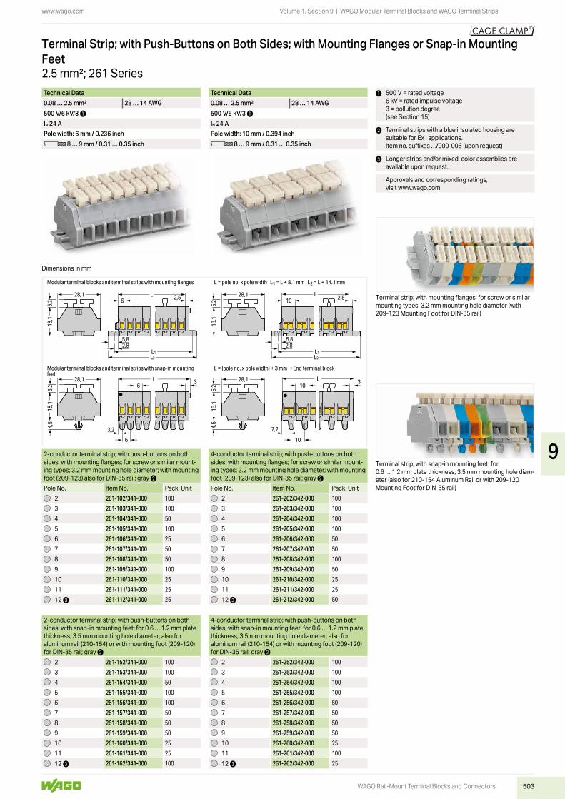
Terminal strip; with mounting flanges; for screw or similar mounting types; 3.2 mm mounting hole diameter (with 209-123 Mounting Foot for DIN-35 rail)
Terminal strip; with snap-in mounting feet; for 0.6 … 1.2 mm plate thickness; 3.5 mm mounting hole diam-eter (also for 210-154 Aluminum Rail or with 209-120 Mounting Foot for DIN-35 rail)
2.5 mm²; 261 Series
Terminal Strip; with Push-Buttons on Both Sides; with Mounting Flanges or Snap-in Mounting Feet
2-conductor terminal strip; with push-buttons on both sides; with mounting flanges; for screw or similar mount-ing types; 3.2 mm mounting hole diameter; with mounting foot (209-123) also for DIN-35 rail; gray 2
4-conductor terminal strip; with push-buttons on both sides; with mounting flanges; for screw or similar mount-ing types; 3.2 mm mounting hole diameter; with mounting foot (209-123) also for DIN-35 rail; gray 2
Pole No. Item No. Pack. Unit Pole No. Item No. Pack. Unit2 261-102/341-000 100 2 261-202/342-000 100
3 261-103/341-000 100 3 261-203/342-000 100
4 261-104/341-000 50 4 261-204/342-000 100
5 261-105/341-000 100 5 261-205/342-000 100
6 261-106/341-000 25 6 261-206/342-000 50
7 261-107/341-000 50 7 261-207/342-000 50
8 261-108/341-000 50 8 261-208/342-000 100
9 261-109/341-000 100 9 261-209/342-000 50
10 261-110/341-000 25 10 261-210/342-000 25
11 261-111/341-000 25 11 261-211/342-000 25
12 3 261-112/341-000 25 12 3 261-212/342-000 50
2-conductor terminal strip; with push-buttons on both sides; with snap-in mounting feet; for 0.6 … 1.2 mm plate thickness; 3.5 mm mounting hole diameter; also for aluminum rail (210-154) or with mounting foot (209-120) for DIN-35 rail; gray 2
4-conductor terminal strip; with push-buttons on both sides; with snap-in mounting feet; for 0.6 … 1.2 mm plate thickness; 3.5 mm mounting hole diameter; also for aluminum rail (210-154) or with mounting foot (209-120) for DIN-35 rail; gray 2
2 261-152/341-000 100 2 261-252/342-000 100
3 261-153/341-000 100 3 261-253/342-000 100
4 261-154/341-000 50 4 261-254/342-000 100
5 261-155/341-000 100 5 261-255/342-000 100
6 261-156/341-000 100 6 261-256/342-000 50
7 261-157/341-000 50 7 261-257/342-000 50
8 261-158/341-000 50 8 261-258/342-000 50
9 261-159/341-000 50 9 261-259/342-000 50
10 261-160/341-000 25 10 261-260/342-000 25
11 261-161/341-000 25 11 261-261/342-000 100
12 3 261-162/341-000 100 12 3 261-262/342-000 25
Dimensions in mm
9

504
www.wago.com
WAGO Rail-Mount Terminal Blocks and Connectors
Volume 1, Section 9 | WAGO Modular Terminal Blocks and WAGO Terminal Strips
2.5 mm²; 261 Series
Modular Terminal Block; with Mounting Flange; with Marker Slot for Mini-WSB Quick Marking System
2-conductor terminal block; with mounting flange; for screw or similar mounting types; 3.2 mm mounting hole diameter; with mounting foot (209-123) also for DIN-35 railColor Item No. Pack. Unit
gray 261-411 200 (50)
2-conductor terminal block; with push-button on one side; with mounting flange; for screw or similar mounting types; 3.2 mm mounting hole diameter; with mounting foot (209-123) also for DIN-35 rail
gray 261-411/331-000 200 (50)
2-conductor terminal block; with push-buttons on both sides; with mounting flange; for screw or similar mount-ing types; 3.2 mm mounting hole diameter; with mounting foot (209-123) also for DIN-35 rail
gray 261-411/341-000 200 (50)
Accessories; 261 SeriesMarking accessories, see Section 14
Technical Data0.08 … 2.5 mm² 28 … 14 AWG500 V/6 kV/3 1 300 V, 15 AUIN 24 A 300 V, 20 A2Terminal block width: 6 mm / 0.236 inchL 8 … 9 mm / 0.31 … 0.35 inch
1 500 V = rated voltage 6 kV = rated impulse voltage 3 = pollution degree(see Section 15)
Approvals and corresponding ratings, visit www.wago.com
Terminal strip; with marker slot for Mini-WSB Quick Mark-ing System
CAGE CLAMP® termination:Inserting a conductor via push-button.
Testing with voltage tester.
End plate; with mounting flangegray 261-410 300 (50)
Comb-style jumper bar; insulated; reduces maximum conductor size to 1 mm²; IN 10 A; gray
2-way 261-402 25
Operating tool; insulated; for comb-style jumper bar2-way 209-132 1
Test plug; with 500 mm cable; 2 mm Ø; max. 42 Vred 210-136 50
Mounting foot with screw; for DIN-35 rail; can be screwed on terminal blocks with mounting flange; 6.4 mm wide
gray 209-123 25
Mounting adapter; for DIN-35 rail; can be used as end plate; 6.5 mm wide
gray 209-137 25
Accessories; 261 SeriesMarking accessories, see Section 14
Mini-WSB marking card; white; 10 strips with 10 markers/card; 5 mm wide markers
plain 248-501 5
Operating tool with a partially insulated shaft; Type 2; (3.5 x 0.5) mm blade
210-720 1
9

505
www.wago.com
28,1
18,1
L6 1,6
5,72,8
L1L2
5,2
L6 1,6
5,72,8
L1L2
5,2
28,1
18,1
L6 1,6
5,72,8
L1L2
28,1
18,1
Modular terminal blocks and terminal strips with mounting flanges L = pole no. x pole width L1 = L + 7.2 mm L2 = L + 13 mm
WAGO Rail-Mount Terminal Blocks and Connectors
Volume 1, Section 9 | WAGO Modular Terminal Blocks and WAGO Terminal Strips
Technical Data Technical Data0.08 … 2.5 mm² 28 … 14 AWG 0.08 … 2.5 mm² 28 … 14 AWG500 V/6 kV/3 1 300 V, 15 AU 500 V/6 kV/3 1 300 V, 15 AUIN 24 A 300 V, 20 A2 IN 24 A 300 V, 20 A2Pole width: 6 mm / 0.236 inch Pole width: 6 mm / 0.236 inchL 8 … 9 mm / 0.31 … 0.35 inch L 8 … 9 mm / 0.31 … 0.35 inch
1 500 V = rated voltage 6 kV = rated impulse voltage 3 = pollution degree(see Section 15)
2 Longer strips are available upon request.
Approvals and corresponding ratings, visit www.wago.com
Terminal strip; with mounting flanges; for screw or similar mounting types; 3.2 mm mounting hole diameter (with 209-123 Mounting Foot for DIN-35 rail)
Terminal strip; with mounting flanges; for screw or similar mounting types; 3.2 mm mounting hole diameter (with 209-123 Mounting Foot for DIN-35 rail)
2.5 mm²; 261 SeriesTerminal Strip; with Mounting Flanges; with Marker Slot for Mini-WSB Quick Marking System
2-conductor terminal strip; with mounting flanges; for screw or similar mounting types; 3.2 mm mounting hole diameter; with mounting foot (209-123) also for DIN-35 rail; gray
2-conductor terminal strip; with push-buttons on one side; with mounting flanges; for screw or similar mount-ing types; 3.2 mm mounting hole diameter; with mounting foot (209-123) also for DIN-35 rail; gray
Pole No. Item No. Pack. Unit Pole No. Item No. Pack. Unit2 261-422 100 2 261-422/331-000 100
3 261-423 100 3 261-423/331-000 100
4 261-424 100 4 261-424/331-000 100
5 261-425 200 5 261-425/331-000 100
6 261-426 50 6 261-426/331-000 50
7 261-427 50 7 261-427/331-000 50
8 261-428 50 8 261-428/331-000 50
9 261-429 50 9 261-429/331-000 50
10 261-430 25 10 261-430/331-000 25
11 261-431 25 11 261-431/331-000 25
12 2 261-432 25 12 2 261-432/331-000 25
2-conductor terminal strip; with push-buttons on both sides; with mounting flanges; for screw or similar mount-ing types; 3.2 mm mounting hole diameter; with mounting foot (209-123) also for DIN-35 rail; gray
2 261-422/341-000 100
3 261-423/341-000 100
4 261-424/341-000 100
5 261-425/341-000 100
6 261-426/341-000 50
7 261-427/341-000 50
8 261-428/341-000 50
9 261-429/341-000 50
10 261-430/341-000 25
11 261-431/341-000 25
12 2 261-432/341-000 25
Dimensions in mm
9

506
www.wago.com
WAGO Rail-Mount Terminal Blocks and Connectors
Volume 1, Section 9 | WAGO Modular Terminal Blocks and WAGO Terminal Strips
4 mm²; 262 SeriesModular Terminal Block; with Mounting Flange or Snap-In Mounting Foot
2-conductor terminal block; with mounting flange; for screw or similar mounting types; 3.2 mm mounting hole diameter; with mounting foot (209-123) also for DIN-35 rail
4-conductor terminal block; with mounting flange; for screw or similar mounting types; 3.2 mm mounting hole diameter; with mounting foot (209-123) also for DIN-35 rail
Color Item No. Pack. Unit Color Item No. Pack. Unitgray 262-301 100 (50) gray 262-331 100 (50)
blue 262-304 2 100 (50) blue 262-334 2 100 (50)
orange 262-306 100 (50) orange 262-336 100 (50)
green-yellow 262-307 100 (50) green-yellow 262-337 100 (50)
2-conductor terminal block; with snap-in mounting foot; for 0.6 … 1.2 mm plate thickness; 3.5 mm mounting hole diameter; also for aluminum rail (210-154) or with mount-ing foot (209-120) for DIN-35 rail
4-conductor terminal block; with snap-in mounting foot; for 0.6 … 1.2 mm plate thickness; 3.5 mm mounting hole diameter; also for aluminum rail (210-154) or with mount-ing foot (209-120) for DIN-35 rail
gray 262-311 100 (50) gray 262-341 100 (50)
blue 262-314 2 100 (50) blue 262-344 2 100 (50)
orange 262-316 100 (50) orange 262-346 100 (50)
green-yellow 262-317 100 (50) green-yellow 262-347 100 (50)
Space-saving 2-conductor end terminal block; without protruding snap-in mounting foot; for terminal strips with snap-in mounting feet
Space-saving 4-conductor end terminal block; without protruding snap-in mounting foot; for terminal strips with snap-in mounting feet
gray 262-321 100 (50) gray 262-351 100 (50)
blue 262-324 2 100 (50) blue 262-354 2 100 (50)
orange 262-326 100 (50) orange 262-356 100 (50)
green-yellow 262-327 100 (50) green-yellow 262-357 100 (50)
Accessories; item-specific Accessories; item-specificTest plug module; snaps together; 7 mm wide Test plug module; snaps together; 12 mm wide
gray 249-137 100 (25) gray 249-140 100 (25)
Accessories; 262 SeriesMarking accessories, see Section 14
Technical Data Technical Data0.08 … 4 mm² 28 … 12 AWG 0.08 … 4 mm² 28 … 12 AWG630 V/8 kV/3 1 300 V, 20 AU 630 V/8 kV/3 1 300 V, 20 AUIN 24 A 300 V, 20 A2 IN 32 A 300 V, 20 A2Terminal block width: 7 mm / 0.276 inch Terminal block width: 12 mm / 0.472 inchL 9 … 10 mm / 0.35 … 0.39 inch L 9 … 10 mm / 0.35 … 0.39 inch
1 630 V = rated voltage 8 kV = rated impulse voltage 3 = pollution degree(see Section 15)
2 Terminal blocks with a blue insulated housing are suitable for Ex i applications.
See application notes for:Test plug module, page 510
Approvals and corresponding ratings, visit www.wago.com
Accessories; 262 SeriesMarking accessories, see Section 14
Mounting foot; for DIN-35 rail; snaps onto terminal blocks with snap-in mounting foot; 6.4 mm wide
gray 209-120 25
Mounting screw; for mounting foot (209-120)209-119 500 (50)
Mounting foot with screw; for DIN-35 rail; can be screwed on terminal blocks with mounting flange; 6.4 mm wide
gray 209-123 25
Mounting adapter; for DIN-35 rail; can be used as end plate; 6.5 mm wide
gray 209-137 25
Operating tool with a partially insulated shaft; Type 2; (3.5 x 0.5) mm blade
210-720 1
End plate; with mounting flangegray 262-361 300 (50)
End plate; with snap-in mounting footgray 262-371 300 (50)
Comb-style jumper bar; insulated; reduces maximum conductor size to 2.5 mm²; IN 16 A; gray
2-way 262-402 25
Operating tool; insulated; for comb-style jumper bar2-way 209-132 1
Test plug; with 500 mm cable; 2 mm Ø; max. 42 Vred 210-136 50
Aluminum mounting rail; 1000 mm long; 18 mm wide; 7 mm high
210-154 1
Plastic end stop; with WSB marker slot; for aluminum rail (210-154); 6 mm wide
209-122 25
9

507
www.wago.com
12
9,2
12 3L
33,5
4,5
3
4,2
7
4,5
33,57
L
2,8L1
L2
6
12 2,5L
33,533,5 7 2,5
62,8
L
L1
L2
23,1
23,1
23,1
23,1
Modular terminal blocks and terminal strips with snap-in mounting feet
Modular terminal blocks and terminal strips with mounting flanges
L = (pole no. x pole width) + 3 mm • End terminal block
L = pole no. x pole width L1 = L + 8.1 mm L2 = L + 14.5 mm
WAGO Rail-Mount Terminal Blocks and Connectors
Volume 1, Section 9 | WAGO Modular Terminal Blocks and WAGO Terminal Strips
Technical Data Technical Data0.08 … 4 mm² 28 … 12 AWG 0.08 … 4 mm² 28 … 12 AWG630 V/8 kV/3 1 300 V, 20 AU 630 V/8 kV/3 1 300 V, 20 AUIN 24 A 300 V, 20 A2 IN 32 A 300 V, 20 A2Pole width: 7 mm / 0.276 inch Pole width: 12 mm / 0.472 inchL 9 … 10 mm / 0.35 … 0.39 inch L 9 … 10 mm / 0.35 … 0.39 inch
1 630 V = rated voltage 8 kV = rated impulse voltage 3 = pollution degree(see Section 15)
2 Terminal strips with a blue insulated housing are suitable for Ex i applications.Item no. suffixes …/000-006 (upon request)
3 Longer strips and/or mixed-color assemblies are available upon request.
Approvals and corresponding ratings, visit www.wago.com
Terminal strip; with mounting flanges; for screw or similar mounting types; 3.2 mm mounting hole diameter (with 209-123 Mounting Foot for DIN-35 rail)
Terminal strip; with snap-in mounting feet; for 0.6 … 1.2 mm plate thickness; 3.5 mm mounting hole diam-eter (also for 210-154 Aluminum Rail or with 209-120 Mounting Foot for DIN-35 rail)
4 mm²; 262 SeriesTerminal Strip; with Mounting Flanges or Snap-in Mounting Feet
2-conductor terminal strip; with mounting flanges; for screw or similar mounting types; 3.2 mm mounting hole diameter; with mounting foot (209-123) also for DIN-35 rail; gray 2
4-conductor terminal strip; with mounting flanges; for screw or similar mounting types; 3.2 mm mounting hole diameter; with mounting foot (209-123) also for DIN-35 rail; gray 2
Pole No. Item No. Pack. Unit Pole No. Item No. Pack. Unit2 262-102 100 2 262-202 100
3 262-103 100 3 262-203 100
4 262-104 100 4 262-204 100
5 262-105 100 5 262-205 100
6 262-106 100 6 262-206 50
7 262-107 100 7 262-207 50
8 262-108 100 8 262-208 50
9 262-109 50 9 262-209 50
10 262-110 25 10 262-210 25
11 262-111 25 11 262-211 25
12 3 262-112 25 12 3 262-212 25
2-conductor terminal strip; with snap-in mounting feet; for 0.6 … 1.2 mm plate thickness; 3.5 mm mounting hole diameter; also for aluminum rail (210-154) or with mount-ing foot (209-120) for DIN-35 rail; gray 2
4-conductor terminal strip; with snap-in mounting feet; for 0.6 … 1.2 mm plate thickness; 3.5 mm mounting hole diameter; also for aluminum rail (210-154) or with mount-ing foot (209-120) for DIN-35 rail; gray 2
2 262-152 100 2 262-252 100
3 262-153 100 3 262-253 100
4 262-154 100 4 262-254 100
5 262-155 100 5 262-255 100
6 262-156 50 6 262-256 50
7 262-157 50 7 262-257 50
8 262-158 50 8 262-258 50
9 262-159 50 9 262-259 50
10 262-160 25 10 262-260 25
11 262-161 25 11 262-261 25
12 3 262-162 25 12 3 262-262 25
Dimensions in mm
9

508
www.wago.com
WAGO Rail-Mount Terminal Blocks and Connectors
Volume 1, Section 9 | WAGO Modular Terminal Blocks and WAGO Terminal Strips
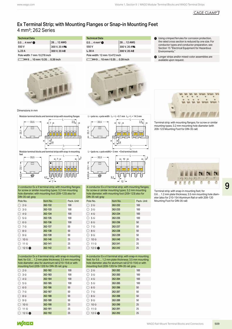
4 mm²; 262 SeriesModular Ex Terminal Block; with Mounting Flange or Snap-In Mounting Foot
2-conductor Ex e II terminal block; with mounting flange; for screw or similar mounting types; 3.2 mm mounting hole diameter; with mounting foot (209-123) also for DIN-35 rail
4-conductor Ex e II terminal block; with mounting flange; for screw or similar mounting types; 3.2 mm mounting hole diameter; with mounting foot (209-123) also for DIN-35 rail
Color Item No. Pack. Unit Color Item No. Pack. Unitlight gray 4 262-130 100 (50) light gray 4 262-230 100 (50)
2-conductor Ex e II terminal block; with snap-in mounting foot; for 0.6 … 1.2 mm plate thickness; 3.5 mm mounting hole diameter; also for aluminum rail (210-154) or with mounting foot (209-120) for DIN-35 rail
4-conductor Ex e II terminal block; with snap-in mounting foot; for 0.6 … 1.2 mm plate thickness; 3.5 mm mounting hole diameter; also for aluminum rail (210-154) or with mounting foot (209-120) for DIN-35 rail
light gray 4 262-180 100 (50) light gray 4 262-280 100 (50)
Space-saving 2-conductor Ex e II end terminal block; without protruding snap-in mounting foot; for terminal strips with snap-in mounting feet
Space-saving 4-conductor Ex e II end terminal block; without protruding snap-in mounting foot; for terminal strips with snap-in mounting feet
light gray 4 262-181 100 (50) light gray 4 262-281 100 (50)
Accessories; 262 SeriesMarking accessories, see Section 14
Technical Data Technical Data0.5 … 4 mm² 1 28 … 12 AWG 0.5 … 4 mm² 1 28 … 12 AWG550 V 300 V, 20 AU 550 V 300 V, 20 AUIN 23 A 300 V, 20 A2 IN 30 A 300 V, 20 A2Terminal block width: 7 mm / 0.276 inch Terminal block width: 12 mm / 0.472 inchL 9 … 10 mm / 0.35 … 0.39 inch L 9 … 10 mm / 0.35 … 0.39 inch
1 Using crimped ferrules for corrosion protection, the rated cross section is reduced by one size. For conductor types and conductor preparation, see Section 15 “Electrical Equipment for Hazardous Environments.”
CAGE CLAMP® termination:Inserting a conductor.
Commoning with comb-style jumper bar.
End plate; with mounting flangegray 262-363 50
End plate; with snap-in mounting footgray 262-373 50
Comb-style jumper bar; insulated; reduces maximum conductor size to 2.5 mm²; IN 16 A; gray
2-way 262-402 25
Operating tool; insulated; for comb-style jumper bar2-way 209-132 1
Aluminum mounting rail; 1000 mm long; 18 mm wide; 7 mm high
210-154 1
Plastic end stop; with WSB marker slot; for aluminum rail (210-154); 6 mm wide
209-122 25
Mounting foot; for DIN-35 rail; snaps onto terminal blocks with snap-in mounting foot; 6.4 mm wide
gray 209-120 25
Mounting screw; for mounting foot (209-120)209-119 500 (50)
Mounting foot with screw; for DIN-35 rail; can be screwed on terminal blocks with mounting flange; 6.4 mm wide
gray 209-123 25
Mounting adapter; for DIN-35 rail; can be used as end plate; 6.5 mm wide
gray 209-137 25
Operating tool with a partially insulated shaft; Type 2; (3.5 x 0.5) mm blade
210-720 1
9
509
www.wago.com
12
9,2
12 3L
33,5
4,5
3
4,2
7
4,5
33,57
L
2,8L1
L2
6
12 2,5L
33,533,5 7 2,5
62,8
L
L1
L2
23,1
23,1
23,1
23,1
Modular terminal blocks and terminal strips with snap-in mounting feet
Modular terminal blocks and terminal strips with mounting flanges
L = (pole no. x pole width) + 3 mm • End terminal block
L = pole no. x pole width L1 = L + 8.1 mm L2 = L + 14.5 mm
WAGO Rail-Mount Terminal Blocks and Connectors
Volume 1, Section 9 | WAGO Modular Terminal Blocks and WAGO Terminal Strips
Technical Data Technical Data0.5 … 4 mm² 1 28 … 12 AWG 0.5 … 4 mm² 1 28 … 12 AWG550 V 300 V, 20 AU 550 V 300 V, 20 AUIN 23 A 300 V, 20 A2 IN 30 A 300 V, 20 A2Pole width: 7 mm / 0.276 inch Pole width: 12 mm / 0.472 inchL 9 … 10 mm / 0.35 … 0.39 inch L 9 … 10 mm / 0.35 … 0.39 inch
1 Using crimped ferrules for corrosion protection, the rated cross section is reduced by one size. For conductor types and conductor preparation, see Section 15 “Electrical Equipment for Hazardous Environments.”
3 Longer strips and/or mixed-color assemblies are available upon request.
Terminal strip; with mounting flanges; for screw or similar mounting types; 3.2 mm mounting hole diameter (with 209-123 Mounting Foot for DIN-35 rail)
Terminal strip; with snap-in mounting feet; for 0.6 … 1.2 mm plate thickness; 3.5 mm mounting hole diam-eter (also for 210-154 Aluminum Rail or with 209-120 Mounting Foot for DIN-35 rail)
4 mm²; 262 SeriesEx Terminal Strip; with Mounting Flanges or Snap-in Mounting Feet
2-conductor Ex e II terminal strip; with mounting flanges; for screw or similar mounting types; 3.2 mm mounting hole diameter; with mounting foot (209-123) also for DIN-35 rail; gray
4-conductor Ex e II terminal strip; with mounting flanges; for screw or similar mounting types; 3.2 mm mounting hole diameter; with mounting foot (209-123) also for DIN-35 rail; gray
Pole No. Item No. Pack. Unit Pole No. Item No. Pack. Unit2 4 262-132 100 2 4 262-232 100
3 4 262-133 100 3 4 262-233 100
4 4 262-134 100 4 4 262-234 100
5 4 262-135 100 5 4 262-235 100
6 4 262-136 100 6 4 262-236 50
7 4 262-137 50 7 4 262-237 50
8 4 262-138 50 8 4 262-238 50
9 4 262-139 50 9 4 262-239 50
10 4 262-140 25 10 4 262-240 25
11 4 262-141 25 11 4 262-241 25
12 4 2 262-142 25 12 4 2 262-242 25
2-conductor Ex e II terminal strip; with snap-in mounting feet; for 0.6 … 1.2 mm plate thickness; 3.5 mm mounting hole diameter; also for aluminum rail (210-154) or with mounting foot (209-120) for DIN-35 rail; gray
4-conductor Ex e II terminal strip; with snap-in mounting feet; for 0.6 … 1.2 mm plate thickness; 3.5 mm mounting hole diameter; also for aluminum rail (210-154) or with mounting foot (209-120) for DIN-35 rail; gray
2 4 262-182 100 2 4 262-282 100
3 4 262-183 100 3 4 262-283 100
4 4 262-184 100 4 4 262-284 100
5 4 262-185 100 5 4 262-285 100
6 4 262-186 50 6 4 262-286 50
7 4 262-187 50 7 4 262-287 50
8 4 262-188 50 8 4 262-288 50
9 4 262-189 50 9 4 262-289 50
10 4 262-190 25 10 4 262-290 25
11 4 262-191 25 11 4 262-291 25
12 4 2 262-192 25 12 4 2 262-292 25
Dimensions in mm
9

510
www.wago.com
WAGO Rail-Mount Terminal Blocks and Connectors
Volume 1, Section 9 | WAGO Modular Terminal Blocks and WAGO Terminal Strips
Test plug module; without locking latches; snaps together; for 2-conductor terminal blocksModule width: 5 mm
Test plug module; without locking latches; snaps together; for 2-conductor terminal blocksModule width: 6 mm
Test plug module; without locking latches; snaps together; for 2-conductor terminal blocksModule width: 7 mm
Color Item No. Pack. Unit Color Item No. Pack. Unit Color Item No. Pack. Unitgray 249-135 100 (25) gray 249-136 100 (25) gray 249-137 100 (25)
Test plug module; without locking latches; snaps together; for 4-conductor terminal blocksModule width: 8 mm
Test plug module; without locking latches; snaps together; for 4-conductor terminal blocksModule width: 10 mm
Test plug module; without locking latches; snaps together; for 4-conductor terminal blocksModule width: 12 mm
gray 249-138 100 (25) gray 249-139 100 (25) gray 249-140 100 (25)
Test plug module; with locking latches; snaps together; for 2-conductor terminal blocksModule width: 5 mm
Test plug module; with locking latches; snaps together; for 2-conductor terminal blocksModule width: 6 mm
gray 260-404 100 (25) gray 261-404 100 (25)
Test plug module; with locking latches; snaps together; for 4-conductor terminal blocksModule width: 8 mm
Test plug module; without locking latches; snaps together; for 4-conductor terminal blocksModule width: 10 mm
gray 260-405 100 (25) gray 261-405 100 (25)
Accessories; for L-type test plug modules
260, 261 and 262 SeriesTest Plug Module; for Terminal Strips without Push-Buttons
Technical Data Technical Data Technical Datafor 260 Series for 261 Series (also 264 Series) for 262 SeriesTest voltage: 250 V / 500 V 1 Test voltage: 400 V / 800 V 1 Test voltage: 500 V / 800 V 1Test current: 0.5 A / 6 A 2 Test current: 0.5 A / 6 A 2 Test current: 0.5 A / 6 A 2Middle pressure: 2.2 N per pole Middle pressure: 2.2 N per pole Middle pressure: 2.2 N per pole
Test plug; with 500 mm cable; 2 mm Ø; max. 42 Vred 210-136 50
9

511
www.wago.com
WAGO Rail-Mount Terminal Blocks and Connectors
Volume 1, Section 9 | WAGO Modular Terminal Blocks and WAGO Terminal Strips
1 Maximum test voltage (touch contact): 48 V (test pins are not touch-proof)
2 Maximum test current (touch contact): 0.5 AMaximum test current: 6 A (if the test pins are securely connected in the clamping units)
Testing after the conductors have been terminated.
Testing via test plug modules snapped onto a terminal strip – wired or unwired. As touch contact is made with the CAGE CLAMP® (spring steel) unit, this testing type is lim-ited to maximum 0.5 A.
Distance between locking devices must be approximately 35 … 40 mm.
Snapping individual modules together to assemble a multi-pole test plug module.
9