Embed Size (px)
Citation preview

Microfluidically Loaded Highly Reconfigurable
Compact Antennas & RF Devices
Gokhan Mumcu
Associate ProfessorCenter for Wireless and Microwave Information Systems (WAMI)
Department of Electrical EngineeringUniversity of South Florida
4202 E. Fowler Ave., Tampa, FL, 33620
IEEE MTT/AP Orlando Chapter MeetingNovember 30th, 2016
Forum for Electromagnetic Research Methods and Application Techniques
(FERMAT)

Copyright
2
© The use of this work is restricted solely for academic purposes.
The author of this work owns the copyright and no reproduction
in any form is permitted without written permission by the
author.

Abstract
3
Reconfigurable radio frequency (RF) antennas and filters have drawn growing interest to enable compact and light-weight multifunctional systems for wireless communications, sensor networks, biomedical imaging, and remote sensing. Existing reconfigurable RF device design approaches that are based on material loadings, semiconductor and ferroelectric varactors, micromechanical systems (MEMS) switches and capacitors are today well-recognized to offer compact and cost-effective device implementations with high reconfiguration speeds. However, these technologies continue to exhibit limited performance in terms of key RF metrics such as power handling, frequency tunability bandwidth, pattern scanning range, efficiency, and frequency-agile capability. Consequently, novel alternative techniques that address the overall performance needs of reconfigurable RF devices are highly desirable to advance their capabilities and use into mainstream technologies.
This presentation focuses on novel reconfigurable RF antennas, filters, and imaging systems realized by resorting to innovative microfluidic based reconfiguration techniques. The operational principles of these devices rely on continuously movable microfluidic loads consisting of metal (in liquid or solid form) and dielectric solution volumes. The realization of the devices are carried out by utilizing microfluidics and microfabrication techniques with multilayered ultra-thin substrates to maximize the parasitic loading effect of the microfluidic loads for achieving high reconfiguration performances. It will be shown that the proposed microfluidic reconfiguration techniques offer significantly improved frequency tuning range (>4:1 and >2:1 in monopole antenna and filter topologies, respectively) without suffering from excessive loss factors and high power handling issues observed in conventional semiconductor based implementations. Another example design will demonstrate that the microfluidic reconfiguration techniques lead to low-cost mm-wave (30GHz) beam-scanning high-gain antenna arrays without necessitating the use of costly and lossy phase shifters.
Keywords: Reconfigurable antenna, filter, mm-wave, antenna array, microfluidics, liquid metal;

Biography
4
Gokhan Mumcu (S’03–M’09–SM’15) was born in Bursa, Turkey, on March 30, 1982. He
received the B.S. degree in electrical engineering from Bilkent University, Ankara, Turkey, in
2003, and the M.S. and Ph.D. degrees in electrical and computer engineering from The Ohio
State University, Columbus, in 2005 and 2008, respectively.
He is currently an Associate Professor at the Electrical Engineering Department of
University of South Florida, Tampa, FL. From 2009 to 2015, he was an Assistant Professor at
the Electrical Engineering Department of University of South Florida. His research interests
are small antennas, engineered materials, THz technologies, and reconfigurable RF devices,
antennas and arrays using microfluidic reconfiguration techniques.
Dr. Mumcu is the recipient of the 2014 CAREER award from the U.S. National Science
Foundation. He is also recipient of 2014 faculty outstanding research award from the
University of South Florida. He ranked first on the national university entrance exam taken
annually by over 1.5 million Turkish students in 1999. He received the 1999 international
education fellowship of the Turkish Ministry of Education. He was the recipient of a best
paper award at 2008 URSI National Radio Science Meeting, and the 2008 outstanding
dissertation award at The Ohio State University, ElectroScience Laboratory. He served as the
technical program committee co-chair of the 2013 IEEE International Symposium on
Antennas and Propagation and USNC/URSI National Radio Science Meeting and 2016
International Workshop on Antenna Technology (iWAT).

Reconfigurable RF Components for
Emerging Multifunctional Miniature Systems5
Passive RF components (such as filters and antennas) occupy a
significant footprint in wireless communication devices and system-
on-chip components.
Recent technology trends that pack many capabilities into small
platforms suffer from the size limitations of RF components.
Reconfigurable RF components hold promise to enable
consolidation of multiple RF front-ends (each serving for a
distinct sensing/communication functionality) into a single
multifunctional RF front-end.
More than 50% of a system-on-a-chip
consists of passive RF devices
Compact communication
systems with higher data rates

State-of-the-art Technologies for Implementing Reconfigurable RF Components
6
Semiconductor Technologies
Varactor Diodes: Variable capacitors that can be controlled with bias voltage.
PIN Diodes: ON/OFF RF switching functionality controlled with bias voltage.
Transistors: ON/OFF RF switches controlled with gate voltage.
Material Loadings
Magnetic materials: Permeability variation controlled with external magnetic field (e.g. yttrium iron garnet).
Ferroelectrics: Permittivity variation controlled with external electric field (e.g. barium strontium titanate).
Polymers: Physical size control with mechanical setups (e.g. stretching) or heat (e.g. shape shifting alloys).
Micro Electro Mechanical Systems (MEMS)
MEMS capacitors: Variable capacitors with bias voltage.
MEMS switches: ON/OFF RF switches controlled with bias voltage.
Advantages
Cost effective, high reconfiguration speed (except mechanical actuation of polymers), compact, low loss and
RF isolation (especially with MEMS technology)
Disadvantages
Power handling is limited due to intermodulation products, harmonics, and device construction.
Limited continuous frequency tunability bandwidth or frequency tuning in discrete steps.
Loss is still high for achieving high radiation efficiency.
Design complexity and high cost for systems that need many reconfigurable RF devices (e.g. beam-steering
arrays)

Microfluidics for Reconfigurable RF Components
7
Microfluidic Loading of RF devices with:
• Continuously movable metals (in liquid or solid form)
• Dielectric solutions
• Fluidic channels utilizing ultra-thin walls
offers new possibilities & degrees of freedom for RF design:
Miniaturization
Large Frequency Tuning Range
High Power Handling
Low Cost Beam-Steering
Low Loss
Filled
Location
Ground
PlaneSubstrate of the Feed
Network
Liquid Crystalline
Polymer (LCP)
Polydimethylsiloxane
(PDMS)
Rexolite
Feed
Network
Microfluidic
Channels
Complex Material Development
Interdisciplinary projects & Collaboration of different departments
Fundamental Understanding
Applied Mathematics, Physics
Electrical Engineering
Prototype Development &
Device Testing
EM & RF Engineers
Material Production
Material Science, Mechanical
Engineering
Presentation Highlights –Microfluidically Loaded Reconfigurable Compact RF Antennas and Filters
8
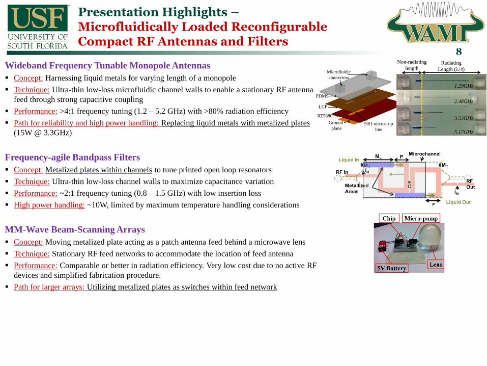
Wideband Frequency Tunable Monopole Antennas
Concept: Harnessing liquid metals for varying length of a monopole
Technique: Ultra-thin low-loss microfluidic channel walls to enable a stationary RF antenna
feed through strong capacitive coupling
Performance: >4:1 frequency tuning (1.2 – 5.2 GHz) with >80% radiation efficiency
Path for reliability and high power handling: Replacing liquid metals with metalized plates
(15W @ 3.3GHz)
Frequency-agile Bandpass Filters
Concept: Metalized plates within channels to tune printed open loop resonators
Technique: Ultra-thin low-loss channel walls to maximize capacitance variation
Performance: ~2:1 frequency tuning (0.8 – 1.5 GHz) with low insertion loss
High power handling: ~10W, limited by maximum temperature handling considerations
MM-Wave Beam-Scanning Arrays
Concept: Moving metalized plate acting as a patch antenna feed behind a microwave lens
Technique: Stationary RF feed networks to accommodate the location of feed antenna
Performance: Comparable or better in radiation efficiency. Very low cost due to no active RF
devices and simplified fabrication procedure.
Path for larger arrays: Utilizing metalized plates as switches within feed network
RF In
Liquid
metal
Liquid
out
Liquid
in PDMS
LCP
RT5880
Ground
plane50W microstrip
line
Microfluidic
connectors
Non-radiating
lengthRadiating
Length (l/4)
1.29GHz
2.48GHz
5.17GHz
3.53GHz
Fabrication Techniques
9
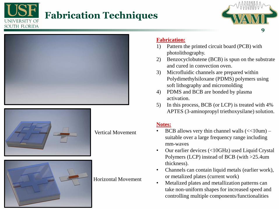
Fabrication:
1) Pattern the printed circuit board (PCB) with
photolithography.
2) Benzocyclobutene (BCB) is spun on the substrate
and cured in convection oven.
3) Microfluidic channels are prepared within
Polydimethylsiloxane (PDMS) polymers using
soft lithography and micromolding
4) PDMS and BCB are bonded by plasma
activation.
5) In this process, BCB (or LCP) is treated with 4%
APTES (3-aminopropyl triethoxysilane) solution.
Notes:
• BCB allows very thin channel walls (<<10um) –
suitable over a large frequency range including
mm-waves
• Our earlier devices (<10GHz) used Liquid Crystal
Polymers (LCP) instead of BCB (with >25.4um
thickness).
• Channels can contain liquid metals (earlier work),
or metalized plates (current work)
• Metalized plates and metallization patterns can
take non-uniform shapes for increased speed and
controlling multiple components/functionalities
Vertical Movement
Horizontal Movement
Liquid Metal Wideband Frequency Tunable Monopole Antenna
– Operation Principle10
RF In
Liquid
metal
Liquid
out
Liquid
in PDMS
LCP
RT5880
Ground
plane50W microstrip
line
Microfluidic
connectors
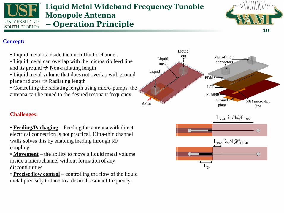
Concept:
• Liquid metal is inside the microfluidic channel.
• Liquid metal can overlap with the microstrip feed line
and its ground Non-radiating length
• Liquid metal volume that does not overlap with ground
plane radiates Radiating length
• Controlling the radiating length using micro-pumps, the
antenna can be tuned to the desired resonant frequency.
Challenges:
• Feeding/Packaging – Feeding the antenna with direct
electrical connection is not practical. Ultra-thin channel
walls solves this by enabling feeding through RF
coupling.
• Movement – the ability to move a liquid metal volume
inside a microchannel without formation of any
discontinuities.
• Precise flow control – controlling the flow of the liquid
metal precisely to tune to a desired resonant frequency.
LRad=l1/4@fLOW
LRad=l2/4@fHIGH
LO
Liquid Metal Flow Characterization for
Maximum Antenna Length
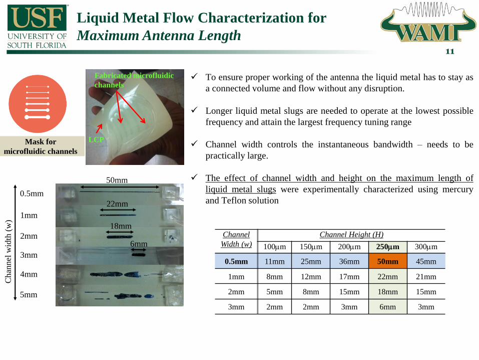
Fabricated microfluidic
channels
LCP
To ensure proper working of the antenna the liquid metal has to stay as
a connected volume and flow without any disruption.
Longer liquid metal slugs are needed to operate at the lowest possible
frequency and attain the largest frequency tuning range
Channel width controls the instantaneous bandwidth – needs to be
practically large.
The effect of channel width and height on the maximum length of
liquid metal slugs were experimentally characterized using mercury
and Teflon solution
11
Mask for
microfluidic channels
0.5mm
50mm
3mm
1mm
2mm
4mm
5mm
22mm
18mm
6mm
Ch
ann
el w
idth
(w
)
Channel
Width (w)
Channel Height (H)
100mm 150mm 200mm 250mm 300mm
0.5mm 11mm 25mm 36mm 50mm 45mm
1mm 8mm 12mm 17mm 22mm 21mm
2mm 5mm 8mm 15mm 18mm 15mm
3mm 2mm 2mm 3mm 6mm 3mm
Liquid Metal Flow Characterization for
Widest Feed Overlap & Feed/Antenna Transition
12
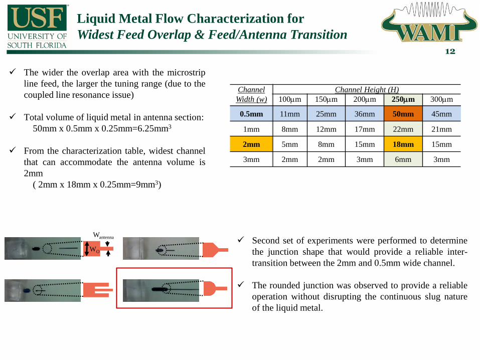
WO
Wantenna
The wider the overlap area with the microstrip
line feed, the larger the tuning range (due to the
coupled line resonance issue)
Total volume of liquid metal in antenna section:
50mm x 0.5mm x 0.25mm=6.25mm3
From the characterization table, widest channel
that can accommodate the antenna volume is
2mm
( 2mm x 18mm x 0.25mm=9mm3)
Second set of experiments were performed to determine
the junction shape that would provide a reliable inter-
transition between the 2mm and 0.5mm wide channel.
The rounded junction was observed to provide a reliable
operation without disrupting the continuous slug nature
of the liquid metal.
Channel
Width (w)
Channel Height (H)
100mm 150mm 200mm 250mm 300mm
0.5mm 11mm 25mm 36mm 50mm 45mm
1mm 8mm 12mm 17mm 22mm 21mm
2mm 5mm 8mm 15mm 18mm 15mm
3mm 2mm 2mm 3mm 6mm 3mm
Liquid Metal Wideband Frequency Tunable Monopole Antenna – Design & Simulations
13
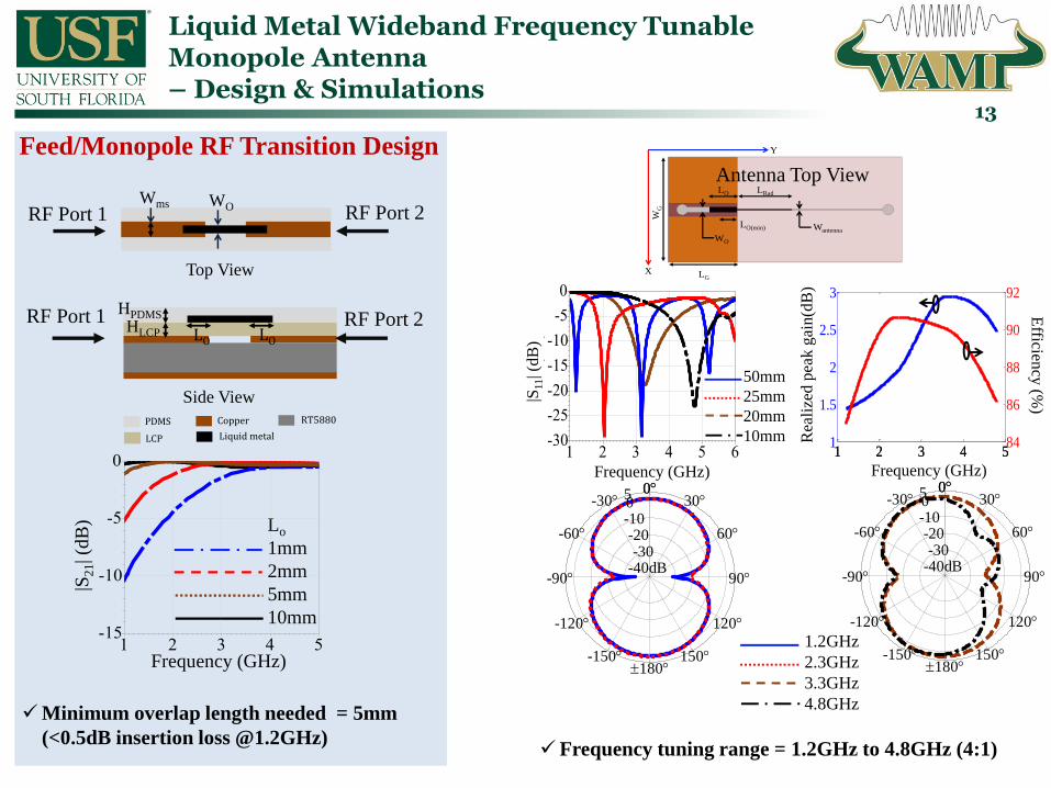
Wantenna
WO
LO LRad
LG
WG
LO(min)
Y
X
1 2 3 4 51
1.5
2
2.5
3
1 2 3 4 584
86
88
90
92
50mm
25mm
20mm
10mm
Frequency (GHz)
Rea
lize
d p
eak
gai
n(d
B)
Efficien
cy (%
)|S11| (
dB
)
Frequency (GHz)
1.2GHz
2.3GHz
3.3GHz
4.8GHz
50-10-20-30
-40dB
030
60
90
120
150
0-30
-60
-90
-120
-150180
50-10-20-30
-40dB
030
60
90
120
150
0-30
-60
-90
-120
-150180
Frequency tuning range = 1.2GHz to 4.8GHz (4:1)
HLCP
HPDMS
WOWms
Lo
1mm
2mm
5mm
10mm
Frequency (GHz)
|S21| (
dB
)
Antenna Top View
Feed/Monopole RF Transition Design
HLCP
HPDMS
WOWms
RF Port 1 RF Port 2
Top View
Side View
RF Port 2RF Port 1
Minimum overlap length needed = 5mm
(<0.5dB insertion loss @1.2GHz)
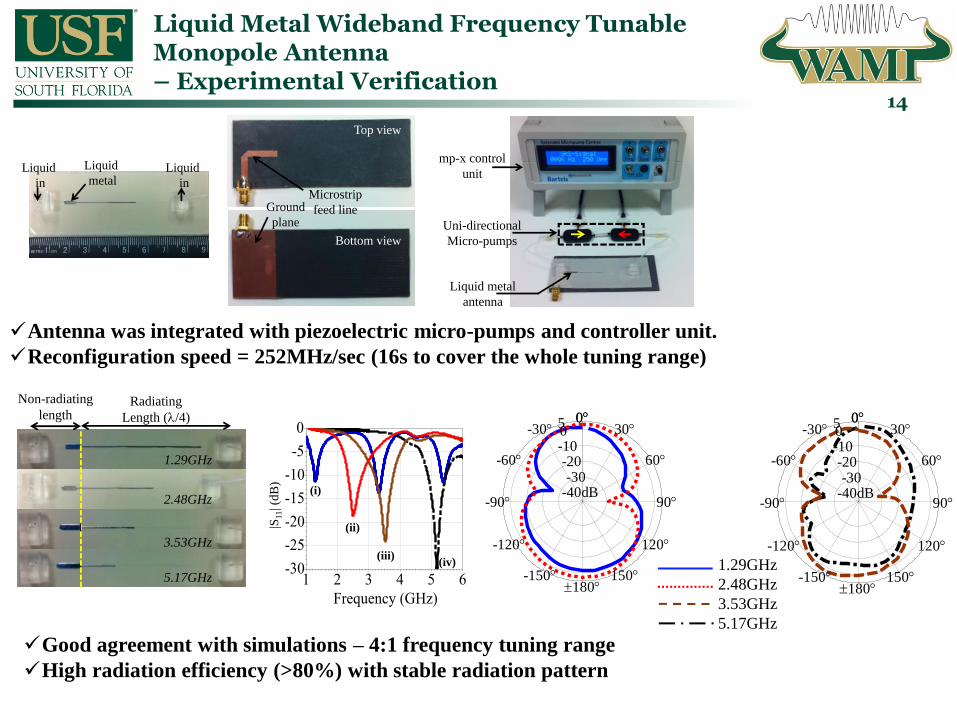
Liquid Metal Wideband Frequency Tunable Monopole Antenna – Experimental Verification
14
Liquid
in
Liquid
in
Liquid
metalMicrostrip
feed lineGround
plane
Top view
Bottom view
Non-radiating
lengthRadiating
Length (l/4)
1.29GHz
2.48GHz
5.17GHz
3.53GHz
(i)
(ii)
(iii)(iv)
|S11| (
dB
)
50-10-20-30
-40dB
030
60
90
120
150
0-30
-60
-90
-120
-150180
50-10-20-30
-40dB
030
60
90
120
150
0-30
-60
-90
-120
-150180
1.29GHz
2.48GHz
3.53GHz
5.17GHz
mp-x control
unit
Uni-directional
Micro-pumps
Liquid metal
antenna
Antenna was integrated with piezoelectric micro-pumps and controller unit.
Reconfiguration speed = 252MHz/sec (16s to cover the whole tuning range)
Good agreement with simulations – 4:1 frequency tuning range
High radiation efficiency (>80%) with stable radiation pattern

Liquid Metal Wideband Frequency Tunable Monopole Antenna – Extension to Antenna Arrays
15
The liquid metal monopole antenna can be used to
construct high gain frequency tunable antenna
arrays.
The array is operated with single pump by
resorting to meandered and/or interconnected
microfluidic channels.
Specifically, a 4 element array was demonstrated.
The inter-element spacing was small to prevent
grating lobes but large enough to reduce mutual
coupling between the antenna elements.
Frequency tuning range of the array (2:1): 2.5
to 5GHz
Measured broadside gain: 6.2dB @ 2.5 GHz,
8dB @ 5GHz
d b=0
P1 P2 P3 P4
25mm
Liquid
outLiquid
in
2.5GHz
5GHz
50-10-20-30
-40dB
030
60
90
120
150
0-30
-60
-90
-120
-150180
mp6-OEM
driver circuit
Micro-pumps
Microcontroller
Y
Z
50-10-20-30
-40dB
030
60
90
120
150
0-30
-60
-90
-120
-150180 2.5GHz
5GHz

Transitioning to Liquid Metal Free RF Components
16
Liquid metals are either toxic (e.g. mercury) or suffer from excessive oxidization (e.g. Galinstan) that causes
them to wet the surfaces they come in contact with (i.e. sticking)
Several research groups are working on reliable actuation of non-toxic liquid metals (such as encapsulating
liquid metal in carrier fluid, using electrolytes to continuously remove oxide layer, electrowetting, etc.).
However, there is still no established reliable technique available.
Even though the liquid metal actuation issues are solved, their conductivity is 10 to 20 times lower. Hence, the
high power handling and loss performance of the devices will be limited with this conductivity layer
Our Solution: Utilize metalized plates within microfluidic channels to achieve low loss and high power
handling RF devices.
Metalized plate (quartz, PCB, glass, etc) in
microfluidic channel
LCP is also replaced in certain implementations with lower
loss dielectric polymer BCB (Benzocyclobutene).
BCB offers thinner layers (< 25µm), higher power handling,
and a more convenient PDMS/PCB bonding procedure.
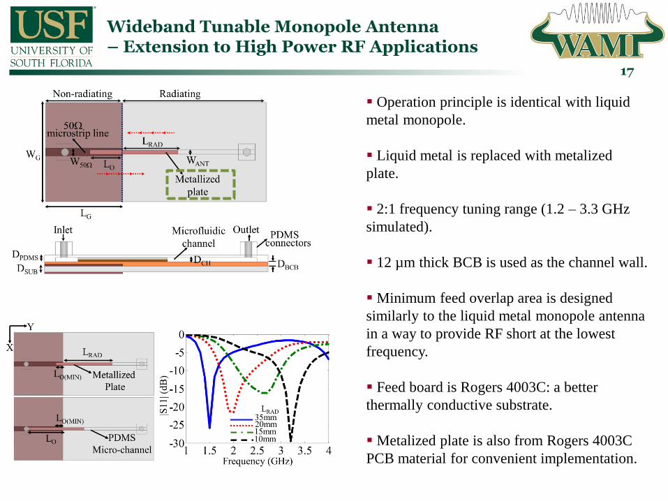
Wideband Tunable Monopole Antenna – Extension to High Power RF Applications
17
Operation principle is identical with liquid
metal monopole.
Liquid metal is replaced with metalized
plate.
2:1 frequency tuning range (1.2 – 3.3 GHz
simulated).
12 µm thick BCB is used as the channel wall.
Minimum feed overlap area is designed
similarly to the liquid metal monopole antenna
in a way to provide RF short at the lowest
frequency.
Feed board is Rogers 4003C: a better
thermally conductive substrate.
Metalized plate is also from Rogers 4003C
PCB material for convenient implementation.

Wideband Tunable Monopole Antenna – Experimental Verification
18
2:1 measured frequency tuning range from 1.7 to 3.5 GHz
Measured and simulated radiation gain patterns agree
well.
A more compact bi-directional pumping unit was
developed using on chip mp6-OEM drivers (Bartels).
Reconfiguration speed: 1550MHz/s (1.15s for entire
tuning range). Significantly faster as compared to liquid
metal since a low viscosity dielectric liquid FC-40 was
satisfactory for plate movement.
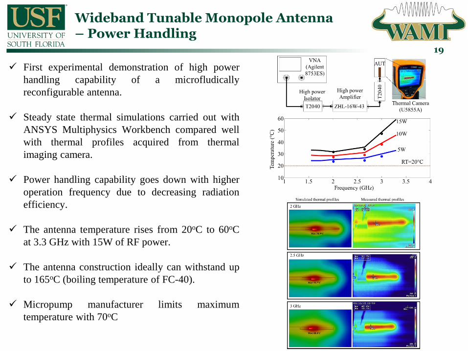
Wideband Tunable Monopole Antenna – Power Handling
19
First experimental demonstration of high power
handling capability of a microfludically
reconfigurable antenna.
Steady state thermal simulations carried out with
ANSYS Multiphysics Workbench compared well
with thermal profiles acquired from thermal
imaging camera.
Power handling capability goes down with higher
operation frequency due to decreasing radiation
efficiency.
The antenna temperature rises from 20oC to 60oC
at 3.3 GHz with 15W of RF power.
The antenna construction ideally can withstand up
to 165oC (boiling temperature of FC-40).
Micropump manufacturer limits maximum
temperature with 70oC

Frequency-Agile Bandpass Filters– Initial Work with Liquid Metals & Tubes
20
Microfluidics For Reconfigurable Filters:
• Liquid Metals: Can dynamically change shape of resonators
• Metalized Plates: Maximized capacitance variation (from 0pF!)
• High power handling
• Large frequency tuning range
• Lower loss as compared to semiconductor/ferroelectric varactors
d=d1 d3 d4 d5
Frequency (GHz)
dB
(S11
) &
dB
(S2
1)
0.55
0.60
0.65
0.70
0.75
0.80
0.85
0.90
0.95
0.50
1.00
-25
-20
-15
-10
-5
-30
0
freq, GHz
dB
(S
(2,1))
dB
(S
(1,1))
dB
(S
(4,3))
dB
(S
(3,3))
dB
(S
(6,5))
dB
(S
(5,5))
dB
(S
(8,7))
dB
(S
(7,7))
• Limited tunability due to thick tube walls and
rounded shape: 650 – 870 MHz (29%)
• < 3dB insertion loss with 5% fractional bandwidth
• Not reliable due to the liquid metals and tubed
construction
Increase tuning range and decrease loss with
ultra-thin microfluidic channel walls (LCP)
Replace liquid metal with metalized plate

Open Loop Resonators Loaded with Microfluidically Controlled Metalized Plates
21
• Simulated frequency tuning range: 0.6 GHz to 1.5 GHz
• Simulate quality factor (Q) : 72 to 160
• Hybrid (circuit + full wave) model for reducing the full wave
simulation requirements. Faster design of high order filters
• 6mm displacement needed to cover the tuning range. Can be
miniaturized further with thinner insulator.
0.6 0.8 1.0 1.2 1.4 1.60.4 1.8
-4
-3
-2
-1
-5
0
freq, GHz
dB
(C
apacitanceextraction5..S
(2,2))
dB
(C
apacitanceextraction5..S
(1,1))
dB
(C
apacitanceextraction4..S
(2,2))
dB
(C
apacitanceextraction4..S
(1,1))
dB
(C
apacitanceextraction3..S
(2,2))
dB
(C
apacitanceextraction3..S
(1,1))
dB
(C
apacitanceextraction2..S
(1,1))
dB
(C
apacitanceextraction2..S
(2,2))
dB
(C
apacitanceextraction..S
(1,1))
dB
(C
apacitanceextraction..S
(2,2))
Frequency (GHz)
S11
(dB
)
C5
C4
C3C2
C1
C
L
r
C1 C2
PDMS
Channel
LCP
Resonator
Roger
6010.2
Ground
Metallized plate
Represents moving plate
RF Port 1

Example 2-pole filter design with 10% FBW
22• To have constant FBW, the external quality factor (Qe) and coupling coefficient (k) must be kept
constant across the entire frequency tuning range of 0.6 GHz to 1.5 GHz.
• Qe was stabilized by adding series lumped inductors to the tapping lines. The tapping location and
lumped inductor value was optimized to achieve desired Qe value.
• k was stabilized by selecting a resonator arrangement that relies on mixed magnetic and electric
coupling. The coupling gap was selected to achieve the desired k value.
• Further stabilization in Qe and k variation is possible with rectangular resonator shapes but this was not
pursued for the example filter demonstrations.
Coupling Gap
Tapping
location
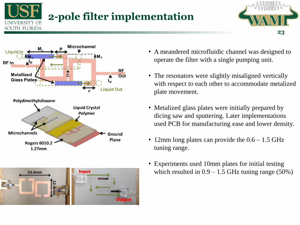
2-pole filter implementation
23
24.4mm
12
.4m
m
Input
Output
• A meandered microfluidic channel was designed to
operate the filter with a single pumping unit.
• The resonators were slightly misaligned vertically
with respect to each other to accommodate metalized
plate movement.
• Metalized glass plates were initially prepared by
dicing saw and sputtering. Later implementations
used PCB for manufacturing ease and lower density.
• 12mm long plates can provide the 0.6 – 1.5 GHz
tuning range.
• Experiments used 10mm plates for initial testing
which resulted in 0.9 – 1.5 GHz tuning range (50%)
Experimental verification of the 2-pole filter
24
1.0 1.50.5 2.0
-30
-20
-10
-40
0
freq, GHz
dB(S
(2,1
))dB
(S(4
,3))
dB(S
(6,5
))dB
(S(1
0,9)
)dB
(S(1
2,11
))dB
(S(1
,1))
dB(S
(3,3
))dB
(S(5
,5))
dB(S
(9,9
))dB
(S(1
1,11
))
S2
1(d
B)
Frequency (GHz)
Simulated
1.0 1.50.5 2.0
-30
-20
-10
-40
0
freq, GHz
dB(S
(4,3
))dB
(S(1
0,9)
)dB
(S(1
6,15
))dB
(S(2
2,21
))dB
(S(2
,1))
dB(S
(3,3
))dB
(S(9
,9))
dB(S
(15,
15))
dB(S
(21,
21))
dB(S
(1,1
))
MeasuredS
21
(dB
)
Frequency (GHz)
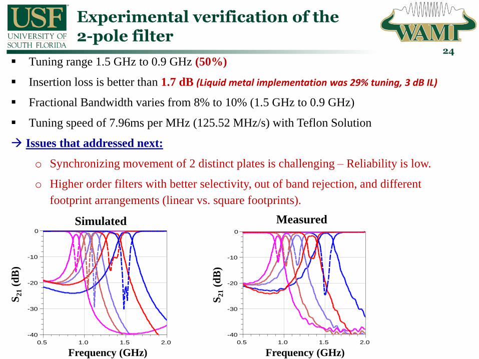
Tuning range 1.5 GHz to 0.9 GHz (50%)
Insertion loss is better than 1.7 dB (Liquid metal implementation was 29% tuning, 3 dB IL)
Fractional Bandwidth varies from 8% to 10% (1.5 GHz to 0.9 GHz)
Tuning speed of 7.96ms per MHz (125.52 MHz/s) with Teflon Solution
Issues that addressed next:
o Synchronizing movement of 2 distinct plates is challenging – Reliability is low.
o Higher order filters with better selectivity, out of band rejection, and different
footprint arrangements (linear vs. square footprints).

4-pole Filters &Selectively Metallized Plates
25
Qe and k design follows the same procedures. Simulated tuning range is 1.5 GHz to 0.6 GHz.
Fractional bandwidth is 5% +/-1%.
Insertion loss is < 4.7dB
>40dB out of band rejection.
A selectively metalized plate is utilized to remove the synchronization issues.
Channel and plate is modified to take Z-shape to increase tuning speed (7x).
Metallized
Areas
Liquid In Liquid Out
RF In
RF Out
RCl
RPl
RP
w
RC
w
MicrochannelRoger 5880 plate
Metallized
Areas
Liquid In
Liquid Out
RF In
RF Out
ZCl
ZPl
RP
w
RC
w
Microchannel
Zin
Roger 5880
plate
Frequency (GHz)S
21
(dB
)
Z-shaped plate and channel
Straight rectangular plate and channel

4-pole Filters: Experimental Verification
26
Liquid In
Liquid Out
ZPl
ZPl
ZP
l
ZP
l
ZC
l
ZC
l
Roff
Roff
RF In
RF Out
g12
g12
g23
Alternative
Footprint Design
Frequency (GHz)
S2
1(d
B)
Frequency (GHz)
S2
1(d
B)
Frequency (GHz)
S2
1(d
B)
Measured tuning range is 1.5 GHz to 0.8 GHz
Fractional bandwidth is 5% +/-1%.
Insertion loss is < 4.7dB
>40dB out of band rejection.
2MHz per ms (300ms for 6mm motion range)
51.5 × 14 mm2
37.6 × 34.2 mm2
6mm
34
.2m
m
37.58mm
Ba
rtels MP
-6
Micro
pu
mp
s
Inp
ut
Ou
tpu
t
PDMS
Selectively Metallized Plate
LCP
PCB with Printed Resonators
Ground
4th order 2:1 Frequency-Agile Bandpass Filter

Pad to Ground
S0 S1S2 S3
S4
Sg
RL
RW
Plate
R
Combline Filters for Wider Tuning Range and High Power Handling(publication pending)
27
Microfluidic
Channel
Metallized
Plate
PD
MS
Rogers 6010.2
Gro
un
dH
alf
Wavele
ngth
Reso
nato
rP
ad
to
Gro
un
d
BCB
1
1.5
2
2.5
3
3.5
4
4.5
185
190
195
200
205
210
215
0 2 4 6 8 10 12
Un
loaded
Qu
ali
ty F
acto
r (Q
u)
Fre
qu
ency (G
Hz)
Plate Displacement (mm)
Frequency tuning is based on “length variation” and moderate
capacitive loading.
6um thick BCB is used to maximize capacitive coupling between
metalized plate and the printed resonator.
Quality factor (resonator loss) remains constant over large tuning
range (1.5 – 4 GHz).
11.5 mm movement range for entire tuning range
Substrate Stack-up View Top View

4th order Combline Filter Performance(publication pending)
28
CL
PL
PO
CO
PW
PL
PI
PO 3
8.0
1 m
m
34.975 mm
Barte
ls MP
-6
Mic
rop
um
ps
Inp
ut
Ou
tpu
t
0.5 2.0 4.0 6.0 8.0 10.0 12.0
0
-30
-20
-10
-40
Frequency (GHz)
S11
& S
21
(dB
)
-5
-15
-25
-35
Design utilizes a capacitive coupling and stub loading mechanism and input/output ports to maintain external quality
factor constant across the wide frequency tuning range (1.5 – 4 GHz, 2.7:1).
Fractional bandwidth is ~5% +/- 2%.
Insertion loss is < 3 dB.
Footprint, 34 x 38 mm2
2.5 MHz per ms.
Printed Resonators & Grounding Pads
Metalized Plate
Filter PrototypeMeasured Response

4th order Combline Filter Power Handling(publication pending)
29
From the correlation between simulation and
experiments, we expect that the maximum power
handling is ~30W (780C) without heat sink.
Highest tuning range and power handling capability
among the microfluidically reconfigurable RF filters
despite its higher order design.
Future work: Replace PDMS with Quartz/Glass.
Thermal simulation for 15 W input power
level at 2.5 GHz.
480C is the highest expected temperature.
Mini-circuit
High Power Amp
ZHL-16W-43-S+
Attenuator
Isolator
ENA
`
Experiment 15 W input power level at 2.5 GHz.
460C is the highest temperature.
MM-Wave Beam-Scanning Arrays
30
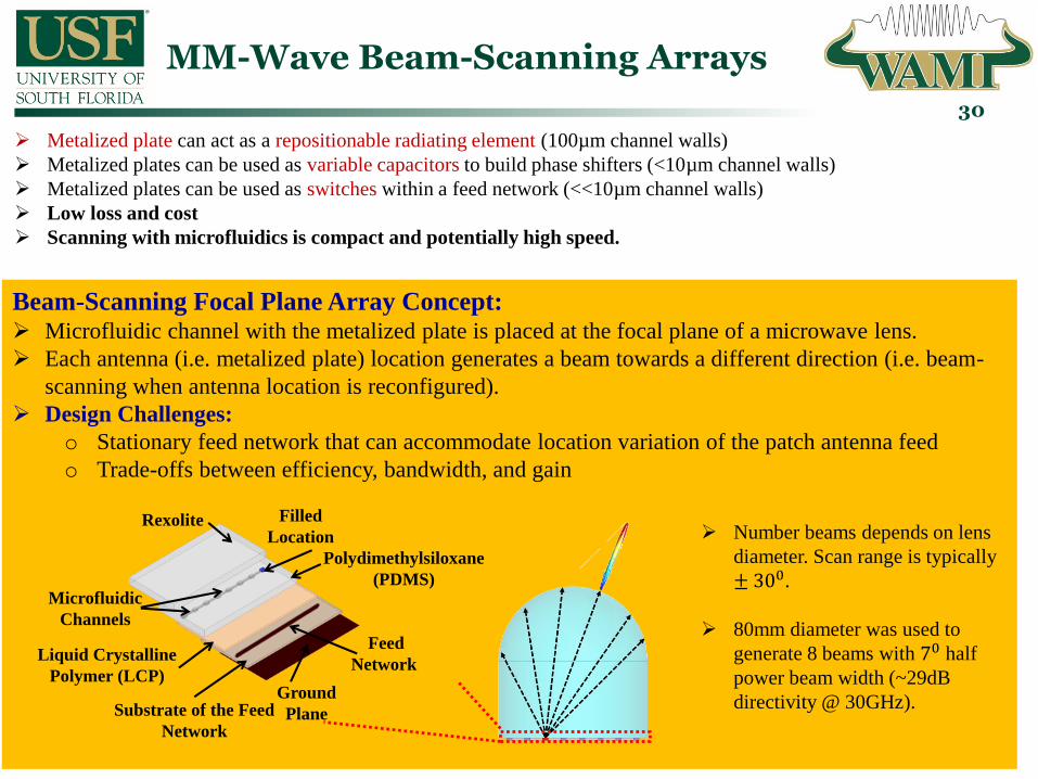
Metalized plate can act as a repositionable radiating element (100µm channel walls)
Metalized plates can be used as variable capacitors to build phase shifters (<10µm channel walls)
Metalized plates can be used as switches within a feed network (<<10µm channel walls)
Low loss and cost
Scanning with microfluidics is compact and potentially high speed.
Beam-Scanning Focal Plane Array Concept: Microfluidic channel with the metalized plate is placed at the focal plane of a microwave lens.
Each antenna (i.e. metalized plate) location generates a beam towards a different direction (i.e. beam-
scanning when antenna location is reconfigured).
Design Challenges:
o Stationary feed network that can accommodate location variation of the patch antenna feed
o Trade-offs between efficiency, bandwidth, and gain
Filled
Location
Ground
PlaneSubstrate of the Feed
Network
Liquid Crystalline
Polymer (LCP)
Polydimethylsiloxane
(PDMS)
Rexolite
Feed
Network
Microfluidic
Channels
Number beams depends on lens
diameter. Scan range is typically
± 3 0.
80mm diameter was used to
generate 8 beams with 70 half
power beam width (~29dB
directivity @ 30GHz).

Microfluidic FPA Resonant Corporate Feed Network
31
λg /2
O.C
λg
λg /2
λg
O.C
λg /2
O.C
λg
λg /2
O.C
λg/2 λg/2
O.C
Line of Symmetry
O.C O.C
𝝀𝒈 separation guarantees 3dB HPBW intersection
between beams as they are scanned.
Resonant feed network directs the RF energy from the feed point to antenna element by making use of
open-circuit conditions.
It consists of multiples of λg microstrip lines
Can take different forms: corporate, straight, edge vs. center fed.
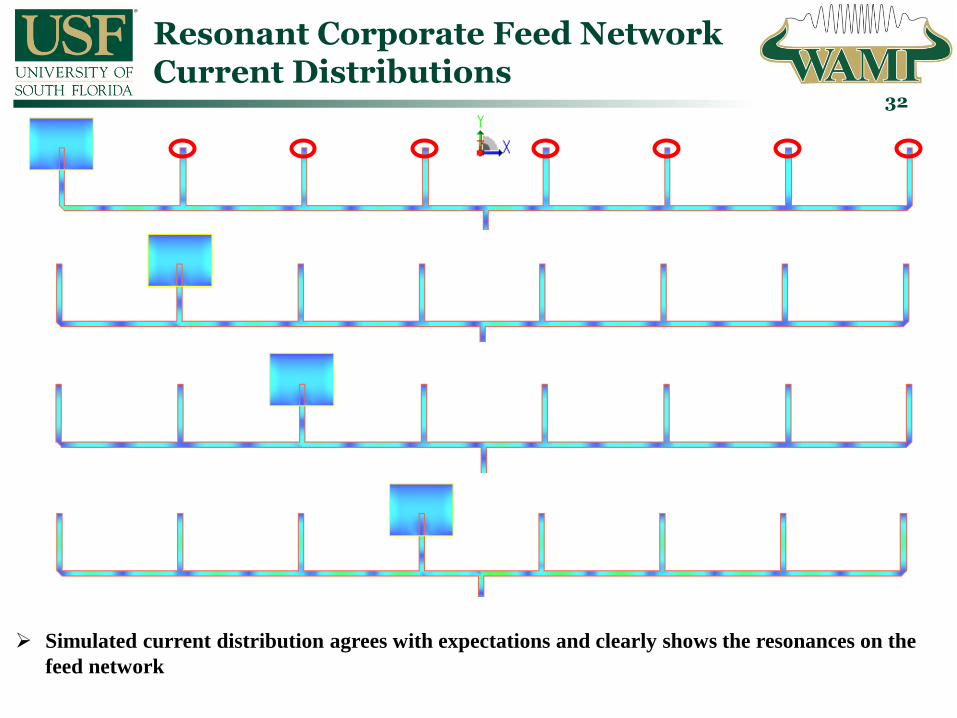
Resonant Corporate Feed Network Current Distributions
32
Simulated current distribution agrees with expectations and clearly shows the resonances on the
feed network

Resonant Corporate Feed Network: Analytical Model
33
1) Design the 𝝀𝒈/𝟐 resonator
28 29 30 31 32-40
-30
-20
-10
0
Frequency [GHz]
|S1
1| [d
B]
Antenna
Equivalent Circuit
2) Extract equivalent circuit model for
a stub loaded with antenna
𝑄𝑠𝑡𝑢𝑏 = 𝑓0 𝐵𝑊, 𝛽 = 𝜋 𝑙𝑠𝑡𝑢𝑏, 𝛼 = 𝛽 2𝑄𝑠𝑡𝑢𝑏
3) Use the antenna circuit model and TL equations
in the feed network’s equivalent circuit model
Bandwidth is limited by N (i.e. number of antenna
locations)
N=8 2.7% bandwidth

Resonant Corporate Feed Network: Radiation Performance
34
-90 -60 -30 0 30 60 90-20
-15
-10
-5
0
[degree]
[dB
]
Location
0 5 10 15 20 25 30-5
-4
-3
-2
-1
0
[degrees]
[dB
]
4 3 2 1
-90 -60 -30 0 30 60 90-20
-15
-10
-5
0
[degree]
[dB
]
Radiation patterns are calculated through a ray
tracing code utilizing currents computed by
Keysight ADS Momentum Suite
Excellent bandwidth agreement between
analytical model and simulations (2.6% vs.
2.7%)
High Side Lobe Level (only 10dB) Implies
strong radiation leakage from the corporate
feed network
All antenna locations see same feed network
loss (2.5dB). Superior or comparible to state-
of-the art implementations.
±300 field of view (FoV). Beams overlap at the
3dB point.
70 beamwidth (i.e., 29dB directivity)
Improve SLL with alternative feed network
29 29.5 30 30.5 31-20
-15
-10
-5
0
Frequency [GHz]
|S1
1| [d
B]
28 29 30 31 32-20
-15
-10
-5
0
Frequency [GHz]
S11
[d
B]
Antenna in location #1
Antenna in location #2
Antenna in location #3
Antenna in location #4
High SLL
Feed Network
Loss
Only the performance of patches #1 – #4 are
shown due to feed network symmetry.

Resonant Straight Feed Networks for Better SLL Performance
35
λg
𝝀𝒈 separation guarantees 3dB HPBW intersection between beams as they are scanned.
λg
λg
Antenna locations closer to feed point see longer resonant stubs Limits bandwidth for large N
λg
O.Cλg
O.Cλg
O.C𝒁𝟎λg
λg
𝒁𝟎
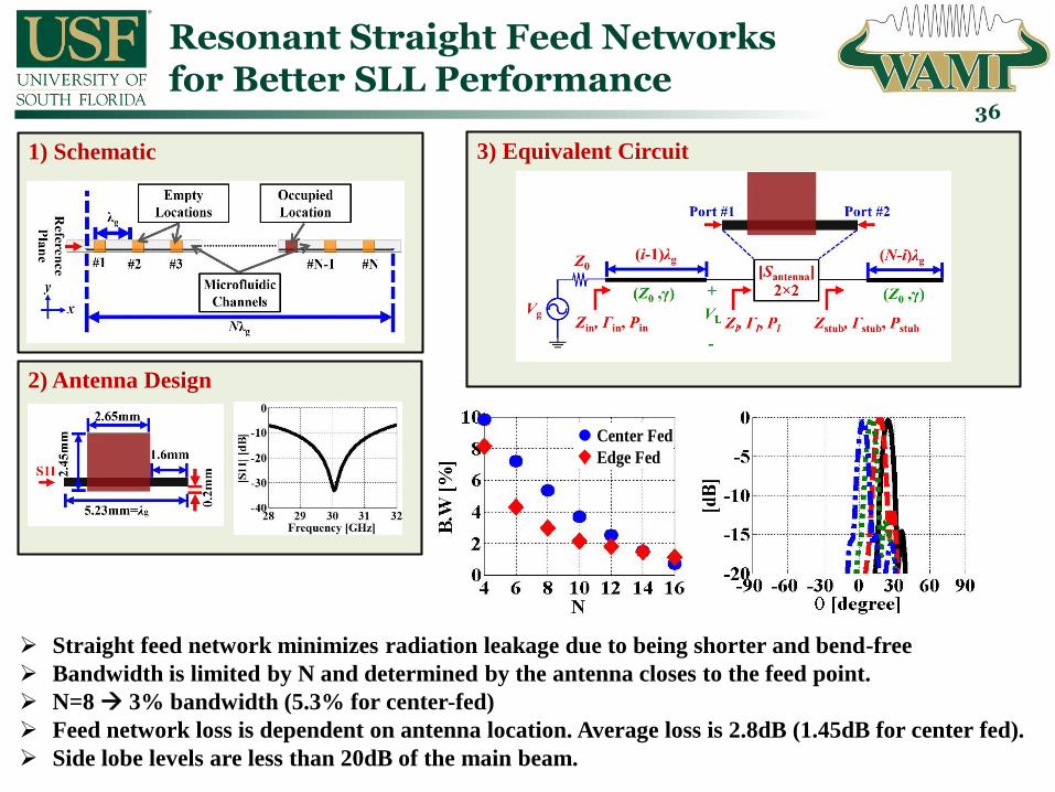
1) Schematic
Resonant Straight Feed Networks for Better SLL Performance
36
2) Antenna Design
3) Equivalent Circuit
Straight feed network minimizes radiation leakage due to being shorter and bend-free
Bandwidth is limited by N and determined by the antenna closes to the feed point.
N=8 3% bandwidth (5.3% for center-fed)
Feed network loss is dependent on antenna location. Average loss is 2.8dB (1.45dB for center fed).
Side lobe levels are less than 20dB of the main beam.
4 6 8 10 12 14 160
2
4
6
8
10
N
B.W
[%
]
Center Fed
Edge Fed
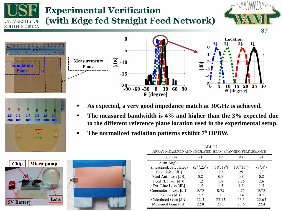
Experimental Verification (with Edge fed Straight Feed Network)
37
-90 -60 -30 0 30 60 90-20
-15
-10
-5
0
[degree]
[dB
]
0 5 10 15 20 25 30-5
-4
-3
-2
-1
0
[degree]-90 -60 -30 0 30 60 90
-20
-15
-10
-5
0
[degree]
[dB
]
Location4 3 2 1
As expected, a very good impedance match at 30GHz is achieved.
The measured bandwidth is 4% and higher than the 3% expected due
to the different reference plane location used in the experimental setup.
The normalized radiation patterns exhibit 70 HPBW.

Microfluidically Reconfigurable Selectively Metallized Plates:Switched Feed Networks
38
1) Switching Schematic
2) Microfluidic Switching Operation Via Selectively
Metallized Plate
To improve the bandwidth, loss
performance, and scanning speed of the
array; a selectively metalized plate approach
is employed to realize a switched feed
network
The required plate motion is reduced from
around 40mm to 4.2mm.
Having switches on the feed network
removes the need for resonances and
bandwidth becomes independent of array
size.

Experimental Verification of the Microfluidically Switched Transmission Line(publication pending)
39
Switch loss is near zero,
showing no difference
between a continuous
line and a switch line
when connectors are
taken into account.
Connector loss is at ~1
dB (0.5 dB per
connector).Fluid
IN/OUT
Fluid
IN/OUT

Microfluidically Switched Feed Network Operational Concept
40
0.6
mm
4.2
mm
𝝀𝒈/𝟐 𝝀𝒈/𝟐 𝝀𝒈/𝟐
0.8mm 1.8mm
O.C.
O.C.

2) Switched Array Bandwidth Performance
1) Feed Network Response
Microfluidically Switched Feed Network Performance
41
A very good impedance matching is achieved – suitable for larger arrays without bandwidth
compromise.
Insertion loss is <2 dB for the complete band (superior to other techniques).
The bandwidth depends on the antenna choice.
5%
6%
7%
8%
9%
1 2 3 4 5 6 7 8
BW
[%
]
Position
Feed Network
Loss

Fabricated Prototype and Characterization (Underway)(publication pending)
42
Array impedance is matched for different switch
positions (i.e. antenna excitations)
Larger S11 ripples in measurements are likely
due to connector – de-embedding is in progress.
Gain measurements are currently in progress.

Integrated Actuation with Piezoelectric Disks(publication pending)
43 MM-Wave devices (phase shifters, filters, and FPAs) require a small amount of metalized plate
displacement.
This motivates for integrating/packaging an actuation mechanism with the device.
Currently, we are investigating achieving actuation with piezoelectric disks – Initial experiment
is done for controlling resonance frequency of an X-band open loop resonator:
1) Piezo electric actuation on a microfluidic channel
Piezo disk actuator
BCB Bonding
Layer
APTES-Treated
LCP Membrane
Silver Epoxy
Microfluidic
Channel
PDMS Chip
Rogers RO6010Moving
Plate
Deflection
Voltage
AppliedDeflection
Increase
Voltage
Increased
Initial PositionPlate MovesFinal Position
2) Experimental Setup
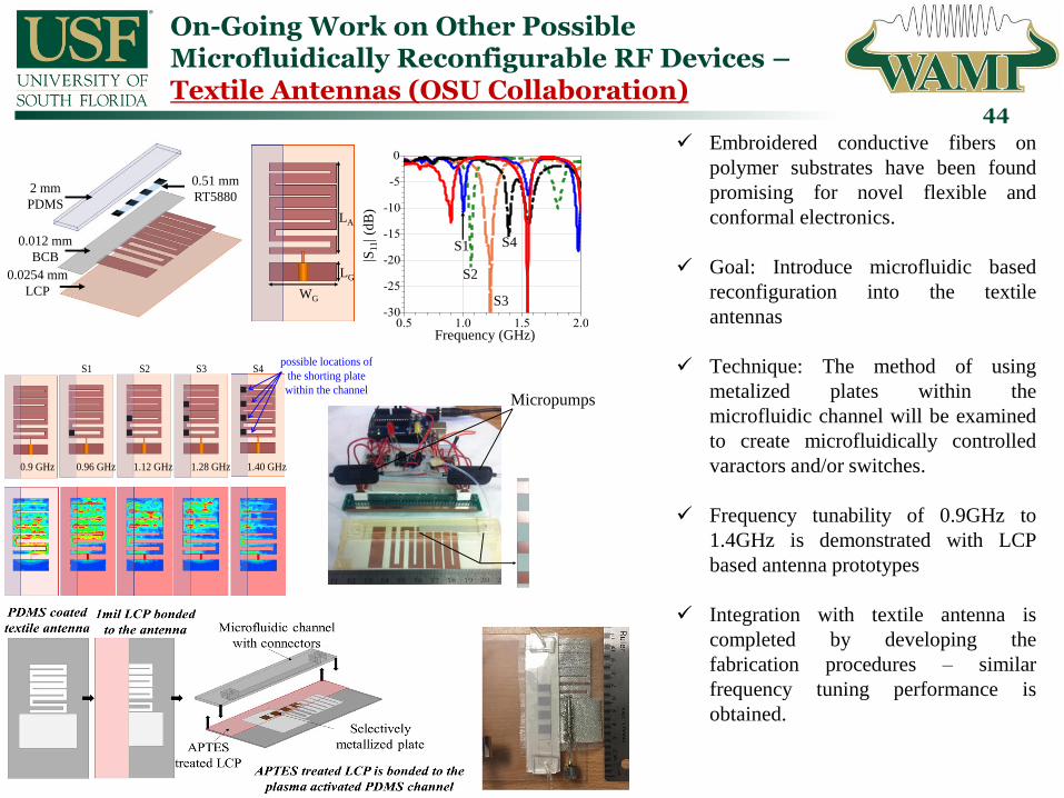
On-Going Work on Other Possible Microfluidically Reconfigurable RF Devices –Textile Antennas (OSU Collaboration)
44
0.0254 mm
LCP
0.012 mm
BCB
2 mm
PDMS
0.51 mm
RT5880
LG
WG
LA
0.9 GHz 0.96 GHz 1.12 GHz 1.28 GHz 1.40 GHz
S1 S2 S3 S4possible locations of
the shorting plate
within the channel
Frequency (GHz)
|S11| (d
B)
S1
S2
S3
S4
Micropumps
Embroidered conductive fibers on
polymer substrates have been found
promising for novel flexible and
conformal electronics.
Goal: Introduce microfluidic based
reconfiguration into the textile
antennas
Technique: The method of using
metalized plates within the
microfluidic channel will be examined
to create microfluidically controlled
varactors and/or switches.
Frequency tunability of 0.9GHz to
1.4GHz is demonstrated with LCP
based antenna prototypes
Integration with textile antenna is
completed by developing the
fabrication procedures – similar
frequency tuning performance is
obtained.

Concluding Remarks
45
Microfluidic Loading of RF devices with:
• Continuously movable metals (in liquid or solid form)
• Dielectric solutions
• Fluidic channels utilizing ultra-thin walls
offers new possibilities & degrees of freedom for RF design:• Miniaturization• Large frequency tuning range• High power handling• Low cost beam-steering• Low loss
Realized wideband frequency tunable monopole antennas with
high radiation efficiencies and high RF power handling
capabilities.
Introduced a new microfluidically controlled metalized plate
technique to alleviate reliability and low conductivity issues of
liquid metals.
Realized frequency-agile bandpass filters with 2:1 frequency
tuning range and high power handling capability.
Introduced a novel technique for low cost and efficient
realization of high gain mm-wave beam-scanning arrays.
Metallized
Areas
Liquid In
Liquid Out
RF In
RF Out
ZCl
ZPl
RP
w
RC
w
Microchannel
Zin
Roger 5880
plate

Journal Publications Related to the Presented Work
46
1. G. Mumcu, A. Dey, and T. Palomo, “Frequency-Agile Bandpass Filters Using Liquid Metal Tunable Broadside Coupled Split Ring
Resonators,” IEEE Microwave and Wireless Components Letters, vol. 23, no. 4, pp. 187 – 189, April 2013.
2. A. Gheethan, M. C. Jo, R. Guldiken, and G. Mumcu, “Microfluidic Based Ka-Band Beam Scanning Focal Plane Array,” IEEE
Antennas and Wireless Propagation Letters, vol. 12, pp. 1638 – 1641, 2013.
3. A. A. Gheethan, A. Dey, and G. Mumcu, “Passive Feed Network Designs for Microfluidic Beam-Scanning Focal Plane Arrays and
Their Performance Evaluation,” IEEE Transactions on Antennas and Propagation, vol. 63, no. 8, pp. 3452 – 3464, Aug. 2015.
4. A. Dey and G. Mumcu, “Microfluidically Controlled Frequency Tunable Monopole Antenna for High Power RF Applications,” IEEE
Antennas and Wireless Propagation Letters, vol. 15, pp. 226 – 229, 2016.
5. T. Palomo and G. Mumcu, “Microfluidically Reconfigurable Metallized Plate Loaded Frequency-Agile RF Bandpass Filters,” IEEE
Transactions on Microwave Theory and Techniques, vol.64, no.1, pp. 158 – 165, Jan. 2016.
6. A. Dey, R. Guldiken, and G. Mumcu, “Microfluidically Reconfigured Wideband Frequency Tunable Liquid Metal Monopole
Antenna,” IEEE Transactions on Antennas and Propagation, vol. 6, no. 6, pp. 2572 – 2576, June 2016.

Conference Publications & Presentations
47
1. A. Gheethan, R. Guldiken, and G. Mumcu, “Microfluidic Enabled Beam Scanning Focal Plane Arrays,” IEEE Antennas and Propagation
Society Symposium, pp. 1 – 4, Orlando, FL, USA, July 2013.
2. A. Dey, R. Guldiken, and G. Mumcu, “Wideband Frequency Tunable Liquid Metal Monopole Antenna,” IEEE Antennas and Propagation
Society Symposium, pp. 1 – 4, Orlando, FL, USA, July 2013 (student paper competition finalist – selected to be among the top 15 out of 141
competing papers).
3. A. Gheethan and G. Mumcu, “MM-Wave Beam Scanning Focal Plane Arrays Using Microfluidic Reconfiguration Techniques,” presented
in URSI - National Radio Science Meeting, Boulder, CO, USA, Jan. 2014.
4. T. Palomo and G. Mumcu, “Highly reconfigurable Bandpass Filters Using Microfluidically Controlled Metalized Glass Plates,” IEEE
International Microwave Symposium (IMS), pp. 1 – 3, Tampa, FL, USA, June 2014.
5. A. Gheethan and G. Mumcu, “2D Beam Scanning Focal Plane Arrays Using Microfluidic Reconfiguration Techniques,” IEEE Antennas
and Propagation Society Symposium, pp. 1 – 4, Memphis, TN, USA, July 2014 (student paper competition honorable mention – selected to
be among the top ~30 out of 149 competing papers).
6. A. Dey and G. Mumcu, “High Resolution Surface Imaging Arrays Interrogated with Microfluidically Controlled Metalized Plates,” IEEE
Antennas and Propagation Society Symposium, pp. 1 – 4, Memphis, TN, USA, July 2014.
7. A. Dey, A. Kiourti, G. Mumcu, and J. L. Volakis, “Microfluidically Reconfigured Frequency Tunable Dipole Antenna,” 9th European
Conference on Antennas and Propagation (EuCAP 2015), pp. 1 – 3, Lisbon, Portugal, Apr. 12–17, 2015.
8. A. Dey and G. Mumcu, “Microfluidically Controlled Metalized Plate Based Frequency Reconfigurable Monopole for High Power RF
applications,” IEEE Antennas and Propagation Society Symposium, pp. 1 – 4, Vancouver, BC, Canada, July 2015.
9. G. Mumcu, “Microfluidic Based High Gain Beam-Scanning Antenna Arrays for MM-Waves and Beyond,” presented in URSI - National
Radio Science Meeting, Boulder, CO, USA, Jan 2016 (invited).
10. A. Dey and G. Mumcu, “Small Microfluidically Tunable Top Loaded Monopole,” IEEE International Workshop on Antenna Technology
(IWAT), pp. 1 – 2, Cocoa Beach, FL, March 2016.
11. E. Gonzalez and G. Mumcu, “A Microfluidically Switched Feed Network for Beam-Scanning Focal Plane Arrays,” IEEE International
Workshop on Antenna Technology (IWAT), pp. 1 – 2, Cocoa Beach, FL, March 2016.
Conference Publications & Presentations (continued)
48
12. A. Dey and G. Mumcu, “Microfluidic Based High Resolution Microwave Imaging System,” IEEE Antennas and Propagation Society
Symposium, pp. 1 – 2, Fajardo, Puerto Rico, Jun. 26 – Jul. 1 2016.
13. E. Gonzalez and G. Mumcu, “Low-Loss Wideband Feed Networks for High Gain Microfluidic Beam-Scanning Focal Plane Arrays,” IEEE
Antennas and Propagation Society Symposium, pp. 1 – 2, Fajardo, Puerto Rico, Jun. 26 – Jul. 1 2016.
14. E. Gonzalez and G. Mumcu, “MM-Wave High Gain Beam-Scanning Focal Plane Arrays with Microfluidically Switched Feed Networks,”
URSI - National Radio Science Meeting, Boulder, CO, USA, Jan. 2017 (invited).
15. T. Palomo and G. Mumcu, “Frequency-Agile RF Filters Using Microfluidically Reconfigurable Selectively Metallized Plates,” IEEE Radio
and Wireless Symposium, Phoenix, AZ, USA, Jan. 2017 (invited).
![Compact Wideband Circularly Polarized SRR Loaded Slot ... · antenna based on SRR is designed in [10A dipole antenna ]. loaded with SRR [11] achieves wideband CP performance, but](https://img.dokumen.tips/doc/110x75/60ac0988b451332f6e3953f4/compact-wideband-circularly-polarized-srr-loaded-slot-antenna-based-on-srr-is.jpg)