Embed Size (px)
Citation preview

Medium-Voltage Components
No. AGS 531 691-01
Edition 08/2011
www.schneider-electric.com
IDISIntelligent Density Information System
Operation - ReplacementTechnical Instruction

Manufacturer:
Schneider Electric Sachsenwerk GmbH Rathenaustrasse 2 D-93055 Regensburg Germany ( +49 (0) 9 41 46 20-07 +49 (0) 9 41 46 20-418
Service:
Schneider Electric Sachsenwerk GmbH Rathenaustrasse 2 D-93055 Regensburg Germany ( +49 (0) 9 41 46 20-7777 +49 (0) 9 41 46 20-418

IDIS
3AGS 531 691-01 | Edition 08/2011
Contents
Remarks on this manual .............................................................................4Purpose and target group ........................................................................................... 4Reference documents ................................................................................................ 4Terms and symbols used ............................................................................................ 5Abbreviations used ..................................................................................................... 5Any questions or suggestions?................................................................................... 5
1 Safety provisions ..............................................................................6
2 Design and function ..........................................................................72.1 Positions of gas density switches and of the display unit in panels ................ 72.2 IDIS Monitoring System in GHA Switchgear Panels ....................................... 92.3 Technical data ............................................................................................... 102.4 Use in line with the intended purpose ........................................................... 102.5 Disposal after the end of the service life ....................................................... 10
3 Gas density switches ...................................................................... 11
4 IDIS display unit ..............................................................................124.1 Description .................................................................................................... 124.2 Display ranges .............................................................................................. 134.3 Function test (on commissioning) ................................................................. 144.4 Malfunction signals ........................................................................................ 144.5 List of remote monitoring signals .................................................................. 16
5 Replacement ....................................................................................175.1 Safety provisions ........................................................................................... 175.2 Replacement of the IDIS display unit ............................................................ 185.3 Replace gas density switch ........................................................................... 19
6 Replacement devices and accessories .........................................206.1 Auxiliary products .......................................................................................... 206.2 Gas density switch ........................................................................................ 206.3 Protective cap for gas connector socket ....................................................... 206.4 Versions of the display unit ........................................................................... 21

IDIS
4 AGS 531 691-01 | Edition 08/2011
As our products are subject to continuous further development, we reserve the right to make changes regarding standards, illustrations and technical data.All dimensions specified in this manual are in millimeters.
Purpose and target group
This Technical Manual describes operation and replacement of the Intelligent Den-sity Information System IDIS. It is exclusively intended for use by the manufacturer's staff or by persons certified for the IDIS system (training certificate).The work described in this manual may only be performed by specialist electricians with proven experience in conjunction with
■ the GHA series (training certificate) ■ all relevant safety provisions. ■ the IDIS system
This Technical Manual is an integral part of the product and must be stored so that it is readily accessible at all times for and can be used by persons who are to work on the switchgear. If the switchgear is relocated to another site, this Technical Manual must be passed on to the new operators along with the unit.This Technical Manual cannot describe every imaginable individual case or every customer-specific version of the product. For information which is not included in this manual, please contact the manufacturer.
Reference documents
■ purchase agreement containing the stipulations on the specific equipment of the switchgear and the legal details
■ the contract specific switchgearcircuit diagrams / documentation ■ assembly Instructions for GHA switchgear ■ operating Instructions for GHA switchgear ■ GHA switchgear system configuration
The following additional documents must be observed:
Remarks on this manual

IDIS
5AGS 531 691-01 | Edition 08/2011 5
Remarks on this manual
Terms and symbols used
This manual uses certain terms and symbols. They warn about dangers or provide important information which must be complied with at all costs so as to avoid danger and damage:
"Danger!" This danger symbol warns about dangerous electrical voltage. Contact with voltage may result in fatal injury!
"Warning!" This danger symbol warns about the risk of injury. Please comply with all the provisions identified by this symbol in order to avoid death or serious injury.
"Important:" This instruction symbol is used for information which is important to avoid material damage.
Abbreviations used
Ur: Rated voltageIr: Rated current
Any questions or suggestions?
Do you have any questions or suggestions regarding this manual, or do you require further information?We always strive to provide you with the best-possible information for optimum, safe use of our products. Thus, do not hesitate to contact us if you have any recommen-dations, amendments or proposals for improvement.

IDIS
6 AGS 531 691-01 | Edition 08/2011
1 Safety provisions
The work described in this manual may only be performed by specialist electricians with proven experience in conjunction with the IDIS system and the applicable safety provisions.Read the instructions carefully before you work on the switchgear.
■ Metal-enclosed AC switchgear for rated voltages > 1 kV up to including 52 kV:IEC 62271-200
■ Use and handling of sulphur hexafluoride (SF6) in high-voltage switchgear: IEC 62271-303
■ The locally applicable accident prevention, operating and work instructions must be complied with.
■ Installation: IEC 61936-1/HD 637 S11
■ Operation of electrical equipment: EN 50110-11
1 The national standards applicable in the country where the equipment is to be installed must be complied with.
Before performing work on the panels, it is essential that you comply with the follow-ing instructions:
Warning!Risk of injury from movable parts in mechanical drives. Before performing maintenance work,– isolate the system from the supply voltage,– release the circuit-breaker’s energy storing device by OFF–ON–OFF operation– switch ON via the make-proof earthing switch.
Warning!After the removal of covers from a switchgear, operator safety regarding internal arcs may be reduced unless the switchgear is isolated from the power supply. Optimum operator safety is only ensured if the switchgear is completely isolated from the power supply and earthed for assembly work.
Whenever the IDIS system issues a malfunction signal as described in Chapter 4, its reason must be ascertained on site immediately.During a malfunction signal, the insulating gas density is not monitored, and thus, the dielectric strength of the high-voltage components concerned is not monitored either.The behaviour in case of malfunctions and accidents is also described in the operat-ing manual for the series GHA.Make sure that first-aid measures are taken in case of injury to persons.Comply with the locally applicable accident and safety provisions.
Applicable standards and regulations:
Behaviour in case of incidents or accidents

IDIS
7AGS 531 691-01 | Edition 08/2011
2 Design and function
2.1 Positions of gas density switches and of the display unit in panels
The IDIS system consists of one up to max. three gas density switches and one display unit.
1
2
Fig. 1Branch-circuit panel
2
1
Fig. 2Bus section coupler
1
2
Fig. 3Branch-circuit panel
2
1
Fig. 4Bus coupler
Examples for GHA switchgear panels with single busbar1 gas density switches2 display unit
Double busbar1 gas density switches2 display unit
Definition for gas density switches in a panel with double busbar:Busbar 1 = rear busbarBusbar 2 = upper busbar
12
12
L R
Test I D I S
SS
LS
Test I D I S
SS re.
SS li.
LS
Test I D I S
SS1
SS2
LS
Test I D I S
SS 1
SS 2
LS

IDIS
8 AGS 531 691-01 | Edition 08/20118
2 Design and function
121
2
12
12
2
1
Fig. 5Bus section coupler of the upper bus-bar
2
1
Fig. 6Bus section coupler of the rear busbar
2
1
Fig. 7Busbar earthing switch
2
1
Fig. 8Double busbar metering panel with disconnectable busbar voltage trans-formers
Busbar attachments for double busbar1 gas density switches2 display unit
Definition for gas density switches in a panel with double busbar:Busbar 1 = rear busbarBusbar 2 = upper busbar
Test I D I S
MB
TB
Test I D I S
MB
TB
Test I D I S
SS re.
SS li.
LS
Test I D I S Test I D I S
SS re.
SS li.
LS
Test I D I S

IDIS
9AGS 531 691-01 | Edition 08/2011 9
2 Design and function
2.2 IDIS Monitoring System in GHA Switchgear Panels
Important:The rated pressure and the pick-up values of the IDIS system are indi-cated on the switchgear panel's nameplate and its Operating Manual.
Electrical bushing(gas-tight)
Gas connectorsocket
Circuit breakergascompartments
Busbar gascompartments
Gas density switch
IDIS display unit
Pressure reliefport
Fig. 9GHA switchgear with single busbar
Circuit breakergascompartments
Busbar 1 gascompartments(= rear busbar)
Busbar 2 gascompartments(= upper busbar)
Electrical bushing(gas-tight)
Gas connectorsocket
Gas density switch
IDIS display unit
Pressure reliefport
Fig. 10GHA switchgear with double busbar

IDIS
10 AGS 531 691-01 | Edition 08/201110
2 Design and function
2.3 Technical data
Ambient conditionsOperating temperature range -25°C up to +55°C
Temperature range for stor-age and transport -40°C up to +70°C
Auxiliary supply/ power consumptionAuxiliary voltage 24 V DC, admissible fluctuation range ± 20%, with
polarity-reversal protectionmax. power consumption 150 mA
Contact data of signalling relaysRated power (resistive) 5 A / 250 V AC
5 A / 30 V DCmax. switching capacity 1250 VA / 150 Wmax. switching voltage 250 V AC / 220 V DCmax. DC load (resistive) 0,4 A / 220 V DC
Requirements/standards
Insulation strengthAlternating Voltage acc. to IEC 60255-5, test
value 2 kV
Impulse voltage acc. to IEC 60255-5, class 3, test value 5 kV
EMC requirements acc. to IEC 61000Mechanical requirements Resistance to earthquakes in accordance with EN
60255Operating conditions normal service conditions in acc. to IEC62271-1,
temperature class "minus 25 °C indoor"
2.4 Use in line with the intended purpose
The Intelligent Gas Density Information System IDIS is exclusively intended to moni-tor gas-insulated medium-voltage switchgear units. It may only be used in the scope of the specified standards and the switchgear-specific technical data. Any other utilization constitutes improper use and may result in dangers and damage.
The manufacturer shall not be held responsible for damage which occurs if ■ instructions in this technical manual are not complied with, ■ the IDIS system is not operated appropriately (see above), ■ the IDIS system is assembled, connected or operated improperly, ■ accessories or spare parts are used which have not been approved by the
manufacturer, ■ the IDIS system is converted without the manufacturer's approval, or if inadmis-
sible parts are attached.
2.5 Disposal after the end of the service life
The disposal of the components of the IDIS system is described in the scope of the disposal of the switchgear panel pertaining to it.Disposal at the end of the service life is performed as a service by the Service Center at the manufacturer's which is subject to a fee.
Disclaimer of liability

IDIS
11AGS 531 691-01 | Edition 08/2011
3 Gas density switches
The gas density switches are screwfastened to the gas connector sockets of the appropriate cladded compartments (Fig. 11). They can be replaced at any time. The gas density switches are temperature-compensated. If the insulating gas temperature changes, the output value remains constant, as a temperature change does not change the insulating gas density.
The gas density switch features two NO contacts. The NO contacts define two response thresholds which trans-mit three differentiated messages to the IDIS display unit, depending on the switch condition (Fig. 12).
Gas density switchesIDIS display unit
Remotesignalling
P1
P2
P3Gas
-fille
d co
mpa
rtmen
ts
1
3
2
1. warninglevel
2. warninglevel
Fig. 12IDIS schematic diagram
31 2 4
Fig. 111 Gas density switch 2 Connection cable to display unit3 Swivel nut4 Gas connector socket

IDIS
12 AGS 531 691-01 | Edition 08/2011
4 IDIS display unit
4.1 Description
The temperature-compensated gas density information system IDIS represents the signals of the max. 3 gas density switches connected in terms of colour-coded LEDs.Remote signalling relays on the back enable signals to be transmitted to a remote control or I&C system.The display unit evaluates the signals of each gas density switch and indicates the insulating gas states "ready to operate", "1 warning level" and "2. warning level" via three LED per channel.A status change must be present constantly for at least three seconds before the input is evaluated (signal debounce).
2
1
3
45
6
7
8
9
Fig. 13IDIS display unit, showing for example a circuit-breaker panel with single busbar; variants see chapter 6.4, page 211 Nameplate2 Schematic diagram3 Colour LED ready for operation4 Colour LED 1 warning level5 Colour LED 2 warning level6 Monitoring of busbar compartment7 non-activated channel8 Monitoring of circuit-breaker compartment9 Function test push-button

IDIS
13AGS 531 691-01 | Edition 08/2011 13
4 IDIS display unit
4.2 Display ranges
The table below shows the three possible insulating gas states which can be represented by the indicator unit for each active channel. The data is referred to a compartment monitored by a gas density switch.
Warning!For reasons of operator safety, covers must not be removed dur-ing operation. Refer to the safety provisions in section 1.
Important: ■ The rated pressure and the 1. warning level of the IDIS system
are indicated on the switchgear panel's nameplate. ■ Always comply with the operating manual of the switchgear.
For use and handling of sulphur hexafluoride (SF6) in high-voltage switchgear, IEC 62271-303 must be complied with.
LED display StateState of re-mote signal-ling relays
Actions to be taken
grünready for operation
Both remote signalling re-lays picked up
–
gelb 1. warning level in case of pressure drop
Remote signal-ling relay "1st warning level" dropped, "2nd warning level" remains picked-up
■ Contact Service-Center ■ Replenish insulating
gas1 and watch the sys-tem to find out if the 1. warning level reoccurs
■ Schedule a disconnec-tion of the compartment in question
rot 2. warning level in case of pressure drop
Remote signal-ling relay "2nd warning level" dropped, "1st warning level" is picked up again
■ Contact Service-Center ■ Isolate the correspond-
ing compartment from power supply
1Warning!Insulating gas may only be refilled by trained specialist staff. Comply with the valid safety instructions and data sheets.
Messages of the IDIS display unit per channel / actions to be taken in case of a loss of density (within the compartment)

IDIS
14 AGS 531 691-01 | Edition 08/201114
4 IDISdisplayunit
4.3 Functiontest(oncommissioning)
Warning!High voltage must not be connected until the function test has been performed successfully, as the the insulating gas monitoring is not ensured.
1. Use a pointed object (e.g. pen) to press the push-button in the opening on the front labelled "Test" (Fig. 4.5). Now all LEDs of the active channels must go on. Both remote signalling relays must drop out at the same time and issue the 1. warning level and the 2. warning level.
2. Release the button; the IDIS sys-tem returns to its normal operation.
1. Do not commission the panel!2. Replace display unit (see section
5).
4.4 Malfunctionsignals
Malfunction signals have priority over loss-of-density signals if both are present simultaneously.
Warning!As long as malfunction signals are active, high voltage must not be connected on commissioning due to the fact that there is no insulating gas monitoring. The insulating gas monitoring is not ensured while a malfunction signal is on.
Important:During all malfunction signals of the IDIS system, both remote signal-ling relays at the display unit are, on principle, in drop-out status and issue the signals pre-alarm and main alarm at the same time.
Action:The reason for the malfunction signal must be clarified immediately on site based on the LEDs.
Warning!Refer to the safety provisions in section 1.
Test I D I S<<<
Push-button for function test
Fig. 14Function test: All active LED must go on and the remote signalling relays is-sue pre-alarm and main alarm.
Actionstobetakenincaseofmalfunctions:
Specificitiesforremotemonitoring:

IDIS
15AGS 531 691-01 | Edition 08/2011 15
4 IDIS display unit
The IDIS system performs a selfdiagnosisat intervals of 25 seconds. If a fault is detected the yellow and the red LEDs on all active channels are lit (Fig. 15). Both remote signalling relays drop out.Action:Replace display unit (see section 5).
Due to the closed-circuit principle, the lines to the gas density switches are monitored. If a connection cable is interrupted, the yellow and the red LEDs of the channel in question flash (Fig. 4.3). Both remote signalling relays drop out. (Fig. 16). Actions:1. Check the connection cable /
plug-in contacts to the gas density switch (see section 5).
2. If necessary, check the gas density switch and the gas density of the compartment in question (Contact the manufacturer).
As long as there is no supply voltage present, all LEDs on the display unit are inactive (Fig. 17). Both remote signalling relays drop out.Actions:1. Apply supply voltage.2. Check contacts and supply cable.
Inform the manufacturer.
Display unit:
Test I D I S<<<
Fig. 15All active yellow and red LEDs are lit:System alarm
Test I D I S<<<
Fig. 16In the lower channel, the yellow and thered LED flash: Check the connection cable for the appropriate gas densityswitch - in this case the circuit-breakercompartment.
Line monitoring to the gas density switches
Test I D I S<<<
Fig. 17None of the LEDs is lit. The power sup-plyis not available.
Supply voltage not available

IDIS
16 AGS 531 691-01 | Edition 08/201116
4 IDIS display unit
4.5 List of remote monitoring signals
A total of five different states of the IDIS system are retransmitted via the two remote signalling contacts.
Important:Whenever the IDIS system issues an alarm and malfunction signal, its reason must be ascertained on site immediately.
Remote signals from the IDIS system
State of the two remote signal-ling relays
Actions
Operative Both relays are picked up ―
Pre-alarm (Insulating gas density)
Relay "pre-alarm" dropped out ("Main alarm" remains picked up)
see chapter 4.2, page 13
Main alarm (Insulating gas density)
Relay "Main alarm" is dropped out and "pre-alarm" picks up again.
see chapter 4.2, page 13
Malfunction signal Both relays are dropped out see chapter 4.4, page 14
Function test Both relays must drop out see chapter 4.4, page 14

IDIS
17AGS 531 691-01 | Edition 08/2011
5 Replacement
5.1 Safety provisions
IDIS units may only be replaced by specialist electricians with proven experience in conjunction with the IDIS system and the applicable safety provisions.
Danger!Prior to performing work in the area of the panel drives, switch the supply voltage OFF and make sure to prevent reclosure.
Warning!Risk of injuries while working in the area of the drives. Before commencing work, release the circuit-breaker’s energy storing device by performing the sequence of operations OFF-ON-OFF.
Warning!Loss of insulating gas causes a risk of internal faults within the compartment, as there is no insulation strength. Do not open the gas tanks!
Warning!After the removal of covers from switchgear, operator safety regarding internal faults may be impaired unless the switchgear is isolated from the power supply. Optimum operator safety is only ensured if the switchgear is completely disconnected from the power supply and earthed during assembly.
These replacement instructions describe exclusively the disassembly and assembly of the gas density switch and the display unit.To have access to the devices, covers may have to be removed or dismounted, depending on the panel types and variant.

IDIS
18 AGS 531 691-01 | Edition 08/201118
5 Replacement
5.2 Replacement of the IDIS display unit
5
4 3
1 2
Fig. 18Assignment of rear socket contacts on the display unit. Shown: double busbar feeder panel (Exception: bus section coupler)1 Remote signalling contacts2 Power supply terminal
Connectors for gas density switch:3 Busbar 1 compartment4 Busbar 2 compartment5 Circuit-breaker compartment
1. The operating panel in which the IDIS display unit has been mounted should be removed depending on the ease of access. Observe the assembly instructions of the switchgear panel!
2. Remove the connectors for remote signalling, power supply and the gas density switch.
3. Press both retaining clips outwards and remove display unit to the rear (Fig. 19).
1. Place both retaining clips in the sheet-metal cut-out and press them outwards slightly. Push the display unit in the sheet-metal cut-out from the rear, until the retaining clips are engaged in the display unit (Fig. 20).
2. Reconnect the connector for re-mote signalling, power supply and the gas density switch according to the socket contact assignment (Fig. 18, page 18).
3. Check the display unit for proper working order (see chapter 4.3).
4. Remount the covers which were removed previously.
1
1
2
Fig. 19Press retaining clips to the side (1) andpull IDIS device out (2)
Removal
Assembly
1
1
2
Fig. 20Press clip outwards (1) and push IDISdevice inwards until it locks in (2)

IDIS
19AGS 531 691-01 | Edition 08/2011 19
5 Replacement
5.3 Replace gas density switch
Warning!Risk of leakage: When removing and remounting the gas density switch, the gas connector socket must be held up (locked; wrench size 32).
1. Remove the three-pole connector of the gas density switch from the display unit and pull connection cable back to the gas density switch.
2. Release swivel nut (wrench size 32) between the gas density switch and the gas connector socket.
3. Pull the gas density switch off (Fig. 21). At the same time, the valve of the gas connector socket is closed automatically.
4. Should no replacement unit be available during disassembly, the gas connector socket must be closed by means of a cap (Fig. 22)
31 2 4
Fig. 211 Gas density switch 2 Connection cable to display unit3 Swivel nut4 Gas connector socket
Fig. 22CapRef.-No.: AGS C05269-01
1. Remove cap (Fig. 22) from the gas connector socket.2. Coat seal and sealing surfaces (required auxiliary products, see Chapter 6.1,
page 20). – Sealing surfaces, seals (cord sealing rings) and grooves for cord sealing
rings must be cleaned with particular care using a cleaning agent and a lint-free cloth.
– Immediately afterwards, apply SF6 multi-purpose lubricant using a nylon brush or a leather cloth which is exclusively reserved for this application; then keep the brush or the leather cloth in a place where it is protected against soiling.
Important:Sealing surfaces coated with SF6 multi-purpose lubricant must no longer be touched. Any contamination may impair function (leakage).
3. Push gas density switch into the gas connector socket and secure it using the swivel nut (Fig. 5.4). Tightening torque: 15 + 5 Nm
4. Route connecting cable to the IDIS display unit and - if necessary - fasten it to the panel; reel up excessive cable lengths.
5. Connect the three-pole connector of the gas density switch to the appropriate socket contact.
6. Perform a functional check on the display unit and check malfunction signals (see Chapter 4.3 and 4.4).
7. Remount the panel shutters which have been removed previously.
Assembly

IDIS
20 AGS 531 691-01 | Edition 08/2011
6 Replacement devices and accessories
6.1 Auxiliary products
Warning!Risk of injury if these products are handled improperly. Observe the safety data sheets of the manufacturers of the auxiliary prod-ucts.
Only the following auxiliary products may be used, which can be purchased from the manufacturer. The use of other auxiliary products is not admissible.
Designation Ref. No.SF6 multi-purpose lubricant MS, 0.75 kg can ST312-109-847
Detergent (ethanol, type 641) S 009 002
Please enquire at the manufacturer’s regarding the available packing unit.
6.2 Gas density switch
Rated pressure pre 1
Ref. No.
0,03 MPa AGS 002908-03
0,05 MPa AGS 002908-010,06 MPa AGS 002908-02
1 The rated pressure of the panel is indicated on its nameplate. The speci-fied pressure data refer to +20°C and an atmospheric pressure of 101.3 kPa absolute.
Fig. 23Gas density switch with signal line
6.3 Protective cap for gas connector socket
Ref. No.: AG C052690
Fig. 24Cap with packing ring

IDIS
21AGS 531 691-01 | Edition 08/2011 21
6 Replacement devices and accessories
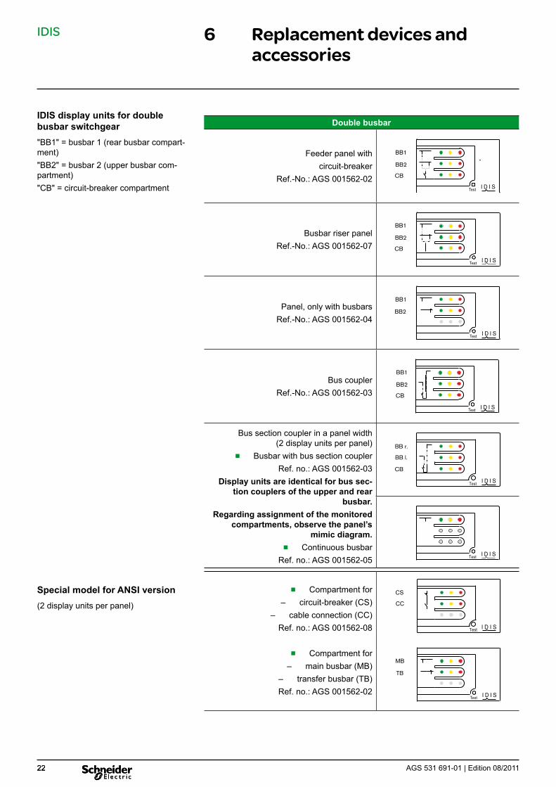
6.4 Versions of the display unit
Depending on the design of the switchgear panels, panel-specific IDIS display units are used.The design in question depends on the panel configuration and can be identified by means of the schematic diagram on the IDIS display unit.
Important:Other customized busbar designations must be taken into considera-tion analogously.
Single busbar
Feeder panel withcircuit-breaker
Ref.-No.: AGS 001562-01Test I D I S
BB
CB
Busbar riser panelRef.-No.: AGS 001562-06
Test I D I S
BB
CB
Panel, only with busbarRef.-No.: AGS 001562-05
Test I D I S
BB
Bus section couplerRef.-No.: AGS 001562-03
Test I D I S
BB r.
BB l.
CB
IDIS display units for single busbar switchgear"BB" = busbar compartment"CB" = circuit-breaker compartment
IDIS
22 AGS 531 691-01 | Edition 08/201122
6 Replacement devices and accessories
Double busbar
Feeder panel withcircuit-breaker
Ref.-No.: AGS 001562-02Test I D I S
BB1
BB2
CB
Busbar riser panelRef.-No.: AGS 001562-07
Test I D I S
BB1
BB2
CB
Panel, only with busbarsRef.-No.: AGS 001562-04
Test I D I S
BB1
BB2
Bus couplerRef.-No.: AGS 001562-03
Test I D I S
BB1
BB2
CB
Bus section coupler in a panel width (2 display units per panel)
■ Busbar with bus section couplerRef. no.: AGS 001562-03
Display units are identical for bus sec-tion couplers of the upper and rear
busbar.Regarding assignment of the monitored
compartments, observe the panel’s mimic diagram.
■ Continuous busbarRef. no.: AGS 001562-05
Test I D I S
BB r.
BB l.
CB
Test I D I S
■ Compartment for
– circuit-breaker (CS) – cable connection (CC)Ref. no.: AGS 001562-08
■ Compartment for
– main busbar (MB) – transfer busbar (TB)
Ref. no.: AGS 001562-02
Test I D I S
CS
CCLS
Test I D I S
MB
TB
IDIS display units for double busbar switchgear"BB1" = busbar 1 (rear busbar compart-ment) "BB2" = busbar 2 (upper busbar com-partment) "CB" = circuit-breaker compartment
Special model for ANSI version(2 display units per panel)


Schneider Electric35, rue Joseph MonierCS 3032392506 Rueil-Malmaison Cedex, France
RCS Nanterre 954 503 439Capital social 896 313 776 €www.schneider-electric.com AGS 531 691-01 | 08/2011
As our products are subject to continuous development, we reserve theright to make changes regarding the standards, illustrations and technicaldata described in this Technical Manual. For any requests, please contact the address given below.
Schneider Electric Sachsenwerk GmbHRathenaustrasse 2D-93055 Regensburg, Germany( +49 (0) 9 41 46 20-07 +49 (0) 9 41 46 20-418
© S
chne
ider
Ele
ctric
201
1 –
All
right
s re
serv
ed to
this
tech
nica
l man
ual.
Rep
rodu
ctio
n an
d m
akin
g av
aila
ble
of th
is te
chni
cal m
anua
l, or
ext
ract
s, to
third
par
ties
are
proh
ibite
d.
Onl
y in
tegr
al re
prod
uctio
n of
this
tech
nica
l man
ual i
s pe
rmitt
ed w
ith th
e w
ritte
n pe
rmis
sion
from
Sch
neid
er E
lect
ric. E
lect
roni
c co
pies
in e
.g. P
DF-
form
at o
r sca
nned
ver
sion
ha
ve th
e st
atus
“for
info
rmat
ion
only
” . T
he o
nly
valid
ver
sion
of t
his
tech
nica
l man
ual i
s al
way
s en
clos
ed d
irect
ly to
the
prod
uct i
n qu
estio
n by
the
fact
ory.