Embed Size (px)
Citation preview
м Design & Construction Guidelines Florida Gulf Coast University
MECHANICAL UTILITIES AND EQUIPMENT
GENERAL MECHANICAL GUIDELINES Utility work and connections to University utility systems must be properly planned to prevent disruption of classes and/or research efforts. All utility work shall be coordinated with the University Physical Plant Department. Each drawing that shows a connection to existing utilities must have a note that states that the Contractor shall request permission for all outages as far as possible in advance. This shall be a minimum of 14 days except in case of emergency. It shall be noted that even with the advance notice, it will not always be possible to grant the requested time and date, as classes and research must have precedence. Permission must be obtained, through the Director of Physical Plant or designee. Explicit details must be shown for all connections to existing utilities.
1. It shall be the responsibility of the A/E to investigate and determine the actual location of all
underground utilities including mechanical, electrical and plumbing or obstructions at the building site before beginning design work and while carrying out renovations. The University will provide all available information as appropriate.
2. The contractor shall pay for utilities during construction. The contractor shall contract with Lee
County Utilities whenever possible. If it is necessary to have construction utilities supplied from the University, the contractor shall install temporary services in accordance with local codes. The University will bill the contractor monthly for utilities used. Shall the University wish to make an exception the A/E will be so informed.
3. Heat, air conditioning, humidity control and any other environmental factors shall be the responsibility of the contractor throughout the construction period.
4. All utilities are to be metered for each building, including water and chilled water. All utility
metering must be coordinated with the University Physical Plant Department prior to construction. All metering devices must have the capability to report to the Campus Energy Management System. If the building contains Auxiliary occupants in addition to E&G occupants, separate metering must be provided for each Auxiliary occupant.
5. Provide separation of mechanical equipment and other noisy areas from academic and office areas.
6. Care shall be taken in the placement of all outdoor air inlets to ensure that odors and other pollutants (automobile exhaust, generator exhaust, fume hood exhaust, etc.) do not enter the building.
7. Mechanical rooms must have adequate openings to facilitate the removal and replacement of major pieces of equipment. Provide double 3'-0" doors which swing outward, with active/inactive leafs.
8. There must be adequate space in mechanical rooms to provide ample access space around all equipment for routine maintenance items and procedures, such as filter replacement, lubrication, and so on.
9. Pipe insulation thickness to be per latest energy efficiency standards.
2 Design & Construction Guidelines Florida Gulf Coast University
10. Access to electrical rooms, mechanical rooms, elevator machine rooms, fan rooms, pump rooms, etc., shall not be through other rooms. It is preferred that access to these spaces be achieved from a main corridor and/or exterior space. Access shall not be by ladders. Where possible, penthouse rooms shall have elevator access.
11. Mechanical Rooms and similar spaces are not to contain storage areas. All power disconnects to equipment shall be so located as to be easily accessed per code.
12. All piping shall be color coded and labeled as to use. Verify requested colors with the Director of Physical Plant or designee.
13. All (building exhaust, lab, etc.) fans shall be labeled as to use, area served and power source.
14. All HVAC controls shall be of the direct digital type/NAE via BACNET. See Appendix P.
15. All hydronic systems shall have adequate air eliminators installed.
16. Provide MERV 9 air filtration on all central-station air handling units.
17. Manhole and valve box design shall be carefully coordinated with the University Physical Plant
Director or designee.
18. All piping utilized for underground piping are required to have the ends sealed prior to storage or use on site. No end seals shall be removed until the end in question is actually ready for welding or otherwise connecting. In no event shall any piping be left in a trench with an open end at any time. This requirement shall be strictly enforced.
19. Systems Test & Balance will be provided through the Physical Plant Department as an additional service but shall be paid form the project budget. The specifications will require the contractor to participate in the testing, make any changes necessary and pay for any re-testing that may be required to make the systems meet specifications.
20. All air handling unit condensate drain pans must drain to the storm sewer system, with a by-pass to the floor drains when using chemicals to clean coils. Contact the Director of the Physical Plant Department.
21. Mechanical rooms shall not be utilized as return air plenums.
22. Mechanical rooms that generate heat such as pump rooms shall be cooled using a thermostatically controlled forced air ventilation system utilizing outdoor air. Wherever possible, intake air shall be directed into the pump room and removed from the steam room. Approval of an alternative cooling scheme shall be approved by the Director of the Physical Plant Department.
23. All mechanical equipment such as air handlers, pumps, exhaust fans, etc., shall be referred to and labeled by building then floor, i.e., EF5-1 would be Academic Building 5 exhaust fan number one.
24. Identification signage systems and markings for all mechanical equipment and piping shall be
required.
3 Design & Construction Guidelines Florida Gulf Coast University
PLUMBING GUIDELINES 1. Lee County Utilities (LCU) will furnish water meters and taps for domestic and fire water. All tap fees
and system charges shall be paid for by the Contractor. Install water meters and domestic water backflow preventer above grade and provide insulated cover. Install backflow preventers in accordance with LCU. Contact LCU for their requirements and information. LCU’s approval for all proposed connections must be received prior to completion of the 100% documents. Written proof of LCU’s approval must be provided to the Utilities Section prior to bidding the project.
2. Below grade, all domestic cold water piping exterior to building shall be ductile iron or PVC. Underneath buildings, piping shall be type K copper or ductile iron. All domestic water piping inside the building and above grade shall be type L copper, except for high purity water. Materials for high purity water systems shall be coordinated with the University Project Manager. No CPVC.
3. Fire water system connections shall be compatible with the San Carlos Fire Department fittings.
Contact them for information.
4. Provide shut off valves at least at each floor level for all utilities. Toilets, urinals, sinks and water coolers shall have individual shut-off valves. Provide access panels (minimum 36” x 36”) with the appropriate fire ratings for maintenance and repair activities.
5. Floor drains are to be provided in all toilet rooms, custodial closets and mechanical rooms.
6. All piping, chilled water and air handler unit system strainers shall be equipped with valves for blow down cleaning.
7. Hose bibs shall be provided in toilet rooms located underneath the sink, machinery rooms and at 100- foot intervals in exterior areas for maintenance use.
8. Teflon containing joint sealer shall be utilized in all screwed piping installations.
9. All piping shall be color coded and labeled as to use and flow direction.
10. All exterior chilled water valves shall be fitted with a complete one-piece valve box unit constructed of concrete, steel or fiberglass. The box shall have a hinged cover and be set in concrete. The installation shall be such to support small vehicle and lawn maintenance equipment.
11. Fire suppression systems shall be installed, tested and certified per appropriate NFPA and State Fire Marshal requirements.
12. Urinals shall be of the flooded open throat type to avoid stoppages and odor problems. Urinals shall be provided with automatic flushing sensors. Urinals shall be designed for 1/8 gallon per flush (LEED).
13. Floor drains, where necessary, are to be placed at the lowest point in the area and shall be provided in all restrooms, custodial closets, mechanical rooms, storage rooms, etc.
14. Lavatory faucets shall be the types that will not flow over .5 GPM and provided with manual sensors. Timed shut off valves shall be used.
4 Design & Construction Guidelines Florida Gulf Coast University
15. Standard type washbasin shall have strainer type drain, lever handles equipped for handicapped use, cold water faucets, no hot water faucets (except in dormitories and service buildings) and soap dispensers.
16. Water Closets shall be wall mounted and designed for a maximum of 0.8 gallons per flush. (LEED) 17. Custodial closet faucets shall be single delivery mixing type with hot and cold water and have
threaded spout equipped with a vacuum breaker and a three-foot hose. Place faucets 30" - 36" above sink rim. No tempered water.
18. Emergency eyewash equipment shall be plumbed to a drain.
19. No cleanouts in ceiling. WATER BASED FIRE EXTINGUISHING SYSTEMS 1. The contractor shall furnish all labor and equipment for the complete installation of a water based
fire-extinguishing system and shall be the installing contractor or site representative with the required license. No subcontracting will be allowed. The contractor must be NICET level III certified and must possess the appropriate class I or class II fire sprinkler license as required by the State of Florida.
2. Fire water based systems shall be installed, inspected, tested and certified per appropriate NFPA 13, 14, 20, 24, 25, including NFPA 101. Any applicable codes shall apply to meet State of Florida and Fire Marshal requirements, local and state jurisdiction.
3. The fire system contractor shall be responsible for equipment, materials and workmanship of the system for one year. The warranty shall be enforced 24 hours a day, seven days a week including weekends and holidays during this period of time. The contractor will also respond after being advised of his responsibility and the nature and/or condition of the equipment that has failed by the FGCU Fire Systems on-call technician. After notification has been made to the responsible equipment contractor, a minimum of one hour will be allowed to respond and arrive on site. When the problem has been secured or corrected to the satisfaction of the technician o the FGCU Police Department will be notified.
4. The installation of fire water mains shall included backflow preventers in accordance with NFPA requirements including City Ordinance. Contact them for their requirements and information. All fire mains and/or valves shall be painted and labeled to indicate the proper building name controls. The City must approve all connections to the City water mains. The City’s approval must be received prior to completion of the 100% documents. Written proof of the City’s approval must be provided to the Utilities Section prior to bidding the project.
5. Fire water system connections and fittings shall be compatible with the San Carlos Fire Department fittings. Contact them for information.
6. Provide six extra Escutcheon Plates of each type installed on any system, installer will provide manufacturer name and address, supplier name and address and parts number.
5 Design & Construction Guidelines Florida Gulf Coast University
7. The main drains and inspectors test drains be pipe to an adequate drain or outside the building. When piped outside the drain shall not affect the architectural design and landscaping of the building. When piped outside the building, the water flow shall not pose a threat to persons on sidewalks or streets adjacent to the building.
8. Provide 3-1/2" gauges with a connection not smaller than 1/4", and each gauge connection equipped with a shutoff valve and provisions for draining.
9. All control, drain and test connection valves shall be provided with permanently marked weatherproof metal or rigid plastic identification signs. The sign shall be secured with corrosion resistant wire, chain or other approved means.
10. All control valves will have proper signage to indicate the areas of coverage. This will start from the feed supply into the building through all branch lines.
11. On any fire pump installation, the use of PVC and/or plastic pipe, fittings, or components will not be acceptable.
CENTRAL ENERGY PLANT (CEP) CENTRAL CHILLED WATER SYSTEM/BUILDING INTERFACES 1. The following are requirements for new building designs in order to best produce the most efficient
utilization of the CEP system, utility distribution system, and the building.
2. The CEP was designed as a variable flow/tertiary system to achieve maximum energy economics. The design of the building shall be such as to operate over a varying pressure range.
3. The interface between the building and the Central Chilled Water Distribution System will insure the chilled water temperature difference will equal to or exceed 14 degrees while satisfying the building design criteria. The interface will also insure that the building pump(s) and the distribution pump(s) will be completely decoupled. The Utilities Section will provide design and material requirements for the interface.
4. The CEP is operated to produce 42 to 48 degrees F. chilled water depending on overall system needs and energy conservation measures being utilized. The design professional shall verify this strategy with the project manager before design begins.
5. Existing pressures leaving the CEP vary from 35 to 85 psig. Be aware that the maximum operating pressure for the existing chilled water underground piping is 100 psig. Any additions to this system shall be designed for 150 psig.
6. All major air handling unit coils shall be designed for not less than 12 degrees Fahrenheit
temperature rise, and be provided with two way control valving. AIR CONDITIONING 1. Utilize the campus chilled water system for cooling if at all possible. The interface between the
system and building is discussed later. A fine mesh monel or stainless steel strainer shall be installed in the chilled water supply line of each building to prevent contamination of the building chilled
6 Design & Construction Guidelines Florida Gulf Coast University
water system. All chilled water strainers shall have a pressure gauge installed across the strainer so as to quickly determine when strainers are dirty.
2. When the air conditioning system cannot be connected to the Central Chilled Water System, consider the use of water cooled condenser(s) utilizing a deep well water supply with injection return. Utilize existing wells as practical. New well pumps shall be mounted above ground with a suitable enclosure. Provide water lubrication. Cooling towers are not desired by the University. The existing Northwest Florida Water Management District Consumptive Use Permit will have to be amended if a new well is to be installed. Be aware that Leon County has a Wellhead Protective Ordinance that also will have to be complied with. All cooling well design and permitting must be coordinated with the Utilities Section.
3. All air conditioning condensate lines shall be of insulated type "L" copper or approved equal. Provide insulation details to insure vapor proof covering.
4. If condensation occurs on the outside of insulated ducts, HVAC equipment, VAV boxes, flex ducts, piping, etc. during the construction period, the Project Team shall take immediate action to determine the reasons, and initiate corrective action. Substantial Completion shall not be approved until corrections are agreed to in writing. The contractor shall be required to rework the insulation until satisfactory if condensation occurs on any cold surface at any time during the warranty period.
5. All chilled water taps into the Central Chilled Water System shall be made without system interruption, where feasible. Each juncture shall be provided with a shut off valve and valve box for easy access. Note that most of the Central Chilled Water System piping is constructed of asbestos bearing material, i.e. Transite. "Hot tapping" details will be provided by the University. All chilled water connections, whether external or internal, must be coordinated with and approved by the Utilities Section. Initial coordination concerning the approved location of new connections must be done prior to completion of the Schematic Design Phase.
6. Exterior steel piping shall be schedule 40 black steel with welded joints. The use of pre-insulated black steel pipe is permissible. Contact Director of the Physical Plant Department for currently approved types and manufacturers.
7. Insulation for chilled water piping above grade shall consist of foamglas that is covered with a .016 inch thick aluminum weatherproof jacket that has a factory applied integral vapor barrier. The foamglas shall be glued to the piping. Fasten with aluminum bands located not more than 12 inches apart. Insulation below grade shall be foamglas with Pittwrap cover.
8. All building chilled water systems served from central chilled water shall be designed to have variable flow characteristics compatible with the central system.
9. All chilled water piping shall be installed with shut-off valves at each floor and at each AHU.
10. All major air handling unit coils shall be designed for not less than 15 degrees Fahrenheit temperature rise, and be provided with two way control valving.

7 Design & Construction Guidelines Florida Gulf Coast University
11. The use of fan coil units is discouraged; however, if utilized, it is recommended that they not be installed above the ceilings. Insure that adequate ventilation is provided per ASHRAE Standard 62- 1981R.
12. A/C Air Handling Units shall be double wall construction with a solid inner liner (no insulation exposed to airstream).
13. Air Handling Units shall have fans mounted on internal vibration isolators (2" static deflection).
14. Air Handling Units shall have double wall insulated drain pan.
15. Air handling units installed in spaces exposed to outdoor air conditions (such as attics) must be sufficiently insulated to prevent surface condensation.
16. In classrooms, the HVAC system shall provide an adequate rate of “fresh air” to each student seat (18 cfm per student seat).
FUME HOODS & LAB CONTROL SYSTEMS 1. At the time these Design Guidelines were issued, the University was in the process of developing
new fume hood standards. Therefore, the design professional shall contact the Project Manager to obtain the fume hood standards currently in effect.
2. However, in general, fume hoods shall meet the following performance requirements: Supplier to provide factory ANSI/ASHRAE 110-1995 TEST OF HOOD. Hood to have a rating of 8.0 AM 0.05 using the above test. Hood to be tested using ANSI/ASHRAE 110-1995 after installation in lab (testing to be provided and paid for by the hood supplier) and shall achieve a rating of 8.0 AI 0.05. If the hood does not achieve the rating, and the CFM and static pressure meet the supplier performance data, the fume hood supplier shall be responsible for any system changes and upgrades needed to achieve the “as-installed” rating.
3. Laboratory fume hoods, unless otherwise specified by the users shall be set with an average face
velocity between 80 – 100 fpm with the sash raised to 18”. New hoods shall be certified in accordance with the current version of ASHRAE 110.
4. Lab control system as designed by Tek-Air Systems. MECHANICAL & PLUMBING EQUIPMENT MANUFACTURER SUGGESTIONS Mechanical Equipment: Motors: Siemens, U.S. Motors, Lincoln, Marathon, Balder
Variable Frequency Drive Systems: ABB model ACH550-VCR+F267 (factory mounted and brand labeled VFD’s are not acceptable).
Mechanical Systems Insulation: Owens Corning, Johns Manville, Knauf or Certain Teed Mechanical Systems Identification: Brady USA, Marketing Services Inc. or Seton
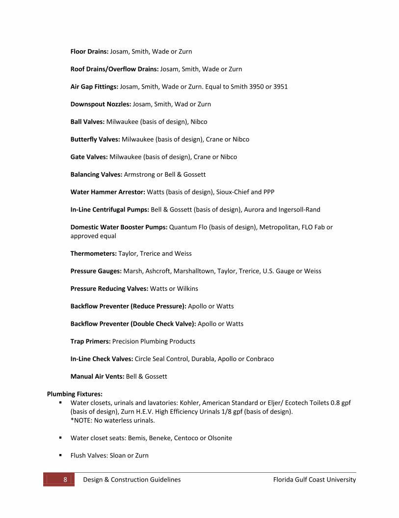
Cleanouts: Josam, Smith, Wade or Zurn
8 Design & Construction Guidelines Florida Gulf Coast University
Floor Drains: Josam, Smith, Wade or Zurn
Roof Drains/Overflow Drains: Josam, Smith, Wade or Zurn
Air Gap Fittings: Josam, Smith, Wade or Zurn. Equal to Smith 3950 or 3951
Downspout Nozzles: Josam, Smith, Wad or Zurn
Ball Valves: Milwaukee (basis of design), Nibco
Butterfly Valves: Milwaukee (basis of design), Crane or Nibco
Gate Valves: Milwaukee (basis of design), Crane or Nibco
Balancing Valves: Armstrong or Bell & Gossett
Water Hammer Arrestor: Watts (basis of design), Sioux-Chief and PPP
In-Line Centrifugal Pumps: Bell & Gossett (basis of design), Aurora and Ingersoll-Rand
Domestic Water Booster Pumps: Quantum Flo (basis of design), Metropolitan, FLO Fab or approved equal
Thermometers: Taylor, Trerice and Weiss
Pressure Gauges: Marsh, Ashcroft, Marshalltown, Taylor, Trerice, U.S. Gauge or Weiss
Pressure Reducing Valves: Watts or Wilkins
Backflow Preventer (Reduce Pressure): Apollo or Watts
Backflow Preventer (Double Check Valve): Apollo or Watts
Trap Primers: Precision Plumbing Products
In-Line Check Valves: Circle Seal Control, Durabla, Apollo or Conbraco
Manual Air Vents: Bell & Gossett
Plumbing Fixtures: Water closets, urinals and lavatories: Kohler, American Standard or Eljer/ Ecotech Toilets 0.8 gpf
(basis of design), Zurn H.E.V. High Efficiency Urinals 1/8 gpf (basis of design). *NOTE: No waterless urinals.
Water closet seats: Bemis, Beneke, Centoco or Olsonite
Flush Valves: Sloan or Zurn
9 Design & Construction Guidelines Florida Gulf Coast University
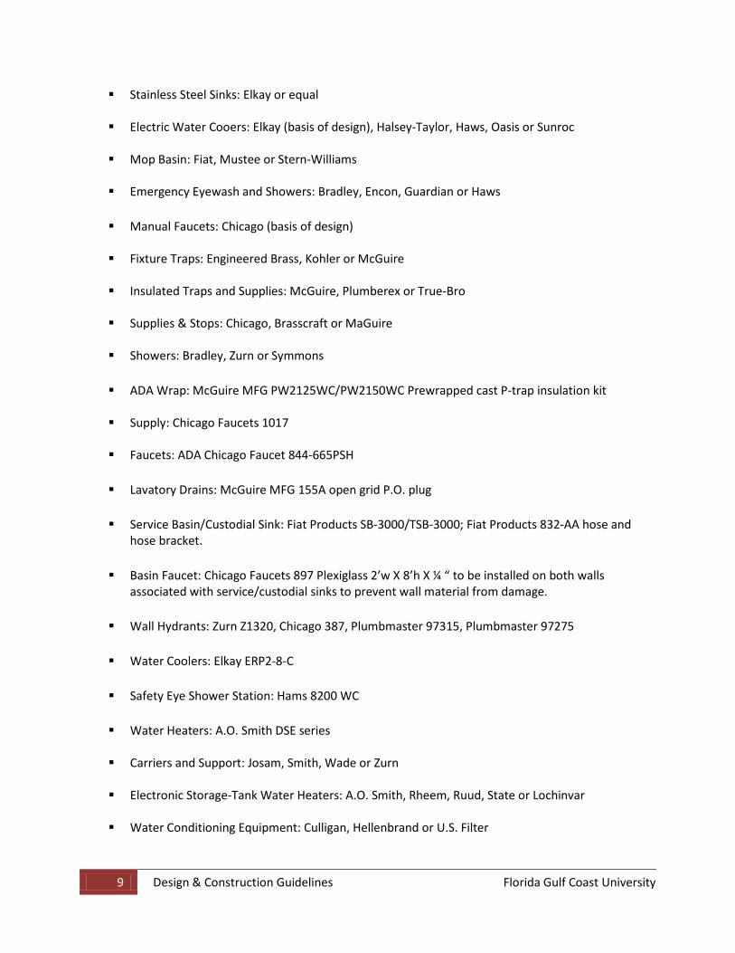
Stainless Steel Sinks: Elkay or equal
Electric Water Cooers: Elkay (basis of design), Halsey-Taylor, Haws, Oasis or Sunroc
Mop Basin: Fiat, Mustee or Stern-Williams
Emergency Eyewash and Showers: Bradley, Encon, Guardian or Haws
Manual Faucets: Chicago (basis of design)
Fixture Traps: Engineered Brass, Kohler or McGuire
Insulated Traps and Supplies: McGuire, Plumberex or True-Bro
Supplies & Stops: Chicago, Brasscraft or MaGuire
Showers: Bradley, Zurn or Symmons
ADA Wrap: McGuire MFG PW2125WC/PW2150WC Prewrapped cast P-trap insulation kit
Supply: Chicago Faucets 1017
Faucets: ADA Chicago Faucet 844-665PSH
Lavatory Drains: McGuire MFG 155A open grid P.O. plug
Service Basin/Custodial Sink: Fiat Products SB-3000/TSB-3000; Fiat Products 832-AA hose and hose bracket.
Basin Faucet: Chicago Faucets 897 Plexiglass 2’w X 8’h X ¼ “ to be installed on both walls associated with service/custodial sinks to prevent wall material from damage.
Wall Hydrants: Zurn Z1320, Chicago 387, Plumbmaster 97315, Plumbmaster 97275
Water Coolers: Elkay ERP2-8-C
Safety Eye Shower Station: Hams 8200 WC
Water Heaters: A.O. Smith DSE series
Carriers and Support: Josam, Smith, Wade or Zurn Electronic Storage-Tank Water Heaters: A.O. Smith, Rheem, Ruud, State or Lochinvar
Water Conditioning Equipment: Culligan, Hellenbrand or U.S. Filter
10 Design & Construction Guidelines Florida Gulf Coast University
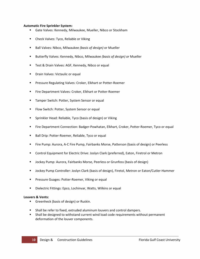
Automatic Fire Sprinkler System: Gate Valves: Kennedy, Milwaukee, Mueller, Nibco or Stockham
Check Valves: Tyco, Reliable or Viking
Ball Valves: Nibco, Milwaukee (basis of design) or Mueller
Butterfly Valves: Kennedy, Nibco, Milwaukee (basis of design) or Mueller
Test & Drain Valves: AGF, Kennedy, Nibco or equal
Drain Valves: Victaulic or equal
Pressure Regulating Valves: Croker, Elkhart or Potter‐Roemer
Fire Department Valves: Croker, Elkhart or Potter‐Roemer
Tamper Switch: Potter, System Sensor or equal
Flow Switch: Potter, System Sensor or equal
Sprinkler Head: Reliable, Tyco (basis of design) or Viking
Fire Department Connection: Badger‐Powhatan, Elkhart, Croker, Potter‐Roemer, Tyco or equal
Ball Drip: Potter‐Roemer, Reliable, Tyco or equal
Fire Pump: Aurora, A‐C Fire Pump, Fairbanks Morse, Patterson (basis of design) or Peerless
Control Equipment for Electric Drive: Joslyn Clark (preferred), Eaton, Firetrol or Metron
Jockey Pump: Aurora, Fairbanks Morse, Peerless or Grunfoss (basis of design)
Jockey Pump Controller: Joslyn Clark (basis of design), Firetol, Metron or Eaton/Cutler‐Hammer
Pressure Guages: Potter‐Roemer, Viking or equal
Dielectric Fittings: Epco, Lochinvar, Watts, Wilkins or equal
Louvers & Vents: Greenheck (basis of design) or Ruskin.
Shall be refer to fixed, extruded aluminum louvers and control dampers. Shall be designed to withstand current wind load code requirements without permanent
deformation of the louver components.
11 Design & Construction Guidelines Florida Gulf Coast University
Provide louvers that allow for thermal movements resulting from the following maximum range or change in ambient and surface temperatures by preventing buckling, opening of joints, over-stressing of components and failure of connections.
All louvers to be factory assembled, with equal blade spacing for a uniform appearance.
Provide bird screening: Aluminum, ½” square mesh, 0.063 inch wire: and insect screening:
Aluminum, 18x16 mesh, 0.102 inch wire.
Finishes to comply with NAAMM’s “Metal Finishes Manual for Architectural and Metal Products”.
Packaged Air Handling Units: York (Basis of Design) or Trane Heating & Cooling Terminal Devices: Fan Coil Units: Trane or York
Electric Reheat Coils: Indeeco, Singer, Brasch, Warren or Titus
Fans: Centrifugal Fans: Greenheck (basis of design), Cook, York or Trane
Plenum Fans: Greenheck (basis of design), Cook, York, Trane or Twin City
Fiberglass Reinforced Plastic Centrifugal Fans: MK Plastic (basis of design), Chicago Blower or
Horrington
Tubular Centrifugal Fans: Greenheck (basis of design) or Cook
Power Roof Exhausters: Greenheck (basis of design) or Cook
Mixed Flow Induced Dilutiom Fans: Vektor or Greenheck (basis of design) Filters: Disposable Panel Filters: Farr 30/30 or Flanders PrePleat 40
Disposable Rigid Cartridge Type Air Filters: Farr or Flanders Precisionaire
Bag Filters: size, capacity and efficiency as scheduled
HEPA Filters: size, capacity and static pressure drop as scheduled
Bag In-Bag Out Filtration and Housing Assembly: Flanders/CSC, American Air, Camfil, Farr,
Barnesby-Cheney or Tri-Dim Filter Pressure Drop Gauges: Dwyer Series 200 Magnehlic Air Terminal Devices: VAV Terminal Devices: Titus (Basis of Design), Price, York, Kruger or Enviro-Tech
12 Design & Construction Guidelines Florida Gulf Coast University
Diffusers, Registers and Grilles: Titus (Basis of Design) E.H. Price, Carnes or Krueger Ductwork: All duct products shall conform to NFPA 90A, and shall possess flame spread rating of not over
25, and a smoke developed rating no higher than 50.
Ductwork shall comply with Local, State and Federal requirements, and meet current ASTM standards for the type of duct being utilized.
Ductwork Specialties: Manual Balancing Dampers: Ruskin or Air Balance
Backdraft Dampers: Ruskin, Air Balance or Greenheck
Fire Dampers: Air Balance, Greenheck, Nailor, Cesco, Pottorff or Ruskin
Combination Fire and Smoke Dampers: Ruskin, Air Balance or Greenheck
Smoke Dampers: Air Balance, Johnson Controls, Ruskin or Greenheck
Remote Operated Volume Control Dampers: Determined by Controls Contractor
Control System Integration: Currently, Johnson Controls, Inc. is the FGCU site standard contractor.
The control system shall be 100% Direct Digital Control unless otherwise specified.
Damper and valve actuators shall be electronic type unless otherwise specified.
The contractor shall provide BAS architecture consisting of communication network, operator
workstations, modular designed DDCP’s with points addressable and modifiable from operator work stations or from master DDCP using laptop computer. BAS shall be fully expandable with addition of hardware and/or software. Such expansion shall not require the removal of existing DDCP’s, sensors, actuators or communication networks.
The system shall support operator workstations as specified and shall be capable of supporting additional workstations, limited only by systems maximum node capacity.
System Intelligence shall be that operator workstation(s) can be used for programming controls, performing analysis of filed data, generating maintenance and operations reports and providing permanent storage for programs and data.
Safety devices shall function in both VFD and bypass modes. Control Wiring: Control Wiring shall be in accordance with the National Electric Code and Local Electrical codes.
Refer to Division 16 for additional information.
13 Design & Construction Guidelines Florida Gulf Coast University
Transient Voltage Surge Suppression Devices shall be designed for 120 V. power conditioning devices for electronic equipment.
Uninterruptable Power Supply: MGE UPS Systems, Invensys Powerware, Liebert PowerSure or approved equal.
Local Control Panels: Unless otherwise specified, the local control panels shall be the manufacturers standard panels.
Construction for exterior panels shall comply with NEMA 4.
Functioning shall be consistent with existing University systems.
Direct Digital Controllers and Networks: Digital equipment furnished shall comply to applicable FCC regulations.
Functioning shall be consistent with existing University systems.
Direct Digital Control Panel: Shall be microprocessor based, field programmable controllers, capable of performing control
and energy management functions, and shall be UL Listed as Signaling Systems.
Functioning shall be consistent with existing University systems. Direct Digital Control Software: Control strategies shall be Owner Definable from operator terminals or workstations.
Software functions and algorithms shall be sufficient to enable implementation of control
sequences as specified and shall be able to maintain continuous control as intended.
Control functions shall be both mathematical and logical operators.
Allow operators to assign identifiers of their choice to each connected point.
Provide access control (user defined passwords) for system operation.
Each DDCP shall contain self-diagnostics that continuously monitor proper operation of panel.
14 Design & Construction Guidelines Florida Gulf Coast University
ELECTRICAL
1. All utility work shall be coordinated with and approved by the Utilities Section through the Project Manager. Each drawing that shows a connection to existing utilities shall have a note stating the Contractor shall request permission for all outages a minimum of 14 days in advance, unless an emergency arises. Explicit details shall be shown for all connections to existing utilities. The Utilities Section must approve both the location and the method of the proposed connection.
General
2. The Contractor, through the Project Manager, shall pay for all electric energy consumed during
construction. The Contractor shall obtain the Utilities Procurement Procedures from the Project Manager. Requirements for establishing service are as detailed. Drawings shall clearly call for the Contractor to take such action.
3. All electrical materials and equipment shall be UL or ETL listed. CSA is not considered equivalent.
4. All materials and types of construction shall meet or exceed the requirements of UL, ANSI, NEMA, IEEE, and the NEC as well as conform to manufacturer’s written recommendations.
5. Record Drawings that accurately reflect the actual installed conditions must be furnished on both hard line drawings and CAD discs at the end of the project. Inaccurate, incomplete Record Drawings may be cause to reject a pay request or deter classifying the project complete.
6. An authorized representative(s) of the Owner shall witness an operational demonstration of completed systems. Representative(s) shall be completely instructed in the operation and maintenance of installed equipment. Representative(s) shall sign and date a statement that confirms they’ve received proper, comprehensive training.
7.
• ALL COPPER WIRING – NO ALUMINUM WIRING Electrical Specifications
• Switchgear/Panelboards: Square D/Siemens/General Electric
Dead front with bolt-in main and branch protective devices
Mount on 4” concrete pad with 4” extending on all sides
• Transformers: Square D NLP series All service transformers are to be suitable for High Harmonic Environments, rated minimum
of 200% of normal harmonic content with a minimum ‘K’ factor of 13.
‘K’-factor transformers shall be Shielded isolation type and have primary surge suppression, secondary filters and electrostatic shields.
Mount on 3” concrete pad with 3” extending on all sides.
• Disconnects/Motor Starters: Square D/Siemens/General Electric

15 Design & Construction Guidelines Florida Gulf Coast University
• TVSS: LEA Dyna-Tech/Liebert/Leviton One to be installed on main switch board and one on secondary side of transformers.
• Identification: Nameplates shall be laminated phenlic plastic, black front and back with white core, with
lettering etched through outer covering.
White engraved letters on black background. Attach with plated self tapping screws or brass bolts. The following shall be equipped with name plates: all motors, motor starters, push button
stations, control panels, time switches, disconnect switches, panel boards, circuit breakers, contractors, transformers.
All junction boxes to be identified with panel and circuit numbers. All distribution panel boards shall have typed directories identifying circuit locations such as:
duplex outlet room 120 SW wall. NO HAND WRITTEN OR XEROXED DIRECTORIES WILL BE ACCEPTED. All devices on standby generators are to be ‘RED’ in color including device plates.
BASIC MATERIALS AND METHODS
1. Schedule 40 PVC is permitted for exterior lighting, minimum 1”, and buried to a depth called for by the NEC. When a junction box is installed near a pole location, a ¾” conduit may be used from the junction box to the pole. If no junction box is installed, the 1” conduit shall extend to the pole foundation.
Conduits
2. PVC bends shall be made with a hot box. Flames or hairdryers are unacceptable.
3. PVC shall be converted to metallic where exposed to physical damage. Buried metallic conduit must
have, minimum, two coats of bitumastic or have factory applied PVC coating.
4. All empty conduits shall have a 200-pound test pull cord. Conduit shall be manufactured in the United States.
WIRES AND CABLES 1. Conductors shall be copper. Insulation shall be Type THHN/THWN. Minimum power conductor size
is #12AWG. Control conductor sizes and color-coding shall be as governed by approved wiring diagrams or schematics. Power conductors shall be sized for maximum 5% voltage drop from source to point of utilization. Wire #12 AWG and smaller shall be solid, larger-stranded.
16 Design & Construction Guidelines Florida Gulf Coast University
1. All wire and cable shall be installed in conduit or where applicable, tray-rated cable in cable trays. In lieu of wire in conduit, MC cable may be used in areas allowed by the NEC, but only with the joint approval of the Engineer of Record, the FGCU BCA, and FGCU Plan Reviewers.
MC Cable
1. Conduit systems shall be identified by the color code listed below. If a color code is already in use in a building, then that code will be utilized for that building. If no code is in use, then this one shall be used. If an existing building system is being modified, these requirements apply only to the new raceway system.
Conduit Systems Identification
SYSTEM Fire Alarm Red
COLOR
Emergency Power (Life Safety Branch) Yellow Critical Branch Orange Equipment Branch Green Essential Distribution Purple (Genset Output to Line Side of ATS) Normal Power Blue Security Brown
2. The last six inches of conduits, their junction boxes, and their covers shall be painted the appropriate color.
3. For power conduits, the circuits and panels involved shall be identified on the junction box covers
using a black permanent marker. PANELBOARDS 1. Panelboards shall be identified using permanently attached machine engraved phenolic nameplates.
Standard color shall be white letters on black background. Emergency panels shall have white letters on a red background. Panelboard bus shall be copper. Lighting and receptacle panelboard neutral bus shall be rated 100%. Panelboards shall be sized for minimum 20% spare above calculated diversified demand loads.
2. Circuit breakers shall be bolt-on construction. Devices shall be rated for the calculated available bolted fault short circuit currents. Copies of the fault current calculations shall be furnished to the Project Manager for review with plans prior to construction.
3. Main Distribution panels shall have metal oxide varistor (MOV) type surge protection device (SPD). The MOV device shall have a short circuit current rating of 200 kA or greater. The MOV shall be rated for service voltage of the facility.
1. Switches and receptacles shall be specification grade and rated 20 amperes. Standard color shall be ivory with stainless steel plates. Devices assigned to the emergency system shall be distinctive in color: red is considered standard unless another color code has already been established in an existing facility.
Switches and Receptacles
17 Design & Construction Guidelines Florida Gulf Coast University
2. Vending areas shall have outlets mounted no greater than 48” on center. Hallways shall have outlets mounted 50 feet on center, maximum.
3. Outlets shall be provided on the exterior of facilities located according to the geometry of their footprint and good design, so that their spacing does not exceed 100 feet on center.
4. Device mounting heights shall conform to the latest applicable edition of ADA standards. Floor outlets shall be flush with finished floor or floor covering, as applicable.
5. When required for classrooms, receptacles for overhead LCD projector shall be mounted flush with ceiling.
MOTORS AND STARTERS 1. Motors shall be high efficiency and have an operating power factor of 90% or greater. Provide
reduced voltage starters or variable speed drives for all motors 15 horsepower, or larger. Variable speed drives shall be connected to the campus-wide energy management system. For detailed requirements for these connections, contact the Physical Plant Department. For a list of acceptable manufacturers of VFD’s see the Mechanical section of these guidelines.
POWER GENERATION 1. Where required for life safety per NFPA-101 and/or for continuity of function in certain facilities,
provide a standby rated emergency power engine generator set. The addition of battery-powered lighting, instead of providing a generator set, to meet NFPA-101 exit/egress requirements is highly discouraged.
2. Engine generator set shall be diesel fueled unless so small that diesel prime mover is not commercially available. Natural gas and LP fueled sets are unacceptable. Fuel tank shall be sized for minimum 36 hours of operation at full load. Larger tanks may be required to serve facilities where continuity of function is mandatory. The operation and fueling requirements for those types of facilities shall be handled on a project-by-project basis as design criteria through the Project Manager. Fuel tanks shall be above ground and approved by EPA. If fuel tank is of such dimension that the top of the mounting skid is 24” or greater AFG, then a substantial maintenance platform shall be constructed around all sides. Platform shall be in full accordance with all applicable OSHA safety standards for handrails, etc.
3. The set shall be started electrically using its own properly rated and sized batteries. Air start is unacceptable.
4. Engine generator set shall connect to building power distribution system through coil and contactor operated automatic transfer switches. “Walking Beam” switches are unacceptable. Transfer switch shall have an integral, field adjustable automatic exerciser clock.
5. In addition to other requirements, the generator set shall have the capacity to serve, as a minimum, one elevator, all building data gathering panels used for HVAC control and management systems, steam condensate return pumps, and sump pumps. Generators shall be sized for minimum 20% spare above calculated diversified demand loads.
18 Design & Construction Guidelines Florida Gulf Coast University
6. Generator shall conform to ISO-9001; have Class H insulation, and permanent magnet excitation for production of 300% of rated full load current for ten seconds.
7. Generator set on-site acceptance testing shall be performed in accordance with NFPA-110 at 80%
and 100% power factors. Generator Shop personnel shall be notified of the test schedule so that they may attend.
8. Contractor shall furnish a full tank of fuel at the completion of all acceptance testing. 9. Equipment supplier shall supply two operation and maintenance manuals. Deliver to the Director of
Physical Plant. 10. There are numerous locations on campus where terrain or geometry of adjacent structures may
require that the generator set be installed in a sound attenuated enclosure with a rated sound attenuating silencer. This requirement will need to be discussed during initial design meetings and the actual level of attenuation determined early in the design process.
11. Sets shall be installed on building exteriors except possibly for locations such as energy/utility plants.
The location of the generator set shall be coordinated with the relative location of the fresh air intake for the building to minimize the intrusion of the generator’s exhaust fumes into the building air conditioning system. Unit shall be located and physically protected in such a manner as to reduce the vulnerability to damage by severe storms or hurricanes.
12. Generator set shall be cooled with self-contained coolant and radiator system. Remote coolers are
unacceptable. All systems shall have a five-year warranty, unless the project considerations dictate differently and is approved by the Physical Plant Department. Engine generator sets shall be Caterpillar or Cummins/Onan all other manufacturers are unacceptable.
SERVICE AND DISTRIBUTION
1. Electric service to buildings and facilities on campus will normally be served from Florida Power and Light voltage distribution system. If a building is not served from an existing sectionalizing device, a new SF6 gas insulated vacuum fault interrupter device shall be installed. Interrupters shall have 600-ampere separable quick change bushings. G & W is the only acceptable manufacturer. A 6 lb bottle of SF6 gas shall be furnished with all new sectionalizing switch installations.
Electrical Service
2. Service to buildings shall be supplied from pad-mounted transformers as described below. The
transformers, service entrance conductors or bus, and main electrical panel or equipment shall be of adequate size for the demand expected in the facility and to allow for future growth of 25% based on calculated diversified demand.
3. Transformers shall be located as close as possible to the main electric service room. Future servicing or replacement of transformers shall be a consideration when selecting a location. The transformer shall be protected from vehicular and pedestrian traffic.
4. The location of the building electric service apparatus shall be incorporated in the landscaping as much as possible.
19 Design & Construction Guidelines Florida Gulf Coast University
METERING 1. A watt-hour meter with a demand register shall be provided for each building. This shall be
coordinated through the University Project Manager with the Utilities Section.
2. For buildings being served by a pad mounted transformer, the meter shall be mounted on a meter pedestal. Metering current transformers shall be installed in the secondary compartment of the transformer. A 1 ¼ “conduit shall be installed from the pad to the nearest building system control junction box.
GROUNDING 1. All grounding for building services, standby generators, and transformers shall achieve a maximum
10- ohms or less as required by specific project criteria, using the three-point test method. If necessary, multiple rods shall be driven to achieve the desired resistance to ground. All grounds shall be connected with a properly sized copper conductor. All ground busses shall be connected to ground rods by either (1) an approved exothermic welding process as manufactured by Erico or (2) a compression system as manufactured by Burndy known as ‘Hyground’. Each rod shall be tested in the presence of the University's representative. A written record of the test results shall be prepared and signed by the contractor and University’s representative. This record shall be submitted to the Architect/Engineer and supplied to the University with the “Record Drawings” and reports upon the completion of the project.
1. It is the responsibility of the Architect/Engineer to insure the proper electric circuit coordination. Circuit Coordination
1. The Engineer shall provide breaker settings for all new or remodeled building electrical systems. Circuit coordination parameters shall be furnished, including time-current characteristic curve plots, breaker/relay settings, and verification that all settings have been made.
Facility Electrical Systems
1. The Engineer shall provide arc-flash data for all electrical systems installation as required by the NEC, NFPA-70E, and all local codes.
Arc Flash Data
2. Pertinent signs pertaining to arc-flash information shall be prominently displayed on all equipment
involved, i.e. Panelboards, switchgear, motor controllers.
1. Pad mounted transformers are the responsibility of Florida Power and Light. Pad-Mounted Transformers
DUCT BANK SYSTEM 1. The duct bank system will be the responsibility of Florida Power and Light.
MANHOLES 1. The manholes will be the responsibility of Florida Power and Light. LIGHTNING PROTECTION SYSTEMS 1. All buildings/structures shall have appropriate lightning protection systems designed and installed in
accordance with NFPA-780. Installer shall be LPI certified. Installed system shall bear a Master Label.
20 Design & Construction Guidelines Florida Gulf Coast University
2. Expansions of existing facilities shall upgrade the existing lightning protection system as required to obtain or maintain a Master Label for the envelope.
LIGHTING SYSTEMS
1. All lighting designs shall comply with the current edition of the Illuminating Engineers Society (IES) standard.
General
1. The standard lighting system shall utilize fluorescent T5 lamps with electronic ballasts having a total harmonic distortion (THD) of less than 10%. Interior systems that are not dimmed shall employ 28W lamps where ambient temperatures and other conditions are suitable for their application. Dimmable systems shall use 32W lamps. Wherever possible, four-foot lamps are to be used. The lamp color to be: T41 – cool white. Other colors for lamps are not acceptable.
Interior Lighting
2. Light fixtures in stairways shall be above the landings and not above the steps. Automatic lighting
controls shall comply with Chapter 13, ENERGY EFFICIENCY, Florida Building Code. 3. Emergency lighting shall be provided at all exits and in all stairways, hallways, mechanical rooms and
elevators according to NFPA-101. Emergency lighting shall be powered from the building emergency generator system. Battery powered emergency lighting shall not be used unless there is no emergency generator associated with the project.
4. Where emergency lights are required in classrooms, a bypass switch shall be installed to permit the
light to be switched off during special presentations. During actual power failures, the bypass shall be rendered inoperative.
5. No lights shall be installed that require scaffolding for relamping. 6. Exit lights shall be of the Light Emitting Diode (LED) type.
1. Classroom lighting shall comply with DOE requirements. Lighting in classrooms and lecture halls with seating capacity greater than 25 people shall be equipped fluorescent dimming systems.
Classroom Lighting
2. For detail requirements for dimming and occupancy sensor systems refer to Appendix E, Design
Criteria and Requirements for Classrooms at Florida State University. OUTDOOR LIGHTING 1. Outdoor lighting on the FGCU campus shall be attractive and in keeping with the standards set forth
in this section. The lighting plan shall be energy efficient while maintaining appropriate light level(s) as prescribed in the latest edition of the NFPA codes and IES handbook for high activity facilities.
2. When outdoor lighting is associated with a building project, security lighting and parking lot lighting shall be included in the building design.
3. No lights are to be installed that require scaffolding for relamping. Pole mounted parking lot lights shall be bucket truck accessible.
21 Design & Construction Guidelines Florida Gulf Coast University
4. Walkway and exterior security lighting shall be controlled by a photoelectric cell and contactor, with a manual override for maintenance.
5. Outdoor lighting shall be period style fixtures, pole mounted where possible. Poles and fixtures shall be: See Appendix R. 1) Fixtures: All fixtures shall use high-pressure sodium lamps. All ballasts shall be multi-voltage
tapped (120,208,240, and 277-volt taps). Globes/diffusers shall be glass. Plastic is unacceptable. Precision injection-molded, UV stabilized, acrylic lens is acceptable for parking deck fixtures. • Walkway type fixtures: Fixture trim shall be green.
Acceptable manufacturers are: King Luminare 11’ poles
• Parking Lot Fixtures: Fixtures shall be green. Acceptable manufacturers are:
King Luminare 30’ poles
• Roadway type fixtures: Fixture trim shall be green. King Luminare 35’ poles
PARKING DECK LIGHTING 1. The consultant shall evaluate the feasibility of installing lighting control systems that monitor and
control the “interior” and “exterior” zones lighting according to available ambient levels. The control systems shall be field adjustable to owner’s specifications.
2. A control system recommendation shall be presented to the Project Manager no later than the 50% plans submittal.
FIRE ALARM SYSTEMS Basic Requirements for New InstallationAll new buildings, and buildings undergoing major renovations, shall be equipped with a complete fire alarm system which meets Florida Building Code, Chapter 11 Accessibility Code for Building Construction (Section 11-4.28) and current code requirements. Provide all hardware necessary to tie-in with the existing campus monitoring system. Matching the existing addressable digital fire system in use in a facility is preferred.
LicensingAll work on fire alarm systems shall be performed by an individual, or firm, licensed as an
"Alarm System Contractor I" as required by Florida Statute 489.505(a), other parts of said Statute, and complies with all other licensing requirements of relevant codes and laws. Further, this individual or firm shall be either the prime constructor on such work or a subcontractor to the prime constructor.
1. Central Fire Control Panel: Provide programmable central fire control panel with programmable field devices. Fire control panel shall meet NFPA 72 detector sensitivity readout/printout requirements. A history of a minimum of 200 events shall be readable on the fire alarm control panel display (200 events for alarm and 200 events for trouble).
Panels
2. Annunciator Panel: Annunciator panel shall be located where the fire department will enter
building. Annunciation panel shall duplicate all functions of the fire control panel.
22 Design & Construction Guidelines Florida Gulf Coast University
3. Renovations: When the existing fire alarm control panel does not support the type of renovation being performed in a building, a second (or third) fire alarm control panel shall be installed. The fire alarm control panels installed for the renovation shall be of sufficient capacity to handle the entire building when the existing fire system(s) is (are) changed.
4. Simplex: Verify design with the Director of Physical Plant. Pull StationsPull stations shall be single action type. Glass rods for pull stations are discouraged. In housing units pull stations shall be equipped with a protective tamper shield. The protective tamper shield shall be a clear Lexan cover that emits a loud piercing noise when disturbed. The cover shall be battery powered and shall silence itself by lowering and realigning the shield. Stopper II as manufactured by Safety Technology International, Inc. (STI), are acceptable covers. Protective shields shall only be used to protect pull stations from the elements, or in locations where vandalism is likely (such as next to exterior exits). They are not required throughout the interior of a building.
Alarm units shall be combination audible alarm and strobe light. The audible alarm shall be a horn, not a bell, as a bell could be confused with a class bell. Provide separate power for horns and lights, so that lights can be checked without sounding horn.
Alarm Units
The Air Handling Unit shutdown relay shall be supervised. Air Handling Unit Shutdown Relay
All junction boxes on the fire alarm system shall be painted fire-truck red and all conduit shall be spot painted red.
Junction Boxes and Conduit
Trouble contacts shall be Normally Open; Alarm contacts shall be Normally Open. Provide a Keltron- Digital Alarm Communicator Transmitter (DACT) for digital, secondary reporting to the University Police.
Campus Monitoring System Interface Relays
Duct mounted detectors shall be mounted in a readily accessible location. If duct-mounted smoke detectors are not immediately visible from inside the mechanical room, then provide a remote, labeled L.E.D indicator for each detector, mounted in a convenient, visible location. Non-radioactive smoke detectors and duct detectors are preferred (i.e. photoelectric). Provide stand-alone, duct mounted smoke detectors where no fire alarm system is present. The operation shall be to shut down the unit, and provide notification.
Duct-Mounted Smoke Detectors
1. Provide a spare parts kit that shall include one of every type of field device (one pull station, one horn, one strobe).
Maintenance Items
2. Any special tools, equipment, programming devices and cables needed to maintain or repair the
system shall be provided.
23 Design & Construction Guidelines Florida Gulf Coast University
3. All keys or tools provided with any devices from the manufacturer shall be given to the Physical Plant Department.
1. All equipment shall be installed to provide adequate access for service and repair. Execution
2. On retrofit projects that involve adding to existing wiring, the Constructor shall exactly match the
colors of the new wiring with the existing. All new wiring shall be installed in conduit unless approved by the Physical Plant Department.
3. The Constructor shall certify and tag the system after all modifications are made and prior to
1. The installer and the EHS Fire Safety Systems Electronics Shop shall test the fire alarm system before any renovation or modification is made. Any part of the system not working properly shall be noted or repaired before any construction begins.
Substantial Completion
2. Fire alarm conductors shall be color coded as follows:
• Horns: Red +, Black - • Strobes: (if separate) White + Purple - • Alarms: Blue + Yellow - • A/C Ventilation: Shut Down Brown + Orange - • Magnetic Doors: Pink + Grey - • Misc. Circuits: Violet + Tan -
3. Data line wiring shall be twisted shielded 18 gauge FPLP wire in a red jacket. All data wire shall meet
current code requirements and manufacturer's specifications. Speaker wiring shall meet current code requirements and manufacturer's specifications, and have a different color jacket than the data wiring (minimum 18 gauge twisted shielded).
4. On renovations always remove existing wiring and install new, properly color coded wiring. 5. On renovations, in addition to the renovation prints and/or drawings, the existing prints are to be
up-dated to include any changes. 6. Horns and lights shall be provided in machine rooms and loft/attic areas that have mechanical
equipment or work areas. 7. All connections shall be made on terminal strips. No more than two conductors under one
connection. Wires on these terminals shall be labeled. Programming of the fire alarm shall be as specified by the University. Consult with the Physical Plant Department concerning the requirements. Programming includes, but is not limited to: function keys, FAAP, software zones, etc.
8. All fire and smoke alarm sensors shall be re-settable. Beam detectors are discouraged and must be
approved by the Physical Plant Department. 9. Provide protection from damage caused by lightning and electrical surges. OPERATION
24 Design & Construction Guidelines Florida Gulf Coast University
Actuation of any fire alarm initiating device shall cause all air handlers in the building area affected to shut down. Air handling units shall shut down only in the area where the fire is detected or the area actually alarmed (floor above and below). Other air handling equipment shall remain on line. This shall not supersede any code requirement.
Air Handling Units
ElevatorsA reset procedure for resetting the elevators after an alarm shall be submitted.
Trouble signal shall sound piezoelectric alarm on the fire alarm control panel. Trouble Signal
Stand Alone Duct DetectorsProvide an enunciator panel to provide notification of trouble alarm and reset feature. Panel to be 120 Volts.
1. Keys to the system and associated equipment shall be given to the Physical Plant Department when the system is accepted.
Maintenance Items
2. All spare parts, special tools, equipment, keys, etc. required for maintenance or operation shall be
turned over to the Physical Plant Department when the system is accepted. 3. A copy of the field prints, drawings, etc. shall be given to the Physical Plant Department when the
system is accepted.