Embed Size (px)
Citation preview
Materials Research, Vol. 9, No. 2, 121-130, 2006 © 2006
*e-mail: [email protected]
Mechanical Performance of Carbon-epoxy Laminates Part II: Quasi-static and Fatigue Tensile Properties
José Ricardo Tarpani*, Marcelo Tadeu Milan, Dirceu Spinelli, Waldek Wladimir Bose
Materials, Aeronautics and Automotive Engineering Department, Engineering School of São Carlos, The University of São Paulo, Brazil
Received: November 5, 2003; Revised: December 29, 2005
In Part II of this work, quasi-static tensile properties of four aeronautical grade carbon-epoxy composite laminates, in both the as-received and pre-fatigued states, have been determined and compared. Quasi-static mechanical properties assessed were tensile strength and stiffness, tenacity (toughness) at the maximum load and for a 50% load drop-off. In general, as-molded unidirectional cross-ply carbon fiber (tape) reinforcements impregnated with either standard or rubber-toughened epoxy resin exhibited the maximum performance. The materials also displayed a significant tenacification (toughening) after exposed to cyclic loading, resulting from the increased stress (the so-called wear-in phenomenon) and/or strain at the maximum load capacity of the specimens. With no exceptions, two-dimensional woven textile (fabric) pre-forms fractured catastrophically under identical cyclic loading conditions imposed to the fiber tape architecture, thus preventing their residual properties from being determined.
Keywords: carbon-epoxy laminates, composite materials, mechanical properties
1. Introduction
Part I of this study focused on the quasi-static and dynamic bending properties of several carbon-epoxy composite laminates extensively used in the Brazilian aeronautical industry5. The general conclusion was that bidirectional woven carbon fiber fabric array embedded in rubber-toughened epoxy resin is the best option to op-erate under those conditions. The obtained results justified, to some extent, the use of more expensive raw materials (and associated higher processing costs) compared to concurrent standard epoxy resin grades impregnating simple cross-ply unidirectional tapes.
Part II describes quasi-static tensile properties of the same ma-terials, with special emphasis in the residual strength of pre-fatigued testpieces. It is well known1-4 that individual trans-laminar (matrix cracking) and inter-laminar (interior delaminations) damage are the earliest and most prevalent fracture modes in composites subject to fatigue. In the damage accumulation chronology, fiber break con-stitute the most advanced and critical stage of cyclic degradation of mechanical properties of this class of structural materials. Thermo-setting polymer matrix composite manufacturers claim that stronger and more ductile resin matrix, e.g., rubber-toughened epoxy resin grades, improves the laminates performance under cyclic loading through the reduction of matrix damage.
This study intends to assess this statement by comparing more expensive rubber-toughened epoxy resin to a cheaper standard grade, both impregnating cross-ply tapes and bidirectional fabric pre-forms of high-performance reinforcing carbon fibers.
2. Materials and Test Specimens
The materials and specimens tested were previously described in Part I. In Part II, all the 65.0 x 27.5 x 1.5 mm3 tablet-shape tes-pieces were centrally notched in order to induce a preferential tensile fracture path5.
The nomenclature TP and FB has been maintained to refer, respectively, to the cross-ply unidirectional tape and bidirectional
(8 Harness Satin) woven carbon fiber fabric pre-forms. Epoxy resin grades have been identified through their cure temperature, namely 120 °C and 180 °C for standard and rubber-toughened polymers, respectively.
3. Experimental Procedures
Monotonic tensile tests of as-molded and pre-fatigued materi-als were carried out at room temperature and loading rates of 1 and 5 mm/min, respectively, in an EMICTM testing system. The between-grips distance was fixed in 15 mm, with load and load-train displace-ment being monitored digitally throughout the test until the complete rupture of the specimens. Tensile properties evaluated were stiffness, S
t, ultimate tensile strength, TS, tenacity at the maximum load, TML
t,
and for a 50% load drop-off from maximum load, TDMLt50
. The te-nacity (toughness) parameters, TML
t and TDML
t50, were calculated
by numerical integration of the area under the stress-displacement diagram, from the beginning of the test until the point of interest.
Fatigue tensile tests were conducted in a servo-hydraulic MTSTM testing machine, at room temperature, load ratio R = 0.1 and two sinusoidal loading frequencies, 5 and 50 Hz, respectively. Sequential blocks of cyclic loading were applied in a step-up manner, which eventually conducted the catastrophic failure of the specimens.
Typically, three specimens were tested to each loading condition.
4. Results and Discussion
4.1. Monotonic tensile tests
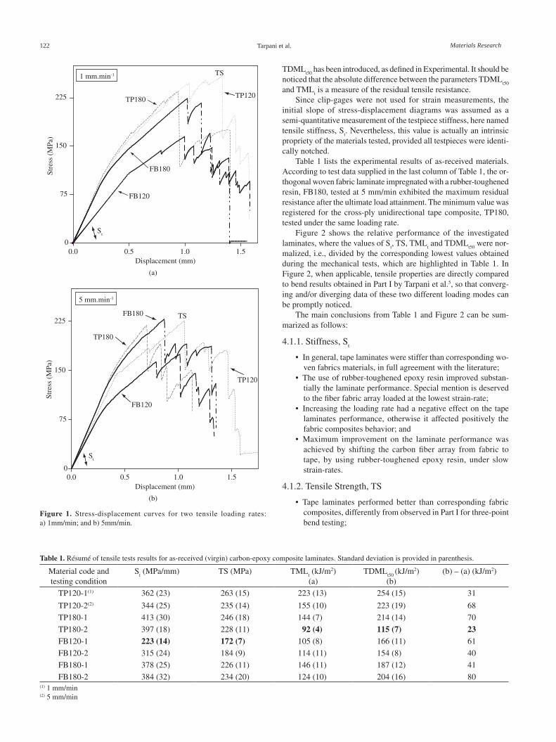
Figure 1 displays tensile stress-displacement curves of virgin laminates tested at two constant loading rates. The materials exhibited considerable residual resistance after the maximum load attainment, differently from three-point bend tests conducted in Part I. In order to quantify this residual resistance, a tenacity parameter nominated
122 Tarpani et al. Materials Research
TDMLt50
has been introduced, as defined in Experimental. It should be noticed that the absolute difference between the parameters TDML
t50
and TMLt is a measure of the residual tensile resistance.
Since clip-gages were not used for strain measurements, the initial slope of stress-displacement diagrams was assumed as a semi-quantitative measurement of the testpiece stiffness, here named tensile stiffness, S
t. Nevertheless, this value is actually an intrinsic
propriety of the materials tested, provided all testpieces were identi-cally notched.
Table 1 lists the experimental results of as-received materials. According to test data supplied in the last column of Table 1, the or-thogonal woven fabric laminate impregnated with a rubber-toughened resin, FB180, tested at 5 mm/min exhibited the maximum residual resistance after the ultimate load attainment. The minimum value was registered for the cross-ply unidirectional tape composite, TP180, tested under the same loading rate.
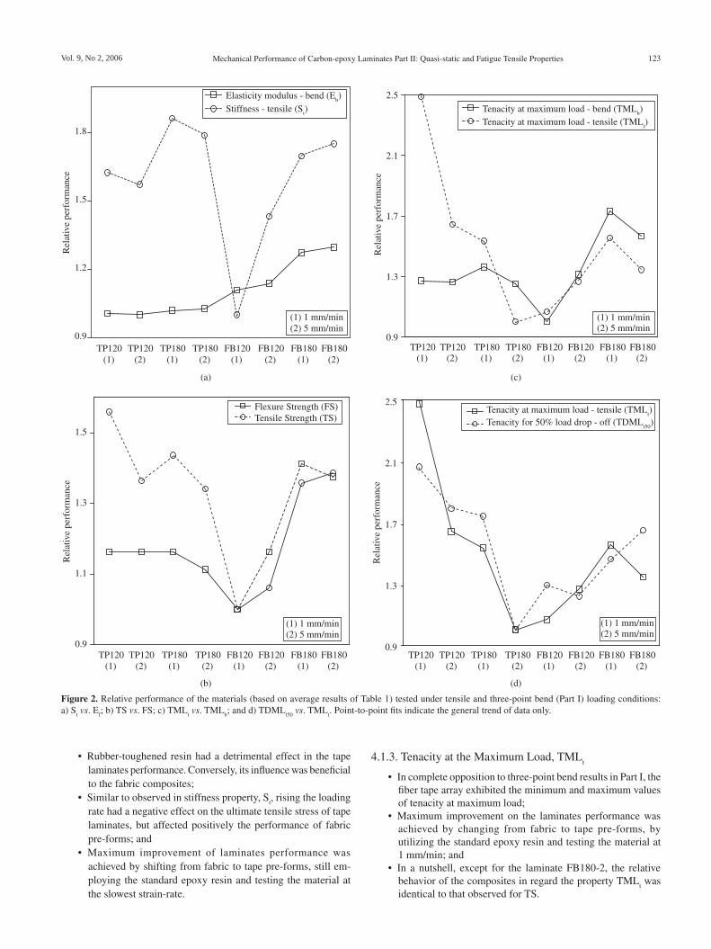
Figure 2 shows the relative performance of the investigated laminates, where the values of S
t, TS, TML
t and TDML
t50 were nor-
malized, i.e., divided by the corresponding lowest values obtained during the mechanical tests, which are highlighted in Table 1. In Figure 2, when applicable, tensile properties are directly compared to bend results obtained in Part I by Tarpani et al.5, so that converg-ing and/or diverging data of these two different loading modes can be promptly noticed.
The main conclusions from Table 1 and Figure 2 can be sum-marized as follows:
4.1.1. Stiffness, St
• In general, tape laminates were stiffer than corresponding wo-ven fabrics materials, in full agreement with the literature;
• The use of rubber-toughened epoxy resin improved substan-tially the laminate performance. Special mention is deserved to the fiber fabric array loaded at the lowest strain-rate;
• Increasing the loading rate had a negative effect on the tape laminates performance, otherwise it affected positively the fabric composites behavior; and
• Maximum improvement on the laminate performance was achieved by shifting the carbon fiber array from fabric to tape, by using rubber-toughened epoxy resin, under slow strain-rates.
4.1.2. Tensile Strength, TS
• Tape laminates performed better than corresponding fabric composites, differently from observed in Part I for three-point bend testing;
0
75
150
225
0.0 0.5 1.0 1.5Displacement (mm)
Stre
ss (
MPa
)
1 mm.min-1
St
TS
TP120
FB180
FB120
TP180
(a)
0
75
150
225
0.0 0.5 1.0 1.5Displacement (mm)
Stre
ss (
MPa
)
St
TS
FB120
FB180
TP120
TP180
5 mm.min-1
(b)
Figure 1. Stress-displacement curves for two tensile loading rates: a) 1mm/min; and b) 5mm/min.
Table 1. Résumé of tensile tests results for as-received (virgin) carbon-epoxy composite laminates. Standard deviation is provided in parenthesis.
Material code and testing condition
St (MPa/mm) TS (MPa) TML
t (kJ/m2)(a)
TDMLt50
(kJ/m2)(b)
(b) – (a) (kJ/m2)
TP120-1(1) 362 (23) 263 (15) 223 (13) 254 (15) 31
TP120-2(2) 344 (25) 235 (14) 155 (10) 223 (19) 68
TP180-1 413 (30) 246 (18) 144 (7) 214 (14) 70
TP180-2 397 (18) 228 (11) 92 (4) 115 (7) 23FB120-1 223 (14) 172 (7) 105 (8) 166 (11) 61
FB120-2 315 (24) 184 (9) 114 (11) 154 (8) 40
FB180-1 378 (25) 226 (11) 146 (11) 187 (12) 41
FB180-2 384 (32) 234 (20) 124 (10) 204 (16) 80(1) 1 mm/min(2) 5 mm/min
Vol. 9, No 2, 2006 Mechanical Performance of Carbon-epoxy Laminates Part II: Quasi-static and Fatigue Tensile Properties 123
• Rubber-toughened resin had a detrimental effect in the tape laminates performance. Conversely, its influence was beneficial to the fabric composites;
• Similar to observed in stiffness property, St, rising the loading
rate had a negative effect on the ultimate tensile stress of tape laminates, but affected positively the performance of fabric pre-forms; and
• Maximum improvement of laminates performance was achieved by shifting from fabric to tape pre-forms, still em-ploying the standard epoxy resin and testing the material at the slowest strain-rate.
4.1.3. Tenacity at the Maximum Load, TMLt
• In complete opposition to three-point bend results in Part I, the fiber tape array exhibited the minimum and maximum values of tenacity at maximum load;
• Maximum improvement on the laminates performance was achieved by changing from fabric to tape pre-forms, by utilizing the standard epoxy resin and testing the material at 1 mm/min; and
• In a nutshell, except for the laminate FB180-2, the relative behavior of the composites in regard the property TML
t was
identical to that observed for TS.
Figure 2. Relative performance of the materials (based on average results of Table 1) tested under tensile and three-point bend (Part I) loading conditions: a) S
t vs. E
f; b) TS vs. FS; c) TML
t vs. TML
b; and d) TDML
t50 vs. TML
t. Point-to-point fits indicate the general trend of data only.
0.9
1.2
1.5
1.8
Rel
ativ
e pe
rfor
man
ce
Elasticity modulus - bend (Eb)
Stiffness - tensile (St)
TP120(1)
TP120(2)
TP180(1)
TP180(2)
FB120(1)
FB120(2)
FB180(1)
FB180(2)
(1) 1 mm/min(2) 5 mm/min
(a)
0.9
1.3
1.7
2.1
2.5
Rel
ativ
e pe
rfor
man
ce
Tenacity at maximum load - bend (TMLb)
Tenacity at maximum load - tensile (TMLt)
TP120(1)
TP120(2)
TP180(1)
TP180(2)
FB120(1)
FB120(2)
FB180(1)
FB180(2)
(1) 1 mm/min(2) 5 mm/min
(c)
0.9
1.1
1.3
1.5
Rel
ativ
e pe
rfor
man
ce
Flexure Strength (FS)Tensile Strength (TS)
TP120(1)
TP120(2)
TP180(1)
TP180(2)
FB120(1)
FB120(2)
FB180(1)
FB180(2)
(1) 1 mm/min(2) 5 mm/min
0.9
1.3
1.7
2.1
2.5
Rel
ativ
e pe
rfor
man
ce
Tenacity at maximum load - tensile (TMLt)
Tenacity for 50% load drop - off (TDMLt50
)
TP120(1)
TP120(2)
TP180(1)
TP180(2)
FB120(1)
FB120(2)
FB180(1)
FB180(2)
(1) 1 mm/min(2) 5 mm/min
(b) (d)
124 Tarpani et al. Materials Research
4.1.4. Tenacity for a 50% load drop-off, TDMLt50
• Similar to the property TMLt, TDML
t50 reached both its maxi-
mum and minimum values for the tape configuration;• Increasing the loading rate impaired the performance of fabric
pre-forms impregnated with standard epoxy resin grade. In regard to the rubber-toughened resin, raising the loading rate had otherwise a beneficial effect; and
• As for the properties TS e TMLt, maximum improvement on
the laminates performance was achieved by shifting the fiber configuration from fabric to tape, by using the standard epoxy resin and testing the composite material at 1 mm/min.
The results described above indicate that, in a general sense, carbon fiber tape pre-form impregnated with standard epoxy grade may be the best choice among all possible fiber/resin combinations. However, if stiffness is the main concern, the use of rubber-toughened resin might be mandatory.
4.2. Fatigue tests
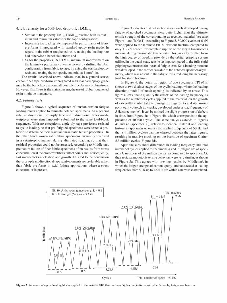
Figure 3 shows a typical sequence of tension-tension fatigue loading block applied to laminate notched specimens. As a general rule, unidirectional cross-ply tape and bidirectional fabric-made testpieces were simultaneously submitted to the same load-block sequences. With no exceptions, angle-ply tape pre-forms resisted to cyclic loading, so that pre-fatigued specimens were tested a pos-teriori to determine their residual quasi-static tensile properties. On the other hand, woven satin fabric specimens invariably fractured in a catastrophic manner during alternated loading, so that their residual properties could not be assessed. According to Middleton6, premature failure of fiber fabric specimens often results from stress concentration at the crossover fiber contact points and, consequently, fast microcracks nucleation and growth. This led to the conclusion that cross-ply unidirectional tape reinforcements are preferable rather than fabric pre-forms in axial fatigue applications where a stress concentrator is present.
Figure 3 indicates that net section stress levels developed during fatigue of notched specimens were quite higher than the ultimate tensile strength of the corresponding as-received material (see also Figure 1 and Table 1). According to Figure 3, 50,000 cycles of 6 kN were applied to the laminate FB180 without fracture, compared to only 3.3 kN needed for complete rupture of the virgin (as-molded) material during quasi-static tensile tests. This basically resulted from the high degree of freedom provide by the orbital gripping system utilized in the quasi-static tensile testing, compared to the fully rigid gripping system used for the axial fatigue tests. So, a bending moment was developed in the former case due to the notched-specimen asym-metry, which was absent in the fatigue tests, reducing the necessary load for static fracture.
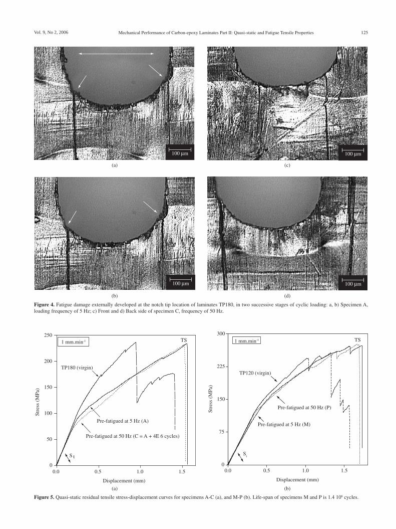
In Figure 4, the notch tip region of two specimens TP180 is shown at two distinct stages of the cyclic loading, where the loading direction (mode I of notch opening) is indicated by an arrow. This figure allows one to quantify the effects of the loading frequency, as well as the number of cycles applied to the material, on the growth of externally visible fatigue damage. In Figures 4a and 4b, arrows point out two notch tip cracks, developed under a load frequency of 5 Hz (specimen A). It can be noticed the slight progression of defects in time, from Figure 4a to Figure 4b, which corresponds to the ap-plication of 500,000 cycles. The same analysis extends to Figures 4c and 4d (specimen C), related to identical material and loading history as specimen A, unless the applied frequency of 50 Hz and that a 4 million cycles-span has elapsed between the latter figures, resulting in massive cracking on the backside of specimen C after 5.3 million cycles (Figure 4d).
Apart the substantial differences in loading frequency and total number of cycles applied to specimens A and C (fatigue life of speci-men C in excess of 3.8 million cycles, as compared to specimen A), their residual monotonic tensile behaviors were very similar, as shown in Figure 5a. This agrees with previous results by Middleton6, in which the fatigue strength of carbon-epoxy laminates tested at loading frequencies from 5 Hz up to 120 Hz are within a narrow scatter band.
FB180; 5 Hz; room temperature; R = 0.1Tensile strength (Virgin) = 3.3 kN
Cycles
Tens
ile lo
ad
Total number of cycles 1.63 E6
2.5 kN (167 MPa)
4E5 4E5 3.2E5 4.6E5 5E4
3 kN (200 MPa)
4 kN (267 MPa)
5 kN (333 MPa)
Pmax
= 6 kNfinal fracture
7 kN
25% life
20% life27% life
03% life
Pmin
25% life
Figure 3. Sequence of cyclic loading blocks applied to the material FB180 (specimen D), leading to its catastrophic failure by fatigue mechanisms.
Vol. 9, No 2, 2006 Mechanical Performance of Carbon-epoxy Laminates Part II: Quasi-static and Fatigue Tensile Properties 125
100 m
100 m
100 m
100 m
(a) (c)
(d)(b)
Figure 4. Fatigue damage externally developed at the notch tip location of laminates TP180, in two successive stages of cyclic loading: a, b) Specimen A, loading frequency of 5 Hz; c) Front and d) Back side of specimen C, frequency of 50 Hz.
0
50
100
150
200
250
0.0 0.5 1.0 1.5
Displacement (mm)
Stre
ss (
MPa
)
1 mm.min-1
S t
TS
Pre-fatigued at 5 Hz (A)
Pre-fatigued at 50 Hz (C = A + 4E 6 cycles)
TP180 (virgin)
(a)
0
75
150
225
300
0.0 0.5 1.0 1.5
Displacement (mm)
Stre
ss (
MPa
)
1 mm.min-1
St
TS
Pre-fatigued at 5 Hz (M)
Pre-fatigued at 50 Hz (P)
TP120 (virgin)
(b)
Figure 5. Quasi-static residual tensile stress-displacement curves for specimens A-C (a), and M-P (b). Life-span of specimens M and P is 1.4 106 cycles.
126 Tarpani et al. Materials Research
Optical inspection of fatigued specimens, as supplied in Figure 4, coupled with experimental data provided in Figure 5a allows one to postulated that the significant fatigue damage mechanisms leading to changes in the residual strength of the laminates, namely matrix cracking and delamination, are mostly developed during the first and a half million cycles, which corresponds exactly to the life-span of specimen A.
It can be noticed in Figure 5a that prior fatigue loading suppressed the post-maximum load resistance exhibited by the virgin material (see also Figure 1). Still in Figure 5a, a small but consistent effect of fatigue in reducing the materials’ stiffness, S
t, can be observed.
However, in regard to the ultimate tensile strength, TS, of pre-fatigued laminates, virtually no alteration occurred, relatively to the original material (TP180). On the other hand, a significant increase in the strain at the maximum load of specimens A and C is verified, when compared to that virgin material (see also Figure 1). The same trend is observed in Figure 5b, for specimens M and P (both TP120 lami-nates), apart from the remarkable accompanying increase as well in the ultimate tensile strength of the laminates due to fatigue loading. It should be noted that test specimens M and P underwent exactly the same loading conditions (i.e., load spectrum and testing frequency) as testpieces A and C (both TP180 laminates), respectively.
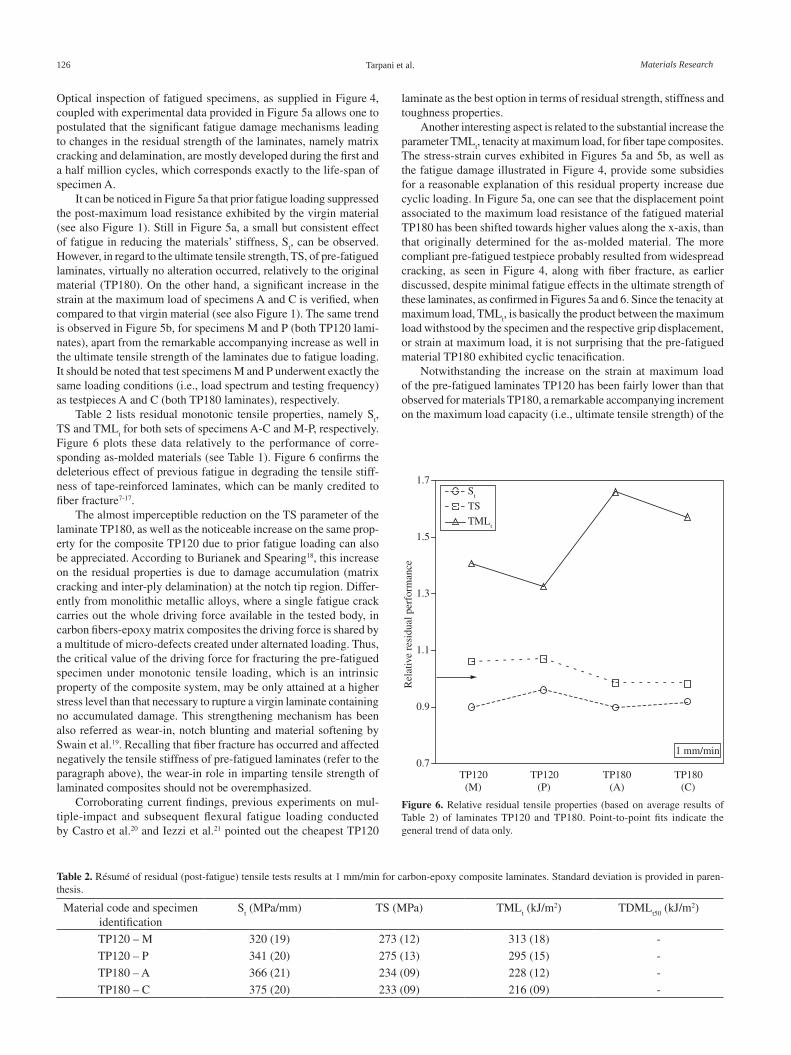
Table 2 lists residual monotonic tensile properties, namely St,
TS and TMLt for both sets of specimens A-C and M-P, respectively.
Figure 6 plots these data relatively to the performance of corre-sponding as-molded materials (see Table 1). Figure 6 confirms the deleterious effect of previous fatigue in degrading the tensile stiff-ness of tape-reinforced laminates, which can be manly credited to fiber fracture7-17.
The almost imperceptible reduction on the TS parameter of the laminate TP180, as well as the noticeable increase on the same prop-erty for the composite TP120 due to prior fatigue loading can also be appreciated. According to Burianek and Spearing18, this increase on the residual properties is due to damage accumulation (matrix cracking and inter-ply delamination) at the notch tip region. Differ-ently from monolithic metallic alloys, where a single fatigue crack carries out the whole driving force available in the tested body, in carbon fibers-epoxy matrix composites the driving force is shared by a multitude of micro-defects created under alternated loading. Thus, the critical value of the driving force for fracturing the pre-fatigued specimen under monotonic tensile loading, which is an intrinsic property of the composite system, may be only attained at a higher stress level than that necessary to rupture a virgin laminate containing no accumulated damage. This strengthening mechanism has been also referred as wear-in, notch blunting and material softening by Swain et al.19. Recalling that fiber fracture has occurred and affected negatively the tensile stiffness of pre-fatigued laminates (refer to the paragraph above), the wear-in role in imparting tensile strength of laminated composites should not be overemphasized.
Corroborating current findings, previous experiments on mul-tiple-impact and subsequent flexural fatigue loading conducted by Castro et al.20 and Iezzi et al.21 pointed out the cheapest TP120
Table 2. Résumé of residual (post-fatigue) tensile tests results at 1 mm/min for carbon-epoxy composite laminates. Standard deviation is provided in paren-thesis.
Material code and specimen identification
St (MPa/mm) TS (MPa) TML
t (kJ/m2) TDML
t50 (kJ/m2)
TP120 – M 320 (19) 273 (12) 313 (18) -
TP120 – P 341 (20) 275 (13) 295 (15) -
TP180 – A 366 (21) 234 (09) 228 (12) -
TP180 – C 375 (20) 233 (09) 216 (09) -
0.7
0.9
1.1
1.3
1.5
1.7
Rel
ativ
e re
sidu
al p
erfo
rman
ce
St
TS
TMLt
TP120(M)
TP120(P)
TP180(A)
TP180(C)
1 mm/min
Figure 6. Relative residual tensile properties (based on average results of Table 2) of laminates TP120 and TP180. Point-to-point fits indicate the general trend of data only.
laminate as the best option in terms of residual strength, stiffness and toughness properties.
Another interesting aspect is related to the substantial increase the parameter TML
t, tenacity at maximum load, for fiber tape composites.
The stress-strain curves exhibited in Figures 5a and 5b, as well as the fatigue damage illustrated in Figure 4, provide some subsidies for a reasonable explanation of this residual property increase due cyclic loading. In Figure 5a, one can see that the displacement point associated to the maximum load resistance of the fatigued material TP180 has been shifted towards higher values along the x-axis, than that originally determined for the as-molded material. The more compliant pre-fatigued testpiece probably resulted from widespread cracking, as seen in Figure 4, along with fiber fracture, as earlier discussed, despite minimal fatigue effects in the ultimate strength of these laminates, as confirmed in Figures 5a and 6. Since the tenacity at maximum load, TML
t, is basically the product between the maximum
load withstood by the specimen and the respective grip displacement, or strain at maximum load, it is not surprising that the pre-fatigued material TP180 exhibited cyclic tenacification.
Notwithstanding the increase on the strain at maximum load of the pre-fatigued laminates TP120 has been fairly lower than that observed for materials TP180, a remarkable accompanying increment on the maximum load capacity (i.e., ultimate tensile strength) of the
Vol. 9, No 2, 2006 Mechanical Performance of Carbon-epoxy Laminates Part II: Quasi-static and Fatigue Tensile Properties 127
100 m
(a)
200 m
(b)
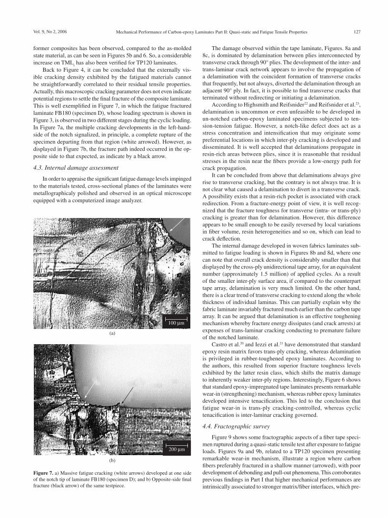
Figure 7. a) Massive fatigue cracking (white arrows) developed at one side of the notch tip of laminate FB180 (specimen D); and b) Opposite-side final fracture (black arrow) of the same testpiece.
former composites has been observed, compared to the as-molded state material, as can be seen in Figures 5b and 6. So, a considerable increase on TML
t has also been verified for TP120 laminates.
Back to Figure 4, it can be concluded that the externally vis-ible cracking density exhibited by the fatigued materials cannot be straightforwardly correlated to their residual tensile properties. Actually, this macroscopic cracking parameter does not even indicate potential regions to settle the final fracture of the composite laminate. This is well exemplified in Figure 7, in which the fatigue fractured laminate FB180 (specimen D), whose loading spectrum is shown in Figure 3, is observed in two different stages during the cyclic loading. In Figure 7a, the multiple cracking developments in the left-hand-side of the notch signalized, in principle, a complete rupture of the specimen departing from that region (white arrowed). However, as displayed in Figure 7b, the fracture path indeed occurred in the op-posite side to that expected, as indicate by a black arrow.
4.3. Internal damage assessment
In order to appraise the significant fatigue damage levels impinged to the materials tested, cross-sectional planes of the laminates were metallographicaly polished and observed in an optical microscope equipped with a computerized image analyzer.
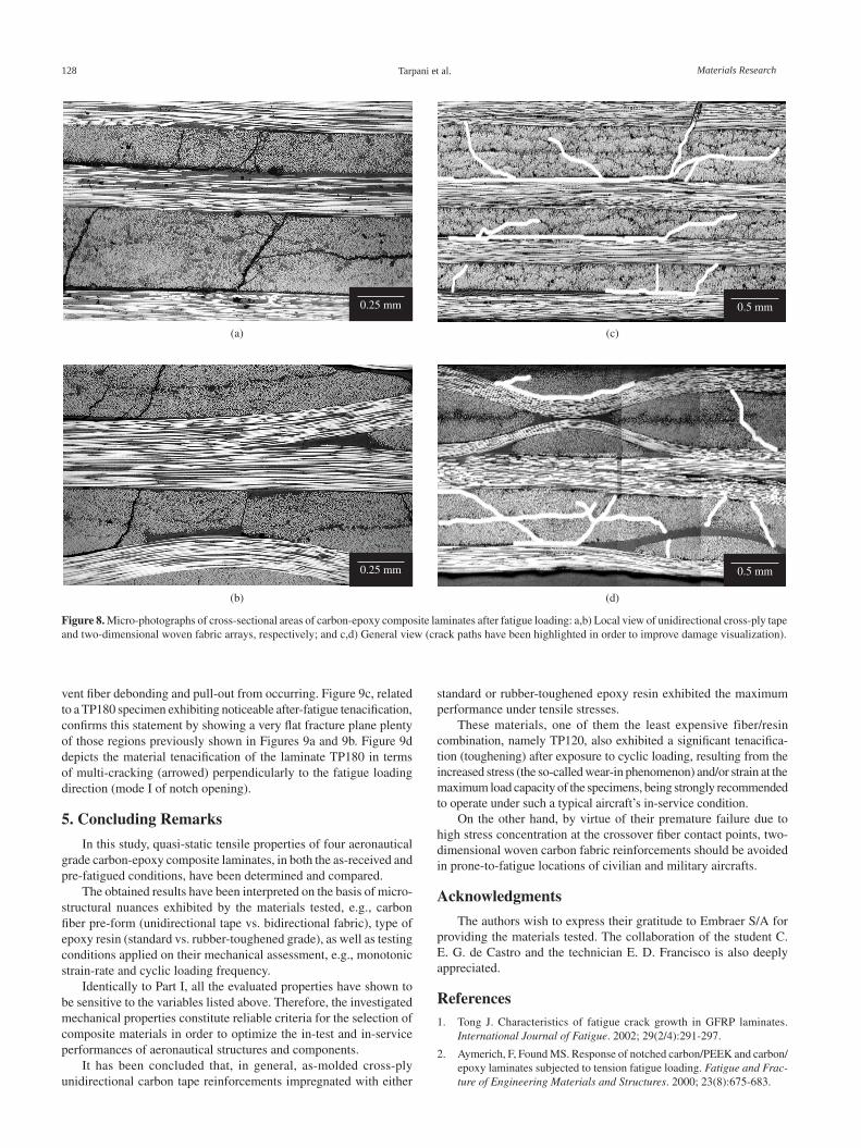
The damage observed within the tape laminate, Figures. 8a and 8c, is dominated by delamination between plies interconnected by transverse crack through 90° plies. The development of the inter- and trans-laminar crack network appears to involve the propagation of a delamination with the coincident formation of transverse cracks that frequently, but not always, diverted the delamination through an adjacent 90° ply. In fact, it is possible to find transverse cracks that terminated without redirecting or initiating a delamination.
According to Highsmith and Reifsnider22 and Reifsnider et al.23, delamination is uncommon or even unfeasible to be developed in un-notched carbon-epoxy laminated specimens subjected to ten-sion-tension fatigue. However, a notch-like defect does act as a stress concentration and intensification that may originate some preferential locations in which inter-ply cracking is developed and disseminated. It is well accepted that delaminations propagate in resin-rich areas between plies, since it is reasonable that residual stresses in the resin near the fibers provide a low-energy path for crack propagation.
It can be concluded from above that delaminations always give rise to transverse cracking, but the contrary is not always true. It is not clear what caused a delamination to divert in a transverse crack. A possibility exists that a resin-rich pocket is associated with crack redirection. From a fracture-energy point of view, it is well recog-nized that the fracture toughness for transverse (intra- or trans-ply) cracking is greater than for delamination. However, this difference appears to be small enough to be easily reversed by local variations in fiber volume, resin heterogeneities and so on, which can lead to crack deflection.
The internal damage developed in woven fabrics laminates sub-mitted to fatigue loading is shown in Figures 8b and 8d, where one can note that overall crack density is considerably smaller than that displayed by the cross-ply unidirectional tape array, for an equivalent number (approximately 1.5 million) of applied cycles. As a result of the smaller inter-ply surface area, if compared to the counterpart tape array, delamination is very much limited. On the other hand, there is a clear trend of transverse cracking to extend along the whole thickness of individual laminas. This can partially explain why the fabric laminate invariably fractured much earlier than the carbon tape array. It can be argued that delamination is an effective toughening mechanism whereby fracture energy dissipates (and crack arrests) at expenses of trans-laminar cracking conducting to premature failure of the notched laminate.
Castro et al.20 and Iezzi et al.21 have demonstrated that standard epoxy resin matrix favors trans-ply cracking, whereas delamination is privileged in rubber-toughened epoxy laminates. According to the authors, this resulted from superior fracture toughness levels exhibited by the latter resin class, which shifts the matrix damage to inherently weaker inter-ply regions. Interestingly, Figure 6 shows that standard epoxy-impregnated tape laminates presents remarkable wear-in (strengthening) mechanism, whereas rubber epoxy laminates developed intensive tenacification. This led to the conclusion that fatigue wear-in is trans-ply cracking-controlled, whereas cyclic tenacification is inter-laminar cracking governed.
4.4. Fractographic survey
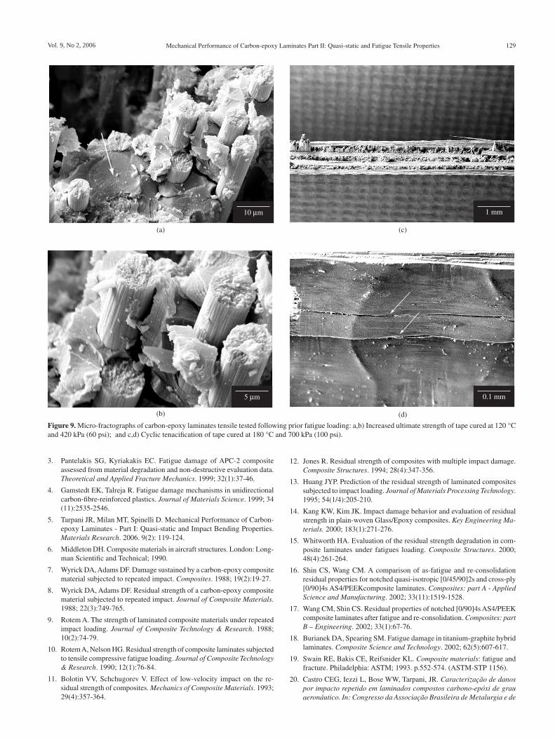
Figure 9 shows some fractographic aspects of a fiber tape speci-men ruptured during a quasi-static tensile test after exposure to fatigue loads. Figures 9a and 9b, related to a TP120 specimen presenting remarkable wear-in mechanism, illustrate a region where carbon fibers preferably fractured in a shallow manner (arrowed), with poor development of debonding and pull-out phenomena. This corroborates previous findings in Part I that higher mechanical performances are intrinsically associated to stronger matrix/fiber interfaces, which pre-
128 Tarpani et al. Materials Research
0.25 mm
0.25 mm
0.5 mm
0.5 mm
(a) (c)
(d)(b)
Figure 8. Micro-photographs of cross-sectional areas of carbon-epoxy composite laminates after fatigue loading: a,b) Local view of unidirectional cross-ply tape and two-dimensional woven fabric arrays, respectively; and c,d) General view (crack paths have been highlighted in order to improve damage visualization).
vent fiber debonding and pull-out from occurring. Figure 9c, related to a TP180 specimen exhibiting noticeable after-fatigue tenacification, confirms this statement by showing a very flat fracture plane plenty of those regions previously shown in Figures 9a and 9b. Figure 9d depicts the material tenacification of the laminate TP180 in terms of multi-cracking (arrowed) perpendicularly to the fatigue loading direction (mode I of notch opening).
5. Concluding Remarks
In this study, quasi-static tensile properties of four aeronautical grade carbon-epoxy composite laminates, in both the as-received and pre-fatigued conditions, have been determined and compared.
The obtained results have been interpreted on the basis of micro-structural nuances exhibited by the materials tested, e.g., carbon fiber pre-form (unidirectional tape vs. bidirectional fabric), type of epoxy resin (standard vs. rubber-toughened grade), as well as testing conditions applied on their mechanical assessment, e.g., monotonic strain-rate and cyclic loading frequency.
Identically to Part I, all the evaluated properties have shown to be sensitive to the variables listed above. Therefore, the investigated mechanical properties constitute reliable criteria for the selection of composite materials in order to optimize the in-test and in-service performances of aeronautical structures and components.
It has been concluded that, in general, as-molded cross-ply unidirectional carbon tape reinforcements impregnated with either
standard or rubber-toughened epoxy resin exhibited the maximum performance under tensile stresses.
These materials, one of them the least expensive fiber/resin combination, namely TP120, also exhibited a significant tenacifica-tion (toughening) after exposure to cyclic loading, resulting from the increased stress (the so-called wear-in phenomenon) and/or strain at the maximum load capacity of the specimens, being strongly recommended to operate under such a typical aircraft’s in-service condition.
On the other hand, by virtue of their premature failure due to high stress concentration at the crossover fiber contact points, two-dimensional woven carbon fabric reinforcements should be avoided in prone-to-fatigue locations of civilian and military aircrafts.
Acknowledgments
The authors wish to express their gratitude to Embraer S/A for providing the materials tested. The collaboration of the student C. E. G. de Castro and the technician E. D. Francisco is also deeply appreciated.
References1. Tong J. Characteristics of fatigue crack growth in GFRP laminates.
International Journal of Fatigue. 2002; 29(2/4):291-297.
2. Aymerich, F, Found MS. Response of notched carbon/PEEK and carbon/epoxy laminates subjected to tension fatigue loading. Fatigue and Frac-ture of Engineering Materials and Structures. 2000; 23(8):675-683.
Vol. 9, No 2, 2006 Mechanical Performance of Carbon-epoxy Laminates Part II: Quasi-static and Fatigue Tensile Properties 129
3. Pantelakis SG, Kyriakakis EC. Fatigue damage of APC-2 composite assessed from material degradation and non-destructive evaluation data. Theoretical and Applied Fracture Mechanics. 1999; 32(1):37-46.
4. Gamstedt EK, Talreja R. Fatigue damage mechanisms in unidirectional carbon-fibre-reinforced plastics. Journal of Materials Science. 1999; 34 (11):2535-2546.
5. Tarpani JR, Milan MT, Spinelli D. Mechanical Performance of Carbon-epoxy Laminates - Part I: Quasi-static and Impact Bending Properties. Materials Research. 2006. 9(2): 119-124.
6. Middleton DH. Composite materials in aircraft structures. London: Long-man Scientific and Technical; 1990.
7. Wyrick DA, Adams DF. Damage sustained by a carbon-epoxy composite material subjected to repeated impact. Composites. 1988; 19(2):19-27.
8. Wyrick DA, Adams DF. Residual strength of a carbon-epoxy composite material subjected to repeated impact. Journal of Composite Materials. 1988; 22(3):749-765.
9. Rotem A. The strength of laminated composite materials under repeated impact loading. Journal of Composite Technology & Research. 1988; 10(2):74-79.
10. Rotem A, Nelson HG. Residual strength of composite laminates subjected to tensile compressive fatigue loading. Journal of Composite Technology & Research. 1990; 12(1):76-84.
11. Bolotin VV, Schchugorev V. Effect of low-velocity impact on the re-sidual strength of composites. Mechanics of Composite Materials. 1993; 29(4):357-364.
12. Jones R. Residual strength of composites with multiple impact damage. Composite Structures. 1994; 28(4):347-356.
13. Huang JYP. Prediction of the residual strength of laminated composites subjected to impact loading. Journal of Materials Processing Technology. 1995; 54(1/4):205-210.
14. Kang KW, Kim JK. Impact damage behavior and evaluation of residual strength in plain-woven Glass/Epoxy composites. Key Engineering Ma-terials. 2000; 183(1):271-276.
15. Whitworth HA. Evaluation of the residual strength degradation in com-posite laminates under fatigues loading. Composite Structures. 2000; 48(4):261-264.
16. Shin CS, Wang CM. A comparison of as-fatigue and re-consolidation residual properties for notched quasi-isotropic [0/45/90]2s and cross-ply [0/90]4s AS4/PEEKcomposite laminates. Composites: part A - Applied Science and Manufacturing. 2002; 33(11):1519-1528.
17. Wang CM, Shin CS. Residual properties of notched [0/90]4s AS4/PEEK composite laminates after fatigue and re-consolidation. Composites: part B – Engineering. 2002; 33(1):67-76.
18. Burianek DA, Spearing SM. Fatigue damage in titanium-graphite hybrid laminates. Composite Science and Technology. 2002; 62(5):607-617.
19. Swain RE, Bakis CE, Reifsnider KL. Composite materials: fatigue and fracture. Philadelphia: ASTM; 1993. p.552-574. (ASTM-STP 1156).
20. Castro CEG, Iezzi L, Bose WW, Tarpani, JR. Caracterização de danos por impacto repetido em laminados compostos carbono-epóxi de grau aeronáutico. In: Congresso da Associação Brasileira de Metalurgia e de
10 m
5 m
1 mm
0.1 mm
(b)
(a) (c)
(d)
Figure 9. Micro-fractographs of carbon-epoxy laminates tensile tested following prior fatigue loading: a,b) Increased ultimate strength of tape cured at 120 °C and 420 kPa (60 psi); and c,d) Cyclic tenacification of tape cured at 180 °C and 700 kPa (100 psi).
130 Tarpani et al. Materials Research
Materiais; 2005; Belo Horizonte, BR. São Paulo: ABM, 2005. p. 1639-1648.
21. Iezzi L, Castro CEG, Bose WW, Tarpani JR. Fadiga pós-impacto repetido em laminados carbono-epóxi de grau aeronáutico. In: Congresso da As-sociação Brasileira de Metalurgia e de Materiais; 2005; Belo Horizonte, BR. São Paulo: ABM, 2005. p. 1630-1638.
22. Highsmith AL, Reifsnider KL. Damage in composite materials. Philadelphia: ASTM; 1982. p. 103-117. (ASTM-STP 775).
23. Reifsnider KL, Schulte K, Duke JC. Fatigue of composite materials. Philadelphia: ASTM; 1983. p. 136-159. (ASTM-STP 813).
Nomenclation
A, C, D testpieces designationE
b Young’s modulus for bend loading, GPa
EMIC trade-mark of testing machineFB fiber fabric arrayFS flexural strength, MPa
M testpiece designationMTS trade-mark of testing machineP testpiece designationP
(max, min) (maximum, minimum) tensile load, kN
R load ratio, dimensionlessSEM scanning electron microscopyS
t tensile stiffness, MPa/mm
TDMLt50
tenacity for a 50% load drop-off, kJ/m2
TMLb tenacity at maximum bending load, kJ/m2
TMLt tenacity at maximum tensile load, kJ/m2
TP fiber tape arrayTS tensile strength, MPa
Subscripts
b relative to bend loadingmax, min relative to maximum, minimum valuest relative to tensile loading


![REVIEW ON MANUFACTURING OF FIBRE METAL LAMINATES …€¦ · laminates (CARALL). In 1989, Glass Laminate Aluminium Reinforced Epoxy (GLARE) was developed and patented [24]. It was](https://img.dokumen.tips/doc/110x75/5ebed44c3bea0860f72f196b/review-on-manufacturing-of-fibre-metal-laminates-laminates-carall-in-1989-glass.jpg)