Embed Size (px)
Citation preview

D e p a r t m e n t o f M e c h a n i c a l a n d N u c l e a r E n g i n e e r i n g , U n i v e r s i t y P a r k , P A
The Development and Analysis of Crack Growth in Ship Structures Using XFEM Technique Group Members:
Sharmin Shabnam
Spring 2016
ME 563: Nonlinear
Finite Element Analysis
A Semester Report on:

The Development and Analysis of Crack Growth in Ship Structures Using XFEM Technique
2
Table of Contents
Table of Contents .................................................................................................................. 2 Executive Summary ............................................................................................................... 3 Acknowledgements ............................................................................................................... 4 Section 1: Background and Project Plan ................................................................................. 5 Section 2: Development and Description of the CAD Geometry .............................................. 6 Section 3: Development of Finite Element Meshes ................................................................. 8 Section 4: Development and Description of the Model Assembly and Boundary Conditions . 10 Section 5: Development and Description of Model Interactions ........................................... 13 Section 6: Analysis of Finite Element Model ......................................................................... 15 Section 7: Summary of Major Findings ................................................................................. 16 Section 8: Works Cited ......................................................................................................... 20
The Development and Analysis of Crack Growth in Ship Structures Using XFEM Technique
3
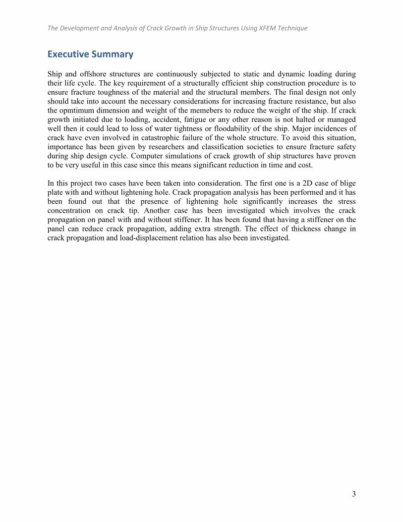
Executive Summary Ship and offshore structures are continuously subjected to static and dynamic loading during their life cycle. The key requirement of a structurally efficient ship construction procedure is to ensure fracture toughness of the material and the structural members. The final design not only should take into account the necessary considerations for increasing fracture resistance, but also the opmtimum dimension and weight of the memebers to reduce the weight of the ship. If crack growth initiated due to loading, accident, fatigue or any other reason is not halted or managed well then it could lead to loss of water tightness or floodability of the ship. Major incidences of crack have even involved in catastrophic failure of the whole structure. To avoid this situation, importance has been given by researchers and classification societies to ensure fracture safety during ship design cycle. Computer simulations of crack growth of ship structures have proven to be very useful in this case since this means significant reduction in time and cost. In this project two cases have been taken into consideration. The first one is a 2D case of blige plate with and without lightening hole. Crack propagation analysis has been performed and it has been found out that the presence of lightening hole significantly increases the stress concentration on crack tip. Another case has been investigated which involves the crack propagation on panel with and without stiffener. It has been found that having a stiffener on the panel can reduce crack propagation, adding extra strength. The effect of thickness change in crack propagation and load-displacement relation has also been investigated.
The Development and Analysis of Crack Growth in Ship Structures Using XFEM Technique
4
Acknowledgements I would like to express my sincere gratitude the the Course Instructor Dr. Reuben Kraft for his guidance and assistance through the entire course and the project completion. He has provided all the necessary information and simulation techniques without which the project would not be possible. I would also like to take this opportunity to thank the Department of Mechanical and Nuclear Engineering of The Pennsylvania State University to provide me the opportunity to be a part of them for the last two semesters.
The Development and Analysis of Crack Growth in Ship Structures Using XFEM Technique
5
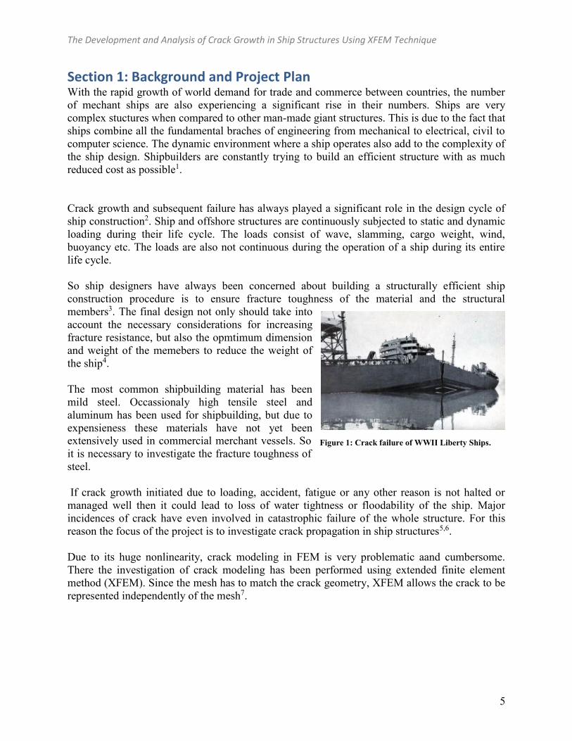
Section 1: Background and Project Plan With the rapid growth of world demand for trade and commerce between countries, the number of mechant ships are also experiencing a significant rise in their numbers. Ships are very complex stuctures when compared to other man-made giant structures. This is due to the fact that ships combine all the fundamental braches of engineering from mechanical to electrical, civil to computer science. The dynamic environment where a ship operates also add to the complexity of the ship design. Shipbuilders are constantly trying to build an efficient structure with as much reduced cost as possible1. Crack growth and subsequent failure has always played a significant role in the design cycle of ship construction2. Ship and offshore structures are continuously subjected to static and dynamic loading during their life cycle. The loads consist of wave, slamming, cargo weight, wind, buoyancy etc. The loads are also not continuous during the operation of a ship during its entire life cycle. So ship designers have always been concerned about building a structurally efficient ship construction procedure is to ensure fracture toughness of the material and the structural members3. The final design not only should take into account the necessary considerations for increasing fracture resistance, but also the opmtimum dimension and weight of the memebers to reduce the weight of the ship4. The most common shipbuilding material has been mild steel. Occassionaly high tensile steel and aluminum has been used for shipbuilding, but due to expensieness these materials have not yet been extensively used in commercial merchant vessels. So it is necessary to investigate the fracture toughness of steel. If crack growth initiated due to loading, accident, fatigue or any other reason is not halted or managed well then it could lead to loss of water tightness or floodability of the ship. Major incidences of crack have even involved in catastrophic failure of the whole structure. For this reason the focus of the project is to investigate crack propagation in ship structures5,6. Due to its huge nonlinearity, crack modeling in FEM is very problematic aand cumbersome. There the investigation of crack modeling has been performed using extended finite element method (XFEM). Since the mesh has to match the crack geometry, XFEM allows the crack to be represented independently of the mesh7.
Figure 1: Crack failure of WWII Liberty Ships.

The Development and Analysis of Crack Growth in Ship Structures Using XFEM Technique
6
Section 2: Development and Description of the CAD Geometry The CAD geometry has been developed in Abaqus8 Model creation section. Four distinct sets of model had been tried in this project. The first two models are 2D planar and the rest two models are 3D.
1. Bilge Bracket
2. Bilge Bracket with Lightening Hole
1050mm
600mm
850mm
950mm
1050mm
600mm
850mm
950mm
The Development and Analysis of Crack Growth in Ship Structures Using XFEM Technique
7
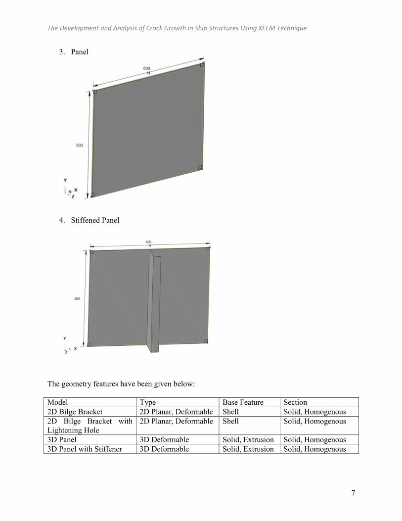
3. Panel
4. Stiffened Panel
The geometry features have been given below: Model Type Base Feature Section 2D Bilge Bracket 2D Planar, Deformable Shell Solid, Homogenous 2D Bilge Bracket with Lightening Hole
2D Planar, Deformable Shell Solid, Homogenous
3D Panel 3D Deformable Solid, Extrusion Solid, Homogenous 3D Panel with Stiffener 3D Deformable Solid, Extrusion Solid, Homogenous

The Development and Analysis of Crack Growth in Ship Structures Using XFEM Technique
8
Section 3: Development of Finite Element Meshes
1. Bilge Bracket Mesh
2. Bilge Bracket with Lightening Hole Mesh
3. Panel Mesh
The Development and Analysis of Crack Growth in Ship Structures Using XFEM Technique
9
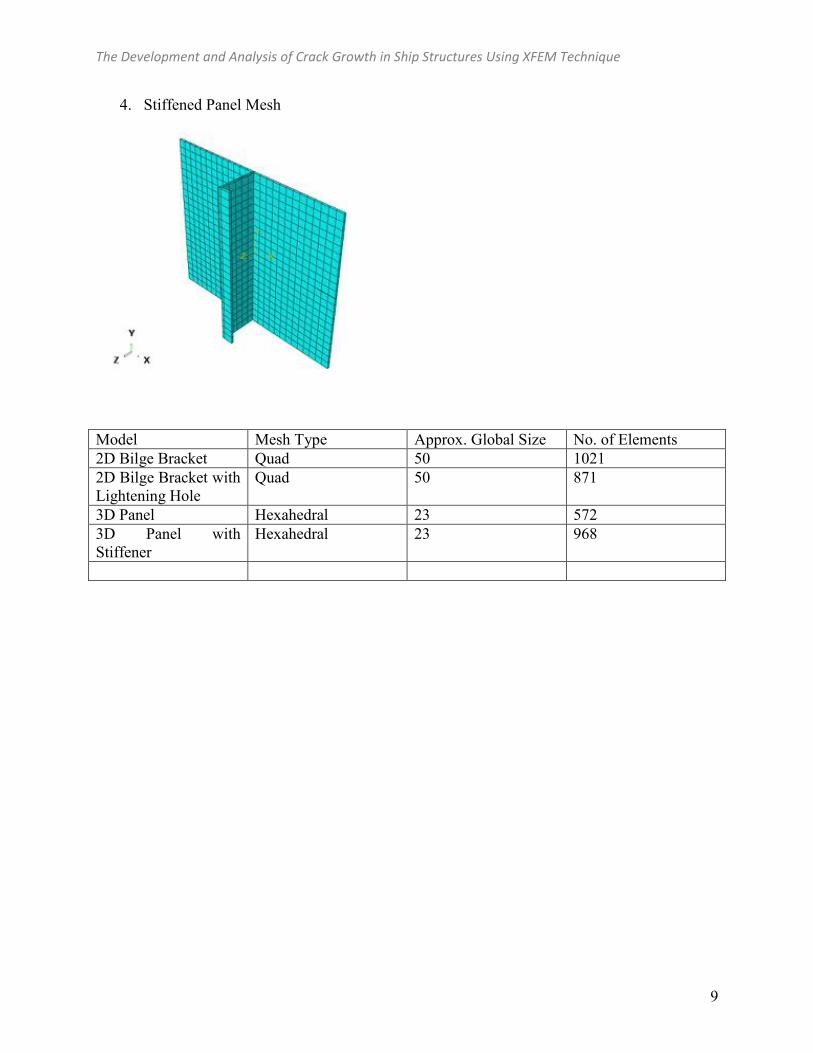
4. Stiffened Panel Mesh
Model Mesh Type Approx. Global Size No. of Elements 2D Bilge Bracket Quad 50 1021 2D Bilge Bracket with Lightening Hole
Quad 50 871
3D Panel Hexahedral 23 572 3D Panel with Stiffener
Hexahedral 23 968
The Development and Analysis of Crack Growth in Ship Structures Using XFEM Technique
10
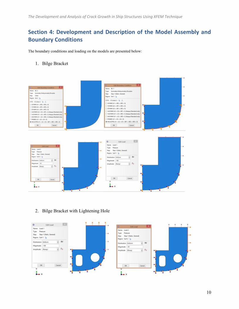
Section 4: Development and Description of the Model Assembly and Boundary Conditions The boundary conditions and loading on the models are presented below:
1. Bilge Bracket
2. Bilge Bracket with Lightening Hole

The Development and Analysis of Crack Growth in Ship Structures Using XFEM Technique
11
3. Panel
4. Stiffened Panel

The Development and Analysis of Crack Growth in Ship Structures Using XFEM Technique
12
Model Mesh Type Approx. Global Size No. of Elements 2D Bilge Bracket Quad 50 1021 2D Bilge Bracket with Lightening Hole
Quad 50 871
3D Panel Hexahedral 23 572 3D Panel with Stiffener
Hexahedral 23 968
The Development and Analysis of Crack Growth in Ship Structures Using XFEM Technique
13
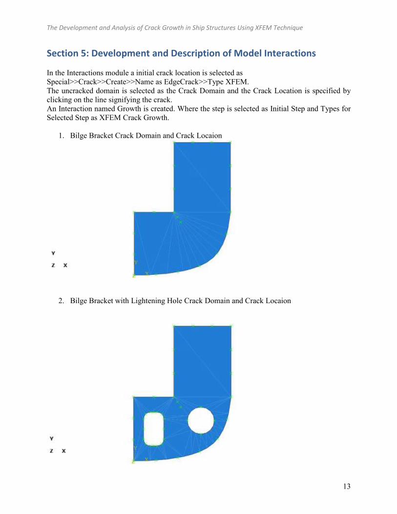
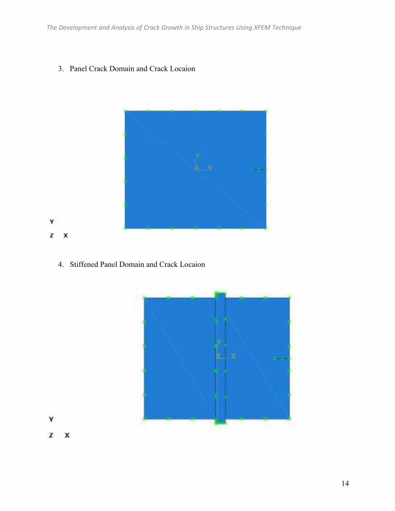
Section 5: Development and Description of Model Interactions In the Interactions module a initial crack location is selected as Special>>Crack>>Create>>Name as EdgeCrack>>Type XFEM. The uncracked domain is selected as the Crack Domain and the Crack Location is specified by clicking on the line signifying the crack. An Interaction named Growth is created. Where the step is selected as Initial Step and Types for Selected Step as XFEM Crack Growth.
1. Bilge Bracket Crack Domain and Crack Locaion
2. Bilge Bracket with Lightening Hole Crack Domain and Crack Locaion
The Development and Analysis of Crack Growth in Ship Structures Using XFEM Technique
14
3. Panel Crack Domain and Crack Locaion
4. Stiffened Panel Domain and Crack Locaion

The Development and Analysis of Crack Growth in Ship Structures Using XFEM Technique
15
Section 6: Analysis of Finite Element Model The analysis steps properties are given below for all the simulation. For 3D case since there are larger nonliniearities involved in the simulation, the maximum number of iterations have been increased and
Model Step Time Period
Maximum number of increments
Initial increment
size
Minimum increement
size
Maximum increment
size 2D Bilge Bracket
Static, General 1.00 1000 1.00 1E-005 1.00
2D Bilge Bracket with Lightening
Hole
Static, General 1.00 1000 1.00 1E-005 1.00
3D Panel Static, General 0.42 100000 0.001 1E-020 0.01
3D Panel with Stiffener
Static, General 0.42 100000 0.001 1E-020 0.01

The Development and Analysis of Crack Growth in Ship Structures Using XFEM Technique
16
Section 7: Summary of Major Findings Case 1: After running simulation of the 2D bilge plate it has been seen that the crack has propagated through the initial crack location. When comparison was made between the blige plate with and without lightening hole it has been seen the stress at crack tip is 3.5 time more in case of place with lightning hole.
The Development and Analysis of Crack Growth in Ship Structures Using XFEM Technique
17
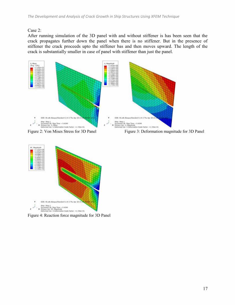
Case 2: After running simulation of the 3D panel with and without stiffener is has been seen that the crack propagates further down the panel when there is no stiffener. But in the presence of stiffener the crack proceeds upto the stiffener bas and then moves upward. The length of the crack is substantially smaller in case of panel with stiffener than just the panel.
Figure 2: Von Mises Stress for 3D Panel Figure 3: Deformation magnitude for 3D Panel
Figure 4: Reaction force magnitude for 3D Panel

The Development and Analysis of Crack Growth in Ship Structures Using XFEM Technique
18
Figure 5: Von Mise Stress for Panel with stiffener Figure 6: Deformation Maginutede for Panel with stiffener
Figure 7: Reaction Force magnitude for Panel with stiffener

The Development and Analysis of Crack Growth in Ship Structures Using XFEM Technique
19
Comparing the Load-Displacement curve of panel with and without stiffeners it has been seen that adding a stiffener has increased the strength of the panel by about 21%.
Figure 8: Load Displacement Curve of panel with and without stiffener. Effect of thickness has also been investigated. For solid panel it has been seen that increasing thickness has decreased in strength gain, which goes against experimental results. So this phenomena needs further investigating. For panels with stiffeners it has been seen that adding 1mm extra thickness does not result in significant strength gain.
(a) (b) Figure 9: Load Displacement Curve of (a)panel (b) panel with stiffener for different thickness.

The Development and Analysis of Crack Growth in Ship Structures Using XFEM Technique
20
Section 8: Works Cited
[1] IACS. Common structural rules for double hull oil tankers. London: International Association of Classification Societies; 2006. /http://www.iacs.orgS.
[2] Dexter, RJ, Mahmoud, HN. Predicting stable fatigue crack propagation in stiffened panels. Ship Structure Committee, U.S. Coast Guard, Report No. SSC-435; 2004. /http://shipstructure.orgS.
[3] Paik JK, Satish Kumar YV, Lee JM. Ultimate strength of cracked plate elements under axial compression or tension. Thin-Walled Structures 2005;43:237–72.
[4] Paik JK, Satish Kumar YV. Ultimate strength of stiffened panels with cracking damage under axial compression or tension. Journal of Ship Research 2006;50:231–8.
[5] Smith CS, Davidson PC, Chapman JC, Dowling PJ. Strength and stiffness of ships’ plating under in-plane compression and tension. Transactions of the Royal Institution of Naval Architects 1988;130:277–94.
[6] Margaritis, Y. Analysis of cracked stiffened panels under uniaxial compression with finite elements. MSc thesis. National Technical University of Athens; 2007.
[7] Belytschko, T., Gracie, R., Venture, G. (): a Review of extended/generalized finite element methods for material modelling. Modelling and Simulation in Materials Science and Engineering, vol. 17, No 4, 2009, pp. 043001.
[8] ABAQUS Analysis User’s Manuals, versions 6.8; 2008 and 6.9; 2009.