Embed Size (px)
Citation preview

MDESIGN for Mathcad – Current calculation knowledge for
mechanical engineering 78 Work sheets
Brief description of Contents,
Calculation Basis
and Scope

Engineers require up to date calculation knowledge
The Mathcad design libraries presently hold hundreds of standardized calculation methods, formulas and reference tables for tasks in almost all technical disciplines. Designers and product developers get access to scientific fundamentals, indispensable for their work. In addition to this general knowledge, engineers require calculation and analysis functions that are subject to the continuous technical progress. This knowledge growth is documented and harmonized by the standardization work of DIN, ISO and other organizations. Furthermore the corresponding design and construction procedures and their derived IT tools need to be regularly updated. MDESIGN, the widely used calculation library for mechanical engineering, offers this important service of actualization and knowledge dispersion. And MDESIGN is now also available as an application for Mathcad ®. “MDESIGN for Mathcad” combines the unique Mathcad functions with the technical and scientific content of MDESIGN. This content does not only get extended with every update, it is additionally adapted to the latest standard.

MDESIGN and Mathcad in Mechanical Engineering
In recent years Mathcad has acquired the reputation of a universal calculation environment for technical scientific applications. While Excel´s functionality is better suited for simpler problems, Mathcad addresses complex calculations that are often encountered in engineering. Mathcad furthermore allows you to program complex correlations without particular programming knowledge. This makes Mathcad a preferred tool in design and product development. However, Mathcad has been devised as a tool for individual programming and therefore lacks many standard calculations used in
design and specification. This gap is now closed by MDESIGN for Mathcad.
MDESIGN is a comprehensive library with technical design and calculation methods. The software modules support the design engineer in the sizing, optimization, verification and documentation of the components he has developed. They represent national and international standards and norms, making an important contribution to quality assurance of development processes and design results. MDESIGN calculations contain not only basic and standards oriented content with the goal of a broad use in companies but also a number of general features. Examples for these general features are the procedures for determining temperature and size dependent material characteristics, capturing and defining load spectra, generating input variations and input fields and two- and three-dimensional output graphics.
Unlike Mathcad, MDESIGN does not put the emphasis on the user-oriented acquisition and modification ability of the calculation through the designer. The main goal is the circulation of standardized algorithms, data and information through internal calculation departments as well as external service providers. Algorithms and procedures implemented in MDESIGN may include tens of thousands of programming code lines. Therefore they undergo a strict quality assurance process, certified by DIN ISO 9000. With the publication of selected calculations as Mathcad worksheets, MDESIGN gradually expands its repertoire of technical-scientific standard applications, especially into those areas where standard calculations are indispensable.
Designing new calculation procedures.
New tasks in engineering often lead to the alteration of calculation procedures. They are almost always based on already public approaches, but clearly differ in their operational sequence from previous solutions. In most cases there is no available software on the market for these applications. Mathcad worksheets with their tried, tested and transparent content are often an excellent basis for the design of such calculation sequences, especially, when the worksheets can be used as task-specific operation modules. Because in this case the definition of even complex algorithms is constrained to representing the system contexts and a new user interface. MDESIGN for Mathcad applies the object-oriented operating principle of Mathcad and considers the Mathcad worksheets from the outset as calculation library modules that are capable of being linked directly together. Calculation results can moreover be saved in a project database and are accessible herein. The possibility to utilize the compiled worksheets including all equations, entries, intermediate results and references fulfills the requirements of ISO 9001 relating to the traceability of all procedures and results.

MDESIGN for Mathcad with inherent databank
Technical calculations are to a large extent based on empirical information obtained through measurements, observations and damage symptoms that have been processed into tables, charts, and formulas with the help of mathematical procedures. Calculations therefore almost always have features, coefficients, and factors that are in turn dependent on numerous conditions. If they are not to be determined manually or visually out of diagrams but computer aided, functional relationships and a sufficient database must be available. The clear arrangement of all conversion factors, coefficients and variables in a service database furthermore ensures maximum transparency in the nomenclature of the system.
As the designing of standard parts is one of the main tasks of the design engineer the dimensions and characteristics of standard parts must be available during the design calculations and examinations. The maintenance of this data and their direct connection to the design environment therefore requires a powerful standard parts database.
A further example for the necessity of a database is the not to be neglected influence of material characteristics on the calculation of machine elements. Only if the standard properties of a material are known, the behavior under operating conditions can be predicted by empirical functions on the basis of operating temperature, size, shape and surface of a work piece. For this purpose a material database is essential.
Outline of benefits and features of MDESIGN for Mathcad
• MDESIGN for Mathcad ensures conformity to standards for the dimensioning and examination of machine elements
• MDESIGN for Mathcad delivers important mathematical as well as mechanical formulas and procedures for engineering
• MDESIGN for Mathcad endorses the unification of calculation applications throughout the entire company
• MDESIGN for Mathcad establishes a high degree of transparency for calculation and documentation
• MDESIGN and Mathcad permits an unprecedented interaction between the user and the calculation sequence
• MDESIGN for Mathcad establishes a quick and straightforward use of the contents for other assignments
• MDESIGN for Mathcad provides current standards on a regular basis for customers in case of a subscription
Licensing, prices and scope of services
MDESIGN for Mathcad is available as a single user or group license. Licenses can be obtained through the Internet via download.
To download the package, the buyer receives an access code to his customer account after having paid the purchase price. At this point he can download and install the software. After the installation the customer receives an activation code. This permits the utilization of all the shared databases and worksheets in accordance to the purchased license.

By purchasing the customer acquires the right to call the hotline up to three times. Emails to the hotline are unlimited. Answers are restricted to technical questions concerning installation and program development. Questions regarding the technical-scientific content and its application may be posed in writing; an obligation to answer does not exist.
No liability is accepted for the content of the work sheets. Indicated deficiencies are corrected in the process of program development. It is emphasized that the work sheets allow changes and therefore alone there can be no guarantee. In case of alterations the license owner must assume the responsibility to make sure the quality assurance of the work sheets is secured.
The worksheets represent the technical scientific standard valid at the time of publication. The standard is modified more or less quickly depending on the progress of standardization and technical development. There is no entitlement to such modifications of the worksheets. However it can be acquired with the purchase of an update or a service contract.
Prices Modules Price
License MDESIGN for Mathcad single license 78 899 €
Subscription All Updates, technical hotline 169 €/year
Consulting expert consultation by an engineer, technical calculations, worksheet development 89 €/hour
Please note that MDESIGN for Mathcad is not yet compatible with Mathcad prime.

The contents of „MDESIGN for Mathcad“ Machine element calculations following DIN and ISO
English Edition - October 2010
1. Materials 1.1 Properties of 160 materials
With the following program the standardized parameters can be determined for 160 materials from 13 different groups (from general unalloyed structural steel to aluminum alloys).
1.2 Material properties according to FKM
With the following program the relevant material data can be determined for non-welded building parts. Hereby, the standard blank or specimen values of the ultimate strength RmN and the yield point RpN are the basis. During the conversion of material data, the technological dimension factors, the anisotropy factor as well as temperature factors are taken into consideration. After material selection the material properties are automatically read out of the database and included in the calculation.
Note: The term "yield point" is used as a general designation for 0,2 % yield strength or yield point!
Calculation basis:
The groundwork calculation for the present module are stated in the FKM guideline "Rechnerischer Festigkeitsnachweis für Maschinenbauteile" (Calculated proven bearing capacity for machine building parts), 5., revised edition of 2003.
2. Shafts and Axles
2.1 Notch factor - Grooved shafts
With the following program based on the groundwork calculation of Roloff/Matek;
Maschinenelemente the design factors for grooved shafts can be calculated with the help of form factors.
Groundwork Calculations The groundwork calculation are described by Roloff/Matek, Maschinenelemente, Vieweg
Publishing House
Scope of the Program The permissible scope is defined by the following factors:
Radius - diameter ratio : with 2
)( dDt −=
Diameter ratio::
2.2 Notch factor - Reduced Shafts
r
t0≥ 03,
d
D0≤ 98,

With the following program based on the groundwork calculation of Roloff/Matek; Maschinenelemente the design factors for reduced shafts can be calculated with the help of form factors.
Groundwork Calculations
The groundwork calculation are described by Roloff/Matek, Maschinenelemente, Edition Vieweg
Scope of the Program
The permissible scope is defined by the following factors:
Radius - diameter ratio : with 2
)( dDt −=
Diameter ratio:
2.3 Notch factor – Splined shafts
With the following program based on the groundwork calculation of Roloff/Matek; Maschinenelemente the design factors for splined shafts can be calculated with the help of form factors.
Groundwork Calculations
The groundwork calculations are described by Roloff/Matek, Maschinenelemente, Edition Vieweg.
2.4 Notch factor – Parallel key notches With the following program based on the groundwork calculations of Rollof/Matek,
Maschinenelemente the design factors for shafts with parallel key notches can be calculated with the help of form factors.
Groundwork Calculations
The groundwork calculations are described by Roloff/Matek Machineelemente, Edition Vieweg
2.5 Notch factor - Cross bored shafts The purpose of this program is to calculate the design factors of crossed bored shafts with the
help of form factors, based on the theories of Roloff/Matek Machine elements.
Groundwork Calculations The groundwork calculations are described by Roloff/Matek Machineelemente, Edition Vieweg 2.6 Torsion tension in a shaft This program calculates the stress of a shaft due to rotation.
2.7 Design diameter for axles and shafts This program enables the rough calculation of a designed diameter for shafts and of pure
bending for axes. Since the permissible stresses are known or guide values were established by selecting the
material, a guide diameter is determined on the basis of the type of bending and torsion stress. Additionally, it is possible to differentiate between solid and hollow shafts.
Basis: Reference Book Roloff / Matek 16th Edition, Chapter 11.2.2
2.8 Damaging equivalent strain with complex loads (forces, torsions)
r
t0≥ 03,
d
D0≤ 98,

The purpose of this program is to determine the damage equivalent strain amplitudes, taking in account the load spectra of shafts and axles.
Groundwork Calculations
The calculation is based on the following ground works: DIN 743 of October 2000, FVA - Directive Calculation for load capacity of shafts and axles, a supplement to DIN 743, from May 2004.
Scope of the Program:
When in the following comments are made about shafts they also apply analogous for axles. The requirements of DIN 743 are effective, with the exception of the extensions on the fatigue and engineering strength (collective load).σ ADK must be determined according to DIN 743. The above relations are valid for normal stresses (bending, tension/pressure) and analogously for torsion unless explicitly stated otherwise. To maintain the external shape of fatigue evaluation proof to DIN 743, the damage equivalent constant tension is determined from the given load spectrum and the resulting collective tension (continuous). For this purpose, the hypotheses “Miner original method”, “Miner fundamental method”, “Miner expand method” and “Miner consistent method” are selectable.
2.9 Damaging equivalent strain with complex loads (Stress)
(See 2.8)
3. Bevel connections and clutches 3.1 Tapered connections
With the following program based on the groundwork calculations of Roloff/Matek Maschinenelemente, tapered connections can be dimensioned. Deviated cones can also be calculated using DIN 254. The module Tapered Connections has altogether 3 operations at its disposal: Examination of the tapered connection, Analysis of the maximum transferable torque, Analysis of the necessary tapered length Lmin.
Scope:
The program assumes that the angles of incidence for the outer- and inner section are the same size and they exhibit no deviations due to manufacturing conditions.

3.2 Parallel key connection- Method B
The strength examination of parallel keys used in shaft-hub connections with reference to DIN 6892- "Calculation and Design of Keys, Issue November 1998" can be executed with these work sheets. The examination of the required strength of parallel key connection in decreasing, increasing and charging torques, is the determination of the effective surface pressure between the key and the respective keyway wall on the shafts. This pressure may not exceed the permissible limiting values of the respective material characteristics. The determination of key strength for a parallel key connection is exclusively based on the dimensions and groove depths provided in DIN 6885 and DIN 6892. The key geometries, depending on the given shaft diameter, can be retrieved by the calculation program from a technical file taken according to DIN 6885. The strength examination of the shaft for torsion and bending loads according to the nominal stress concept is not included in this calculation module.
Calculation Basis
The calculation of the key connection is based on "Calculation and Design of Keys" following DIN 6892, November 1998, Method B and Method C.
The following DIN standards were used:
- DIN 6885 Sheet 1, Issue November 1998, Parallel Keys, keyways, high type
- DIN 6885 Sheet 2, Issue December 1967, Parallel keys, keyways, high type for machine tools
- DIN 6885 Sheet 3, Issue February 1956, Parallel keys low type
Scope
This program "Parallel Key Connections" follows DIN 6885 Sheet 1, DIN 6885 Sheet 2, DIN 6885 Sheet 3. Non-standardized keyway dimensions not following DIN 6885 can still be calculated from the key choice "Open input". However, the strength determination then does not correspond to DIN 6892!
3.3 Parallel key connection - Method C1 (See 3.2)
3.4 Parallel key connection - Method C2 (See 3.2)
3.5 Non engaging clutch (Dimensioning)
With the given program elastic shaft couplings can be dimensioned, based on the calculation groundwork of DIN 740 T2, for the most unfavorable type of load.
Pre-dimensioning If no working data like load, moment of resistance or moments of inertia of the moving
masses are present, a pre-selection should be carried out, the required clutch size is first determined using the rated transmitted torque of the load side. Thereby, the required entries are limited to a minimum.
Scope Non-engaging, torsion rigid and bending elastic clutches as well as torsion and bending elastic
clutches can be considered in different embodiments. The calculation of the required clutch size is carried out taking into account that the strength of elastic coupling elements decreases under temperature influence. Furthermore, due to factors, which are specified so as if they would cause a change of the coupling load to simplify the design.
Calculation basis: DIN 740 T2, and technical book Roloff/Matek 17. Edition, Chapter 13.2.6
3.6 Dimensioning of switchable clutches
The clutch calculation for the most unfavorable load type is based on the groundwork calculations of DIN 740 T2 and originates from Fachbuch Maschinenelemente Roloff/Matek, 17th edition. Predimensioning If no working data like load, moment of resistance or moments of inertia of the moving masses are present, a pre-selection should be carried out, the required clutch size is first determined using the rated transmitted torque of the load side. Thereby, the required entries are limited to a minimum. Scope Non-engaging, torsion rigid and bending elastic clutches as well as torsion and bending elastic clutches can be considered in different embodiments. The calculation of the required clutch size is carried out taking into account that the strength of elastic coupling elements decreases under temperature influence. Furthermore, due to factors, which are specified so as if they would cause a change of the coupling load to simplify the design.
Calculation basis: DIN 740 T2 and technical book Roloff/Matek 17. Edition, Chapter 13.2.6
4. Journals, Ball and Roller Bearings
4.1 Ball and Roller Bearings (with load spectrum)
With the following program the nominal lifetime of angular contact ball bearings can be calculated. A static load is to be assumed if only a small number of rotations or pendulum movements occur. In the case of a dynamic load the dynamic equivalent load and the reference number of rotations must be stated.
The influence of temperature effects and bearing cleanliness cannot be accounted for. The calculation is always done for a single bearing. The calculation of bearing combinations is not possible.
Calculation basis: The calculation is based on the following: DIN ISO 76 October 1988, DIN ISO 281 of November 2006, DIN ISO 281/A2 in September 2001, Amendment 2, lifetime adjustment xyz, DIN 1993 and DIN 623-1 May 623-2 June 2000, DIN 51 519 of August 1998, Roloff / Matek machine elements / design calculation standards; 18 Edition, Vieweg & Sohn Verlagsgesellschaft mbH, Braunschweig / Wiesbaden, 2009; Brändlein, Eschmann, Hasbargen,

Weigand: The Rolling practice / manual for the calculation and design of bearing. United publishers GmbH, Mainz, 1995.
Scope:
The following types of bearings can be calculated: ball and roller bearings.
4.2 Ball and Roller Bearings (without load spectrum) (see 4.1)
4.3 Radial Journals (Detailed calculation)
This program computes design values for stationary loaded radial journal bearings. A variety of lubrication methods is considered, such as lubricating hole, lubricating groove and lubricator in different arrangements.
For a specified bearing geometry (bearing diameter, bearing width, bearing clearance), a specified stationary applied bearing load (force, number of rotations) and a specified lubricant viscosity (viscosity class, lubricant temperature) a steady minimum clearance width is computed. It is compared with a specified permissible clearance width. Bearing friction and the lubricant consumption are computed in addition to the minimum clearance width. Applying a heat balance, the steady stationary bearing temperature is calculated using an approximation. It is also compared with a maximum permissible bearing temperature.
If the diameters of the shaft and the bearing shell are entered with tolerances the computation
mentioned above is carried out for the minimum clearance, for the mean bearing clearance and for the maximum clearance. With this additional level of detail, the designer can evaluate the variance of the bearing capacity as a result of the variance of component dimensions.
Calculation Base The suggested computation is founded on the following documentation: DIN 31 652 Part 1 from April 1983; Gleitlager; Hydrodynamische Radial-Gleitlager im stationären Betrieb;
4.4 Radial Journals (Simple Calculation) (see 4.3)
4.5 Axial Journals With the following program according to DIN 31 654, hydrodynamic axial journals in stationary operation can be calculated and specified. The Axial Journals module has 2 operations at its disposal. The actual application parameter will automatically be recognized by the program. The following operations are described in short: - Calculation of a bearing with heat conduction through convection - Calculation of a bearing with heat conduction through lubrication

Groundwork Calculations The design of the hydrodynamic axial journal will be run on the basis of DIN 31653, July 1986 edition. The following DIN specifications will also be utilized: - DIN 31 654 , part 2
Scope of the Program The calculation is valid for axial journals with fully integrated splined and grooved surfaces, for which the ratio of the splined surface length, lk to the segment length, l , is desired. The program is restricted to the steady range, (also from permanent danger condition areas) in which the loading and angular speeds of all rotating parts remain constant.
5. Springs 5.1 Belleville springs – Static examination
With the following work sheets axially loaded Belleville springs can be examined for static and dynamic loading with applications as single springs, as Belleville spring banks or Belleville spring columns.
For the examination of the Belleville spring column, spring combination and spring mass the loading condition are to be specified. The definition of the loading condition results from the application of the spring strength or the accompanying spring range.
The calculation results can be described graphically (spring diagram).
Groundwork Calculations
The groundwork calculations for the module Design of Belleville Springs is described by DIN 2092, edition September 1990 edition and DIN 2093, September 1990 edition.
The following DIN specifications will also be utilized: DIN 2098, part 1, edition December 1984, DIN 17221, edition December 1988, DIN 17222, edition August 1979, DIN 17224,
5.2 Belleville springs – Dynamic examination (see 5.1)
5.3 Tension springs (static load)
With the following work sheets cold and hot formed cylindrical extension springs made of wire and rods, which are axially loaded, can be dimensioned and examined.
The examination of extension spring requires the knowledge of the geometry data as well as the loading data. The definition of the stress state can be effected by entering the spring forces, range and length.
Groundwork calculations
The groundwork calculations for the module design of extensions springs are described by DIN EN 13906-2:2001. The following further DIN specifications will also be utilized: DIN EN 10270-1 edition 12/2001 patented drawn unalloyed springs steel wire, DIN EN 10270-2 edition 12/2001 oil tempered spring steel wire, DIN EN 10270-3 edition 08/2001 stainless spring steel wire, DIN 2099-2 edition 05/2004.

5.4 Tension springs (dynamic load) (see 5.3)
5.5 Compression Springs DE – (static load)
The basis of the examination is the DIN EN 13906-1 for „Berechnung und Konstruktion von Druckfedern.“ Two cases of load can be computed: (quasi-) static load and nominal cyclic load. Two different possibilities of the end coil design are selectable. With the computation of the spring stroke until buckling, five different cases of buckling (bearing of the spring ends) are differentiated.
5.6 Compression Springs – (dynamic load) (see 5.5)
5.7 Helical Compression Springs US This module calculates the properties of helical compression springs according to Mott (Machine Elements in Mechanical Design, fourth edition 2004).
5.8 Torsion Springs With the following program cylindrical torsion springs with linear characteristics of round wire with constant diameter can be calculated.
Groundwork Calculations
The groundwork calculations for the module Design of Torsion Springs are from the DIN 2088, Edition December 1988.
Scope of Program
The scope of cold formed torsion Springs is according to DIN 2194 and as follows: Wire diameter: d : 0 ... 17 mm Spring index: w : 4...20 Working temperature: T : -30 ... 240° Spring bank length: lk0 : σ 630 mm Average coil diameter: D : σ 340 mm Number of coils: n : σ 2
5.9 Torsion Bar Springs With the following program cylindrical torsion bar springs with a linear characteristic can be calculated. The design of torsion bar springs will be done according to the following theory:
- Ratio Radius of curvature (cavetto) to bar diameter: d
- Clamp length lk=0.5df
- Ratio diameter of root circle (head profile) to bar diameter:
σ = df/d=1.3 (square head, geared head)
σ = df/d=1.25 (hexagonal head)
The Design of Torsion Bar Springs Module has four different ways of calculation, which are automatically recognized by the module according to the current input:
- Geometry calculation with handicap of max. and min. Standard Torque, and Extension Angle - Geometry calculation with handicap of max. and min. Standard Torque and Spring Rate - Geometry calculation with handicap of Spring Rate and Extension Angle
- Geometry calculation with handicap of Length of Torsion Bar Spring and Bar Diameter The application of Radius of curvature, R is optional. Groundwork Calculations
The groundwork calculations for the Design of Torsion Bar Springs Module come from DIN 2091, June 1981 Edition.
In addition the following DIN specifications will be utilized:
- DIN 5481, Edition January 1952 (Kerbverzahnungen)
- DIN 17221, Edition December 1988 (Warmgewalzte Stähle für vergütbare Federn)
- DIN 32712, Edition March 1979 (Polygonprofil P4C)
Scope of the Program
The scope of the program is dependent according to DIN 2091 as follows:
static, dynamic loading Design of Torsion Bar Heads:
- square head (DIN 32712)
- hexagonal head
- geared head acc. to DIN 5481
Head-/ Bar- ration σ: >=1.3 Ô square head, geared head )
>=1.25 ( hexagonal head )
Place before σ: 0.02
Operational Temperature T: 30° ... 240 °C
Clamp length lk: 0.5df <lk <1.5df
Diameter area d: 10 ... 60 mm
Radius of curvature / bar diameter: 1<=R/d<=50
Notice: When using cold-formed torsion bar springs it is useful to consult the spring manufacturer.
5.10 Elastic Spring Materials This module carries out the service functions and is designed to simplify the process of adding and changing the material parameters and deleting materials of elastic springs in the database of the calculation “Tension Springs” and “Compression Springs”. This module operates with the following tables of the user database: - Springs: Materials general table - Springs: Materials Rm

6. Connecting elements
6.1 Cross bolts (Examination)
Cross bolts
With the following program based on the groundwork calculations from Roloff/Matek, Maschinenelemente it is possible to dimension and calculate cross bolts.
This program will take into consideration bolts without heads according to DIN 22340, (form A without splint holes and form B with splint holes), bolts with heads according to DIN 22341 (form B) as well as bolts with heads and thread studs according to DIN 1445.
The calculation program considers altogether 3 building cases which are of practical significance. The building cases do not need to be selected. The calculation runs parallel for all 3 building cases and the results will be stated separately after the calculation.
Calculation basis
The groundwork of the module is Roloff/ Matek, Maschinenelemente.
6.2 Cross bolts – Fork Width (see 6.1)
6.3 Cross bolts – Pole Strength (see 6.1)
6.4 Cross bolts – Operational Factor (see 6.1)
6.5 Cross bolts – Pole Force (see 6.1)
6.6 Cross bolts – Bolt Diameter (see 6.1)
6.7 Guiding Pins – Examination

With the following program based on the groundwork calculations Roloff/Matek, Maschinenelemente it is possible to dimension and calculate guiding pins.
Scope of the program
This program takes into consideration the bending stress at the point of support, as well as the existing contract pressure through the bending moment Mb and transverse force F.
This program does not take the existing shear stress at the point of support into consideration as this can be neglected according to experience.
6.8 Guiding Pins – Pin Diameter
(see 6.7) 6.9 Guiding Pins – Insertion Depth
(see 6.7) 6.10 Guiding Pins – Operational Factor
(see 6.7) 6.11 Guiding Pins – Lever Arm
(see 6.7) 6.12 Guiding Pins – Bending Force
(see 6.7) 6.13 Tensile loaded bonded joints
With the following program, based on the groundwork calculations of Roloff/Matek, Machine Elements, loaded bonded joints will be resolved. The calculation module has a technology file at its disposal, from which the joints and characteristic data can be taken. The work sheets have 4 operations at their disposal. The program automatically recognizes the actual application parameter from the calculation module. The following are descriptions of the operations in short: - Examination of the tensile loaded bonded joints
- Analysis of the minimum joint width bmin (with consideration of the wished safety St)
- Analysis of the minimum part thickness tmi (with consideration of the wished safety St)
- Analysis of the maximum traction Fmax (with consideration of the wished safety St) Calculation Basis: The module is based on the groundwork calculations of Roloff/Matek, Maschinenelemente, Vieweg Publishing House. The following DIN specifications will also be utilized: VDI 2229, Metal bonded joints, June 1979 Instructions for design and production Scope of the program The scope of the modules loaded bonded joints is determined according to Roloff/Matek, Maschinenelemente as follows: - Luting of identical materials (metal - metal) - Luting of different materials (non metal materials - metal materials) - Operational temperature: - 25°C … + 155°C - Joints according to VDI 2229 - Static and dynamic loading - Traction
6.14 Tangential loaded bonded joints

(see 6.13) 6.15 Torsion loaded bonded joints
(see 6.13) 7. Bolt Calculations 7.1 Bolt Calculation Design
With this software preliminary dimensioning of the bolt nominal diameter as well as the systematic calculation of joints with one cylindrical bolt can be carried out according to the guideline VDI 2230 Part 1: 2003-02.
All calculation procedures, including load and deformation conditions, are based on the single bolted joint model. Therefore all loads and sizes affecting the complete joint from the outside are to be reduced to a single bolted joint and are presumed to be known.
The program enables the user to compute multi-bolted joints, such as circular joint flanges. Note that the torque acting at the periphery is considered through the number of bolts on the pitch circle and through the loads per bolt resulting from it.
The calculation program utilizes databases making it possible to enter bolt sizes, different strength grades and materials of clamped parts on the input page directly.
All database tables can be customized according to the user`s needs (for example to include other standards).
Extreme operating conditions such as corrosion and impact loads cannot be considered.
Calculation basis: The calculation basis of this Bolt Calculation module is the guideline VDI 2230 Part 1.
7.2 Initially stressed bolt calculation With this software the systematic calculation of joints with one cylindrical bolt can be carried out according to the guideline VDI 2230 Part 1: 2003-02. Operating loads can be described as static as well as dynamic working forces FB . Additionally shear forces FQ and operating moments can be considered. The assembly initial stresses (FB and FQ) of the screw serve as the main criteria for the choice of the screw nominal diameter. All working loads affecting the connection and the affiliated results are exclusively for one bolt connections. These apply for a defined dimension of the joint area in the plane of the screw axle and the impact line of the work force. The calculation program utilizes databases making it possible to enter bolt sizes, different strength grades and materials of clamped parts on the input page directly. All database tables can be customized according to the user`s needs (for example to include other standards).
Note: The elastic resilience of clamped parts is presumed to be linearly variable. That is if the axial operating load exceeds the opening load, the resilience rises progressively and an opening joint is on hand. These parts cannot be computed by the given program. The aim of the guideline is to prevent a one-sided opening of the joint by the introduction of a sufficient minimum clamp load. Calculation basis: Roloff/Matek 17. Edition, Chapter 8.3.9

7.3 Bracket Connections (Examination)
This program enables you to calculate connections of parts similar to brackets (consoles) using Roloff/Matek, Maschinenelemente as a basis of calculation. Hereby, the load is considered through the bearing force F, the spacing la, in the form of the bending moment as well as the shear effect caused by F. For transversal loaded screws, the calculation is performed, as is the standard in steel construction, by regarding shearing and hole intrados pressure, though the external loads are mainly or completely absorbed by the friction grip. It is assumed that the transversal load n is distributed on all screws n evenly.
Calculation basis The basis of calculation for the module Bracket Connections is the reference book Roloff/Matek, Maschinenelemente, 16th edition.
7.4 Bracket Connection – (transmissible force) (see 7.3)
7.5 Bracket Connection – (diameter wanted) (see 7.3)
8. Tooth Systems, Gears 8.1 Spur gear- Examination of the geometry
With the following program based on the groundwork calculations DIN 3960, the geometry of spurs can be calculated.
Calculation basis The groundwork calculations for this module are described by DIN 3960, edition March 1987. The following DIN specifications will also be utilized: DIN 780 Module sequence for spur gears, DIN 867 edition February 1986, DIN supplement 1, edition July 1980.
8.2 Profile displacement of outer teeth With the following program, based on DIN 3992, the following profile parameters can be determined: - Axle distance a [mm] - Operating pressure angle - Profile displacement factor x1 pinion and x2 for wheel

The distribution of the total profile displacement factors xg is determined by the goal of the profile optimization: - Very high dedendum flank safety - High dedendum flank safety - Balanced gearing - High overlap factor - Very high overlap factor
8.3 Belt contact drive With the following program based on the groundwork calculations according to Roloff/Matek, Maschine Elements, the geometry and dimensions of the belt pulley can be calculated.
Scope of the program Consideration will be available for two-pulley-design in horizontal, perpendicular or helical arrangement.
8.4 Dimensioning of synchronous belts
The work sheet enables the dimensioning and calculation of synchronous belts for drives with two and more shafts. It is possible to select different belt types and belt spacings respectively from a database. The chosen value can be transferred directly to the calculation program.
Basis for calculation
Basis for calculation is Roloff/Matek Maschinenelemente, Vieweg Verlag.
Scope
The dimensioning is using current types of synchronous belts and spacing. It is possible to choose between belts made of Polychloroprene/Neoprene (CR) or Polyurethane (PU). On basis of the required belt length the program calculates the next possible standard belt length by using specified geometric data of the belt drive like position of pulley, distance of axles .
8.5 Roller Chains
The calculation module is based upon DIN ISO 10823 "Guidance on the selection of roller chain drives". This international standard refers to roller chains and chain wheels in accordance with ISO 606.
The selection procedures and the chain ratings in ISO 10823 provide for roller chain drives with a life expectancy of approximately 15 000 hours under the following conditions:
- Utilization of a suitable method of lubrication (as shown on the results page), - Use of a lubricating oil with a suitable viscosity class (table can be selected to be shown on
results page) - Centre distance measures between 30 and 50 times the chain pitch - Arc of contact of not less than 120° on the drive sprocket, - Usage of chain adjustment.
In ISO 10823 it is specifically recommended to consult with the supplier of the equipment intended to be used to ensure its suitability.
Basis: Calculation of Rollenr chains after DIN/ISO 10823

8.6 Cylindrical Worm Gear Pairs
With the following program the strength examination (pitting bearing capacity, root bearing capacity), safety against deflection, safety against temperature and wear bearing strength of cylindrical worm gear pairs will be calculated based on the groundwork calculations of DIN 3996 Method C.
Groundwork Calculations The groundwork calculations for the module cylindrical worm gear pairs are described by the following DIN specifications: - DIN 3974 Part 1, Edition November 1995 (Accuracy of worms and worm gears, general bases) - DIN 3974 Part 2, Edition November 1995 (Accuracy of worms and worm gears, tolerances) - DIN 3975 Edition October 1976 (Terms and definitions for cylindrical worm gears with shaft
angle 90°) - DIN 3976 Edition November 1980 (Cylindrical worms) - DIN 3996 Edition September 1996 (Calculation of load capacity of cylindrical worm gear pairs) - DIN 3998 Part 4, Edition September 1976 (Denominations on gears and gear pairs, worm gear pairs)
Scope of the Program The validity will be bounded by the following dimensions: - Cylindrical worm gear pairs with shaft angle 90° - Flank main form ZI, ZA, ZK, ZN, ZH, ZC
- Angle of action: 15°<= α <=25°
- Addendum modification coefficient: -1 < x < 1 - Topland thickness factor: cP1* = cP2* = 0.2 - Splash lubrication, injection lubrication
9. Linear technology
9.1 Power Screws The following program performs calculations for power screws based on the groundwork of Roloff/Matek, Machine Elements, compression, torsion strength, and examination of buckling.
Groundwork Calculations The groundwork calculations for the Power Screws module are described by Roloff/Matek, Machine Elements. The following DIN specifications will also be utilized: - DIN 103 trapezoidal threads - DIN 513 buttress threads
9.2 Linear guide (dynamic non stationary) With the following work sheet ball and roll circulate guides can be chosen and calculated. The entered details determine for which failure reason the calculation is to perform. Dependant on the selected failure reason the required input parameters are requested. Using the existing radial and tangential loads Fr and Ft the static equivalent load P0 is determined. With the static equivalent load and the static load C0 the Safety S0 is determined, which is compared to the entered requested Safety S0-req.
The dynamic equivalent load P is also determined using the existing radial and tangential loads. Depending on the dynamic equivalent load P the expected fatigue life is calculated. For non-stationary dynamic loads an equivalent load is determined for every single load case. Under consideration of the respective portion q of the total course the median equivalent load Pm is calculated.The total fatigue life is compared to the requested fatigue life L_rew.
Basis of Calculation -DIN 636 Part 2 from June 1993; Linear-Wälzlager; Dynamische und statische Tragzahlen; Profilschienen-Kugelführungen; -DIN ISO 281/A2 from September 2001; Rolling bearings - Dynamic load ratings and rating life Fatigue life; Change 2; Fatigue life coefficient axyz; -CAD Catalog Version 3.2 form company THK (Data carrier: CD-ROM); -INA-Catalog; -Rexroth-Bosch STAR Homepage; -Roloff/Matek: Maschinenelemente/ Normung Berechnung Gestaltung; 14. Edition, Vieweg& Sohn Verlagsgesellschaft mbH, Braunschweig/Wiesbaden, 2000
9.3 Linear guide (dynamic stationary) (see 9.2)
9.4 Linear guide (static) (see 9.2)
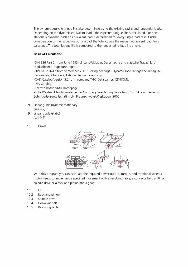
10. Drives
With this program you can calculate the required power output, torque, and rotational speed a
motor needs to implement a specified movement with a revolving table, a conveyor belt, a lift, a
spindle drive or a rack and pinion and a gear.
10.1 Lift 10.2 Rack and pinion 10.3 Spindle drive 10.4 Conveyor belt 10.5 Revolving table

11. General Mechanics 11.1 Statically determinate Beams
With this program you can calculate elastic deflections for simple loaded beams. For this purpose 12 loading cases of simple statically defined systems are available for selection. Furthermore it is possible to calculate the deflection for every point x along the beams as well as to display the entire bending line (load-deflection curve) by the function of ''parametric analysis'' over the beam length.
Calculation groundwork
The calculation groundwork for the calculation of the deflection of beams is taken from Dubbel Taschenbuch for Maschinenbau, 19th edition. Auflage.
11.2 Buckling of Rods
With this program you can calculate buckling of slim rods and verify them on safety against buckling. Four clamp cases can be considered. First of all, the program uses the Euler`s buckling equations to examine whether to calculate the elastic (Euler equations) or inelastic buckling (Tetmajer equations).
If the radio of slenderness σ is lower than the minimum ratio of slenderness the calculation is automatically performed for the inelastic buckling according to Tetmajer.
11.3 Hertzian Pressure - Sphere/Sphere
This program calculates two contacting solids and the resulting surface pressure values at their contact points according to the Hertz´s theory. Doing this you can differ between point und linear contacts of solids. You are facing a single contact point if you consider an all-round

convex solid. In contrast cylinders have an endless length in axial direction which is understood as linear contact.
Calculation base:
The base for calculating convergence and surface pressure for two touching elastic solids is the Hertz´s theory taken from Dubbel Taschenbuch für den Maschinenbau, 19th edition, as well as "Die Wälzlagerpraxis", 3rd edition of J. Brändlein, Vereinigte Fachverlage.
Scope of the Program: The condition of the application is that the solids are deformed only elastically and thus they do not exceed the limit of proportionality of materials. Accordingly, on account of a crushing stress acting on, no plastic elongations are permitted to appear in the contact surfaces. Additionally, only normal stresses occur in the thrust face but no shear stresses. The convergence (flattering) of both solids has to be small in proportion to the sizes of curvature.
11.4 Hertzian Pressure - Sphere/Plane (see 11.3)
11.5 Hertzian Pressure – Curved Solid/Curved Solid (see 11.3)
11.6 Hertzian Pressure - Curved Solid/Plane (see 11.3)
11.7 Hertzian Pressure - Cylinder/Cylinder (see 11.3)
11.8 Hertzian Pressure - Cylinder/Plane (see 11.3)
11.9 Polar Moment of Inertia The program analyzes the coordinates y and z of the polar center of gravity, the surface A, internal edge e , polar moment l , combined polar moment lyz , moment of resistance W, as well as the axis angle of evenly bounded surfaces. Curvilinear bounded surfaces can be calculated by the application of polygonal courses with adequate accuracy.
Definition of the axial intersection: The y - coordinate correlates with the horizontal axis. The z - coordinate correlates with the perpendicular axis.
The geometrical cross-section parameters can be defined related to different coordinate axes. Y- Z is a global system of coordinates, relating to which the cross-section is built up.
The position of the centre of gravity relating to the global coordinate system is predetermined by means of the parameters ys and zs. Consequently, Ys - Zs is a coordinate system being parallel to the global one and crossing the centre of gravity of the cross-section.
The axes Ys - Zs are central ones. The polar moments I ys and I zs relating to the axes Ys – Zs take on the smallest values from all moments of inertia relating to the axes being parallel to the axes Y - Z.
The main axes 1 - 2 are the coordinate system of the central axes crossing the centre of gravity
of the cross-section and being turned relating to the axes Ys - Zs by some angle α. The
product of inertia relating to the main central axes 1 - 2 is I12 = 0. The moments of inertia I1 and I 2 take on the maximum and the minimum values from all moments of inertia relating to the axes crossing the centre of gravity of the cross-section.
11.10 Beam Profiles

The program fulfills service functions and eases the addition and change of geometric profile parameters as well as the deletion of the profile in the profile databank that is used for "Beam Calculation" and "Moment of Inertia".
Note: Standard profiles that are part of the MDESIGN Databank and are included in the product installation may not be deleted or changed. It is only possible to change or delete profiles that were added to the databank by the user. On the basis of standard profiles it is possible to create new profiles under new names.
The program works with the following tables of the user databank:
- Strip steel, hot DIN EN 10058
- Equal leg angles DIN EN 10056-1
- Unequal leg angles DIN EN 10056-1
- I-beams, I-series DIN 1025-1
- I-beams, IPB-series DIN 1025-2
- I-beams, IPBI-series DIN 1025-3
- I-beams, IPBv-series DIN 1025-4
- I-beams, IPE-series DIN 1025-5
- Square, cold hollow sections DIN EN 10219-2
- Square, hot hollow sections DIN EN 10210-2
- Rectangular, cold hollow sections DIN EN 10219-2
- Rectangular, hot hollow sections DIN EN 10210-2
- Rounds, cold hollow sections DIN EN 10219-2
- Rounds, hot hollow sections DIN EN 10210-2
- Rod, hot DIN EN 10060
- T-steel, circular DIN EN 10055
- U-profile, incline shelf DIN 1026-1
- U-profile, direct shelf DIN 1026-2
- Square profile, hot DIN EN 10059
- Z-steel, hot DIN 1027
11.11 O-Ring Design With this program you can select radial outer sealing and radial inner sealing O-rings basing on DIN 3771-1. The output of all clearance spaces according to DIN 3771-5 and tolerances is done after determining an outer diameter of the building part. The available data record can be restricted in respect of the diameter ranges. Thus, a quick selection of an applicable O-ring is ensured.
The Contents of „MDESIGN for Mathcad“
English Edition – April 2011
Machine Elements-Calculation according to DIN and ISO
Properties of 160 materials, Material properties according to FKM, Notch factors – Grooved
shafts – Reduced Shafts – Splined shafts – Parallel key notches – Cross bored shafts, Torsion
stress in a shaft, Design Diameter for Axles and Shafts, Damaging equivalent strain with CL (F,
T) - Damaging equivalent strain with CL (Stress), Tapered connections, Parallel key connections
– Method B – Method C1 – Method C2, Ball and roller bearings – (with load spectrum) –
(without load spectrum), Calculation Radial Journals, (Detailed, Simple), Calculation Axial
Journals, Belleville Springs – Examination static – Examination dynamic, Tension Springs –
Examination static – Examination dynamic, Compression Springs – Examination static –
Examination dynamic-Examination US according to Mott, Torsion Springs-Examination, Torsion
Bar Springs-Examination, Elastic spring materials, Cross bolts – Bolt diameter – Fork width –
Pole strength – Operational factor – Pole force – Examination, Guiding Pins – Bending force –
Pin diameter – Insertion depth – Operational factor – Lever arm – Examination, Bonded joints –
Tensile loaded – Tangential loaded – Torsional loaded, Bolt Calculation – Bolt design – Initially
stressed bolt, Bracket Connections – Diameter – Transmissable force – Examination, Tooth
Systems, Gears –Spur gears geometry- Profile displacement of outer teeth –Belt drive –
Dimensioning of synchronous belts – Roller Chains – Cylindrical Worm Gear Pairs , Power
Screws, Linear guide – dynamic non stationary loads – dynamic stationary loads – static loads,
Drives – Lift – Rack and Pinion – Spindel drive – Conveyor belt – Revolving Table, General
Mechanics–Statically Determinate Beams–Buckling of Rods, Hertzian pressure - Sphere/Sphere -
Sphere /Plane - Curved solid /Curved solid - Curved solid /Plane - Cylinder/Cylinder -
Cylinder/Plane, Polar Moments of Inertia, Beam profiles 12 cases, Design O-Ring
TEDATA Gesellschaft für technische Informationssysteme mbH
Koenigsallee 45 44789 Bochum Germany
For more information visit us at
www.mdesign.info/mathcad.html