Embed Size (px)
Citation preview
MAROON-X: A Radial Velocity Spectrograph for the GeminiObservatory
Andreas Seifahrta, Julian Sturmera, Jacob L. Beana, Christian Schwabb,c
aUniversity of Chicago, USAbMacquarie University, Sydney, Australia
cAustralian Astronomical Observatory, Sydney, Australia
ABSTRACT
MAROON-X is a red-optical, high precision radial velocity spectrograph currently nearing completion and un-dergoing extensive performance testing at the University of Chicago. The instrument is scheduled to be installedat Gemini North in the first quarter of 2019. MAROON-X will be the only RV spectrograph on a large tele-scope with full access by the entire US community. In these proceedings we discuss the latest addition of thered wavelength arm and the two science grade detector systems, as well as the design and construction of thetelescope front end. We also present results from ongoing RV stability tests in the lab. First results indicatethat MAROON-X can be calibrated at the sub-m s−1 level, and perhaps even much better than that using asimultaneous reference approach.
Keywords: Gemini, radial velocity, echelle spectrograph, optical fibers, CCD, active fiber guiding, radial velocitystability, Fabry Perot etalon
1. INTRODUCTION
Radial velocities (RVs) dominated the first fifteen years of exoplanet science by delivering the first statisticalconstraints on planet occurrence around a wide range of stars. With the field of exoplanets now in its thirddecade, the RV technique remains at the forefront due to its continued unmatched sensitivity to planets aroundnearby stars and its important supporting role for other exoplanet detection techniques.
In terms of support for other techniques, RV follow-up measurements in support of ground- and space-based transit surveys are a critical component of the confirmation of candidate exoplanets and for their massmeasurements. With the successful TESS launch this past April and the upcoming launch of the EuropeanCHEOPS mission by the end of this year (2018), many new small transiting planets will be identified over thenext decade. This presents an enormous opportunity to expand our study of planetary statistics into the regimeof planet bulk compositions, with the RV method delivering the mass measurements of these objects. Thesemass measurements also become essential to select suitable targets for follow-up atmospheric studies using HST,Spitzer, and JWST and future direct imaging missions.
The RV technique is also a critical component of the near-term opportunity to study potentially habitableplanets orbiting M dwarfs, and in particular the very lowest-mass M dwarfs (those with M?< 0.3 M�). In contrastto solar-type stars, the habitable zones of these stars are close-in enough so that planets in this region have asignificant chance of transiting and would be feasible targets for transit spectroscopy observations to characterizetheir atmospheres. Although M dwarfs comprise the bulk of the stellar population in the solar neighborhood,they are intrinsically faint. Precision RV measurements of mid to late M dwarfs thus require a large size telescopeand an efficient spectrograph.
With the recent installation of ESPRESSO at the VLT,1 HPF at the HET,2 and IRD at Subaru,3 a newgeneration of fiber-fed, highly stabilized RV spectrographs has arrived at 8-10 -m class telescopes. In the comingyears, more instruments at large telescopes will become available, such KPF on Keck4 and iLocator on the LBT.5
However, none of these instruments offers unrestricted access to the entire US community.
Further author information: (Send correspondence to A.S.)A.S.: E-mail: [email protected], Telephone: 1 773 702 9877
arX
iv:1
805.
0927
6v1
[as
tro-
ph.I
M]
23
May
201
8
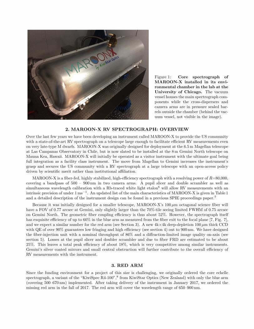
Figure 1: Core spectrograph ofMAROON-X installed in its envi-ronmental chamber in the lab at theUniversity of Chicago. The vacuumvessel houses the main spectrograph com-ponents while the cross-dispersers andcamera arms are in pressure sealed bar-rels outside the chamber (behind the vac-uum vessel, not visible in the image).
2. MAROON-X RV SPECTROGRAPH: OVERVIEW
Over the last few years we have been developing an instrument called MAROON-X to provide the US communitywith a state-of-the-art RV spectrograph on a telescope large enough to facilitate efficient RV measurements evenon very late-type M dwarfs. MAROON-X was originally designed for deployment at the 6.5 m Magellan telescopeat Las Campanas Observatory in Chile, but is now slated to be installed at the 8 m Gemini North telescope onMauna Kea, Hawaii. MAROON-X will initially be operated as a visitor instrument with the ultimate goal beingfull integration as a facility class instrument. The move from Magellan to Gemini increases the instrument’sgrasp and secures the US community with a RV spectrograph at a large telescope with an open-access policydriven by scientific merit rather than institutional affiliation.
MAROON-X is a fiber-fed, highly stabilized, high-efficiency spectrograph with a resolving power of R=80,000,covering a bandpass of 500 – 900 nm in two camera arms. A pupil slicer and double scrambler as well assimultaneous wavelength calibration with a Rb-traced white light etalon6 will allow RV measurements with anintrinsic precision of under 1 ms−1. An updated list of the main characteristics of MAROON-X is given in Table 1and a detailed description of the instrument design can be found in a previous SPIE proceedings paper.7
Because it was initially designed for a smaller telescope, MAROON-X’s 100µm octagonal science fiber willhave a FOV of 0.77 arcsec at Gemini, only slightly larger than the 70%-tile seeing limited FWHM of 0.75 arcsecon Gemini North. The geometric fiber coupling efficiency is thus about 52%. However, the spectrograph itselfhas exquisite efficiency of up to 60% in the blue arm as measured from the fiber exit to the focal plane [7, Fig. 7],and we expect a similar number for the red arm (see Section 3). A new 4k×4k deep-depletion 100µm thick CCDwith QE of over 90% guarantees low fringing and high efficiency (see section 4) out to 900 nm. We have designedthe fiber-injection unit with a nominal throughput of 86% and a diffraction-limited image quality on-axis (seesection 5). Losses at the pupil slicer and doubler scrambler and due to fiber FRD are estimated to be about25%. This leaves a total peak efficiency of about 18%, which is very competitive among similar instruments.Gemini’s silver coated mirrors and small central obstruction will further contribute to the overall efficiency ofRV measurements with the instrument.
3. RED ARM
Since the funding environment for a project of this size is challenging, we originally ordered the core echellespectrograph, a variant of the “KiwiSpec R4-100”,8 from KiwiStar Optics (New Zealand) with only the blue arm(covering 500–670 nm) implemented. After taking delivery of the instrument in January 2017, we ordered themissing red arm in the fall of 2017. The red arm will cover the wavelength range of 650–900 nm.

PR
IME
OP
TIC
S / M
AROO
N-X
1
1. Red C
amera, version 20170504
Figure 1: MA
RO
ON
-X Red C
amera + G
rism
VPHG + prisms
[Grism] RCM
1
RCM2
RCM3
RCM4
RCM5/W
indow
CCD
L4L3L2
VPH grism
L1
L5 = dewar window
CCD
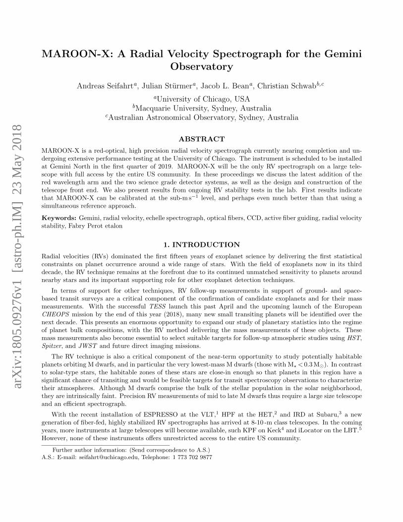
Figure 2: Optical design of the red camera and cross-disperser arm for MAROON-X. A dichroicand fold mirror (not shown here) steer the white pupil onto a VPH grism for cross-dispersion. The camera iscomprised of a triplet, a doublet and three singlet lenses. The last lens, L5, is made of fused silica and doublesas the dewar entrance window for the CCD cryostat. The camera has a long back-focal length of over 200mm.
The camera optics in the red arm posed some challenges, as the high anamorphic pupil compression of 1:3hinders an effective aberration compensation which is compounded by the longer orders (and, hence, wider angles)in the red camera compared to the blue camera. Consequently, even after a lengthy optimization procedure, theaverage spot sizes for the red camera are slightly larger than for the blue camera and the width of the 80% EEin dispersion direction ranges from 4µm to almost 20µm compared to an average slit width of 53µm.
The camera design by Damien Johnes (Prime Optics, Australia) uses a combination of five different Oharaglasses as well as fused silica (see Figure 2) and features a long back-focal length to ease the placement of theCCD cryostat next to the camera and cryostat of the blue arm. The last lens of the red camera (L5) is made offused silica and has a cylindrical surface facing the camera and a spherical surface facing the CCD detector. Itdoubles as the dewar entrance window for the CCD cryostat. All lenses have BBAR coatings with an averagereflectivity of R≤0.5%.
The cross-disperser is a VPH grism with similar characteristics as the one used in the blue arm. The VPHgratings are made by Kayser Optical Systems Inc. (KOSI). The blue VPH has 1,652 l mm−1, while the red VPHhas 1,161 l mm−1.
The camera and cross-disperser optics are currently in production and we expect delivery of the red arm bySeptember 2018. Integration with the spectrograph will be uncritical as the dichroic and red fold mirror arealready installed and the vacuum chamber of the spectrograph does not need be opened for the installation ofthe new optics.
4. SCIENCE GRADE DETECTOR SYSTEMS
For the same reasons as the delayed order of the red arm, we had to delay the order of our detector systemsuntil funding became available. In March 2017 we placed an order with STA Inc. to deliver two complete 4k×4kdetector systems based on their new STA4850 CCD. The detector systems include cryostats, Bonn shutters, andtwo water cooled Archon CCD controllers. We expect the delivery of the complete detector systems by August2018.
The STA4850 is a 4k×4k device with 15µm pixel size. It was designed specifically for MAROON-X as animprovement over the STA4150. It adds a dump drain and back bias features, and has pads along only twosides. The dump drain allows for fast flushing, and the back bias allows the device to be made on 30µm thickepitaxial silicon or 100µm thick bulk silicon for higher red quantum efficiency (QE).
The package is specifically designed for high resolution ultra stable spectroscopy. It has low thermal mass anddirectly integrates the temperature sensing and control with two different temperature control approaches.The
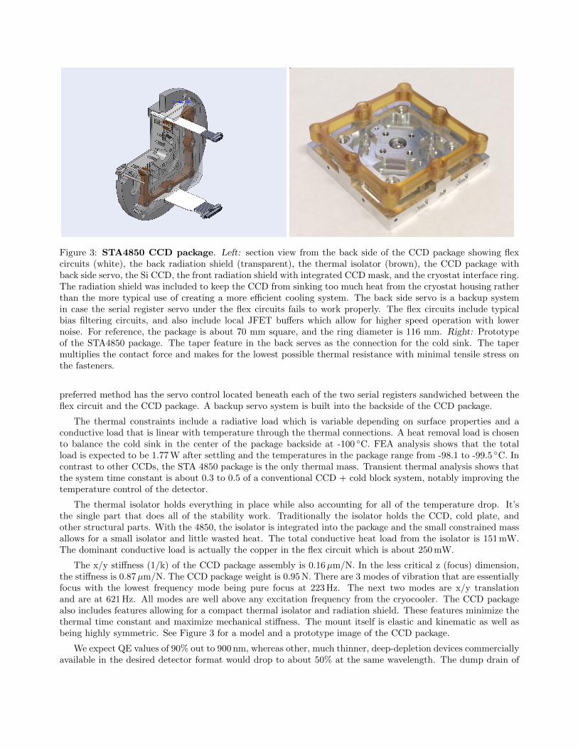
Figure 3: STA4850 CCD package. Left: section view from the back side of the CCD package showing flexcircuits (white), the back radiation shield (transparent), the thermal isolator (brown), the CCD package withback side servo, the Si CCD, the front radiation shield with integrated CCD mask, and the cryostat interface ring.The radiation shield was included to keep the CCD from sinking too much heat from the cryostat housing ratherthan the more typical use of creating a more efficient cooling system. The back side servo is a backup systemin case the serial register servo under the flex circuits fails to work properly. The flex circuits include typicalbias filtering circuits, and also include local JFET buffers which allow for higher speed operation with lowernoise. For reference, the package is about 70 mm square, and the ring diameter is 116 mm. Right: Prototypeof the STA4850 package. The taper feature in the back serves as the connection for the cold sink. The tapermultiplies the contact force and makes for the lowest possible thermal resistance with minimal tensile stress onthe fasteners.
preferred method has the servo control located beneath each of the two serial registers sandwiched between theflex circuit and the CCD package. A backup servo system is built into the backside of the CCD package.
The thermal constraints include a radiative load which is variable depending on surface properties and aconductive load that is linear with temperature through the thermal connections. A heat removal load is chosento balance the cold sink in the center of the package backside at -100 ◦C. FEA analysis shows that the totalload is expected to be 1.77 W after settling and the temperatures in the package range from -98.1 to -99.5 ◦C. Incontrast to other CCDs, the STA 4850 package is the only thermal mass. Transient thermal analysis shows thatthe system time constant is about 0.3 to 0.5 of a conventional CCD + cold block system, notably improving thetemperature control of the detector.
The thermal isolator holds everything in place while also accounting for all of the temperature drop. It’sthe single part that does all of the stability work. Traditionally the isolator holds the CCD, cold plate, andother structural parts. With the 4850, the isolator is integrated into the package and the small constrained massallows for a small isolator and little wasted heat. The total conductive heat load from the isolator is 151 mW.The dominant conductive load is actually the copper in the flex circuit which is about 250 mW.
The x/y stiffness (1/k) of the CCD package assembly is 0.16µm/N. In the less critical z (focus) dimension,the stiffness is 0.87µm/N. The CCD package weight is 0.95 N. There are 3 modes of vibration that are essentiallyfocus with the lowest frequency mode being pure focus at 223 Hz. The next two modes are x/y translationand are at 621 Hz. All modes are well above any excitation frequency from the cryocooler. The CCD packagealso includes features allowing for a compact thermal isolator and radiation shield. These features minimize thethermal time constant and maximize mechanical stiffness. The mount itself is elastic and kinematic as well asbeing highly symmetric. See Figure 3 for a model and a prototype image of the CCD package.
We expect QE values of 90% out to 900 nm, whereas other, much thinner, deep-depletion devices commerciallyavailable in the desired detector format would drop to about 50% at the same wavelength. The dump drain of
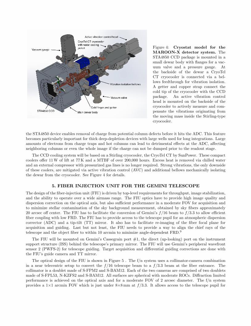
Figure 4: Cryostat model for theMAROON-X detector system. TheSTA4850 CCD package is mounted in asmall dewar body with flanges for a vac-uum valve and a pressure gauge. Atthe backside of the dewar a CryoTelCT cryocooler is connected via a bel-lows feedthrough for vibration isolation.A getter and copper strap connect thecold tip of the cryocooler with the CCDpackage. An active vibration controlhead is mounted on the backside of thecryocooler to actively measure and com-pensate the vibrations originating fromthe moving mass inside the Stirling-typecryocooler.
the STA4850 device enables removal of charge from potential column defects before it hits the ADC. This featurebecomes particularly important for thick deep-depletion devices with large wells used for long integrations. Largeamounts of electrons from charge traps and hot columns can lead to detrimental effects at the ADC, affectingneighboring columns or even the whole image if the charge can not be dumped prior to the readout stage.
The CCD cooling system will be based on a Stirling cryocooler, the CryoTel CT by SunPower. These compactcoolers offer 11 W of lift at 77 K and a MTBF of over 200,000 hours. Excess heat is removed via chilled waterand an external compressor with pressurized gas lines is no longer required. Strong vibrations, the only downsideof these coolers, are mitigated via active vibration control (AVC) and additional bellows mechanically isolatingthe dewar from the cryocooler. See Figure 4 for details.
5. FIBER INJECTION UNIT FOR THE GEMINI TELESCOPE
The design of the fiber-injection unit (FIU) is driven by top-level requirements for throughput, image stabilization,and the ability to operate over a wide airmass range. The FIU optics have to provide high image quality anddispersion correction on the optical axis, but also sufficient performance in a moderate FOV for acquisition andto minimize stellar contamination of the sky background measurement, obtained by sky fibers approximately20 arcsec off center. The FIU has to facilitate the conversion of Gemini’s f/16 beam to f/3.3 to allow efficientfiber coupling with low FRD. The FIU has to provide access to the telescope pupil for an atmospheric dispersioncorrector (ADC) and a tip-tilt (TT) mirror. It also has to facilitate re-imaging of the fiber focal plane foracquisition and guiding. Last but not least, the FIU needs to provide a way to align the chief rays of thetelescope and the object fiber to within 10 arcmin to minimize angle-dependent FRD.9
The FIU will be mounted on Gemini’s Cassegrain port #1, the direct (up-looking) port on the instrumentsupport structure (ISS) behind the telescope’s primary mirror. The FIU will use Gemini’s peripheral wavefrontsensor 2 (PWFS-2) for telescope guiding. Target acquisition and differential guiding corrections are done withthe FIU’s guide camera and TT mirror.
The optical design of the FIU is shown in Figure 5 . The f/n system uses a collimator-camera combinationin a near telecentric setup to convert the f/16 telescope beam to a f/3.3 beam at the fiber entrance. Thecollimator is a doublet made of S-FPM2 and S-BAM12. Each of the two cameras are comprised of two doubletsmade of S-FPL53, N-KZFS2 and S-BAM12. All surfaces are spherical with moderate ROCs. Diffraction limitedperformance is achieved on the optical axis and for a moderate FOV of 2 arcsec diameter. The f/n systemprovides a 1×1 arcmin FOV which is just under 8×8 mm at f/3.3. It allows access to the telescope pupil for

MAROON-X_FE-04 rev 0.1 Page 23 of 67
In Figure 6.1.2 and 6.1.3 we show the optomechanical elements (with the exception of the pupil viewer) on the breadboard, mounted to the ISS. We omit here cable routings and show the optical beam path for on-axis sources as well as field sources out to ±30 arcmin.
6.2 Opto-mechanical components We chose Thorlabs’ Polaris1 mirror mounts and posts for the three fold mirrors, as these have exceptional mechanical and thermal stability and provide dowel pins for precise mechanical referencing of the elements. These mounts are made of heat-treated stainless steel. Mirrors are mounted with a three-point contact, both radially and axially at their circumference. The clamping force is well constrained to minimize distortions on the mirror. We will consider potting the mirrors in the mount with a soft UV curable adhesive instead of mechanically clamping them to further minimize stress. The TT-mirror mount is a custom SS401 mount spider. A ring at 68% of the diameter and three pads at the edge of the mirror are used to pot the mirror into the mount which is then screwed onto the piezo TT stage.
1 https://www.thorlabs.com/newgrouppage9.cfm?objectgroup_id=11370
Figure 6.1.1: Optical design for the frontend unit. The f/16 focus of Gemini is reimaged onto a f/3.3 image plane, matching the acceptance cone of the fiber. A custom beamsplitter (BS) cube reflects 1% of the light, which is re-imaged with a second camera onto a sCMOS camera for active guiding. A tip-tilt mirror in the pupil plane facilitates the guiding with a precision of <0.1”. A classical ADC system provides on-axis compensation of the atmospheric dispersion to under 0.05” over 500-900nm down to air mass 2. Retractable optics (not shown here) are used to image the pupil of the telescope and the (back-illuminated) fiber to re-image the calibration fiber onto the science and sky fibers.
ISS mounting plane
Fold mirror 1 Gemini f/16 focus
Fold mirror 2 Collimator
Fold mirror 3
ADC
T/T mirror
BS cube
f/3.3 fiber focal plane
f/3.3 guide cam focal plane
Camera doublets
Camera doublets
Figure 5: Optical layout of the fiber injection unit (FIU) at the Gemini Telescope. The optical axisof the telescope is folded into a plane parallel to the primary mirror with the first fold mirror. The f/16 beamof Gemini is then collimated and passes through a classical ADC, which provides on-axis compensation of theatmospheric dispersion to under 50 mas over 500–900 nm down to air mass 2.5. A tip-tilt mirror in the pupilplane after the ADC facilitates differential guiding with a precision of ≤0.1 arcsec. A beamsplitter cube afterthe TT mirror reflects about 1% of the light towards a sCMOS camera for active guiding. The transmitted lightis re-imaged onto a f/3.3 image plane, matching the acceptance cone of the 100µm octagonal object fiber. Aretractable fold mirror between the ADC and fold mirror 3 (not shown here) is used to re-image the calibrationfiber (embedded in the fiber plate) onto the science and sky fibers for calibration.
placement of a tip-tilt mirror and an ADC prism pair set in close proximity in front of the tip-tilt mirror (seealso Figure 7).
The fibers at the f/3.3 focus are embedded in a fused silica plate. The 100µm octagonal object fiber isplaced in the center of the nominal optical axis and two sky fibers are placed at a distance of 20 arcsec (2.6 mm)to either side. Six additional fibers, three calibration fibers and three back-illuminated single-mode fibers, areplaced around the object fiber. Fresnel losses on the fibers are minimized by bonding a BBAR coated flat on topof the fiber plate. All fold mirrors and the tip-tilt mirror have high-efficiency dielectric coatings and all refractiveelements have a BBAR coating with an average reflectivity of R≤0.5%.
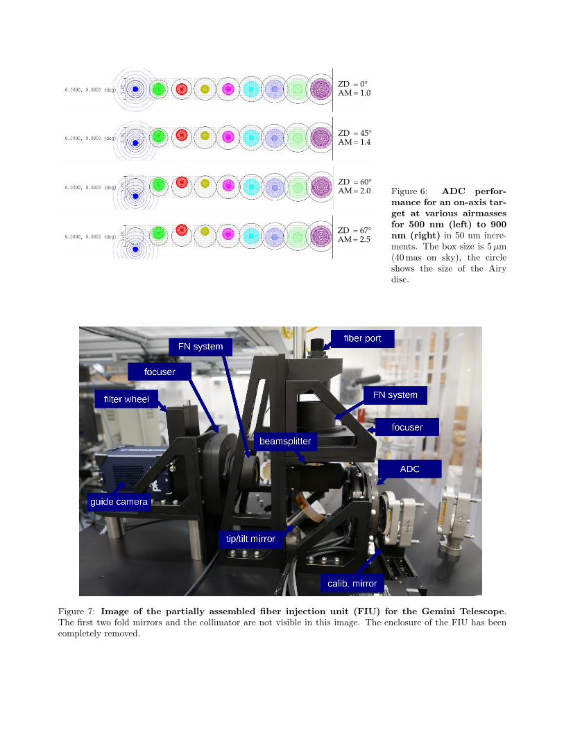
The ADC is of a classical design with two identical counter-rotating Risley prism pairs made of two carefullyselected glasses. The final design has a superb correction performance of ≤50 mas over 500–900 nm down to airmass 2.5, very forgiving tolerances for prism separation, and a low chief ray angle steering of under 7 arcmin(see Figure 6). The off-axis performance out to several 10 arcsec is still within our original requirements of ≤100mas for the maximum deviation over the full bandpass.
For the tip-tilt mirror we chose a stage from nPoint (model RXY6-210) with a closed-loop stroke of ±3 mrad(0.17◦), and hence a throw of ±6.3 arcsec (±4.4 arcsec) on sky in X and Y, respectively. It is thus desirableto offload offsets larger than about 2 arcsec to the telescope, particularly during object acquisition. Due to theweight of the mirror, the update frequency of the tip-tilt stage is limited to a few Hz. This is still fast enoughto correct for flexure inside the FIU, compensate for thermal drifts and residual beam steering of the ADC, andto steer the image of the calibration fiber to either the object or the sky fiber during calibration exposures.
MAROON-X_FE-04 rev 0.1 Page 14 of 67
Figure 5.3.1: ADC performance for an on-axis target at various airmasses for 500 nm (left) to 900 nm (right) in 50 nm increments. The box size is 5 µm (40 mas on sky), the circle shows the size of the Airy disc.
5.4 Calibration light injection Calibration light (flat, ThAr, etalon) needs to be injected into the science and the high-red sky fiber. Since at least one calibration light source, the etalon wavelength calibrator, is located at the spectrograph and not at the frontend, we decided to feed all calibration light sources via fibers from the spectrograph to the frontend. Since we need to make the fiber feed removable, it appeared easiest to incorporate them into the same fiber feed and into the fiber focal plane array. By inserting a mirror behind the tip-tilt (for practical reasons behind the ADC), light emitting from the calibration fiber(s) is imaged back onto the fiber focal plane array and can be steered with the tip-tilt mirror to either the science or the sky fiber. With the calibration mirror adjusted such that the calibration fibers are being imaged back on themselves, the required throw of the tip-tilt mirror is 8.4 arcmin (84% of the maximum throw). Zemax image simulations show that the double pass though the ADC (in its zero position) is inconsequential to the image quality. The same applies for the double-pass through the camera objective when he calibration fiber is imaged onto object fiber. There is some image blurring and chromatic aberrations for the high-res sky fiber position, which is of no concern since we do not rely on perfect wavelength calibrations for the sky fiber.
ZD = 45° AM = 1.4
ZD = 0° AM = 1.0
ZD = 60° AM = 2.0
ZD = 67° AM = 2.5
Figure 6: ADC perfor-mance for an on-axis tar-get at various airmassesfor 500 nm (left) to 900nm (right) in 50 nm incre-ments. The box size is 5µm(40 mas on sky), the circleshows the size of the Airydisc.
Figure 7: Image of the partially assembled fiber injection unit (FIU) for the Gemini Telescope.The first two fold mirrors and the collimator are not visible in this image. The enclosure of the FIU has beencompletely removed.
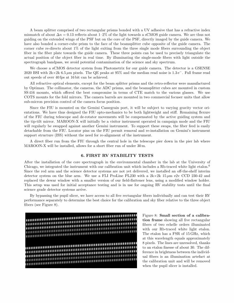
A beam splitter comprised of two rectangular prisms bonded with a UV adhesive that has a refractive indexmismatch of about ∆n = 0.13 reflects about 1–2% of the light towards a sCMOS guide camera. We are thus notguiding on the extended wings of the PSF but on the core of the PSF, directly imaged by the guide camera. Wehave also bonded a corner-cube prism to the face of the beamsplitter cube opposite of the guide camera. Thecorner cube re-directs about 1% of the light exiting from the three single mode fibers surrounding the objectfiber in the fiber plate towards the guide camera. These three points can be used to precisely triangulate theactual position of the object fiber in real time. By illuminating the single-mode fibers with light outside thespectrograph bandpass, we avoid potential contamination of the science and sky spectrum.
We choose a sCMOS detector system from Photometrix for our guide camera. The detector is a GSENSE2020 BSI with 2k×2k 6.5µm pixels. The QE peaks at 95% and the median read noise is 1.3 e−. Full frame readout speeds of over 40 fps at 16 bit can be achieved.
All refractive optical elements, except for the beam splitter prisms and the retro-reflector were manufacturedby Optimax. The collimator, the cameras, the ADC prisms, and the beamsplitter cubes are mounted in customSS 416 mounts, which offered the best compromise in terms of CTE match to the various glasses. We useCOTS mounts for the fold mirrors. The camera barrels are mounted in two commercial focuser units that allowsub-micron precision control of the camera focus position.
Since the FIU is mounted on the Gemini Cassegrain port, it will be subject to varying gravity vector ori-entations. We have thus designed the FIU opto-mechanics to be both lightweight and stiff. Remaining flexureof the FIU during telescope and de-rotator movements will be compensated by the active guiding system andthe tip-tilt mirror. MAROON-X will initially be a visitor instrument operated in campaign mode and the FIUwill regularly be swapped against another Gemini instrument. To support these swaps, the fiber feed is easilydetachable from the FIU. Locator pins on the FIU permit removal and re-installation on Gemini’s instrumentsupport structure (ISS) without the need for re-alignment of the instrument.
A direct fiber run from the FIU through the central hole in the telescope pier down in the pier lab whereMAROON-X will be installed, allows for a short fiber run of under 30 m.
6. FIRST RV STABILITY TESTS
After the installation of the core spectrograph in the environmental chamber in the lab at the University ofChicago, we integrated the instrument with our calibration unit which includes a Rb-traced white light etalon.6
Since the red arm and the science detector systems are not yet delivered, we installed an off-the-shelf interimdetector system on the blue arm. We use a FLI ProLine PL230 with a 2k×2k 15µm e2v CCD 230-42 andreplaced the dewar window with a smaller version of our field-flattener lens, using a modified window holder.This setup was used for initial acceptance testing and is in use for ongoing RV stability tests until the finalscience grade detector systems arrive.
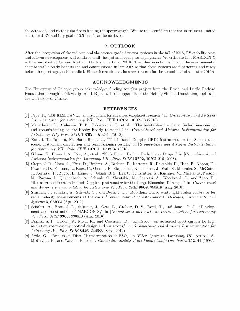
By bypassing the pupil slicer, we have access to all five rectangular fibers individually and can test their RVperformance separately to determine the best choice for the calibration and sky fiber relative to the three objectfibers (see Figure 8).
Figure 8: Small section of a calibra-tion frame showing all five rectangularfibers of two echelle orders illuminatedwith our Rb-traced white light etalon.The etalon has a FSR of 15 GHz, whichat this wavelength equals approximately8 pixels. The lines are unresolved, thanksto an etalon finesse of about 30. The dif-ference in brightness between the individ-ual fibers is an illumination artefact atthe calibration unit and will be removedwhen the pupil slicer is installed.

Figure 9: Difference in radial veloc-ity between one of the three sciencefibers and the calibration fiber forapproximately 4,000 etalon lines from 16orders of the blue arm on the interim2k×2k e2V detector. The timespan is 24hours. Data were taken with 10 second to5 minute cadence. No drift between thetwo fibers is apparent at the cm/s levelwith an RMS of 19 cm/s for the individ-ual exposures.
RV stability measurements at the sub-m s−1 level require a sophisticated software package. A first version ofthis package is operational and there are ongoing efforts to optimize it for eventual delivery with the instrument.Initial RV tests revealed a larger than expected instrumental response to external temperature variation insidethe environmental chamber with a clear correlation between absolute RV zero point and the temperature of thecamera and detector mount. Efforts are underway to isolate the responsible part and fix the issue.
However, inter-fiber drift, i.e. relative RV measurements between the science and the calibration fiber, mim-icking the actual RV observations during science observations, is not observed down to the cm s−1 level over a24 hr timespan. The rms of the individual RV measurements, taken at 10 s to 5 min cadence is only 19 cm s−1,see Figure 9. This is an encouraging result, given the limitations of this test. The spectral coverage of the 2k×2kinterim detector is much smaller than the final science grade detectors. Its temperature stability is severely lim-ited by its Peltier cooling system and the spectrograph was still settling towards its temperature setpoint. Lastbut not least, the pupil slicer and double scrambler was not used and we relied only on the scrambling power of
Table 1: MAROON-X main characteristics
Spectral resolution R = 80,000Acceptance angle FOV = 0.77” at the 8 m Gemini North TelescopeWavelength range 500 nm – 900 nm (in 56 orders)Number and reach of arms 2 (500–670 nm and 650–900 nm)Cross-disperser anamorphic VPH grismsBeam diameter 100 mm (at echelle grating), 33 mm (at cross-disperser)Main fiber 100µm octagonal (CeramOptec)Number and type of slicer 3x pupil slicerSlit forming fibers 5× 50×150µm rectangular (CeramOptec)Inter-order and inter-slice spacing ≥ 10 pixelAverage sampling 3.5 pixel per FWHMBlue detector Standard epi 30µm thick 4k×4k STA4850 CCD (15µm pixel size)Red detector Deep-depletion 100µm thick 4k×4k STA4850 CCD (15µm pixel size)Calibration Fabry-Perot etalon for simultaneous reference (fed by 2nd fiber)Environment for main optics Vacuum operation, 1 mK temperature stabilityEnvironment for camera optics Pressure sealed operation, 20 mK temperature stabilityLong-term instrument stability 0.7 m s−1 (requirement), 0.5 m s−1 (goal)Total efficiency 11% (requirement) to 15% (goal) at 700 nm (at median seeing)Observational efficiency S/N=100 at 750 nm for a V=16.5 late M dwarf in 30 min
the octagonal and rectangular fibers feeding the spectrograph. We are thus confident that the instrument-limitedend-to-end RV stability goal of 0.5 m s−1 can be achieved.
7. OUTLOOK
After the integration of the red arm and the science grade detector systems in the fall of 2018, RV stability testsand software development will continue until the system is ready for deployment. We estimate that MAROON-Xwill be installed at Gemini North in the first quarter of 2019. The fiber injection unit and the environmentalchamber will already be installed and commissioned in late 2018 so that these systems are functioning and readybefore the spectrograph is installed. First science observations are foreseen for the second half of semester 2019A.
ACKNOWLEDGMENTS
The University of Chicago group acknowledges funding for this project from the David and Lucile PackardFoundation through a fellowship to J.L.B., as well as support from the Heising-Simons Foundation, and fromthe University of Chicago.
REFERENCES
[1] Pepe, F., “ESPRESSO@VLT: an instrument for advanced exoplanet research,” in [Ground-based and AirborneInstrumentation for Astronomy VII ], Proc. SPIE 10702, 10702–33 (2018).
[2] Mahadevan, S., Anderson, T. B., Balderrama, E., et al., “The habitable-zone planet finder: engineeringand commissioning on the Hobby Eberly telescope,” in [Ground-based and Airborne Instrumentation forAstronomy VII ], Proc. SPIE 10702, 10702–40 (2018).
[3] Kotani, T., Tamura, M., Suto, H., et al., “The infrared Doppler (IRD) instrument for the Subaru tele-scope: instrument description and commissioning results,” in [Ground-based and Airborne Instrumentationfor Astronomy VII ], Proc. SPIE 10702, 10702–37 (2018).
[4] Gibson, S., Howard, A., Roy, A., et al., “Keck Planet Finder: Preliminary Design,” in [Ground-based andAirborne Instrumentation for Astronomy VII ], Proc. SPIE 10702, 10702–216 (2018).
[5] Crepp, J. R., Crass, J., King, D., Bechter, A., Bechter, E., Ketterer, R., Reynolds, R., Hinz, P., Kopon, D.,Cavalieri, D., Fantano, L., Koca, C., Onuma, E., Stapelfeldt, K., Thomes, J., Wall, S., Macenka, S., McGuire,J., Korniski, R., Zugby, L., Eisner, J., Gaudi, B. S., Hearty, F., Kratter, K., Kuchner, M., Micela, G., Nelson,M., Pagano, I., Quirrenbach, A., Schwab, C., Skrutskie, M., Sozzetti, A., Woodward, C., and Zhao, B.,“iLocater: a diffraction-limited Doppler spectrometer for the Large Binocular Telescope,” in [Ground-basedand Airborne Instrumentation for Astronomy VI ], Proc. SPIE 9908, 990819 (Aug. 2016).
[6] Sturmer, J., Seifahrt, A., Schwab, C., and Bean, J. L., “Rubidium-traced white-light etalon calibrator forradial velocity measurements at the cm s−1 level,” Journal of Astronomical Telescopes, Instruments, andSystems 3, 025003 (Apr. 2017).
[7] Seifahrt, A., Bean, J. L., Sturmer, J., Gers, L., Grobler, D. S., Reed, T., and Jones, D. J., “Develop-ment and construction of MAROON-X,” in [Ground-based and Airborne Instrumentation for AstronomyVI ], Proc. SPIE 9908, 990818 (Aug. 2016).
[8] Barnes, S. I., Gibson, S., Nield, K., and Cochrane, D., “KiwiSpec - an advanced spectrograph for highresolution spectroscopy: optical design and variations,” in [Ground-based and Airborne Instrumentation forAstronomy IV ], Proc. SPIE 8446, 844688 (Sept. 2012).
[9] Avila, G., “Results on Fiber Characterization at ESO,” in [Fiber Optics in Astronomy III ], Arribas, S.,Mediavilla, E., and Watson, F., eds., Astronomical Society of the Pacific Conference Series 152, 44 (1998).