Embed Size (px)
Citation preview


This instruction Manual may only be used by the buyer or user. It can not be distributed, published,
reproduced (partially or totally) or, in general, communicated to third parties without the express written
permission of the seller. Any breach of these rules may be subject to legal action.
Edition 2015.01
Mixers
1
Index
General ................................................................................................................................................................. 3 Identification ....................................................................................................................................................... 4 Spare parts and repairs. ................................................................................................................................... 4 Warranty .............................................................................................................................................................. 5 Safety advices ...................................................................................................................................................... 6
Basic safety rules: .................................................................................................................................... 7 Reception, storage and carriage ................................................................................................................... 9 Tank. Efforts and weights of mixer ............................................................................................................ 11 Mounting and installation ............................................................................................................................ 13
Mounting of shafts .............................................................................................................................. 14 Propellers Fixation. .............................................................................................................................. 17
Lubrication ........................................................................................................................................................ 22 Description: ........................................................................................................................................... 22 Position of the venting plug, oil input plug and oil drain plug. ............................................. 25
Start-up............................................................................................................................................................... 26 Motors ..................................................................................................................................................... 26 Variable-speed driver.......................................................................................................................... 28 Reducers ................................................................................................................................................. 29 Sealing systems .................................................................................................................................... 30 Thermosiphon ...................................................................................................................................... 31 Comissioning of mixer ........................................................................................................................ 32 Trouble-shooting ................................................................................................................................. 34
Maintenance .................................................................................................................................................... 35 Motor ...................................................................................................................................................... 35 Reducer .................................................................................................................................................. 35 Sealing systems .................................................................................................................................... 35 Thermosiphon: ..................................................................................................................................... 36 Shafts and turbines ............................................................................................................................. 36

Effective Mixing
2 Ed. 2015.01
Technical data sheets and spare parts list ............................................................................................... 37
VHS3 SERIES .......................................................................................................................................... 38 VHS3 Exploded view drawing ......................................................................................................... 39 VHD3 SERIES ......................................................................................................................................... 40 VHD3 Exploided view drawing ....................................................................................................... 41 VPP3 SERIES .......................................................................................................................................... 42 VPP3-VPH3 Exploded view drawing ............................................................................................. 43 VTA SERIES ............................................................................................................................................ 44 VTA4 Exploded view drawing ......................................................................................................... 45 VTS4-VTH4 SERIES ............................................................................................................................... 46 VTS4 Exploded view drawing .......................................................................................................... 47 VPT3 SERIES .......................................................................................................................................... 48 VPT3 Exploded view drawing ......................................................................................................... 49 VPS3 SERIES ........................................................................................................................................... 50 VPS3 Exploded view drawing.......................................................................................................... 51 VFR3 SERIES .......................................................................................................................................... 52 VFR3 Exploided View Drawing ....................................................................................................... 53 VFT2 SERIES........................................................................................................................................... 54 VFT2 Exploided view drawing ........................................................................................................ 55 L SERIES .................................................................................................................................................. 56 L Exploided view drawing ................................................................................................................ 57 HPS3 SERIES .......................................................................................................................................... 58 HPS3 Exploided view drawing ........................................................................................................ 59 Reducer section .................................................................................................................................... 60
Appendix ........................................................................................................................................................... 62 Tightening torque for screws .......................................................................................................... 62 Deflectors ............................................................................................................................................... 63
Declaration of conformity ............................................................................................................................ 64 ATEX Certificate ............................................................................................................................................... 65 ISO 9001 ............................................................................................................................................................ 66
Mixers
3
General
This technical manual contains the necessary instructions to install, start and
maintain of FLUIDMIX agitators and must be in hands of the personal in charge of these tasks.
It is imperative to read this manual before the mounting, disassembling or start-up of mixers, in order to avoid risks of accidents and damages to persons, to machines and installations.
In the repairs accomplished by the user himself / herself, use only original spare parts. Ask FluidMix for information about recommended spare parts and agitators section drawings.
It is advisable that the user keeps in his stockroom spare parts
recommended by FluidMix to be able to repair the machine as soon as possible.
Instructions must be followed carefully in case of 'Ex' mixers for explosive
atmospheres, preceded with symbol (these instructions only refer to Ex certificate mixers).
Effective Mixing
4 Ed. 2015.01
Identification
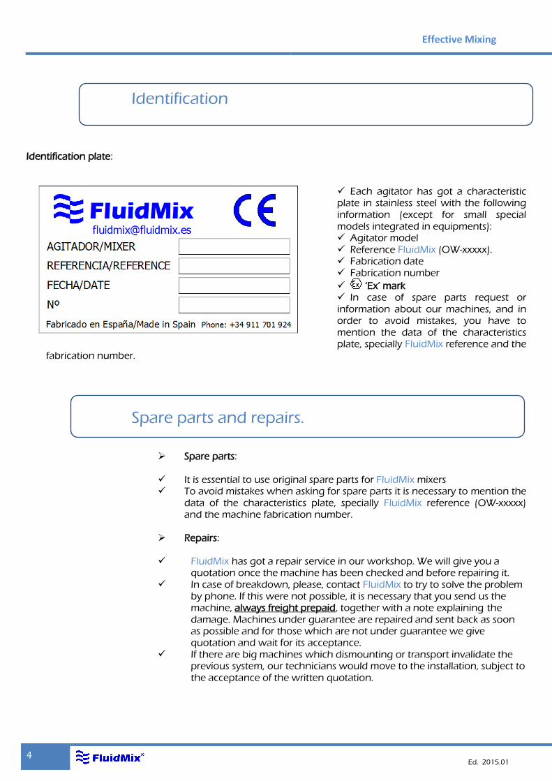
Identification plate:
Each agitator has got a characteristic plate in stainless steel with the following information (except for small special models integrated in equipments): Agitator model Reference FluidMix (OW-xxxxx). Fabrication date Fabrication number
‘Ex’ mark In case of spare parts request or information about our machines, and in order to avoid mistakes, you have to mention the data of the characteristics plate, specially FluidMix reference and the
fabrication number.
Spare parts and repairs.
Spare parts: It is essential to use original spare parts for FluidMix mixers To avoid mistakes when asking for spare parts it is necessary to mention the
data of the characteristics plate, specially FluidMix reference (OW-xxxxx) and the machine fabrication number.
Repairs: FluidMix has got a repair service in our workshop. We will give you a quotation once the machine has been checked and before repairing it. In case of breakdown, please, contact FluidMix to try to solve the problem by phone. If this were not possible, it is necessary that you send us the machine, always freight prepaid, together with a note explaining the damage. Machines under guarantee are repaired and sent back as soon as possible and for those which are not under guarantee we give quotation and wait for its acceptance. If there are big machines which dismounting or transport invalidate the previous system, our technicians would move to the installation, subject to the acceptance of the written quotation.

Mixers
5
Warranty
General: FluidMix guarantees its supply during 12 months after the delivery against
any defect of design, material or execution. This guarantee covers the substitution or repair by our charge and in our workshops of all faulty parts, being the buyer who must prove the mentioned defects. The substitution of one or several parts during the guarantee period does not extend this period.
FluidMix guarantees only covers the supplied machine(s); no reclamation is
admitted in case of breakdown for possible damages caused to the installation, to the product or to the quality of the production or for a decrease of it.
What the warranty do not cover: Costs resulting from dismounting, assembly and transport operations. Damages caused by an incorrect installation. Deterioration due to negligence. Damages caused by maintenance defects. Parts submitted to wear. Working after modifying the service or exploitation conditions. Deterioration resulting from storage in unsuitable conditions. Installation of spare parts or accessories different from FluidMix supply. Dismounting by the user of subsets such as mechanical seal cartridges,
reducers or motors invalidates the warranty. Wear in the shaft and propellers coating, rubber or plastic, because it is
considered as normal.

Effective Mixing
6 Ed. 2015.01
Safety advices
Safety symbols:
Safety messages and warning labels must be strictly adhered to in order to prevent accidents, as well as personal and property damage. The content of the section and embedded safety messages as well as warning labels in the individual risk levels is as follows:
Dangers:
Danger
Warning: The machine can be damaged.
Danger of electric current.
Risk of being bruised by moving parts.
Floating load. Danger of carriage.
Danger of falling-down parts.
Danger of falling.
Danger of poisoning.
Danger of explosive atmosphere.

Mixers
7
Imperatives:
Documentation. Consult it unconditionally!
Safety helmet.
Carrying strap.
Respiratory mask.
Lifting machines.
Basic safety rules:
Motor:
Comply with current electrical regulations.
The cable entry in the terminal box is made through a gland with characteristics appropriate to the installation. Once the connection is realized, mount terminal box cover with its corresponding gasket to prevent accidental contact with terminals.
Always connect the motor housing to a ground.
Motors must always operate with the fan cowl mounted in position; top grille must be free from obstructions to avoid excessive heating of the motor.
Reducer:
The agitator moving parts that are not inside of the tank should be covered with protections (grids, plates...) to prevent accidental contact. If due to the constructive characteristics of the equipment it’s impossible to mount a protection "avoid inserting hands or any object through the existing access"
Effective Mixing
8 Ed. 2015.01
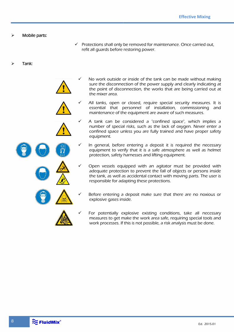
Mobile parts:
Protections shall only be removed for maintenance. Once carried out,
refit all guards before restoring power.
Tank:
No work outside or inside of the tank can be made without making sure the disconnection of the power supply and clearly indicating at the point of disconnection, the works that are being carried out at the mixer area.
All tanks, open or closed, require special security measures. It is essential that personnel of installation, commissioning and maintenance of the equipment are aware of such measures.
A tank can be considered a "confined space", which implies a number of special risks, such as the lack of oxygen. Never enter a confined space unless you are fully trained and have proper safety equipment.
In general, before entering a deposit it is required the necessary equipment to verify that it is a safe atmosphere as well as helmet protection, safety harnesses and lifting equipment.
Open vessels equipped with an agitator must be provided with adequate protection to prevent the fall of objects or persons inside the tank, as well as accidental contact with moving parts. The user is responsible for adapting these protections.
Before entering a deposit make sure that there are no noxious or explosive gases inside.
For potentially explosive existing conditions, take all necessary measures to get make the work area safe, requiring special tools and work processes. If this is not possible, a risk analysis must be done.

Mixers
9
Reception, storage and carriage
Reception: At reception of the material it is essential to check the following points:
Check the transport delivery note with the material, number of packages,
point of departure, etc... Specify in writing to the forwarder who delivers any fault observed in the
external of the packing such as strokes, breakings, humidity, rips, etc. opening immediately the package with faults and verifying its content. In case of receiving damaged goods, immediately inform the forwarder and FluidMix. In case of not doing like that, the eventual claims would be invalidated.
Storage:
Store the device in its packing, in a dry place protected against strokes and
dust, making sure previously that this packing is the suitable to support the environmental conditions in site. Any defective storage before and after the use under special environmental conditions (humidity, salinity, dust, vibrations, corrosion, etc.) restricts the conditions of the guarantee.
Before starting an agitator that has been mounted but has not worked or has been stopped for a long time, check out that there are no leaks of lubricant and the sealing of the motor since, keeping the agitator out of work, especially if it is outdoors, can lead to damage or hardening of the joints leading to leaks of lubricant, or water entry in the motor.
Shafts must be located on an even surface, with its corresponding protections or packings. Never use the agitator shaft as a lever or put weight on it.
In case of assemblies shaft-propeller(s) coated with plastic or rubber consider the previous precautions since just the rub with the floor can cause an exposed metallic point by which the corrosion will start; remind that coating is usually fragile and it is easy to deteriorate if there is not a very careful manipulation during storage and assembly.

Effective Mixing
10 Ed. 2015.01
Carriage:
The agitators, depending on the model, they are too heavy to be stored or installed manually. Use a suitable transport.
Take every precaution to lift the agitator. Always use the sling hooks when being transported by lifting system.
Larger gearboxes have threaded holes for screw according to DIN 580 lifting lugs or Eyebolts. The bolts are not included in the supply.
All the eyebolts must be tightened screwed. If you need auxiliary elements of lifting and transport
suitable with sufficient capacity, as flat rising (EN 1492-1) and lashing or stowing (EN 12195-2) webbing slings should be used.
The machines of transport and lifting should be ensured against slippage!
Maximize all precautions possible to lift the agitator. Always use tight slings if you move the agitator with a crane or other lifting system. Lifting or transport with several assistants, two cables or slings must withstand the weight.
Mixers
11
Tank. Efforts and weights of mixer
General recommendations:
Vessel which will incorporate the agitator must have the necessary design features to:
Avoid vibrations and oscillations of the vessel. Avoid damages in the tank in case that shaft or propeller could
loosen by accident or breakdown, even rotating at high speed, with the possibility of a leak of liquids, that may be toxic and/or corrosive.
FluidMix declines any responsibility for breakage of a deposit whose design must necessarily contemplate and take into account this possibility of accident.
The mixers are designed for mounting on a standard flanges, DIN, ANSI, usually in a vertical position at the top of the tank, although there are other models that are mounted on the side of the tank in a horizontal position.
For the fixation of the agitator in a concrete slab, we recommend, to do it with threaded rods.
For the correct fitting of the agitator on the tank, it is essential to keep in mind the following points:
The mixer shaft is designed to run in a vertical position. Check the horizontal alignment of the assembly drawing according
to two perpendicular directions, rectifying the position through the use of cleats, in order not to force the counter flange fixing. Mount and secure with the pair of torque corresponding to the measurement of the screw. See "pairs of tightening" in Appendix.
Agitator turbine or propeller should not be directly affected by current flow. If by design of the reservoir conditions the current flow has direct impact on the shaft or turbine, screens baffle must be prepared.

Effective Mixing
12 Ed. 2015.01
Efforts and weights of mixer
During the operation of the agitator, due to turbulence and another series
of complex hydrodynamic phenomena, each propeller produces a radial resulting perpendicular to the axis of the agitator and effort applied at its end. This effort multiplied by the length of the shaft gives the bending moment that should be considered for calculating the support structure. Due to the random nature of the forces and the rotation axis, the direction of these forces is constantly changing.
For this reason is essential to respect the distances of blades Assembly to the support of the shaker plate, since the machine has been calculated with this hypothesis; placing mobile support plate distances greater than expected can cause serious mechanical faults that in no case would cover the guarantee of FluidMix.
An axial flow Turbine generates an axial upward or downward effort depending on whether it is blowing or suctioning, respectively. If the axial stress is up will compensate in whole or in part the weight of the agitator, and may even exceed this weight. If the effort is falling will be added to the weight, what must be taken into account to calculate the corresponding
Agitator support structure has been designed to withstand the forces
mentioned above, and as a result, the forces are transmitted directly to the mounting bracket. The support structure must be rigid enough to withstand the weight of the agitator and agitator reactions resulting from the axial stress, the moment torque and bending moment.
On request, FluidMix will facilitate static and dynamic efforts produced by
the agitator so that manufacturer of the tank could calculate the appropriate structure support.
Mixers
13
Mounting and installation
General recommendations:
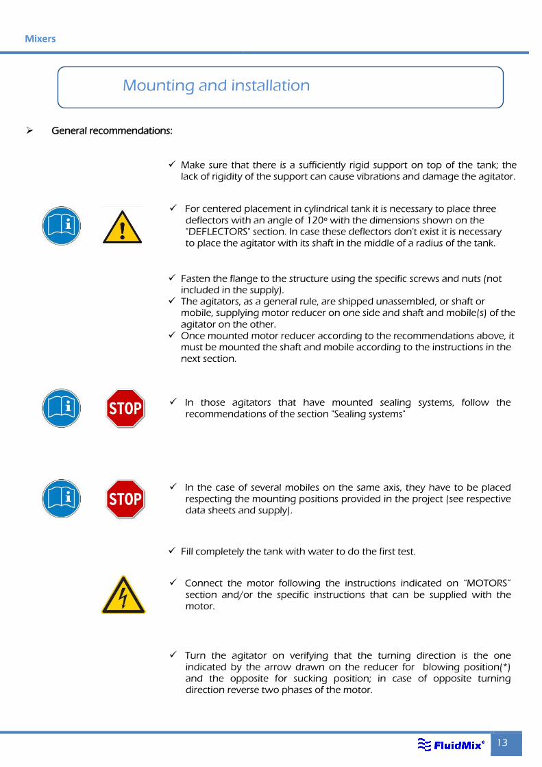
Make sure that there is a sufficiently rigid support on top of the tank; the
lack of rigidity of the support can cause vibrations and damage the agitator.
Fasten the flange to the structure using the specific screws and nuts (not
included in the supply). The agitators, as a general rule, are shipped unassembled, or shaft or
mobile, supplying motor reducer on one side and shaft and mobile(s) of the agitator on the other.
Once mounted motor reducer according to the recommendations above, it must be mounted the shaft and mobile according to the instructions in the next section.
Fill completely the tank with water to do the first test.
For centered placement in cylindrical tank it is necessary to place three deflectors with an angle of 120º with the dimensions shown on the "DEFLECTORS" section. In case these deflectors don't exist it is necessary to place the agitator with its shaft in the middle of a radius of the tank.
In those agitators that have mounted sealing systems, follow the recommendations of the section "Sealing systems"
In the case of several mobiles on the same axis, they have to be placed respecting the mounting positions provided in the project (see respective data sheets and supply).
Connect the motor following the instructions indicated on “MOTORS” section and/or the specific instructions that can be supplied with the motor.
Turn the agitator on verifying that the turning direction is the one indicated by the arrow drawn on the reducer for blowing position(*) and the opposite for sucking position; in case of opposite turning direction reverse two phases of the motor.
Effective Mixing
14 Ed. 2015.01
(*)To clarify the meaning of "sucking" or "blowing" propeller consult “PROPELLERS FIXATION” section.
Mounting of shafts
Description:
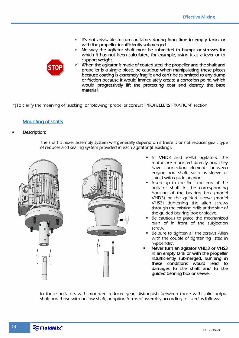
The shaft`s mixer assembly system will generally depend on if there is or not reducer gear, type of reducer and sealing system provided in each agitator (if existing).
In VHD3 and VHS3 agitators, the
motor are mounted directly and they have connecting elements between engine and shaft, such as sleeve or shield with guide bearing.
Insert up to the limit the end of the agitator shaft in the corresponding housing of the bearing box (model VHD3) or the guided sleeve (model VHS3) tightening the allen screws through the existing drills at the side of the guided bearing box or sleeve.
Be cautious to place the mechanized plan of in front of the subjection screw.
Be sure to tighten all the screws Allen with the couple of tightening listed in "Appendix".
Never turn an agitator VHD3 or VHS3 in an empty tank or with the propeller insufficiently submerged. Running in these conditions would lead to damages to the shaft and to the guided bearing box or sleeve.
In those agitators with mounted reducer gear, distinguish between those with solid output shaft and those with hollow shaft, adopting forms of assembly according to listed as follows:
It’s not advisable to turn agitators during long time in empty tanks or with the propeller insufficiently submerged.
No way the agitator shaft must be submitted to bumps or stresses for which it has not been calculated, for example, using it as a lever or to support weight.
When the agitator is made of coated steel the propeller and the shaft and propeller is a single piece, be cautious when manipulating these pieces because coating is extremely fragile and can't be submitted to any dump or friction because it would immediately create a corrosion point, which would progressively lift the protecting coat and destroy the base material.
Mixers
15
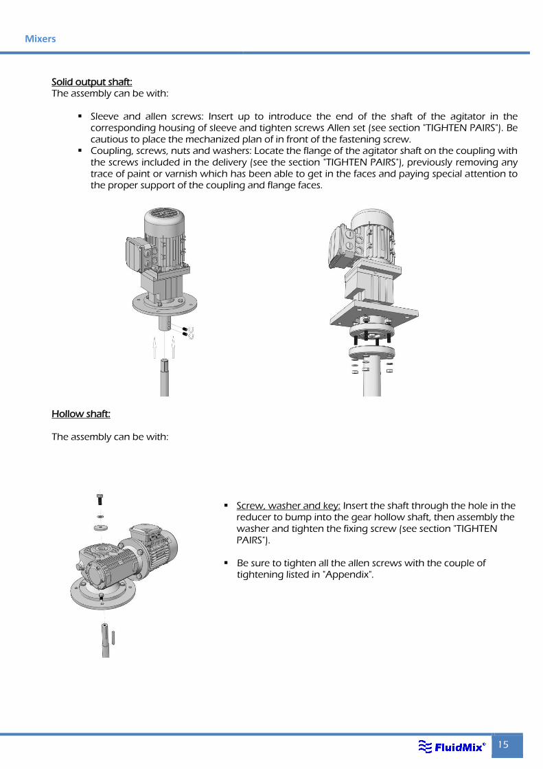
Solid output shaft: The assembly can be with:
Sleeve and allen screws: Insert up to introduce the end of the shaft of the agitator in the
corresponding housing of sleeve and tighten screws Allen set (see section "TIGHTEN PAIRS"). Be cautious to place the mechanized plan of in front of the fastening screw.
Coupling, screws, nuts and washers: Locate the flange of the agitator shaft on the coupling with the screws included in the delivery (see the section "TIGHTEN PAIRS"), previously removing any trace of paint or varnish which has been able to get in the faces and paying special attention to the proper support of the coupling and flange faces.
Hollow shaft:
The assembly can be with:
Screw, washer and key: Insert the shaft through the hole in the reducer to bump into the gear hollow shaft, then assembly the washer and tighten the fixing screw (see section "TIGHTEN PAIRS").
Be sure to tighten all the allen screws with the couple of tightening listed in "Appendix".
Effective Mixing
16 Ed. 2015.01
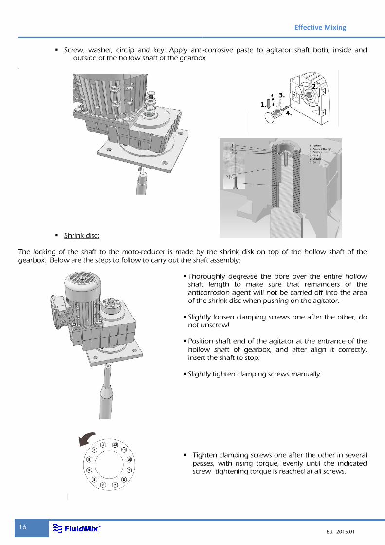
Screw, washer, circlip and key: Apply anti-corrosive paste to agitator shaft both, inside and outside of the hollow shaft of the gearbox
.
Shrink disc:
The locking of the shaft to the moto-reducer is made by the shrink disk on top of the hollow shaft of the gearbox. Below are the steps to follow to carry out the shaft assembly:
Thoroughly degrease the bore over the entire hollow shaft length to make sure that remainders of the anticorrosion agent will not be carried off into the area of the shrink disc when pushing on the agitator.
Slightly loosen clamping screws one after the other, do
not unscrew!
Position shaft end of the agitator at the entrance of the hollow shaft of gearbox, and after align it correctly, insert the shaft to stop.
Slightly tighten clamping screws manually.
Tighten clamping screws one after the other in several passes, with rising torque, evenly until the indicated screw−tightening torque is reached at all screws.
Mixers
17
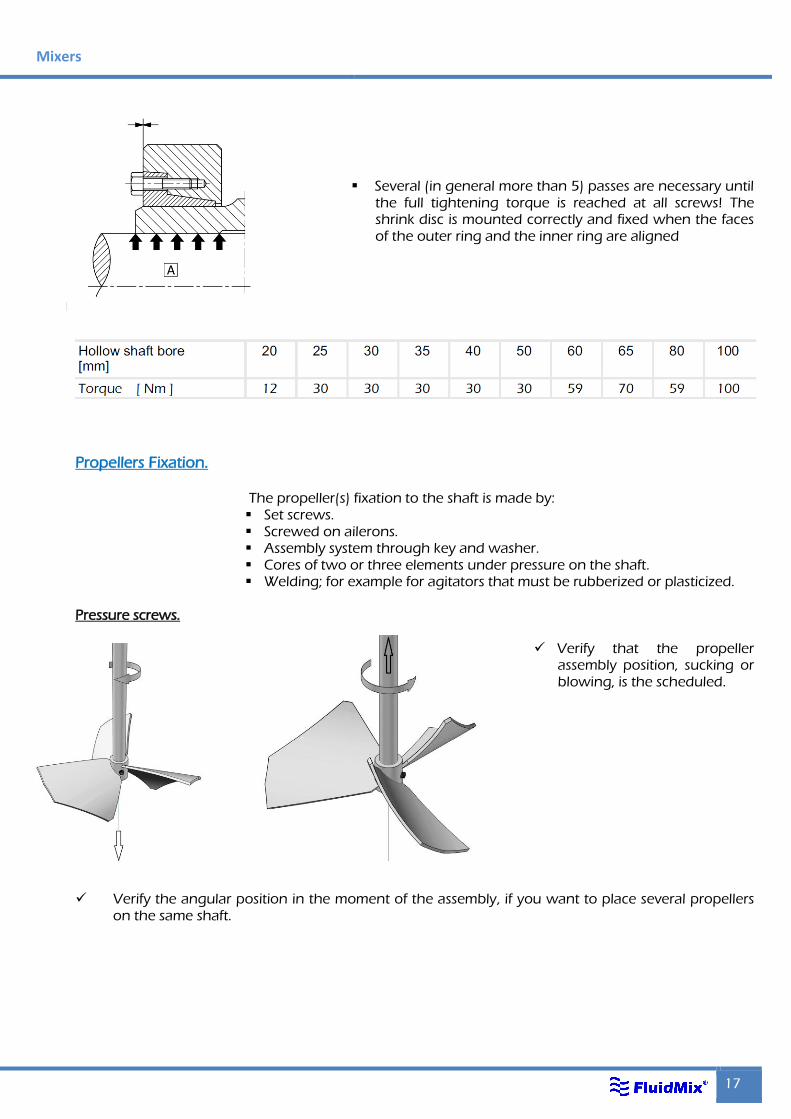
Several (in general more than 5) passes are necessary until
the full tightening torque is reached at all screws! The shrink disc is mounted correctly and fixed when the faces of the outer ring and the inner ring are aligned
Propellers Fixation.
The propeller(s) fixation to the shaft is made by: Set screws. Screwed on ailerons. Assembly system through key and washer. Cores of two or three elements under pressure on the shaft. Welding; for example for agitators that must be rubberized or plasticized.
Pressure screws.
Verify that the propeller
assembly position, sucking or blowing, is the scheduled.
Verify the angular position in the moment of the assembly, if you want to place several propellers
on the same shaft.
Effective Mixing
18 Ed. 2015.01
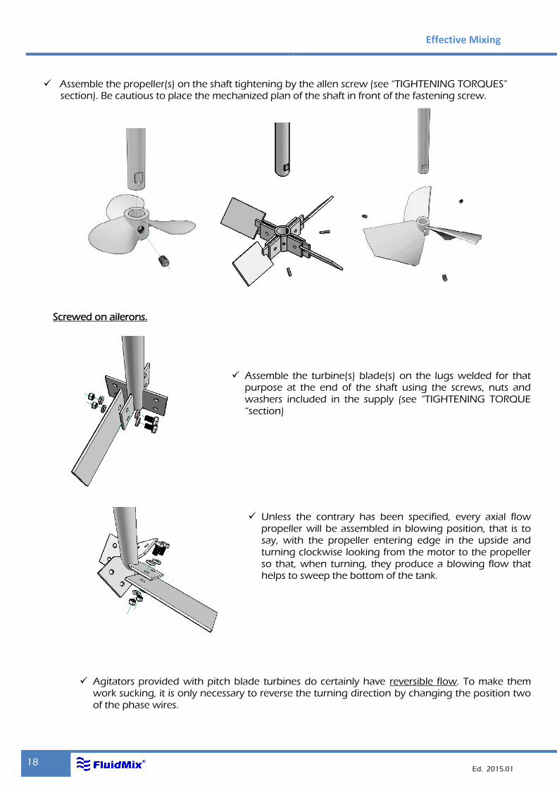
Assemble the propeller(s) on the shaft tightening by the allen screw (see “TIGHTENING TORQUES”
section). Be cautious to place the mechanized plan of the shaft in front of the fastening screw.
Screwed on ailerons.
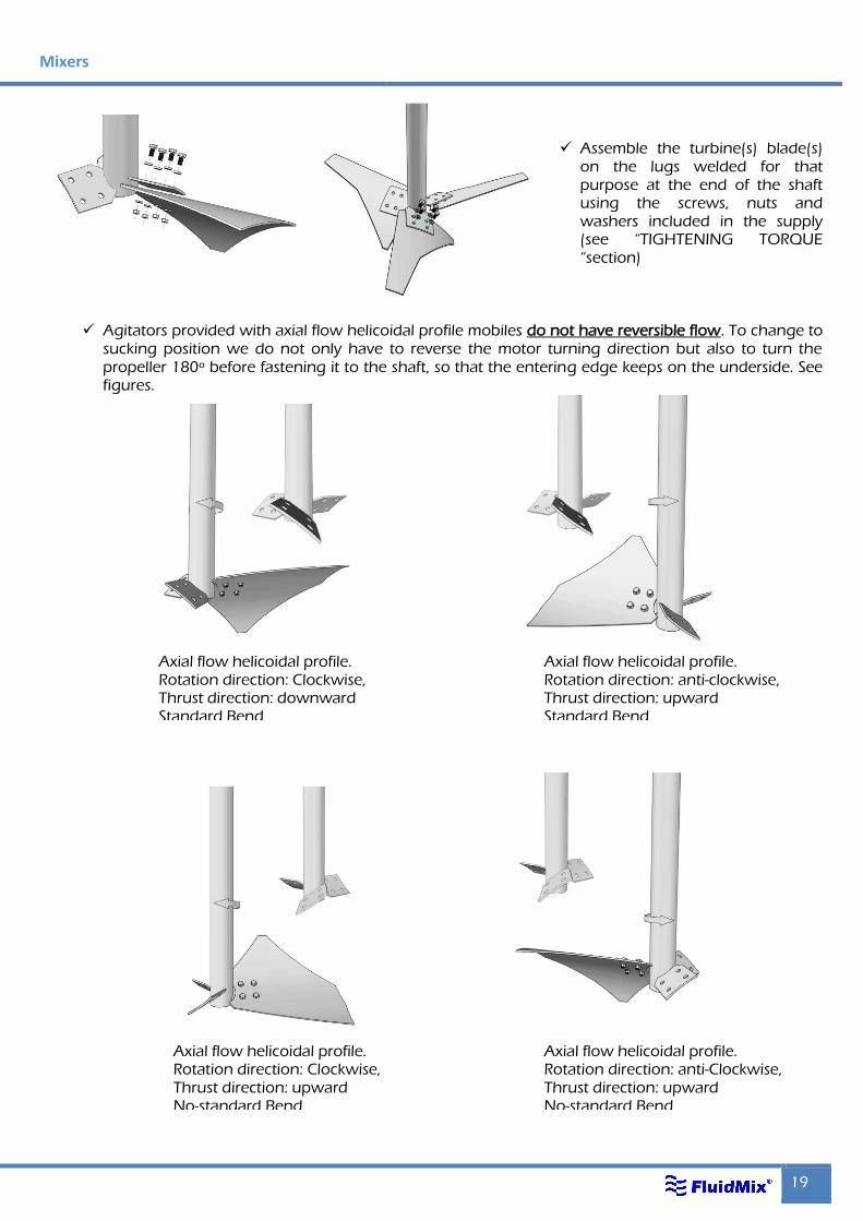
Assemble the turbine(s) blade(s) on the lugs welded for that purpose at the end of the shaft using the screws, nuts and washers included in the supply (see “TIGHTENING TORQUE “section)
Unless the contrary has been specified, every axial flow propeller will be assembled in blowing position, that is to say, with the propeller entering edge in the upside and turning clockwise looking from the motor to the propeller so that, when turning, they produce a blowing flow that helps to sweep the bottom of the tank.
Agitators provided with pitch blade turbines do certainly have reversible flow. To make them work sucking, it is only necessary to reverse the turning direction by changing the position two of the phase wires.
Mixers
19
Assemble the turbine(s) blade(s) on the lugs welded for that purpose at the end of the shaft using the screws, nuts and washers included in the supply (see “TIGHTENING TORQUE “section)
Agitators provided with axial flow helicoidal profile mobiles do not have reversible flow. To change to
sucking position we do not only have to reverse the motor turning direction but also to turn the propeller 180º before fastening it to the shaft, so that the entering edge keeps on the underside. See figures.
Axial flow helicoidal profile. Rotation direction: Clockwise, Thrust direction: downward Standard Bend
Axial flow helicoidal profile. Rotation direction: anti-Clockwise, Thrust direction: upward No-standard Bend
Axial flow helicoidal profile. Rotation direction: Clockwise, Thrust direction: downward Standard Bend
Axial flow helicoidal profile. Rotation direction: anti-clockwise, Thrust direction: upward Standard Bend
Axial flow helicoidal profile. Rotation direction: Clockwise, Thrust direction: upward No-standard Bend
Effective Mixing
20 Ed. 2015.01
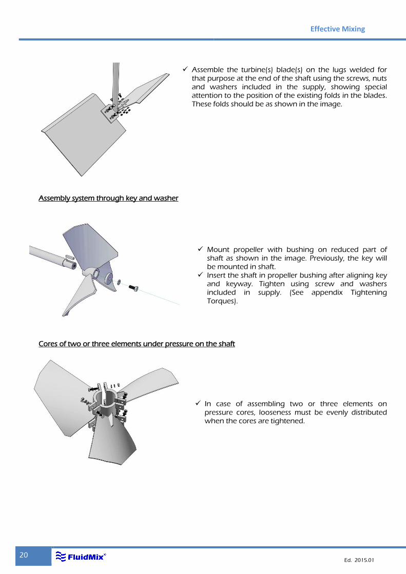
Assemble the turbine(s) blade(s) on the lugs welded for that purpose at the end of the shaft using the screws, nuts and washers included in the supply, showing special attention to the position of the existing folds in the blades. These folds should be as shown in the image.
Assembly system through key and washer
Mount propeller with bushing on reduced part of shaft as shown in the image. Previously, the key will be mounted in shaft.
Insert the shaft in propeller bushing after aligning key and keyway. Tighten using screw and washers included in supply. (See appendix Tightening Torques).
Cores of two or three elements under pressure on the shaft
In case of assembling two or three elements on
pressure cores, looseness must be evenly distributed when the cores are tightened.
Mixers
21
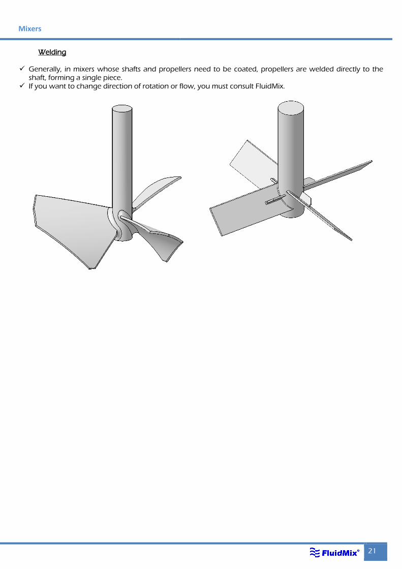
Welding
Generally, in mixers whose shafts and propellers need to be coated, propellers are welded directly to the shaft, forming a single piece.
If you want to change direction of rotation or flow, you must consult FluidMix.
Effective Mixing
22 Ed. 2015.01
Lubrication
Description:
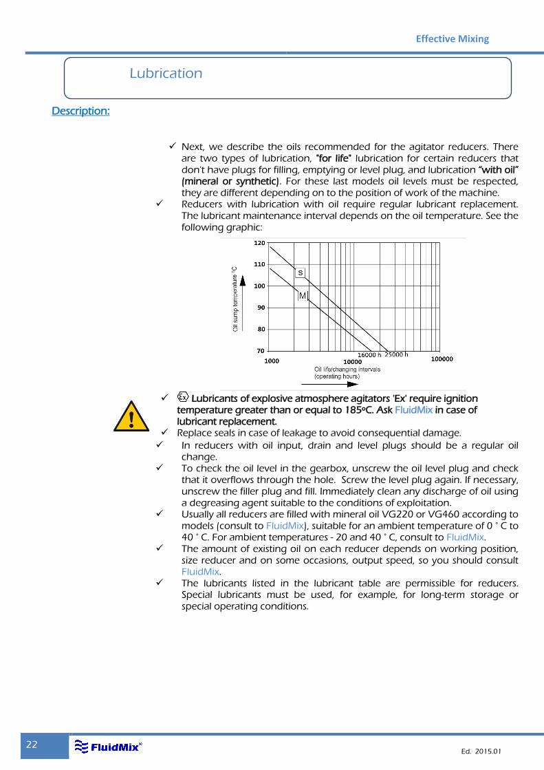
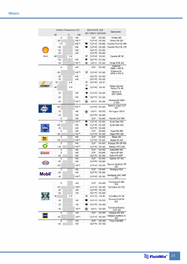
Next, we describe the oils recommended for the agitator reducers. There
are two types of lubrication, "for life" lubrication for certain reducers that don't have plugs for filling, emptying or level plug, and lubrication “with oil” (mineral or synthetic). For these last models oil levels must be respected, they are different depending on to the position of work of the machine.
Reducers with lubrication with oil require regular lubricant replacement. The lubricant maintenance interval depends on the oil temperature. See the following graphic:
Lubricants of explosive atmosphere agitators 'Ex' require ignition temperature greater than or equal to 185ºC. Ask FluidMix in case of lubricant replacement.
Replace seals in case of leakage to avoid consequential damage.
In reducers with oil input, drain and level plugs should be a regular oil change.
To check the oil level in the gearbox, unscrew the oil level plug and check that it overflows through the hole. Screw the level plug again. If necessary, unscrew the filler plug and fill. Immediately clean any discharge of oil using a degreasing agent suitable to the conditions of exploitation.
Usually all reducers are filled with mineral oil VG220 or VG460 according to models (consult to FluidMix), suitable for an ambient temperature of 0 ° C to 40 ° C. For ambient temperatures - 20 and 40 ° C, consult to FluidMix.
The amount of existing oil on each reducer depends on working position, size reducer and on some occasions, output speed, so you should consult FluidMix.
The lubricants listed in the lubricant table are permissible for reducers. Special lubricants must be used, for example, for long-term storage or special operating conditions.
Mixers
23
Effective Mixing
24 Ed. 2015.01
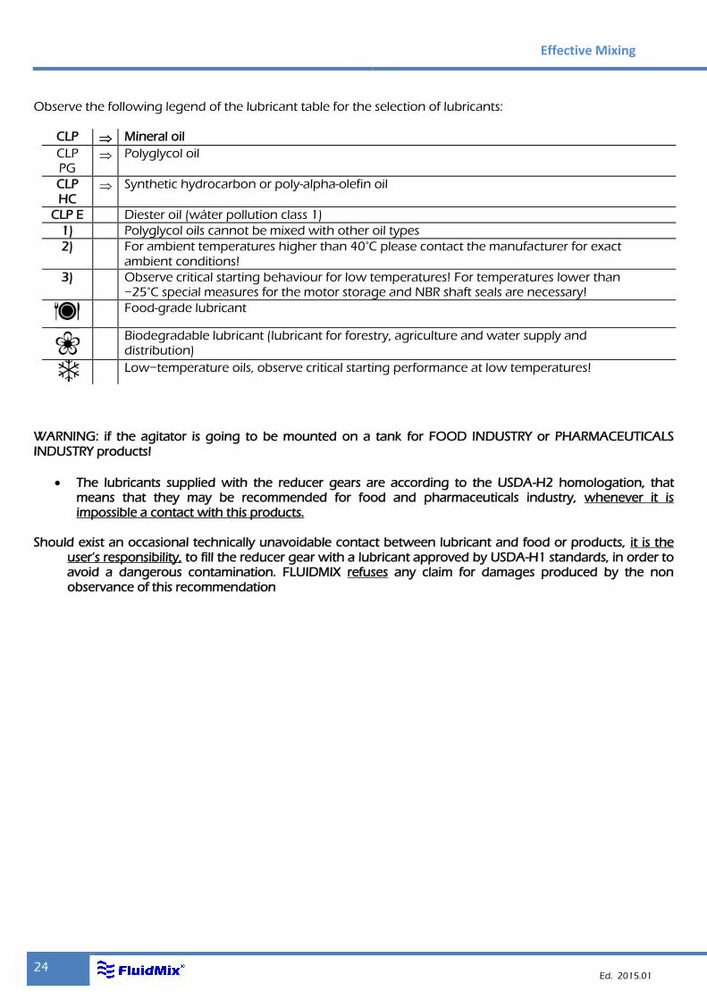
Observe the following legend of the lubricant table for the selection of lubricants:
CLP Mineral oil
CLP PG
Polyglycol oil
CLP HC
Synthetic hydrocarbon or poly-alpha-olefin oil
CLP E Diester oil (wáter pollution class 1)
1) Polyglycol oils cannot be mixed with other oil types
2) For ambient temperatures higher than 40°C please contact the manufacturer for exact ambient conditions!
3) Observe critical starting behaviour for low temperatures! For temperatures lower than −25°C special measures for the motor storage and NBR shaft seals are necessary!
Food-grade lubricant
Biodegradable lubricant (lubricant for forestry, agriculture and water supply and distribution)
Low−temperature oils, observe critical starting performance at low temperatures!
WARNING: if the agitator is going to be mounted on a tank for FOOD INDUSTRY or PHARMACEUTICALS INDUSTRY products!
The lubricants supplied with the reducer gears are according to the USDA-H2 homologation, that means that they may be recommended for food and pharmaceuticals industry, whenever it is impossible a contact with this products.
Should exist an occasional technically unavoidable contact between lubricant and food or products, it is the
user’s responsibility, to fill the reducer gear with a lubricant approved by USDA-H1 standards, in order to avoid a dangerous contamination. FLUIDMIX refuses any claim for damages produced by the non observance of this recommendation
Mixers
25
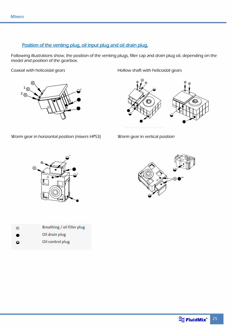
Position of the venting plug, oil input plug and oil drain plug.
Following illustrations show, the position of the venting plugs, filler cap and drain plug oil, depending on the model and position of the gearbox. Coaxial with helicoidal gears Hollow shaft with helicoidal gears
Worm gear in horizontal position (mixers HPS3)
Worm gear in vertical position
Effective Mixing
26 Ed. 2015.01
Start-up
Motors
Description:
All agitators are driven by a motor that can be: Electric Pneumatic Oleohydraulic
In this manual we will see electric motors because they are the most used in most applications. In case of pneumatic or oleohydraulic motors bear in mind the specific instructions of operation and maintenance supplied with the machine.
Connection and starting:
The electrical connection of the Motors must be performed by qualified
personnel. Take the necessary measures to prevent any breakdown.
It is necessary to carefully check all rating plate values in order to correctly carry out protection and motor connection.
Before making any connection check if the voltage and frequency available match that indicated on the nameplate of the motor and check that the motor turns freely by manually moving the fan blades.
Check that the section of the cable used is suitable to the voltage, power and distance from the engine up to the connection box.
Before commissioning, as well as after a period of prolonged unemployment or a storage it is necessary to check the insulation resistance!. To measure the insulation the main circuit wires must be disconnected.
During the measurement, and just after the same, terminals are subject partly to dangerous voltages, so it should not be touched.
If possible, the minimum insulation resistance of the winding on the casing of the machine must be measured for a temperature of the winding from 20 to 30° C for other temperatures apply different values for insulation resistance. Measurement must wait until the final resistance (approx. 1 minute) value is reached
Insulation resistance, at 25° C, must be greater than the reference value, i.e., 100 MΩ (measured at a voltage of 500 or 1,000 VDC).
The housing of the motor must be connected to Earth, and the windings must be discharged by landing to the housing immediately after each measurement, to avoid the risk of electric shock.
Mixers
27
If the resistance value is not reached, the winding is too humid and must be dried in the oven. The oven temperature should be 90 ° C for a period of 12 to 16 hours, and then 105 ° C for a period of 6 to 8 hours.
During heating, plugs the drain holes, if any, must be removed. Closing valves, if any, must be open. After heating, make sure to replace the plugs.
Even if there are drain plugs, it is recommended to remove the shields and covers cases of terminals for the drying process.
Normally, if the moisture is caused by sea water, the engine must be wound again.
Motors should always operate with the fan cowl mounted in his position; the grid of the top must be free from obstructions to avoid excessive heating of the motor.
Attention: FluidMix declines any responsibility on machines that have not been installed respecting the safety regulations in force. This circumstance also nullifies the warranty of the agitator.
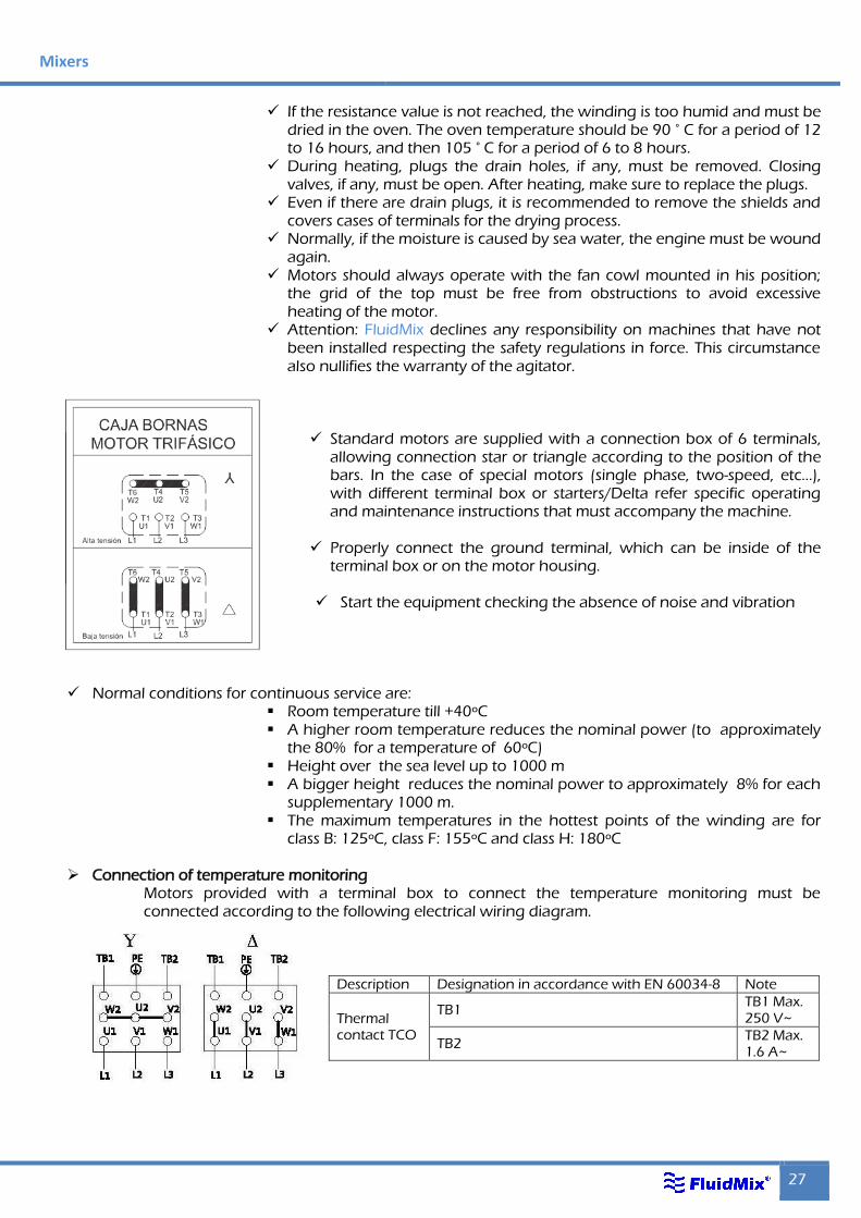
Standard motors are supplied with a connection box of 6 terminals, allowing connection star or triangle according to the position of the bars. In the case of special motors (single phase, two-speed, etc...), with different terminal box or starters/Delta refer specific operating and maintenance instructions that must accompany the machine.
Properly connect the ground terminal, which can be inside of the
terminal box or on the motor housing.
Start the equipment checking the absence of noise and vibration
Normal conditions for continuous service are:
Room temperature till +40ºC A higher room temperature reduces the nominal power (to approximately
the 80% for a temperature of 60ºC) Height over the sea level up to 1000 m A bigger height reduces the nominal power to approximately 8% for each
supplementary 1000 m. The maximum temperatures in the hottest points of the winding are for
class B: 125ºC, class F: 155ºC and class H: 180ºC
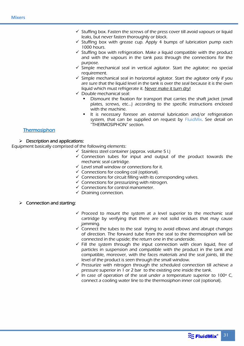
Connection of temperature monitoring Motors provided with a terminal box to connect the temperature monitoring must be connected according to the following electrical wiring diagram.
Description Designation in accordance with EN 60034-8 Note
Thermal contact TCO
TB1 TB1 Max. 250 V~
TB2 TB2 Max. 1.6 A~
Effective Mixing
28 Ed. 2015.01
Variable-speed driver
Description:
Variable-speed drive is used to control motor speed and torque by varying motor input frequency.
Aplications:
It is installed in those equipments where it is necessary to adjust the turning
speed with accuracy depending on the process. It can be placed near the agitator, in a control house or in an electric panel.
Assembly and starting:
Put the variable speed drive in a ventilated place without humidity or dust, exempt from metallic particles, vibrations, electromagnetic influences and far from fluorescent lamps.
Use the variator with a room temperature between –10ºC and +40ºC Always connect the variator to ground to avoid accidents and operation
problems. Verify that the voltage available coincides with the one necessary and it
does not have oscillations higher to the 10% of the nominal. In powers up to 1.5 kW. The feed voltage to the variator is usually single phase; the output voltage is always three-phase. Pay attention to the feeding connection of the variators, because if they are single phase and they are connected as three phases, damages are irreparable and under no circumstance they would be under FluidMix’s guarantee. Check in the manufacturer’s variator manual, included with the equipment, the connection schemes.
Connect the three phases of the motor to the converter terminal. The motor must be fed exclusively from the variator and any type of switch or commutator must be avoided in the wire that connects them.
Always connect the motor to ground through the converter terminal. Start the converter and verify the maximum and minimum range of speed
attainable (measured with a tachometer). This range must coincide with the one specified on the equipment offer. If it is not like that, immediately contact FluidMix because if the agitator turns at a higher or lower speed than the ones scheduled, that could lead to serious damages to it and to the installation.

Mixers
29
Reducers
Description:
Reducers for agitators can be:
Coaxial with helicoidal gears. Hollow shaft with helicoidal gears Right-angled with hollow shaft and helicoidal gears. Worm gear. “Tandem” type with parallel shafts for high torque and bending moment
Use:
It can be assembled on any type of agitator either vertical or horizontal
when the turning speed required for the shaft is different to the motor speed and constitutes one of the main pieces of these machines.
In most cases the reducer bearings are the ones which support the radial and axial stresses generated with the turning of the propeller(s) wether this is vertical or horizontal. That is why these reducers are always specially designed, not only to transmit a torque, but to be able to absorb axial stresses and bending moments.
When the agitator shaft is very long or the power to transmit is high a guided lantern is required after the reducer; in this case the bearings of that lantern are the ones that absorb the stresses and the reducer must be exclusively designed to transmit a twisting torque with your specific service factor.
The service factor of a reducer is the relation between the maximum transmissible power and the power absorbed by the mobile when it turns inside a liquid. Anyway the transmissible power for the reducer must be higher than the installed motor power.
The maximum normal temperature in the frame for reducers with cylindrical gears is 65/70 ºC and for worm gear reducers till 85 ºC. For higher temperatures consult FluidMix.
The maximum noise level must not exceed 85 dB for powers less than 37 kW.
Assembly and starting:
After having verified the points detailed on "MOTORS" section, check that the reducer is firmly anchored and that it has got the specific oil inside. See "LUBRICATION" section.
The type of lubrication recommended is shown on a label stuck to the reducer where it will be indicated "Full of oil" or "Life lubricated".
All reducers are supplied with the oil needed; nevertheless if for any reason the lubricant is sent apart that will be indicated on the reducer to fill it before starting.
In reducers lubricated by oil, verify that the level is suitable to the mounting position. In the lubricant input hole it is necessary to put a drilled plug, supplied with the equipment, to allow the degassing. In any work position the tankfull plug must be the one with the degassing hole.
Effective Mixing
30 Ed. 2015.01
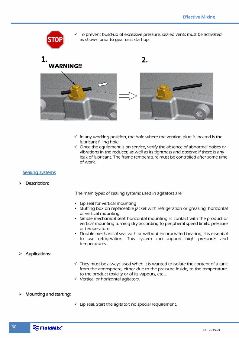
To prevent build-up of excessive pressure, sealed vents must be activated as shown prior to gear unit start up.
In any working position, the hole where the venting plug is located is the lubricant filling hole.
Once the equipment is on service, verify the absence of abnormal noises or vibrations in the reducer, as well as its tightness and observe if there is any leak of lubricant. The frame temperature must be controlled after some time of work.
Sealing systems
Description:
The main types of sealing systems used in agitators are: • Lip seal for vertical mounting • Stuffing box on replaceable jacket with refrigeration or greasing; horizontal
or vertical mounting. • Simple mechanical seal; horizontal mounting in contact with the product or
vertical mounting turning dry according to peripheral speed limits, pressure or temperature.
• Double mechanical seal with or without incorporated bearing; it is essential to use refrigeration. This system can support high pressures and temperatures.
Applications:
They must be always used when it is wanted to isolate the content of a tank
from the atmosphere, either due to the pressure inside, to the temperature, to the product toxicity or of its vapours, etc ...
Vertical or horizontal agitators.
Mounting and starting:
Lip seal. Start the agitator; no special requirement.
Mixers
31
Stuffing box. Fasten the screws of the press cover till avoid vapours or liquid leaks, but never fasten thoroughly or block.
Stuffing box with grease cup. Apply 4 bumps of lubrication pump each 1000 hours.
Stuffing box with refrigeration. Make a liquid compatible with the product and with the vapours in the tank pass through the connections for the purpose.
Simple mechanical seal in vertical agitator. Start the agitator; no special requirement.
Simple mechanical seal in horizontal agitator. Start the agitator only if you are sure that the liquid level in the tank is over the seal because it is the own liquid which must refrigerate it. Never make it turn dry!
Double mechanical seal: Dismount the fixation for transport that carries the shaft jacket (small
plates, screws, etc...) according to the specific instructions enclosed with the machine.
It is necessary foresee an external lubrication and/or refrigeration system, that can be supplied on request by FluidMix. See detail on “THERMOSIPHON” section.
Thermosiphon
Description and applications: Equipment basically comprised of the following elements:
Stainless steel container (approx. volume 5 l.) Connection tubes for input and output of the product towards the
mechanic seal cartridge. Level small window or connections for it. Connections for cooling coil (optional). Connections for circuit filling with its corresponding valves. Connections for pressurizing with nitrogen. Connections for control manometer. Draining connection.
Connection and starting:
Proceed to mount the system at a level superior to the mechanic seal
cartridge by verifying that there are not solid residues that may cause jamming.
Connect the tubes to the seal trying to avoid elbows and abrupt changes of direction. The forward tube from the seal to the thermosiphon will be connected in the upside; the return one in the underside.
Fill the system through the input connection with clean liquid, free of particles in suspension and compatible with the product in the tank and compatible, moreover, with the faces materials and the seal joints, till the level of the product is seen through the small window.
Pressurize with nitrogen through the scheduled connection till achieve a pressure superior in 1 or 2 bar to the existing one inside the tank.
In case of operation of the seal under a temperature superior to 100º C, connect a cooling water line to the thermosiphon inner coil (optional).
Effective Mixing
32 Ed. 2015.01
Comissioning of mixer
Each agitator model has been designed to obtain the maximum performance in your specific application. Be sure to mount the corresponding agitator according to technical specifications or drawings of overall dimensions.
If the conditions of the process such as density, viscosity, temperature, pressure... vary, it must be checked by FluidMix suitability of the agitator.
Verify the existence of no obstacles near the shaft and agitator turbine. A flow stream should never flow directly of on the shaft and the propeller
of the agitator. If necessary, deflection screens should be positioned. Do not make modifications to the agitator (change engine, speed of the
agitator, shaft length, diameter propellers...), without consulting FluidMix. Any modification may alter the functioning of the agitator, causing serious damage.
If any problems with the agitator, check the installation and read the
section "Problems, possible causes and solutions". If this still does not solve the problem, please contact FluidMix.
Before starting IS ESSENTIAL to check the following points:
The motor voltage which is written on the characteristics plate and which depends on the connection way must be the same that the one that we have in the grid.
The mechanic and thermal protections of the motor must be the needed ones.
The motor frame must always be connected to ground
Take apart the fan protection of the motor and turn the fan with your
hand to check that there are no hard points and that the propeller turns free. Assemble the fan protection verifying that the ventilator protection cover is free of obstructions.

Mixers
33
Check that the screws of the coupling that join the agitator head with the
shaft are appropriately tightened. In case of rigid coupling plates, before accomplishing the assembly it is necessary to remove any trace of paint, varnish or dirt from the faces which are going to be in contact.
Check the correct tightening of the screws that fasten the propeller.
Check that the speed reducer (if there is one) has a suitable oil level. To prevent build-up of excessive pressure, sealed vents must be activated
as shown prior to gear unit start up.
Effective Mixing
34 Ed. 2015.01
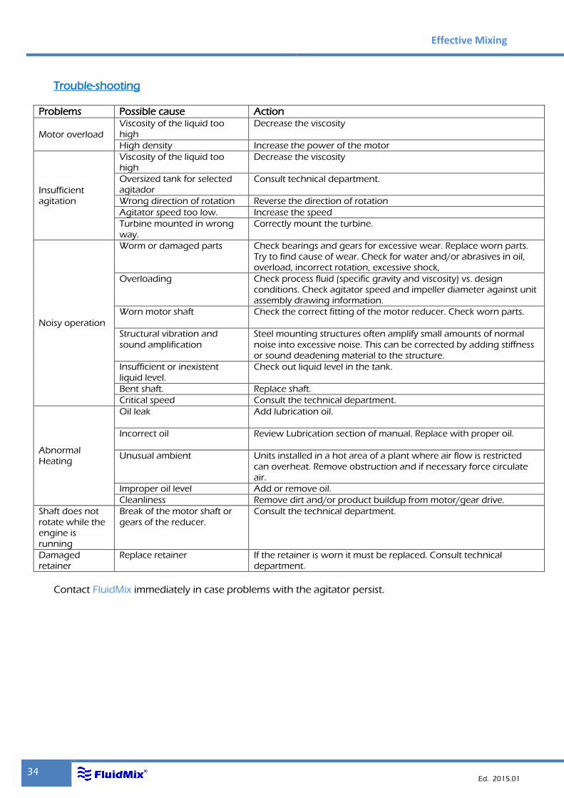
Trouble-shooting
Problems Possible cause Action
Motor overload
Viscosity of the liquid too high
Decrease the viscosity
High density Increase the power of the motor
Insufficient agitation
Viscosity of the liquid too high
Decrease the viscosity
Oversized tank for selected agitador
Consult technical department.
Wrong direction of rotation Reverse the direction of rotation
Agitator speed too low. Increase the speed
Turbine mounted in wrong way.
Correctly mount the turbine.
Noisy operation
Worm or damaged parts Check bearings and gears for excessive wear. Replace worn parts. Try to find cause of wear. Check for water and/or abrasives in oil, overload, incorrect rotation, excessive shock,
Overloading Check process fluid (specific gravity and viscosity) vs. design conditions. Check agitator speed and impeller diameter against unit assembly drawing information.
Worn motor shaft
Check the correct fitting of the motor reducer. Check worn parts.
Structural vibration and
sound amplification
Steel mounting structures often amplify small amounts of normal
noise into excessive noise. This can be corrected by adding stiffness or sound deadening material to the structure.
Insufficient or inexistent liquid level.
Check out liquid level in the tank.
Bent shaft. Replace shaft.
Critical speed Consult the technical department.
Abnormal Heating
Oil leak Add lubrication oil.
Incorrect oil
Review Lubrication section of manual. Replace with proper oil.
Unusual ambient Units installed in a hot area of a plant where air flow is restricted
can overheat. Remove obstruction and if necessary force circulate air.
Improper oil level Add or remove oil.
Cleanliness Remove dirt and/or product buildup from motor/gear drive.
Shaft does not
rotate while the engine is running
Break of the motor shaft or
gears of the reducer.
Consult the technical department.
Damaged retainer
Replace retainer If the retainer is worn it must be replaced. Consult technical department.
Contact FluidMix immediately in case problems with the agitator persist.
Mixers
35
Maintenance
Motor
Most motors with frame smaller than 160 or 200 (see the marks) have got "life greased" bearings.
Motors with bigger frame have got oiler(s). This system allows renewing the grease with the motor working, lubrication is recommended each 1000 hours in normal operation conditions. Consult "RECOMMENDED OILS AND GREASES" section.
Keep the ventilator cover free from strange objects to assure right refrigeration of the frame blades.
Motor and bearings are potentially ignition points in explosive atmospheres, that is why these parts need to be part of an exhaustive preventive maintenance plan. Before assembling spare parts and repair parts, it must be informed to FluidMix and then supervised by FluidMix.
Periodically and after long not-working period, motor must be cleaned to avoid dust accumulation and product agglomeration on mobile parts, such as shaft, and over its cover.
Reducer
No maintenance for "life lubricated" reducers. For reducers lubricated with oil, empty after the first 500 hours of work
letting oil flow out through the outlet hole till all the impurities produced by the tread have been dragged. After this period, change each 2500 hours of work or every 6 months, what happens first using mineral oils. Using synthetic oils (see tables on “LUBRICATION” section) the period to change is 12000 hours of work (always after the first 500 hours) or every 30 months, what happens first.
In case of apparition of vibrations or abnormal noises, substitute the faulty piece(s) asking FluidMix for a spare parts list.
Reducer is other important potentially ignition point in explosive atmospheres, that is why it must be part of an exhaustive preventive maintenance plan. Before assembling spare parts and repair parts, it must be informed to FluidMix and then supervised by FluidMix.
Periodically and after long not-working period, reducer must be cleaned to avoid dust accumulation and product agglomeration on mobile parts, such as shaft, and over its cover.
Sealing systems
Lip seal. No maintenance; substitute in case of wear. Stuffing box. Fasten softly the cover when there are leaks. Before the cover
reach the limit of its way because of the rings wear, add a new ring of suitable material and quality.
Simple mechanical seal. Substitute rub faces and joints when they are worn, ask FluidMix for a spare parts list.
Double mechanical seal. Dismount the whole cartridge to substitute the worn elements. This operation must be made in a specialized workshop, so it is convenient to send it to FluidMix for its repair and tests.
Effective Mixing
36 Ed. 2015.01
Thermosiphon:
Verify periodically the level and the circuit pressure in the thermosiphon. Its decrease can mean that there is a deterioration in the seal and that there are leaks in its faces.
Shafts and turbines
The emergence of abnormal vibrations is symptom of imbalance on the shaft or in the propeller or gaps in the guidance. Proceed to replace the defective(s) part(s) requesting a spare parts list to FluidMix.
Check regularly that the propeller or the connecting of this to the axis elements are clean and free of debris.
Make sure that shafts and propellers are free of snags with existing elements in the interior of the tank.
In general terms, preventive maintenance of every agitator component must include periodical cleaning that guarantees rust and dust absence in the hole agitator and specially in parts with metal-to-metal contact.
Re-painting processes must respect carefully original metal-to-metal contacts, as a guarantee of an effective ground connection of all parts to ensure the absence of electrostatic discharges which are a potentially risk of ignition in explosive atmospheres. In any event, this must be asked and advised by FluidMix. Total painting thickness can not be greater than 2mm.

Mixers
37
Technical data sheets and spare parts list
Next, you can find data sheets of standard range mixers of FluidMix. For other models, please contact with FluidMix.
If you need spare parts, consult lists of spare parts, or if you prefer, contact FluidMix, providing data from the nameplate.
For those special models, contact FluidMix to request the corresponding sheet.
Effective Mixing
38 Ed. 2015.01
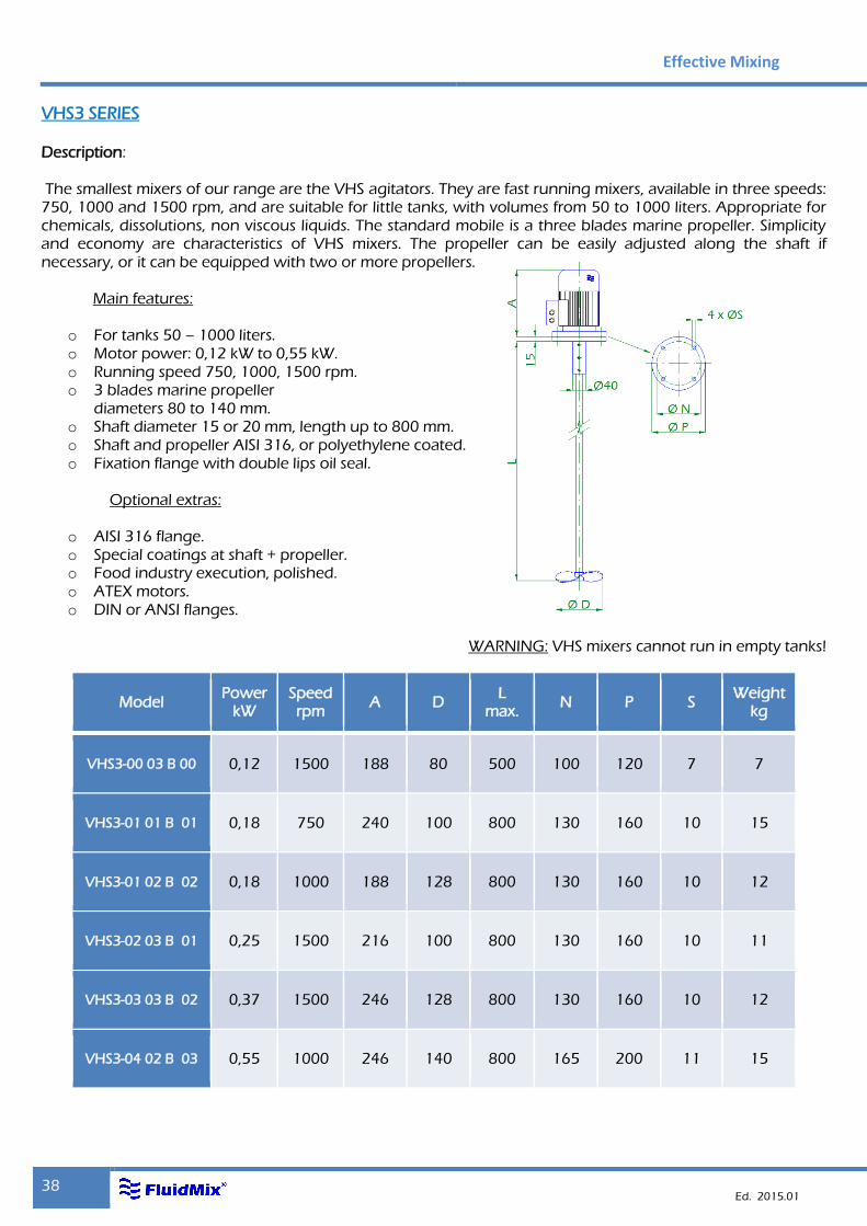
VHS3 SERIES
Description: The smallest mixers of our range are the VHS agitators. They are fast running mixers, available in three speeds: 750, 1000 and 1500 rpm, and are suitable for little tanks, with volumes from 50 to 1000 liters. Appropriate for chemicals, dissolutions, non viscous liquids. The standard mobile is a three blades marine propeller. Simplicity and economy are characteristics of VHS mixers. The propeller can be easily adjusted along the shaft if necessary, or it can be equipped with two or more propellers.
Main features:
o For tanks 50 – 1000 liters. o Motor power: 0,12 kW to 0,55 kW. o Running speed 750, 1000, 1500 rpm. o 3 blades marine propeller
diameters 80 to 140 mm. o Shaft diameter 15 or 20 mm, length up to 800 mm. o Shaft and propeller AISI 316, or polyethylene coated. o Fixation flange with double lips oil seal.
Optional extras:
o AISI 316 flange. o Special coatings at shaft + propeller. o Food industry execution, polished. o ATEX motors. o DIN or ANSI flanges.
WARNING: VHS mixers cannot run in empty tanks!
Model Power
kW Speed rpm
A D L
max. N P S
Weight kg
VHS3-00 03 B 00 0,12 1500 188 80 500 100 120 7 7
VHS3-01 01 B 01 0,18 750 240 100 800 130 160 10 15
VHS3-01 02 B 02 0,18 1000 188 128 800 130 160 10 12
VHS3-02 03 B 01 0,25 1500 216 100 800 130 160 10 11
VHS3-03 03 B 02 0,37 1500 246 128 800 130 160 10 12
VHS3-04 02 B 03 0,55 1000 246 140 800 165 200 11 15
Mixers
39
Model
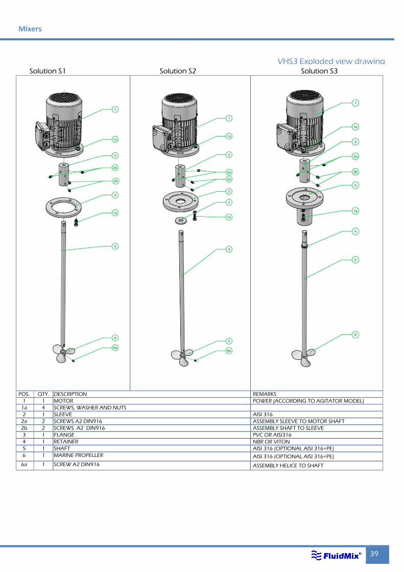
VHS3 Exploded view drawing
Solution S1 Solution S2 Solution S3
POS. QTY. DESCRIPTION REMARKS
1 1 MOTOR POWER (ACCORDING TO AGITATOR MODEL)
1a 4 SCREWS, WASHER AND NUTS
2 1 SLEEVE AISI 316
2a 2 SCREWS A2 DIN916 ASSEMBLY SLEEVE TO MOTOR SHAFT
2b 2 SCREWS A2 DIN916 ASSEMBLY SHAFT TO SLEEVE
3 1 FLANGE PVC OR AISI316
4 1 RETAINER NBR OR VITON
5 1 SHAFT AISI 316 (OPTIONAL AISI 316+PE)
6 1 MARINE PROPELLER AISI 316 (OPTIONAL AISI 316+PE)
6a 1 SCREW A2 DIN916 ASSEMBLY HELICE TO SHAFT
Effective Mixing
40 Ed. 2015.01
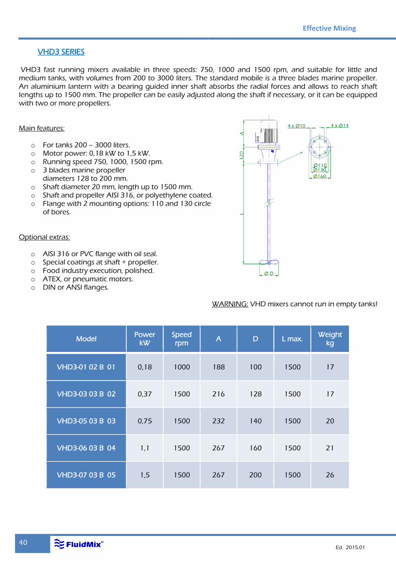
VHD3 SERIES
VHD3 fast running mixers available in three speeds: 750, 1000 and 1500 rpm, and suitable for little and medium tanks, with volumes from 200 to 3000 liters. The standard mobile is a three blades marine propeller. An aluminium lantern with a bearing guided inner shaft absorbs the radial forces and allows to reach shaft lengths up to 1500 mm. The propeller can be easily adjusted along the shaft if necessary, or it can be equipped with two or more propellers. Main features:
o For tanks 200 – 3000 liters. o Motor power: 0,18 kW to 1,5 kW. o Running speed 750, 1000, 1500 rpm. o 3 blades marine propeller
diameters 128 to 200 mm. o Shaft diameter 20 mm, length up to 1500 mm. o Shaft and propeller AISI 316, or polyethylene coated. o Flange with 2 mounting options: 110 and 130 circle
of bores. Optional extras:
o AISI 316 or PVC flange with oil seal. o Special coatings at shaft + propeller. o Food industry execution, polished. o ATEX, or pneumatic motors. o DIN or ANSI flanges.
WARNING: VHD mixers cannot run in empty tanks!
Model Power
kW Speed rpm
A D L max. Weight
kg
VHD3-01 02 B 01 0,18 1000 188 100 1500 17
VHD3-03 03 B 02 0,37 1500 216 128 1500 17
VHD3-05 03 B 03 0,75 1500 232 140 1500 20
VHD3-06 03 B 04 1,1 1500 267 160 1500 21
VHD3-07 03 B 05 1,5 1500 267 200 1500 26
Mixers
41
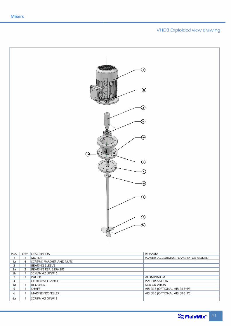
VHD3 Exploided view drawing
POS. QTY. DESCRIPTION REMARKS
1 1 MOTOR POWER (ACCORDING TO AGITATOR MODEL)
1a 4 SCREWS, WASHER AND NUTS
2 1 BEARING SLEEVE
2a 2 BEARING REF. 6256 2RS
2b 1 SCREW A2 DIN916
3 1 PALIER ALUMMINIUM
4 OPTIONAL FLANGE PVC OR AISI 316
4a 1 RETAINER NBR OR VITON
5 1 SHAFF AISI 316 (OPTIONAL AISI 316+PE)
6 1 MARINE PROPELLER AISI 316 (OPTIONAL AISI 316+PE)
6a 1 SCREW A2 DIN916
Effective Mixing
42 Ed. 2015.01
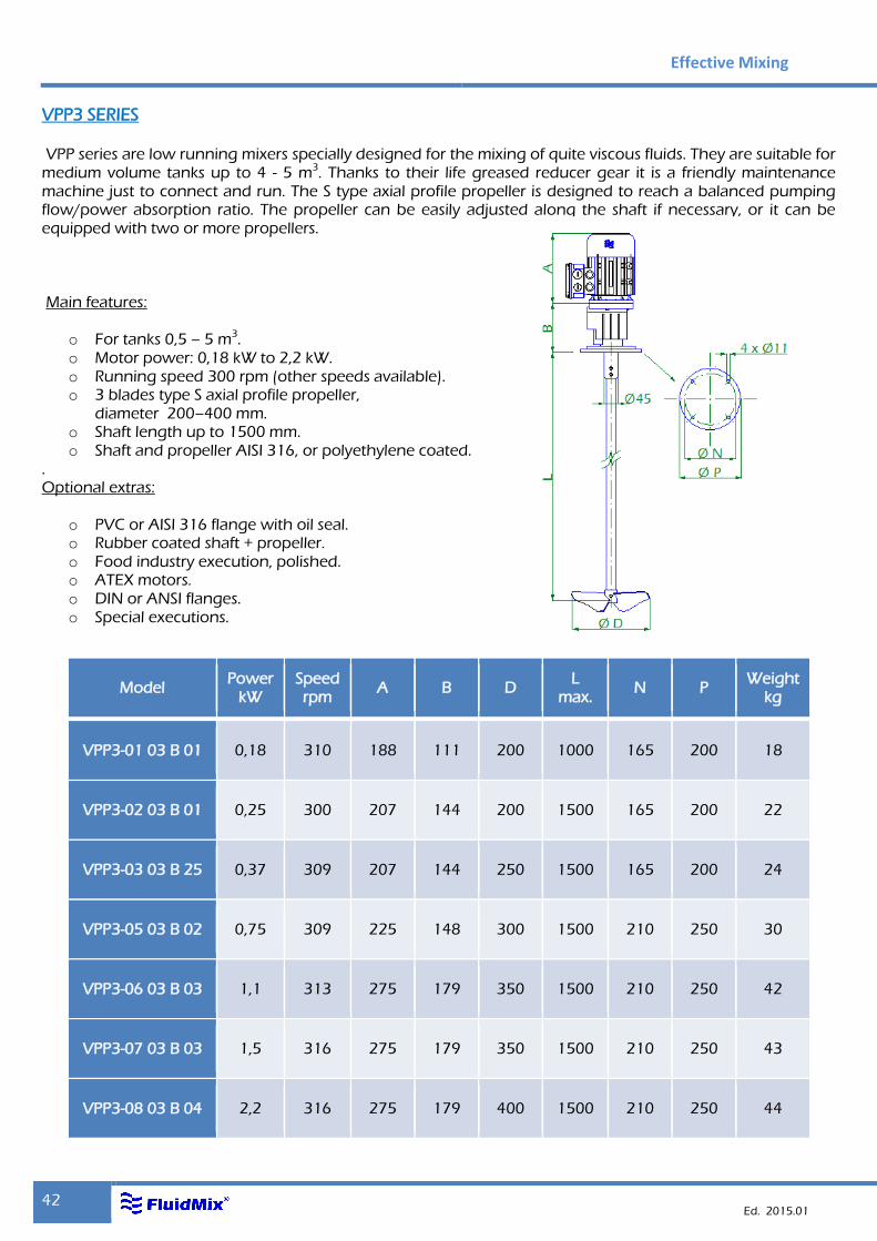
VPP3 SERIES
VPP series are low running mixers specially designed for the mixing of quite viscous fluids. They are suitable for medium volume tanks up to 4 - 5 m3. Thanks to their life greased reducer gear it is a friendly maintenance machine just to connect and run. The S type axial profile propeller is designed to reach a balanced pumping flow/power absorption ratio. The propeller can be easily adjusted along the shaft if necessary, or it can be equipped with two or more propellers. Main features:
o For tanks 0,5 – 5 m3. o Motor power: 0,18 kW to 2,2 kW. o Running speed 300 rpm (other speeds available). o 3 blades type S axial profile propeller,
diameter 200–400 mm. o Shaft length up to 1500 mm. o Shaft and propeller AISI 316, or polyethylene coated.
. Optional extras:
o PVC or AISI 316 flange with oil seal. o Rubber coated shaft + propeller. o Food industry execution, polished. o ATEX motors. o DIN or ANSI flanges. o Special executions.
Model Power
kW Speed rpm
A B D L
max. N P
Weight kg
VPP3-01 03 B 01 0,18 310 188 111 200 1000 165 200 18
VPP3-02 03 B 01 0,25 300 207 144 200 1500 165 200 22
VPP3-03 03 B 25 0,37 309 207 144 250 1500 165 200 24
VPP3-05 03 B 02 0,75 309 225 148 300 1500 210 250 30
VPP3-06 03 B 03 1,1 313 275 179 350 1500 210 250 42
VPP3-07 03 B 03 1,5 316 275 179 350 1500 210 250 43
VPP3-08 03 B 04 2,2 316 275 179 400 1500 210 250 44
Mixers
43
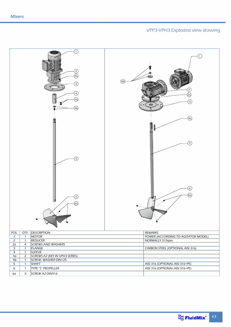
VPP3-VPH3 Exploded view drawing
POS. QTY. DESCRIPTION REMARKS
1 1 MOTOR POWER (ACCORDING TO AGITATOR MODEL)
2 1 REDUCER NORMALLY 315rpm
2a 4 SCREWS AND WASHERS
3 1 FLANGE CARBON STEEL (OPTIONAL AISI 316)
4 1 SLEEVE
4a 2 SCREWS A2 (KEY IN VPH3 SERIES)
4b 1 SCREW, WASHER DIN125
5 1 SHAFT AISI 316 (OPTIONAL AISI 316+PE)
6 1 TYPE “S” PROPELLER AISI 316 (OPTIONAL AISI 316+PE)
6a 3 SCREW A2 DIN916
Effective Mixing
44 Ed. 2015.01
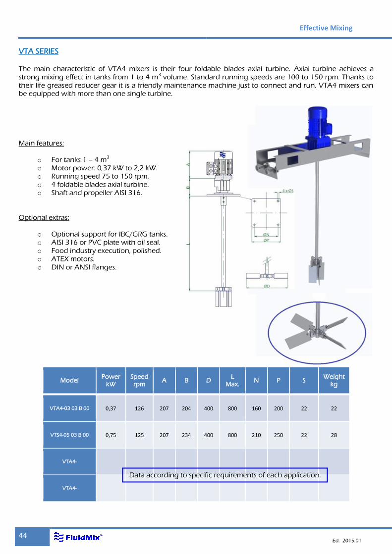
VTA SERIES
The main characteristic of VTA4 mixers is their four foldable blades axial turbine. Axial turbine achieves a strong mixing effect in tanks from 1 to 4 m3 volume. Standard running speeds are 100 to 150 rpm. Thanks to their life greased reducer gear it is a friendly maintenance machine just to connect and run. VTA4 mixers can be equipped with more than one single turbine. Main features:
o For tanks 1 – 4 m3 o Motor power: 0,37 kW to 2,2 kW. o Running speed 75 to 150 rpm. o 4 foldable blades axial turbine. o Shaft and propeller AISI 316.
Optional extras:
o Optional support for IBC/GRG tanks. o AISI 316 or PVC plate with oil seal. o Food industry execution, polished. o ATEX motors. o DIN or ANSI flanges.
Model Power
kW Speed rpm
A B D L
Max. N P S
Weight kg
VTA4-03 03 B 00 0,37 126 207 204 400 800 160 200 22 22
VTS4-05 03 B 00 0,75 125 207 234 400 800 210 250 22 28
VTA4-
VTA4-
Data according to specific requirements of each application.
Mixers
45
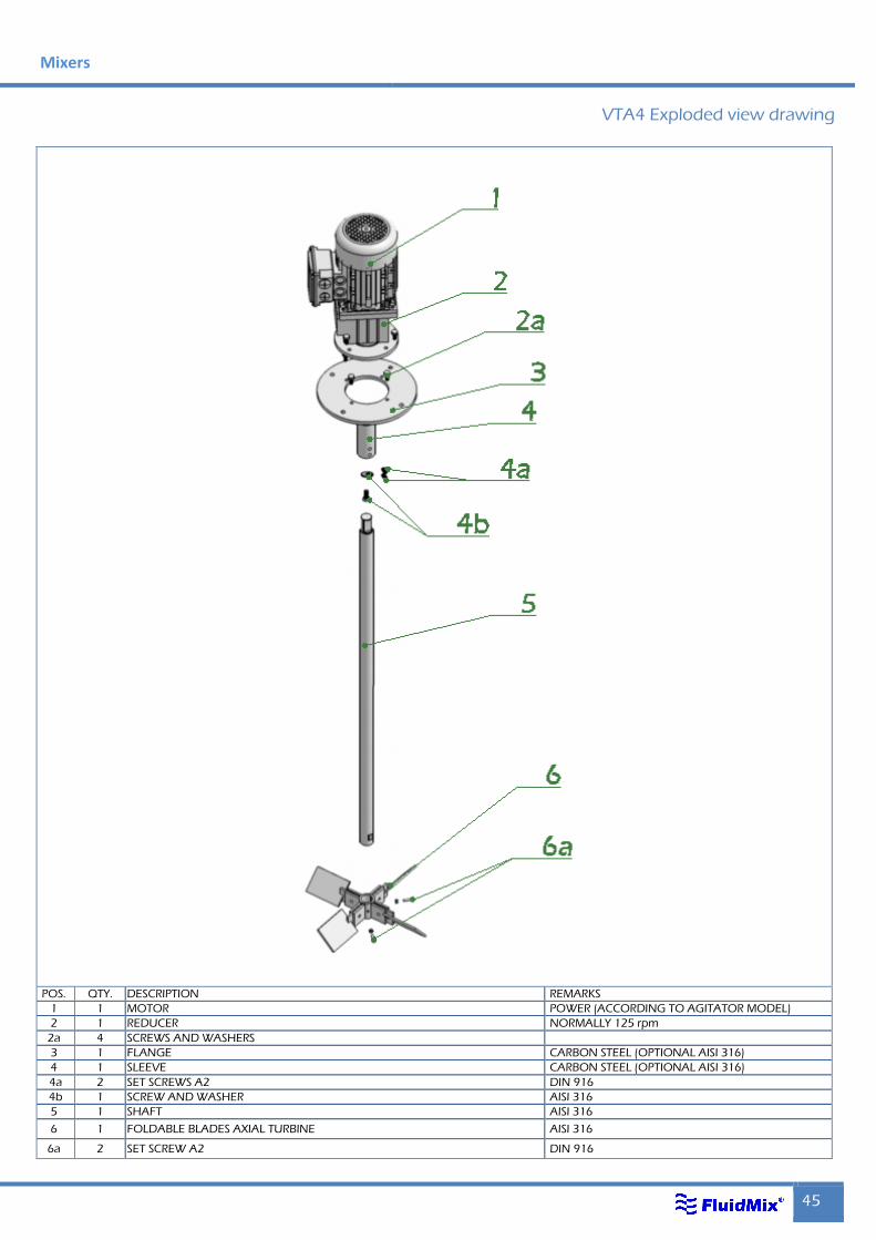
VTA4 Exploded view drawing
POS. QTY. DESCRIPTION REMARKS
1 1 MOTOR POWER (ACCORDING TO AGITATOR MODEL)
2 1 REDUCER NORMALLY 125 rpm
2a 4 SCREWS AND WASHERS
3 1 FLANGE CARBON STEEL (OPTIONAL AISI 316)
4 1 SLEEVE CARBON STEEL (OPTIONAL AISI 316)
4a 2 SET SCREWS A2 DIN 916
4b 1 SCREW AND WASHER AISI 316
5 1 SHAFT AISI 316
6 1 FOLDABLE BLADES AXIAL TURBINE AISI 316
6a 2 SET SCREW A2 DIN 916
Effective Mixing
46 Ed. 2015.01
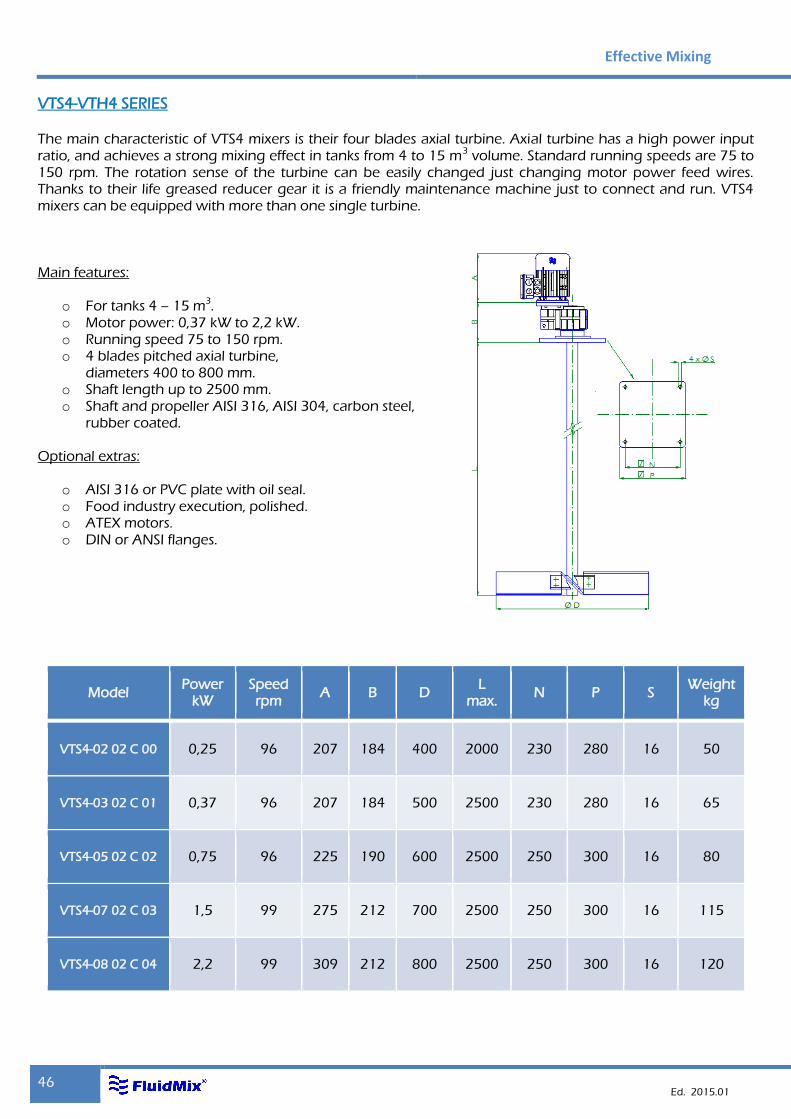
VTS4-VTH4 SERIES
The main characteristic of VTS4 mixers is their four blades axial turbine. Axial turbine has a high power input ratio, and achieves a strong mixing effect in tanks from 4 to 15 m3 volume. Standard running speeds are 75 to 150 rpm. The rotation sense of the turbine can be easily changed just changing motor power feed wires. Thanks to their life greased reducer gear it is a friendly maintenance machine just to connect and run. VTS4 mixers can be equipped with more than one single turbine. Main features:
o For tanks 4 – 15 m3. o Motor power: 0,37 kW to 2,2 kW. o Running speed 75 to 150 rpm. o 4 blades pitched axial turbine,
diameters 400 to 800 mm. o Shaft length up to 2500 mm. o Shaft and propeller AISI 316, AISI 304, carbon steel,
rubber coated. Optional extras:
o AISI 316 or PVC plate with oil seal. o Food industry execution, polished. o ATEX motors. o DIN or ANSI flanges.
Model Power
kW Speed rpm
A B D L
max. N P S
Weight kg
VTS4-02 02 C 00 0,25 96 207 184 400 2000 230 280 16 50
VTS4-03 02 C 01 0,37 96 207 184 500 2500 230 280 16 65
VTS4-05 02 C 02 0,75 96 225 190 600 2500 250 300 16 80
VTS4-07 02 C 03 1,5 99 275 212 700 2500 250 300 16 115
VTS4-08 02 C 04 2,2 99 309 212 800 2500 250 300 16 120
Mixers
47
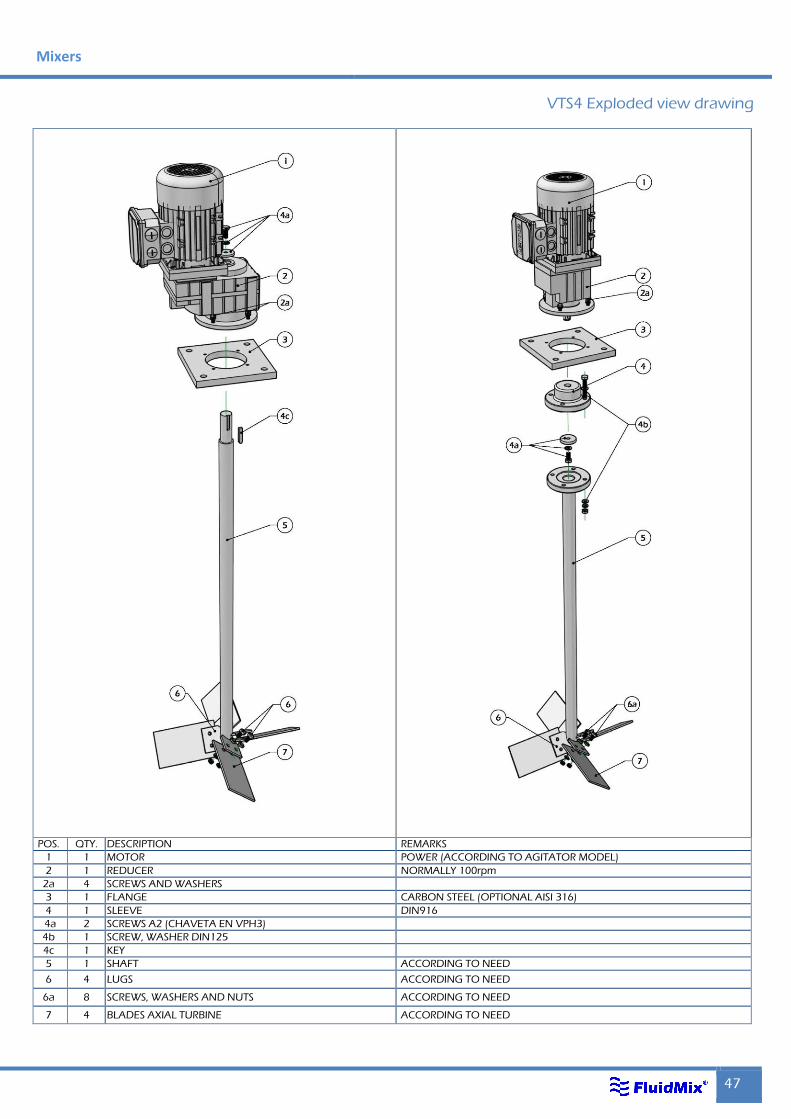
VTS4 Exploded view drawing
POS. QTY. DESCRIPTION REMARKS
1 1 MOTOR POWER (ACCORDING TO AGITATOR MODEL)
2 1 REDUCER NORMALLY 100rpm
2a 4 SCREWS AND WASHERS
3 1 FLANGE CARBON STEEL (OPTIONAL AISI 316)
4 1 SLEEVE DIN916
4a 2 SCREWS A2 (CHAVETA EN VPH3)
4b 1 SCREW, WASHER DIN125
4c 1 KEY
5 1 SHAFT ACCORDING TO NEED
6 4 LUGS ACCORDING TO NEED
6a 8 SCREWS, WASHERS AND NUTS ACCORDING TO NEED
7 4 BLADES AXIAL TURBINE ACCORDING TO NEED
Effective Mixing
48 Ed. 2015.01
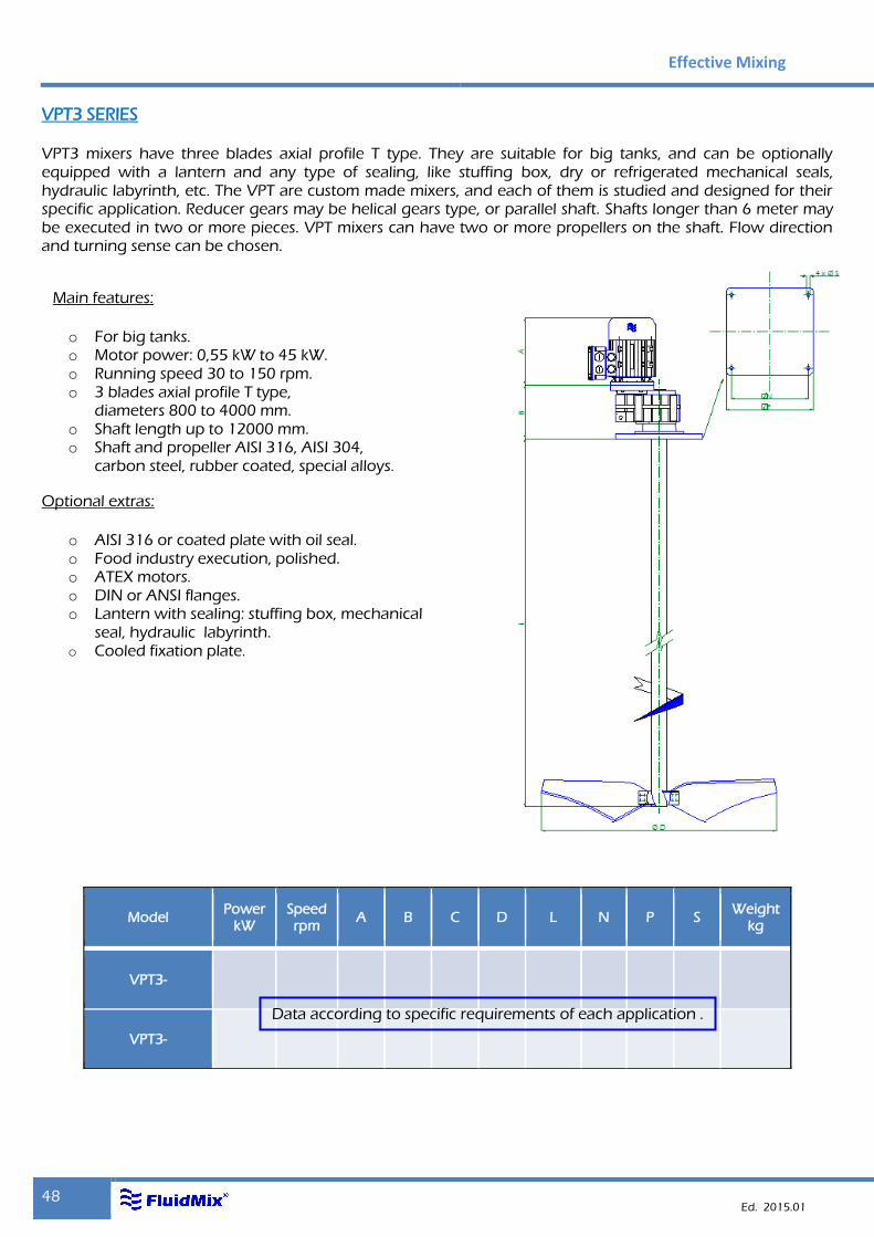
VPT3 SERIES
VPT3 mixers have three blades axial profile T type. They are suitable for big tanks, and can be optionally equipped with a lantern and any type of sealing, like stuffing box, dry or refrigerated mechanical seals, hydraulic labyrinth, etc. The VPT are custom made mixers, and each of them is studied and designed for their specific application. Reducer gears may be helical gears type, or parallel shaft. Shafts longer than 6 meter may be executed in two or more pieces. VPT mixers can have two or more propellers on the shaft. Flow direction and turning sense can be chosen.
Main features:
o For big tanks. o Motor power: 0,55 kW to 45 kW. o Running speed 30 to 150 rpm. o 3 blades axial profile T type,
diameters 800 to 4000 mm. o Shaft length up to 12000 mm. o Shaft and propeller AISI 316, AISI 304,
carbon steel, rubber coated, special alloys.
Optional extras:
o AISI 316 or coated plate with oil seal. o Food industry execution, polished. o ATEX motors. o DIN or ANSI flanges. o Lantern with sealing: stuffing box, mechanical
seal, hydraulic labyrinth. o Cooled fixation plate.
Model
Model Power
kW Speed rpm
A B C D L N P S Weight
kg
VPT3-
VPT3-
Data according to specific requirements of each application .
Mixers
49
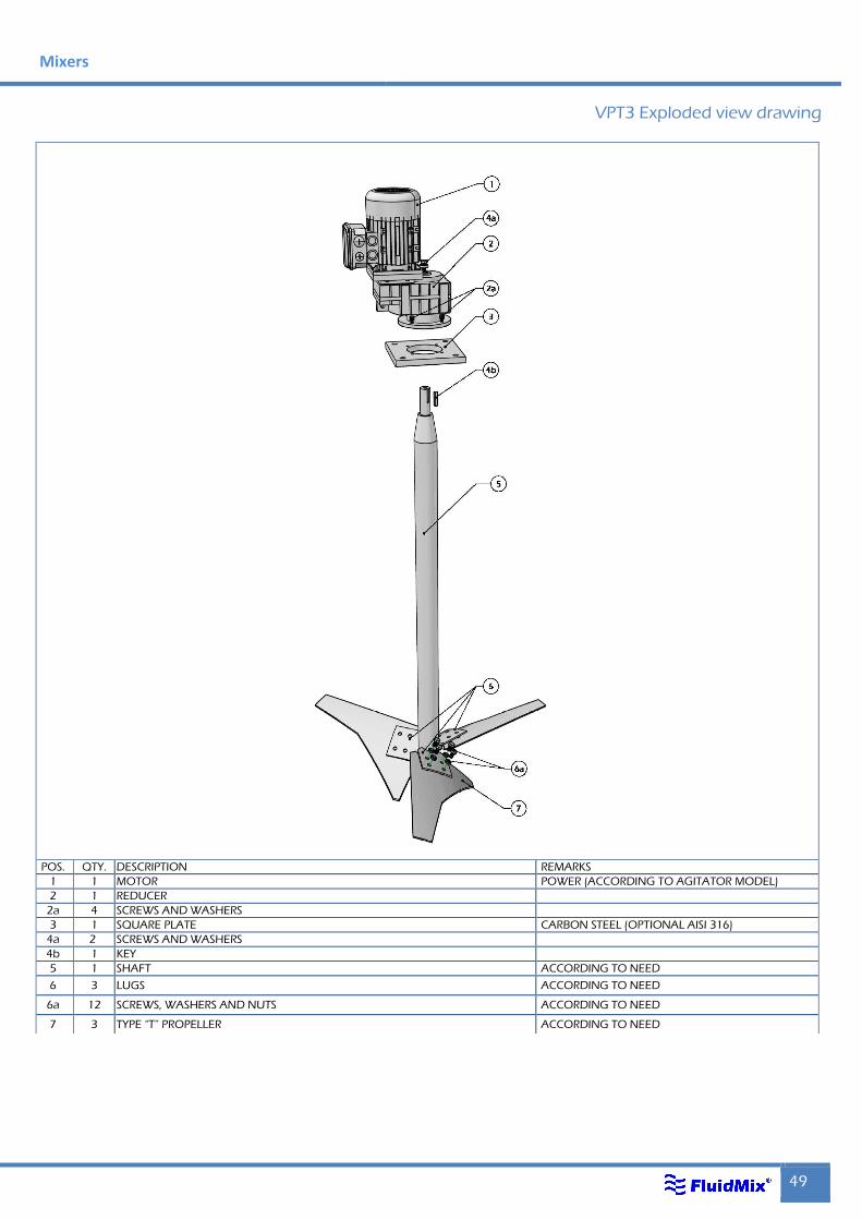
VPT3 Exploded view drawing
POS. QTY. DESCRIPTION REMARKS
1 1 MOTOR POWER (ACCORDING TO AGITATOR MODEL)
2 1 REDUCER
2a 4 SCREWS AND WASHERS
3 1 SQUARE PLATE CARBON STEEL (OPTIONAL AISI 316)
4a 2 SCREWS AND WASHERS
4b 1 KEY
5 1 SHAFT ACCORDING TO NEED
6 3 LUGS ACCORDING TO NEED
6a 12 SCREWS, WASHERS AND NUTS ACCORDING TO NEED
7 3 TYPE “T” PROPELLER ACCORDING TO NEED
Effective Mixing
50 Ed. 2015.01
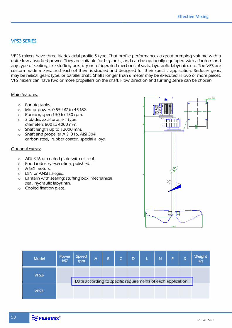
VPS3 SERIES
VPS3 mixers have three blades axial profile S type. That profile performances a great pumping volume with a quite low absorbed power. They are suitable for big tanks, and can be optionally equipped with a lantern and any type of sealing, like stuffing box, dry or refrigerated mechanical seals, hydraulic labyrinth, etc. The VPS are custom made mixers, and each of them is studied and designed for their specific application. Reducer gears may be helical gears type, or parallel shaft. Shafts longer than 6 meter may be executed in two or more pieces. VPS mixers can have two or more propellers on the shaft. Flow direction and turning sense can be chosen.
Main features:
o For big tanks. o Motor power: 0,55 kW to 45 kW. o Running speed 30 to 150 rpm. o 3 blades axial profile T type,
diameters 800 to 4000 mm. o Shaft length up to 12000 mm. o Shaft and propeller AISI 316, AISI 304,
carbon steel, rubber coated, special alloys.
Optional extras:
o AISI 316 or coated plate with oil seal. o Food industry execution, polished. o ATEX motors. o DIN or ANSI flanges. o Lantern with sealing: stuffing box, mechanical
seal, hydraulic labyrinth. o Cooled fixation plate.
Model Power
kW Speed rpm
A B C D L N P S Weight
kg
VPS3-
VPS3-
Data according to specific requirements of each application .
Mixers
51
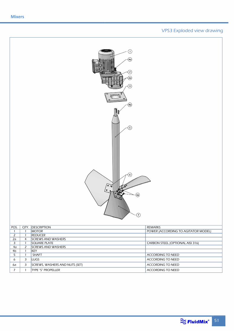
VPS3 Exploded view drawing
POS. QTY. DESCRIPTION REMARKS
1 1 MOTOR POWER (ACCORDING TO AGITATOR MODEL)
2 1 REDUCER
2a 4 SCREWS AND WASHERS
3 1 SQUARE PLATE CARBON STEEL (OPTIONAL AISI 316)
4a 2 SCREWS AND WASHERS
4b 1 KEY
5 1 SHAFT ACCORDING TO NEED
6 3 LUGS ACCORDING TO NEED
6a 3 SCREWS, WASHERS AND NUTS (SET) ACCORDING TO NEED
7 1 TYPE “S” PROPELLER ACCORDING TO NEED
Effective Mixing
52 Ed. 2015.01
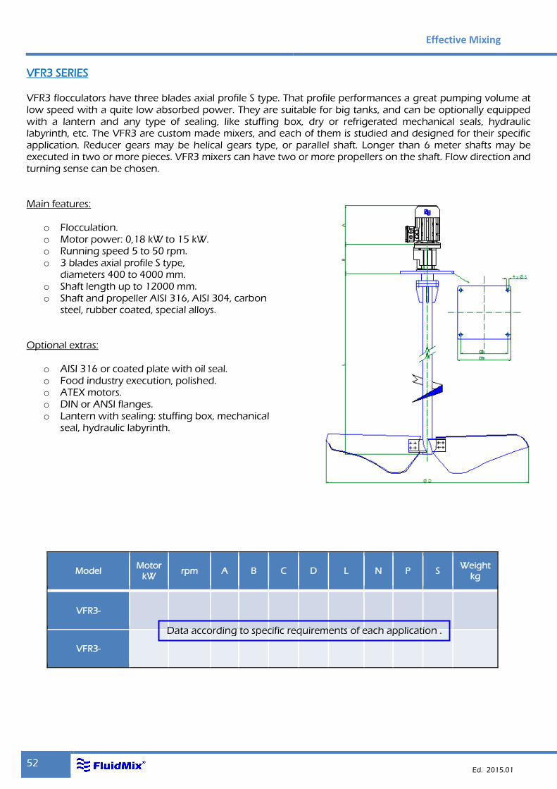
VFR3 SERIES
VFR3 flocculators have three blades axial profile S type. That profile performances a great pumping volume at low speed with a quite low absorbed power. They are suitable for big tanks, and can be optionally equipped with a lantern and any type of sealing, like stuffing box, dry or refrigerated mechanical seals, hydraulic labyrinth, etc. The VFR3 are custom made mixers, and each of them is studied and designed for their specific application. Reducer gears may be helical gears type, or parallel shaft. Longer than 6 meter shafts may be executed in two or more pieces. VFR3 mixers can have two or more propellers on the shaft. Flow direction and turning sense can be chosen. Main features:
o Flocculation. o Motor power: 0,18 kW to 15 kW. o Running speed 5 to 50 rpm. o 3 blades axial profile S type,
diameters 400 to 4000 mm. o Shaft length up to 12000 mm. o Shaft and propeller AISI 316, AISI 304, carbon
steel, rubber coated, special alloys. Optional extras:
o AISI 316 or coated plate with oil seal. o Food industry execution, polished. o ATEX motors. o DIN or ANSI flanges. o Lantern with sealing: stuffing box, mechanical
seal, hydraulic labyrinth.
Model Motor
kW rpm A B C D L N P S
Weight kg
VFR3-
VFR3-
Data according to specific requirements of each application .
Mixers
53
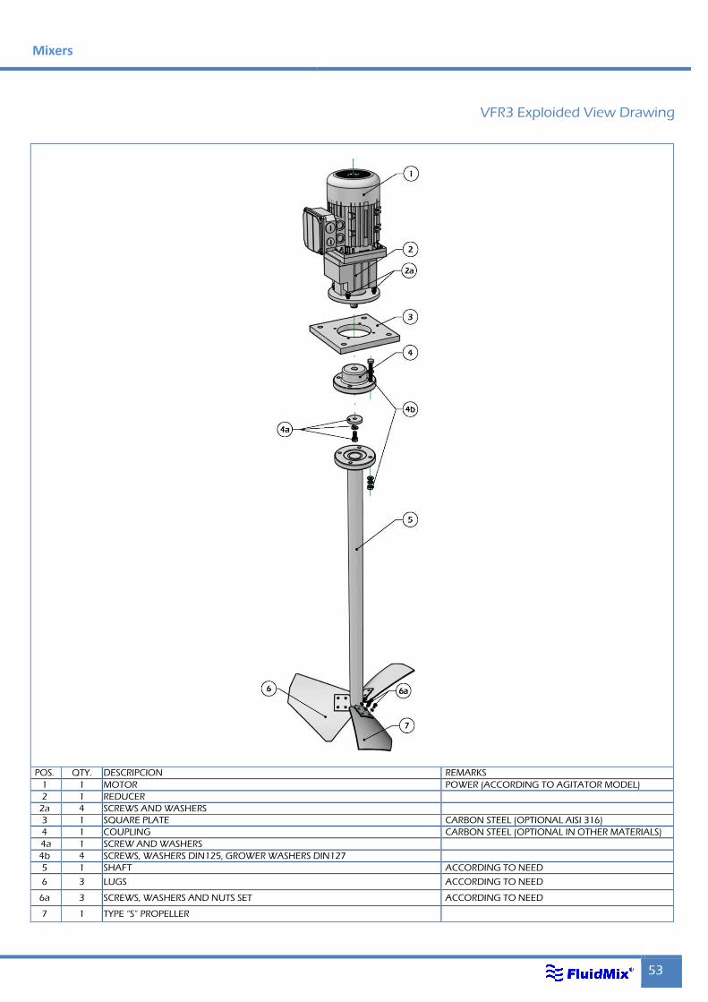
VFR3 Exploided View Drawing
POS. QTY. DESCRIPCION REMARKS
1 1 MOTOR POWER (ACCORDING TO AGITATOR MODEL)
2 1 REDUCER
2a 4 SCREWS AND WASHERS
3 1 SQUARE PLATE CARBON STEEL (OPTIONAL AISI 316)
4 1 COUPLING CARBON STEEL (OPTIONAL IN OTHER MATERIALS)
4a 1 SCREW AND WASHERS
4b 4 SCREWS, WASHERS DIN125, GROWER WASHERS DIN127
5 1 SHAFT ACCORDING TO NEED
6 3 LUGS ACCORDING TO NEED
6a 3 SCREWS, WASHERS AND NUTS SET ACCORDING TO NEED
7 1 TYPE “S” PROPELLER
Effective Mixing
54 Ed. 2015.01
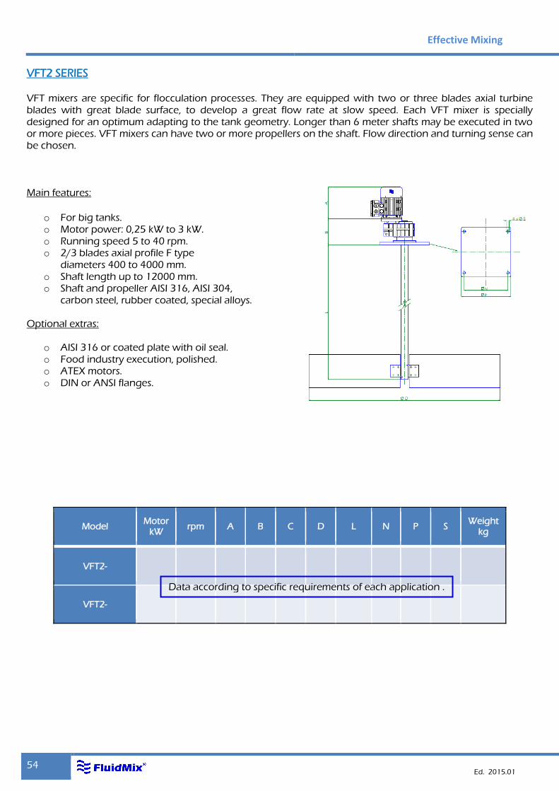
VFT2 SERIES
VFT mixers are specific for flocculation processes. They are equipped with two or three blades axial turbine blades with great blade surface, to develop a great flow rate at slow speed. Each VFT mixer is specially designed for an optimum adapting to the tank geometry. Longer than 6 meter shafts may be executed in two or more pieces. VFT mixers can have two or more propellers on the shaft. Flow direction and turning sense can be chosen. Main features:
o For big tanks. o Motor power: 0,25 kW to 3 kW. o Running speed 5 to 40 rpm. o 2/3 blades axial profile F type
diameters 400 to 4000 mm. o Shaft length up to 12000 mm. o Shaft and propeller AISI 316, AISI 304,
carbon steel, rubber coated, special alloys. Optional extras:
o AISI 316 or coated plate with oil seal. o Food industry execution, polished. o ATEX motors. o DIN or ANSI flanges.
Model Motor
kW rpm A B C D L N P S
Weight kg
VFT2-
VFT2-
Data according to specific requirements of each application .
Mixers
55
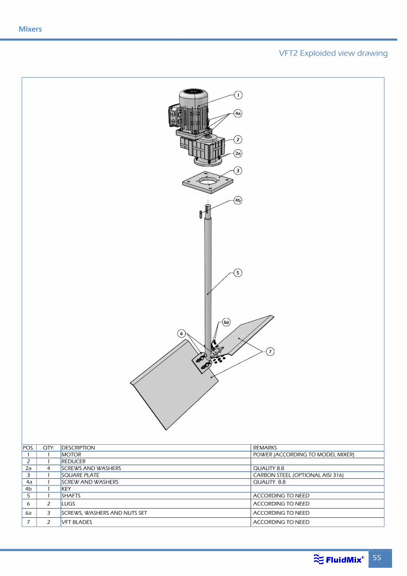
VFT2 Exploided view drawing
POS. QTY. DESCRIPTION REMARKS
1 1 MOTOR POWER (ACCORDING TO MODEL MIXER)
2 1 REDUCER
2a 4 SCREWS AND WASHERS QUALITY 8.8
3 1 SQUARE PLATE CARBON STEEL (OPTIONAL AISI 316)
4a 1 SCREW AND WASHERS QUALITY 8.8
4b 1 KEY
5 1 SHAFTS ACCORDING TO NEED
6 2 LUGS ACCORDING TO NEED
6a 3 SCREWS, WASHERS AND NUTS SET ACCORDING TO NEED
7 2 VFT BLADES ACCORDING TO NEED
Effective Mixing
56 Ed. 2015.01
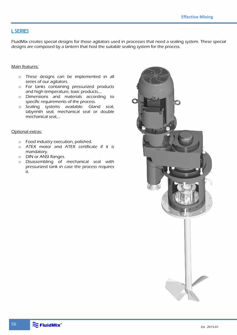
L SERIES
FluidMix creates special designs for those agitators used in processes that need a sealing system. These special designs are composed by a lantern that host the suitable sealing system for the process. Main features:
o These designs can be implemented in all series of our agitators.
o For tanks containing pressurized products and high temperature, toxic products,...
o Dimensions and materials according to specific requirements of the process.
o Sealing systems available: Gland seal, labyrinth seal, mechanical seal or double mechanical seal,...
Optional extras:
o Food industry execution, polished. o ATEX motor and ATEX certificate if it is
mandatory. o DIN or ANSI flanges. o Disassembling of mechanical seal with
pressurized tank in case the process requires it.
Mixers
57
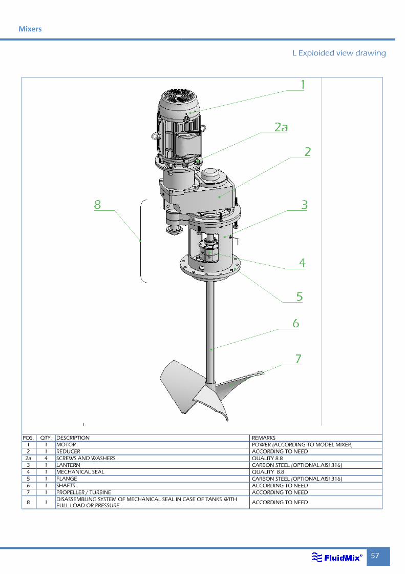
L Exploided view drawing
POS. QTY. DESCRIPTION REMARKS
1 1 MOTOR POWER (ACCORDING TO MODEL MIXER)
2 1 REDUCER ACCORDING TO NEED
2a 4 SCREWS AND WASHERS QUALITY 8.8
3 1 LANTERN CARBON STEEL (OPTIONAL AISI 316)
4 1 MECHANICAL SEAL QUALITY 8.8
5 1 FLANGE CARBON STEEL (OPTIONAL AISI 316)
6 1 SHAFTS ACCORDING TO NEED
7 1 PROPELLER / TURBINE ACCORDING TO NEED
8 1 DISASSEMBLING SYSTEM OF MECHANICAL SEAL IN CASE OF TANKS WITH FULL LOAD OR PRESSURE
ACCORDING TO NEED
Effective Mixing
58 Ed. 2015.01
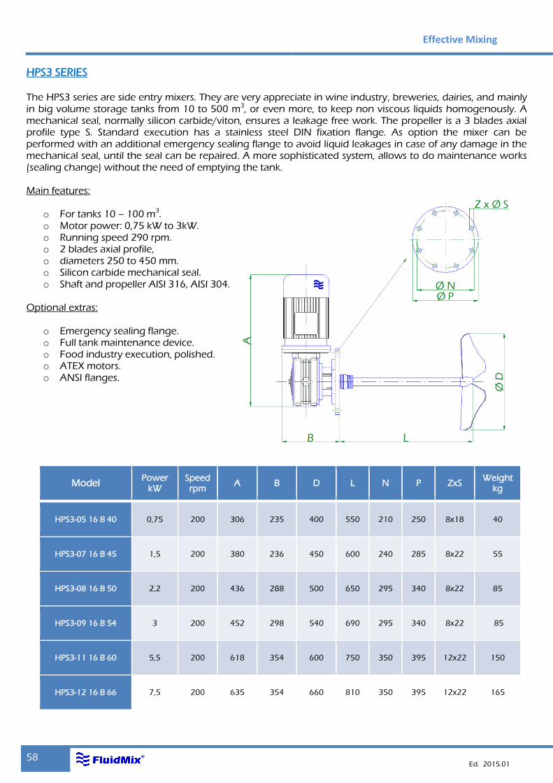
HPS3 SERIES
The HPS3 series are side entry mixers. They are very appreciate in wine industry, breweries, dairies, and mainly in big volume storage tanks from 10 to 500 m3, or even more, to keep non viscous liquids homogenously. A mechanical seal, normally silicon carbide/viton, ensures a leakage free work. The propeller is a 3 blades axial profile type S. Standard execution has a stainless steel DIN fixation flange. As option the mixer can be performed with an additional emergency sealing flange to avoid liquid leakages in case of any damage in the mechanical seal, until the seal can be repaired. A more sophisticated system, allows to do maintenance works (sealing change) without the need of emptying the tank. Main features:
o For tanks 10 – 100 m3. o Motor power: 0,75 kW to 3kW. o Running speed 290 rpm. o 2 blades axial profile, o diameters 250 to 450 mm. o Silicon carbide mechanical seal. o Shaft and propeller AISI 316, AISI 304.
Optional extras:
o Emergency sealing flange. o Full tank maintenance device. o Food industry execution, polished. o ATEX motors. o ANSI flanges.
Model Power
kW Speed rpm
A B D L N P ZxS Weight
kg
HPS3-05 16 B 40 0,75 200 306 235 400 550 210 250 8x18 40
HPS3-07 16 B 45 1,5 200 380 236 450 600 240 285 8x22 55
HPS3-08 16 B 50 2,2 200 436 288 500 650 295 340 8x22 85
HPS3-09 16 B 54 3 200 452 298 540 690 295 340 8x22 85
HPS3-11 16 B 60 5,5 200 618 354 600 750 350 395 12x22 150
HPS3-12 16 B 66 7,5 200 635 354 660 810 350 395 12x22 165
Mixers
59
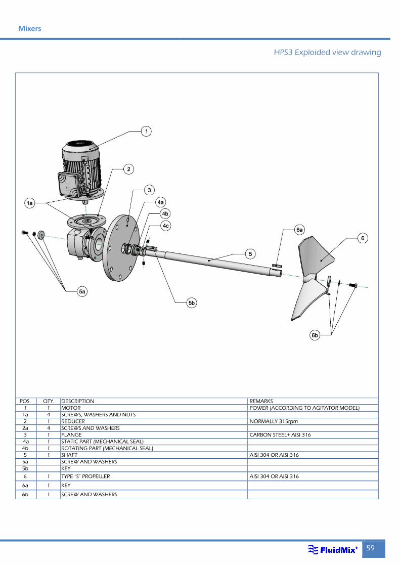
HPS3 Exploided view drawing
Sección
Reductor coaxial Reductor de eje hueco
POS. QTY. DESCRIPTION REMARKS
1 1 MOTOR POWER (ACCORDING TO AGITATOR MODEL)
1a 4 SCREWS, WASHERS AND NUTS
2 1 REDUCER NORMALLY 315rpm
2a 4 SCREWS AND WASHERS
3 1 FLANGE CARBON STEEL+ AISI 316
4a 1 STATIC PART (MECHANICAL SEAL)
4b 1 ROTATING PART (MECHANICAL SEAL)
5 1 SHAFT AISI 304 OR AISI 316
5a SCREW AND WASHERS
5b KEY
6 1 TYPE “S” PROPELLER AISI 304 OR AISI 316
6a 1 KEY
6b 1 SCREW AND WASHERS

Effective Mixing
60 Ed. 2015.01
Reducer section
Coaxial with helicoidal gears Hollow shaft with helicoidal gears
POS. DESCRIPTION POS. DESCRIPTION POS. DESCRIPTION
101 HOUSING 125 SHAFT SEAL 154 SHIM
102 COVER / HOUSING 126 RING 155 SHIM
103 GEAR 127 SHAFT SEAL 156 SHIM
104 PINION SHAFT / WORM SHAFT 128 SHAFT SEAL 157 SHIM
105 GEAR / WORM GEAR 129 SHAFT SEAL 158 BUSHING
106 HOLLOW SHAFT / SHAFT 130 COVER 159 SHIM
107 SHAFT / BUSHING 131 COVER 160 JOINT
108 SHAFT 132 COVER 161 JOINT
109 FLANGE 135 KEY 170 ALLEN SCREW
110 FLANGE 136 KEY 171 ALLEN SCREW
111 FOOT (ONLY GFL) 139 CIRCLIP 172 ALLEN SCREW
111 BEVEL GEAR SET (ONLY GKS) 140 CIRCLIP 173 ALLEN SCREW
112 SHRINK DISK 141 CIRCLIP 174 ALLEN SCREW
113 BUSHING 142 CIRCLIP 201 PUSH-IN PINION
115 TAPERED ROLLER BEARING 143 CIRCLIP 202 COVER
116 TAPERED ROLLER BEARING 144 CIRCLIP 203 ALLEN SCREW
117 DEEP GROOVE BALL BEARING / TAPERED ROLLER BEARING
145 CIRCLIP 204 JOINT
118 DEEP GROOVE BALL BEARING / TAPERED ROLLER BEARING
146 CIRCLIP 205 PIN
119 DEEP GROOVE BALL BEARING 150 SHIM 208 FILLER PLUG
120 TAPERED ROLLER BEARING 151 SHIM 209 FILLER PLUG
121 TAPERED ROLLER BEARING 152 SHIM
124 RING 153 SHIM
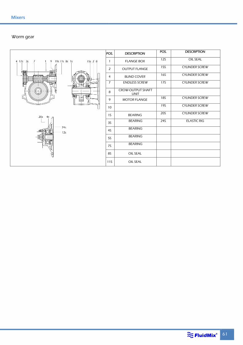
Mixers
61
Worm gear
POS. DESCRIPTION POS. DESCRIPTION
1 FLANGE BOX 12S OIL SEAL
2 OUTPUT FLANGE 15S CYLINDER SCREW
4 BLIND COVER 16S CYLINDER SCREW
7 ENDLESS SCREW 17S CYLINDER SCREW
8 CROW-OUTPUT SHAFT
UNIT
9 MOTOR FLANGE 18S CYLINDER SCREW
10 19S CYLINDER SCREW
1S BEARING 20S CYLINDER SCREW
3S BEARING 24S ELASTIC RIG
4S BEARING
5S BEARING
7S BEARING
8S OIL SEAL
11S OIL SEAL
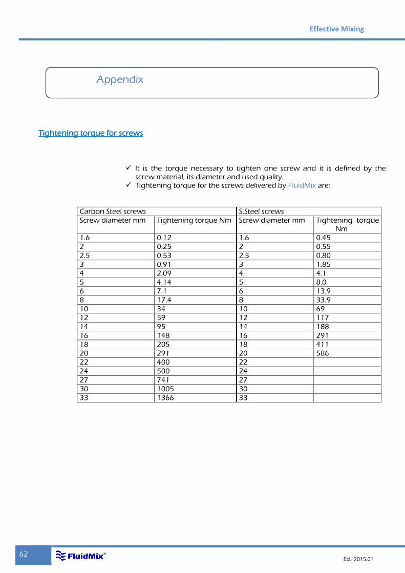
Effective Mixing
62 Ed. 2015.01
Appendix
Tightening torque for screws
It is the torque necessary to tighten one screw and it is defined by the screw material, its diameter and used quality.
Tightening torque for the screws delivered by FluidMix are:
Carbon Steel screws S.Steel screws
Screw diameter mm Tightening torque Nm Screw diameter mm Tightening torque Nm
1.6 0.12 1.6 0.45
2 0.25 2 0.55
2.5 0.53 2.5 0.80
3 0.91 3 1.85
4 2.09 4 4.1
5 4.14 5 8.0
6 7.1 6 13.9
8 17.4 8 33.9
10 34 10 69
12 59 12 117
14 95 14 188
16 148 16 291
18 205 18 411
20 291 20 586
22 400 22
24 500 24
27 741 27
30 1005 30
33 1366 33
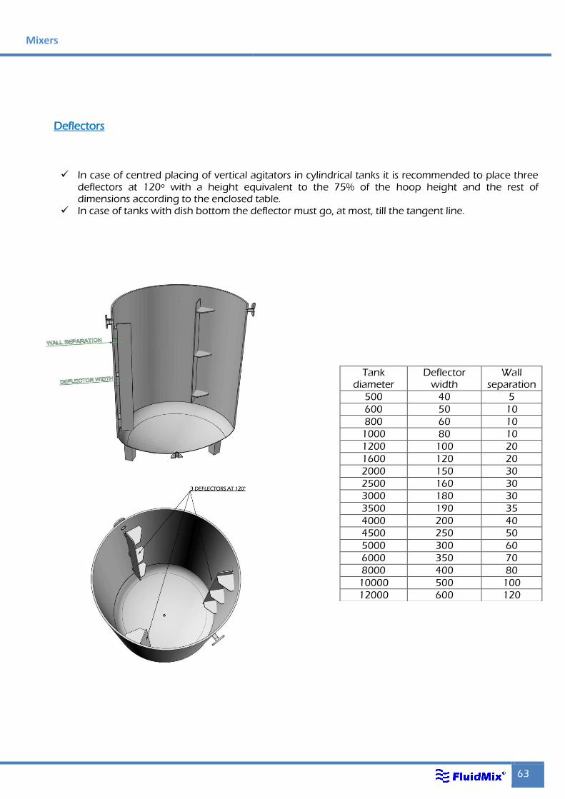
Mixers
63
Deflectors
In case of centred placing of vertical agitators in cylindrical tanks it is recommended to place three deflectors at 120º with a height equivalent to the 75% of the hoop height and the rest of dimensions according to the enclosed table.
In case of tanks with dish bottom the deflector must go, at most, till the tangent line.
Tank diameter
Deflector width
Wall separation
500 40 5
600 50 10
800 60 10
1000 80 10
1200 100 20
1600 120 20
2000 150 30
2500 160 30
3000 180 30
3500 190 35
4000 200 40
4500 250 50
5000 300 60
6000 350 70
8000 400 80
10000 500 100
12000 600 120
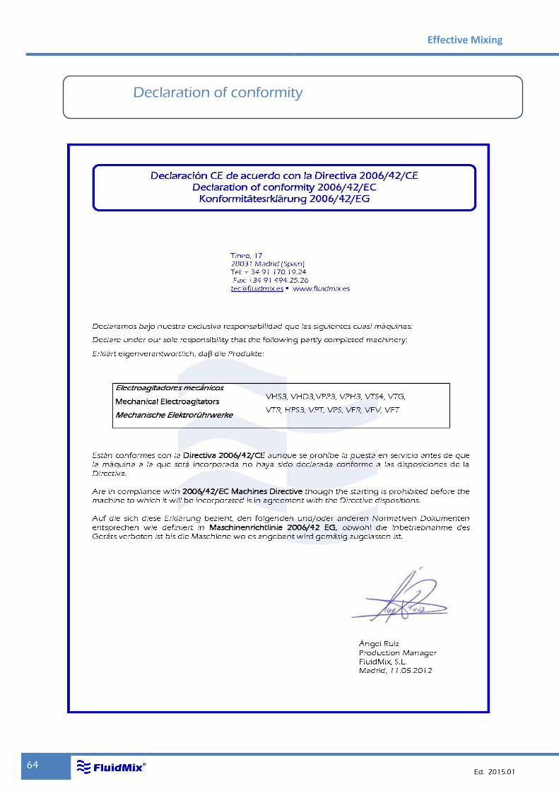
Effective Mixing
64 Ed. 2015.01
Declaration of conformity
800 60 10
1000 80 10
1200 100 20
1600 120 20
2000 150 30
2500 160 30
3000 180 30
3500 190 35
4000 200 40
4500 250 50
5000 300 60
6000 350 70
8000 400 80
10000 500 100
12000 600 120
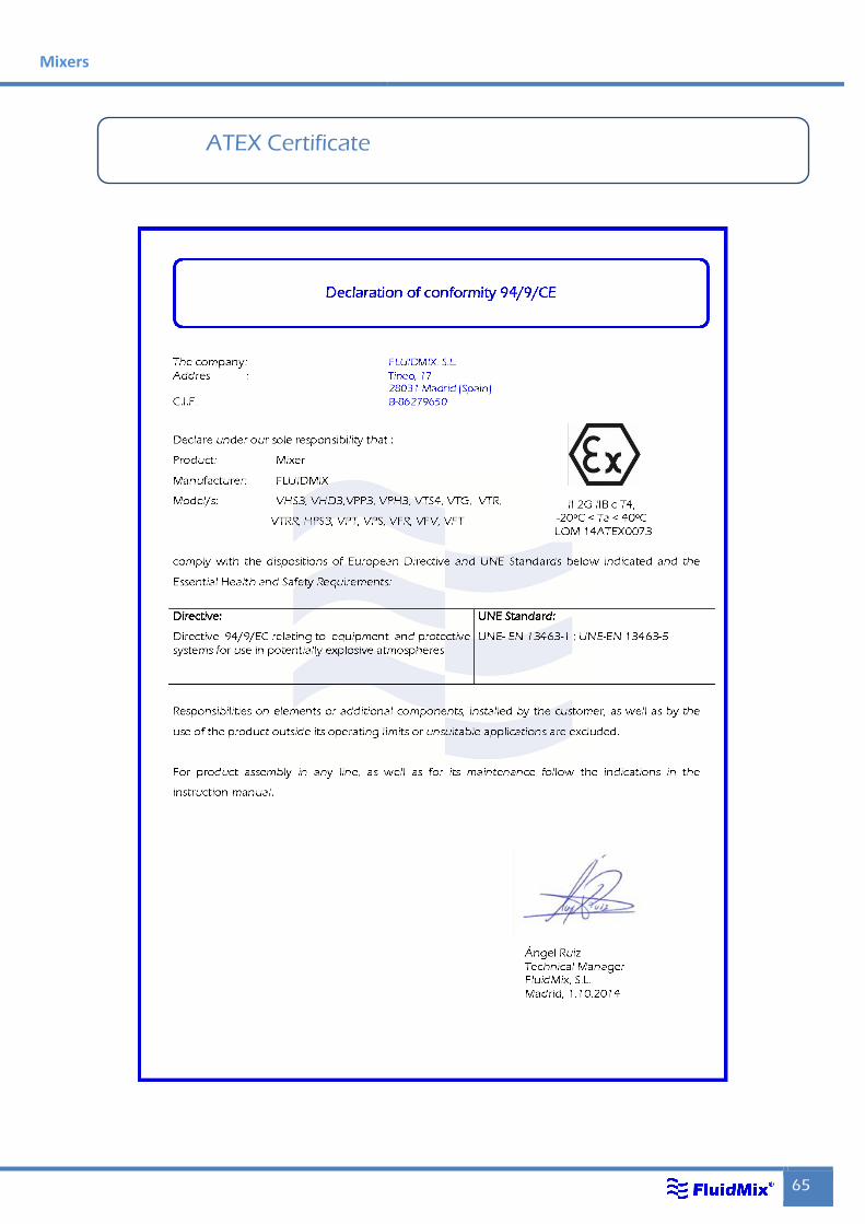
Mixers
65
ATEX Certificate

Effective Mixing
66 Ed. 2015.01
ISO 9001


Tineo 17 28031 Madrid Tel.: + 34 (9)1 170 19 24 Fax.: +34 (9)1 494 25 56 [email protected]
www.fluidmix.es