Embed Size (px)
Citation preview
User M
anual
Rock
well Automation Contr
olL
ogix
I/O
Mo
du
le
ADV ANC EDMIC RO CON T RO L S INC.
1241Resolver Interface Module
Manual #: 940-0C011

GENERAL INFORMATION
Important User InformationThe products and application data described in this manual are useful in a wide variety of different applica-tions. Therefore, the user and others responsible for applying these products described herein are responsible for determining the acceptability for each application. While efforts have been made to provide accurate information within this manual, AMCI assumes no responsibility for the application or the completeness of the information contained herein.
UNDER NO CIRCUMSTANCES WILL ADVANCED MICRO CONTROLS, INC. BE RESPONSIBLE OR LIABLE FOR ANY DAMAGES OR LOSSES, INCLUDING INDIRECT OR CONSEQUENTIAL DAM-AGES OR LOSSES, ARISING FROM THE USE OF ANY INFORMATION CONTAINED WITHIN THIS MANUAL, OR THE USE OF ANY PRODUCTS OR SERVICES REFERENCED HEREIN.
No patent liability is assumed by AMCI, with respect to use of information, circuits, equipment, or software described in this manual.
The information contained within this manual is subject to change without notice.
This manual is copyright 2002 by Advanced Micro Controls Inc. You may reproduce this manual, in whole or in part, for your personnal use provided that this copyright notice is included. You may distribute copies of this complete manual in electronic format provided that they are unaltered from the version posted by Advanced Micro Controls Inc. on our official website: www.amci.com. You may incorporate portions of this documents in other literature for use within the company that you own or are employed at provided that you include the notice “Portions of this document copyright 2002 by Advanced Micro Controls Inc.” You may not alter the contents of this document or charge a fee for reproducing or distributing it.
Standard WarrantyADVANCED MICRO CONTROLS, INC. warrants that all equipment manufactured by it will be free from defects, under normal use, in materials and workmanship for a period of [1] year. Within this warranty period, AMCI shall, at its option, repair or replace, free of charge, any equipment covered by this warranty which is returned, shipping charges prepaid, within one year from date of invoice, and which upon examina-tion proves to be defective in material or workmanship and not caused by accident, misuse, neglect, alteration, improper installation or improper testing.
The provisions of the "STANDARD WARRANTY" are the sole obligations of AMCI and excludes all other warranties expressed or implied. In no event shall AMCI be liable for incidental or consequential damages or for delay in performance of this warranty.
Returns PolicyAll equipment being returned to AMCI for repair or replacement, regardless of warranty status, must have a Return Merchandise Authorization number issued by AMCI. Call (860) 585-1254 with the model number and serial number (if applicable) along with a description of the problem. A "RMA" number will be issued. Equipment must be shipped to AMCI with transportation charges prepaid. Title and risk of loss or damage remains with the customer until shipment is received by AMCI.
24 Hour Technical Support Number24 Hour technical support is available on this product. For technical support, call (860) 583-7271. Your call will be answered by the factory during regular business hours, Monday through Friday, 8AM - 5PM EST. During non-business hours an automated system will ask you to enter the telephone number you can be reached at. Please remember to include your area code. The system will page one of two engineers on call. Please have your product model number and a description of the problem ready before you call.
We Want Your FeedbackManuals at AMCI are constantly evolving entities. Your questions and comments on this manual are both welcomed and necessary if this manual is to be improved. Please direct all comments to: Technical Docu-mentation, AMCI, 20 Gear Drive, Terryville CT 06786, or fax us at (860) 584-1973. You can also e-mail your questions and comments to [email protected]
ADVANCED MICRO CONTROLS INC.

TABLE OF CONTENTS
General InformationImportant User Information ..................... IFCStandard Warranty ................................... IFCReturns Policy .......................................... IFC24 Hour Technical Support Number ........ IFCWe Want Your Feedback ......................... IFC
About This ManualAudience .................................................. 5Navigating this Manual ............................ 5Manual Conventions ................................ 5Trademarks and Other Legal Stuff .......... 6Revision Record ....................................... 6
Revision History ............................ 6
Where To Go From Here ......................... 6
Chapter 1: Introduction to the 1241Overview .................................................. 7Module Description ................................. 7
Status LED’s .................................. 8
Stop Time Monitoring ............................. 8Compatible Transducers .......................... 9Other AMCI ControlLogix Products ....... 10Other AMCI Products .............................. 11
Chapter 2: Quick StartGet Familiar With the 1241 ..................... 13Decide On Needed Functionality ............. 13Determine Parameter Values ................... 13Install Hardware ....................................... 13Configure Your RSLogix 5000 Software 14Add Ladder Logic to Program the 1241 .. 14Verify and Fine Tune Your System ......... 14
Chapter 3: System CheckoutNeeded Equipment ................................... 15Install the Modules in the Chassis ........... 15Faking a Transducer, or
Attaching a Real One ............................. 15Attach the PC to the Processor ................ 16Apply Power ............................................ 16Create a New Project ............................... 16Configure the 1241’s Slot ........................ 16
Chapter 3: System Checkout(continued)
Add a Message Instruction Controller Tag ........................................ 16
Add a Message Instruction Data Tag ....... 16Create a “send” Tag ................................. 17Add Ladder Logic .................................... 17Download the Program and
Switch to Run Mode .............................. 18Monitor Your Data Values ....................... 18Preset the Data Value ............................... 18
What’s Going On .......................... 18
Chapter 4: SpecificationsSpecification Sheet ................................... 19Functionality Overview ............................ 20Stop Time Monitoring .............................. 21Hardware Specifications .......................... 22
Status LED’s ................................. 22Transducer Input Connector ......... 22Brake Input Connector .................. 23
Module Parameters ................................... 23Full Scale Count ............................ 23Circular Offset .............................. 23Linear Offset ................................. 24Preset Value .................................. 24COS Interrupt Enable .................... 24Count Direction ............................. 24Tachometer Response ................... 25Transducer Fault Latch ................. 25Resolver Type ............................... 25
Parameter Defaults and Ranges ............... 25RSLogix Message Instruction .................. 26‘Setup Data’ Message Format .................. 26‘Apply Preset’ Message Format ............... 27‘Clear Transducer Fault’ Message Format 27Message Instruction Error Codes ............. 27Input Data Format .................................... 28Transducer Cable Specification ............... 28CTL-(x) Specifications ............................. 29CTLR-(x) Specifications .......................... 29Transducer Specifications ........................ 30Transducer Connector Pinout ................... 30
20 Gear Drive, Plymouth Ind. Park, Terryville, CT 06786Tel: (860) 585-1254 Fax: (860) 584-1973 http://www.amci.com
3

Chapter 5: General Installation Guidelines
Background .............................................. 31Surge (EMI) Suppression ......................... 31
Surge Suppression: DC Outputs ... 32Surge Suppression: AC Outputs ... 33
Grounding ................................................. 34Wiring ....................................................... 34Power Supply Wattage and Filtering ....... 35
Chapter 6: Installing the 1241Installing the Module ............................... 37Transducer Cable Installation ................... 37
CTL-(x) Wiring Diagram .............. 38CTLR-(x) Wiring Diagram ........... 38
Transducer Installation ............................. 39Transducer Outline Drawings ....... 39Transducer Mounting .................... 39Autotech Transducers ................... 39
Brake Input Wiring ................................... 39Input Connector ............................ 39Connector Wiring ......................... 40
Chapter 7: RSLogix 5000 Configuration
A Word About Message Instructions ....... 41Open Your Project .................................... 41Configure the 1241’s Slot ........................ 41Add a Controller Tag For Each
Message Instruction ............................... 42Add Controller Tags for the 1241 Data .... 42Add Message Instructions to
Ladder Logic .......................................... 43Configure the Message Instruction .......... 44
Chapter 8: DATA FORMATInput Data ................................................. 45
I.Data[0] Bit Descriptions ............. 45
Setup Data Message Format ..................... 46Bit Descriptions ............................ 46
Apply Preset Message Format .................. 47Bit Description .............................. 47
Clear Transducer Fault Message Format . 47
Chapter 9: SAMPLE PROGRAMAbout the Program .................................... 49Message Instruction Configurations ......... 49
Setup Data Message ...................... 49Apply Preset Message ................... 49Clear Transducer Fault Message ... 49
Program Listing ........................................ 50Error Checking ......................................... 51
Extended Error Codes ................. 51
ADVANCED MICRO CONTROLS INC.4

ABOUT THIS MANUAL
AudienceThis manual explains the set-up, installation, and operation of AMCI’s 1241 Resolver Interface Module for the Rockwell Automation ControlLogix PLC platform.
It is written for the engineer responsible for incorporating the 1241 into a design, as well as the engineer or technician responsible for its actual installation.
Navigating this ManualThis manual is designed to be used in both printed and on-line forms. Its on-line form is a PDF document, which requires Adobe Acrobat Reader version 4.0+ to open it.
Bookmarks of all the chapter names, section headings, and sub-headings are in the PDF file to help you navi-gate through it. The bookmarks should have appeared when you opened the file. If they didn’t, press the F5 key on Windows platforms to bring them up.
Throughout this manual you will also find green text that functions as a hyperlink in HTML documents. Clicking on the text will immediately jump you to the referenced section of the manual. If you are reading a printed manual, most links include page numbers.
The PDF file is password protected to prevent changes to the document. You are allowed to select and copy sections for use in other documents and, if you own Adobe Acrobat version 4.05 or later, you are allowed to add notes and annotations.
Manual ConventionsThree icons are used to highlight important information in the manual:
NOTES highlight important concepts, decisions you must make, or the implications of those decisions.
CAUTIONS tell you when equipment may be damaged if the procedure is not followed properly.
WARNINGS tell you when people may be hurt or equipment may be damaged if the pro-cedure is not followed properly.
The following table shows the text formatting conventions:
Read this chapter to learn how to navigate through the manual and familiarize yourself with theconventions used in it. The last section of this chapter highlights the manual’s remaining chaptersand their targeted audiences.
Format Description
Normal Font Font used throughout this manual.
Emphasis Font Font used the first time a new term is introduced.
Cross Reference When viewing the PDF version of the manual, clicking on the cross reference text jumps you to referenced section.
20 Gear Drive, Plymouth Ind. Park, Terryville, CT 06786Tel: (860) 585-1254 Fax: (860) 584-1973 http://www.amci.com
5

ABOUT THIS MANUAL
Trademarks and Other Legal StuffThe AMCI logo is a trademark, and “AMCI” and “DuraCoder” are registered trademarks of Advanced Micro Controls Inc. “Allen-Bradley”, “ControlLogix”, “RSLogix 5000”, and “Rockwell Software” are trademarks of Rockwell Automation. “Adobe” and “Acrobat” are registered trademarks of Adobe Systems Incorporated.
All other trademarks contained herein are the property of their respective holders.
This product incorporates technology which is licensed from Allen-Bradley Company, LLC. Allen-Bradley has not technically approved, nor does it warrant or support this product. All warranty and support for this product and its application is provided solely by Advanced Micro Controls Inc.
Revision RecordThis manual, 940-0C011, is the first revision of the manual. It was initially released January 22, 2003. It changes the current draw specifications to reflect the changes made to the module starting with serial number 77364. Starting with the serial number, all 1241’s use only the 5 volt DC supply from the backplane. The use of the 24Vdc supply has been eliminated. This eliminates a RIUP (Removal and Insertion Under Power) problem that Rockwell Automation has discovered with all ControlLogix modules that use the 24Vdc back-plane supply. This revision also changes the sample program in chapter 9 of this manual.
Revision History940-0C011: 1/22/2003. RIUP and Sample Program changes.
940-0C010: 7/17/2002. Initial Release.
Where To Go From HereThis manual contains information that is of interest to everyone from engineers to operators. The table below gives a brief description of each chapter’s contents to help you find the information you need to do your job.
CHP Num. Chapter Title Intended Audience
1 INTRODUCTION TO THE 1241
Anyone new to the 1241. This chapter gives a basic overview of the features available on the unit, typical applications, and comple-mentary equipment.
2 QUICK START Anyone already experienced in installing or using similar products and wants generalized information to get up and running quickly.
3 SYSTEM CHECKOUT A bench test procedure to help you get familiar with the 1241.
4 SPECIFICATIONSAnyone that needs detailed information on the 1241 including elec-trical specifications and an explanation of its programmable parameters.
5GENERAL
INSTALLATION GUIDELINES
Anyone new to installing electronic controls in an industrial envi-ronment. The chapter includes general information on grounding, wiring, and surge suppression that is applicable to any controls installation.
6 INSTALLING THE 1241
Anyone that must install a 1241. Includes information on mount-ing, grounding, and wiring specific to the unit.
7RSLOGIX 5000
CONFIGURATIONAnyone that must configure the RSLogix 5000 package to commu-nicate with the 1241.
8 DATA FORMATAnyone responsible for developing the ladder logic to control the 1241 or anyone that needs to determine the meaning of the data transmitted by the 1241.
9 SAMPLE PROGRAM Anyone that must develop the ladder logic to read and write data to the 1241.
ADVANCED MICRO CONTROLS INC.6

20 Gear Drive, Plymouth IndTel: (860) 585-1254 Fax: (8
CHAPTER 1
INTRODUCTION TO THE 1241OverviewThe 1241 is the first resolver interface module for Rockwell Auto-mation’s ControlLogix platform. The module converts resolver signals to digital position and tachometer data that is reported over the backplane. Status information is also reported. The 1241 elim-inates the separate resolver decoder box, input card, and associated wiring needed to bring resolver data into a PLC.
Like an absolute optical encoder, a resolver is a sensor that con-verts an angle into electrical signals. However, this is where the similarities end. The resolver is an analog device that does not contain sensitive components such as optics and electronics that may be damaged by severe environmental conditions. Also, the position resolution of a resolver is limited only by the electronics that decode its signals. When attached to a 1241 module, the resolver gives an absolute position value with up to thirteen bits of position resolution over a six conductor cable. An absolute optical encoder would require a cable with at least fifteen wires to accom-plish the same resolution.
A 1241 application generally falls into one of two categories.
Rotary Application - The resolver position directly corre-lates to an angular position on the machine. One example is monitoring a press ram. As the press cycles through one turn, the resolver position is used to monitor and control such functions as material feed and part blow-off.
Linear Application - The resolver position correlates to a physical length. These applications can be either single turn or multi-turn. An example of a single turn application is a packaging machine where the resolver completes one turn for each product. An example of a multi-turn application is monitoring the position of a load on a track or ball screw. In this type of application, linear position is translated to rotary position through a wheel or gearing. The transducer completes several rotations in order to travel the entire distance.
The 1241 also has a Stop Time Monitor feature. This feature measure the time between a transition on the front panel Brake Input and the stopping of the transducer rotation. The Stop Time Monitor is typically used in press controls but can be used in any application where you need to monitor the stopping time of the resolver. Some other application examples are overhead cranes and mining cars.
Module DescriptionAs you can see in figure 1.1, the 1241 is very simple. There are two status LED’s in the display and two con-nectors behind the door. The eight pin connector is the Transducer Input Connector and the two pin connector is the Brake Input Connector. The LED above this connector is a status LED for the input.
AMCI purchases the case pieces, backplane connector, and backplane interface IC directly from Rockwell Automation under license. These are the same components used by Rockwell Automation products, so the 1241 is 100% mechanically and electrically compatible with the ControlLogix system.
Figure 1.1 1241 Module
. Park, Terryville, CT 0678660) 584-1973 http://www.amci.com
7

INTRODUCTION1
Module Description (continued)Status LED’sThe two Status LED’s allow you to quickly verify the operating status of the module. The OK LED shows the state of the communications between the 1241 and the back-plane. (It’s actually controlled by the A-B interface IC.) It does not indicate the working state of the module.
The STATUS LED shows the working state of the module. Any problem with the module itself will cause this LED to turn on red. A problem with the transducer is indicated by blinking the LED. When it blinks green, the transducer signals were temporarily lost but the transducer is now working. This is most commonly caused by a loose connection or a burst of electrical noise. If the LED blinks red, the trans-ducer is not sending back correct signals to the module. This can be caused by improper wiring or a faulty transducer.
A more in-depth description of the status LED’s is given in the Hardware Specifications section of chapter 4, starting on page 22.
Stop Time MonitoringIf you are using the 1241 in a press control application, you can use the stop time monitoring feature to mea-sure the stopping time of the crankshaft. The stop time monitor on the unit measures the time between the on-to-off transition of the Brake Input and the stopping of the transducer. The Stop Time Timer measures a stop-ping time of 34 milliseconds to 64.140 seconds with a resolution of 1 millisecond.
The 1241 also captures the position at which the brake is applied and reports this information, along with the stopping time, when a brake cycle is completed. This information is reported over the backplane until the next brake cycle finishes.
If you are not using the unit in a press control application or any other application that requires you to monitor the Stopping time of your machine, then you can leave the Brake Input un-wired and the Stop Time Monitor will never trigger.
The stop time monitor is a monitoring feature only. Any determination of the correct operation of the brakemust be made by the system PLC through a user developed ladder logic program.
Figure 1.2 Status LED’s
ADVANCED MICRO CONTROLS INC.8

INTRODUCTION 1
Compatible TransducersTable 1.1 lists the AMCI single-turn transducers that are compatible with the 1241.
† Available gear ratios are: 2:1, 2.5:1, 2.77:1, 3:1, 4:1, 4.8:1, 5:1, 6:1, 7:1, 8:1, 9:1, 10:1, 12:1, 13:1, 15:1, 16:1, 18:1, 20:1, 24:1, 36:1, 40:1, 50:1, 60:1, 64:1, 100:1, 105:1, 150:1, 180:1, 250:1 and 256:1. Additional gear ratios may be available. Check our website, www.amci.com, for an up-to-date listing.
‡ This package contain two resolvers geared 1:1 with the input shaft. Most commonly used in systems that man-date redundant sensors, AMCI can install two different size 11 resolvers in the package per customer require-ments. Contact AMCI for more information.
Table 1.1 Compatible Transducers
Model Shaft Mount Turns Comments
R11X-J10/7 0.120" Servo 1 NEMA 1, size 11 resolver. Leads only, no connector.
R11X-J10/7G 0.120" Servo 1 Same as R11X-J10/7 with AMCI’s standard single turn connector wired to the resolver.
R11X-J12/7 0.188" Servo 1 NEMA 1, size 11 resolver. Leads only, no connector.
R11X-J12/7G 0.188" Servo 1 Same as R11X-J12/7 with AMCI’s standard single turn connector wired to the resolver.
HT-6 0.188" Front/Side 1 NEMA 13 R11X-J12/7 transducer
HT-20 0.625" Front/Side 1 NEMA 4 heavy duty transducer
HT-20S 0.625" Front/Side 1 HT-20 with side connector
HT-20C 0.625" Front/Side 1NEMA 4X stainless steel HT-20 w/ Viton® shaft seal, and 0.5" NPT thread for conduit connection. Internal terminal plug for resolver connections.
HT-20K 0.625" Front/Side 1 NEMA 4X hard coat anodized HT-20, stainless steel shaft w/ Viton shaft seal.
HT-20KS 0.625" Front/Side 1 HT-20K with side connector.
HT-20L 0.625" Front/Side 1 NEMA 4X hard coat anodized HT-20, stainless steel shaft w/ Nitrile shaft seal.
HT-20LS 0.625" Front/Side 1 HT-20L with side connector.
H25-FE 0.375" Flange 1 NEMA 4, size 25, end connector
H25-F1E 0.375" Flange 1 NEMA 4, size 25, end connector. Bolt-in replace-ment for Namco/C&A HT-11B transducers.
H25-FS 0.375" Flange 1 NEMA 4, size 25, side connector
H25-FL 0.375" Flange 1 NEMA 4, size 25, integral 15 foot (3 meter) cable
H25-SE 0.375" Servo/Front 1 NEMA 4, size 25, end connector
H25-SS 0.375" Servo/Front 1 NEMA 4, size 25, side connector
H25-SL 0.375" Servo/Front 1 NEMA 4, size 25, integral 15 foot (3 meter) cable
HT-400 0.625" Front 1NEMA 4, Bolt-in replacement for Autotech RL100 transducers. Also has HT-20 bolt pattern. 1" NPT thread for conduit connection. Internal terminal strip for resolver connections.
HT-400-1E 0.625" Front 1 Same as HT-400 with an AMCI MS connector instead of a conduit connection.
HT-20-(x) 0.625" Front (x)† HT-20 with internal (x):1 gear ratio
HTT-20-1 0.625" Front 1‡ Redundant single turn resolvers, single MS connec-tor
HTT-400-1 0.625" Front 1‡Redundant single turn resolvers. Bolt-in replace-ment for Autotech RL220 transducers. Dual AMCI MS connectors.
20 Gear Drive, Plymouth Ind. Park, Terryville, CT 06786Tel: (860) 585-1254 Fax: (860) 584-1973 http://www.amci.com
9

INTRODUCTION1
Other AMCI ControlLogix ProductsAMCI has a growing line of products for the ControlLogix platform and the ControlNet network. Table 1.2 gives a brief description of these products. Additional information on these units can be found on our web-site, www.amci.com.
Table 1.2 Other ControlLogix Products
Model Number Interface Description
1242 ControlLogixResolver Interface Module. Similar to the 1241 in functionality, the 1242 can be configured to accept 2 single-turn transducers or 1 dual resolver, absolute multi-turn transducer.
8213 ControlLogix
Resolver based Programmable Limit Switch. This programmable limit switch turns outputs on and off based on the resolver’s position and speed. The 8213 has 16 limit switch outputs available over the back-plane and 16 available off a relay board that attaches to the module. Two velocity based analog outputs are also available.
3202 ControlLogix
Two channel stepper indexer module for the ControlLogix backplane with incremental encoder position feedback. Featuring blended move profiles and profiles based on encoder feedback, the module also has multiple inputs for homing and over travel protection. AMCI also has a full line of drives and motors to complete your stepper motor system.
3204 ControlLogixFour channel stepper indexer module for the ControlLogix backplane. Featuring blended move profiles, the module also has multiple inputs for homing and over travel protection. AMCI also has a full line of drives and motors to complete your stepper motor system.
NX2A4C ControlNetResolver Interface unit. Accepts 4 single resolver transducers or 2 dual resolver, absolute multi-turn transducers. Reports position, velocity, and fault diagnostic data. The unit also has a Brake Input for stop time monitoring.
NX2C4C ControlNet Four channel LDT interface. Accepts AMCI, Balluff, and Temposonic transducers. Reports position, velocity, and fault diagnostics.
NX2C4C-08 ControlNet Four channel multiple magnet LDT interface. Same as the NX2C4C except it allows up to sixteen magnets per transducer.
NX2E4C ControlNetFour channel SSI interface. Accepts any transducer that outputs SSI data. Supports 1 to 32 bit transfers with a data value programmable from 1 to 28 bits. Reports Data Value, Rate of Change, fault diagnos-tics, and raw SSI data.
NX3B1C ControlNetOne resolver input, programmable limit switch. Sixteen digital inputs and sixteen solid state relay outputs. Eight outputs available on-board, additional eight output available from an external relay board.
NX1F2C ControlNetTwo axis stepper indexer. With features similar to the 3202 module, this unit allows you to place the indexer where you need it, thereby sim-plifying wiring on large installations. The ControlNet interface also makes it easy to use the NX1F2C in PLC-5 and SLC500 systems.
NX1F4C ControlNetFour axis stepper indexer. With features similar to the 3202 module, this unit allows you to place the indexer where you need it, thereby sim-plifying wiring on large installations. The ControlNet interface also makes it easy to use the NX1F4C in PLC-5 and SLC500 systems.
SD17098IC ControlNet
Stepper Drive / Indexer Combination with integrated ControlNet inter-face. Programmable over ControlNet or an RS-232/485 port, this microstepping drive is designed for size 23 through 42 motors and fea-tures RMS current control, a 170Vdc output bus and up to 9.8A of motor current. Designed to save the cost of a separate indexer module for applications that are already using ControlNet, the indexer supports blended move profiles as well as velocity mode programming.
ADVANCED MICRO CONTROLS INC.10

INTRODUCTION 1
Other AMCI ProductsAMCI has been serving the industrial automation sector since 1985, and we have a broad range of other prod-ucts used throughout the market.
DURACODERS: Absolute, Analog, or Incremental encoders that replace the fragile glass disk and sen-sitive optics with an industrial resolver. The size 25 DuraCoders are drop in replacements for similar sized optical encoders.
STEPPER MOTION: Our line of stepper products that includes motors, drives, and indexers. Stepper motor systems offer low cost motion control for many packaging machines.
PLC PLUG-IN MODULES: AMCI offers a broad range of PLC plug-in modules for most major PLC brands including Rockwell Automation’s SLC500 and 1771 I/O, GE Fanuc 90-70 and 90-30, and Mod-icon Quantum. Modules include resolver, LDT, and SSI interfaces, programmable limit switches, and registration control modules.
RESOLVER TRANSDUCERS: AMCI is the only company in the market place to manufacturer its own resolvers. Not only do we make the resolvers for our own products, we also produce resolvers with dif-ferent electrical specifications for other position feedback applications such as servo control.
For additional information on these items and the rest of our product lines, browse through our website www.amci.com, or contact AMCI or your local AMCI distributor.
20 Gear Drive, Plymouth Ind. Park, Terryville, CT 06786Tel: (860) 585-1254 Fax: (860) 584-1973 http://www.amci.com
11

INTRODUCTION1
NotesADVANCED MICRO CONTROLS INC.12

20 Gear Drive, Plymouth IndTel: (860) 585-1254 Fax: (8
CHAPTER 2
QUICK STARTSTEP 1: Get Familiar With the 12411.1) Chapter 4, SPECIFICATIONS, chapter 7, RSLOGIX 5000 CONFIGURATION, and chapter 8,
DATA FORMAT, contain all of the information you’ll need to know to program the module.
1.2) Chapter 3, SYSTEM CHECKOUT walks you through a bench test of the 1241.
STEP 2: Decide On Needed Functionality2.1) Will you use the Brake Input? If you do, you’ll have to develop the circuit to wire into the input.
See the Brake Input Wiring section of chapter 6 starting on page 39 for wiring suggestions. The input triggers when the input transitions from on-to-off. If you’re not using the input, then there is nothing to do. Don’t wire anything to the input and it won’t trigger.
STEP 3: Determine Parameter Values3.1) The 1241’s parameters are described in the Module Parameters section of chapter 4 starting on
page 23. Table 4.1, Factory Defaults and Ranges, on page 25 lists the acceptable values for each parameter.
STEP 4: Install Hardware4.1) The 1241 installs in the ControlLogix chassis like every other I/O module.
4.2) The part number of the transducer cable is CTL-(x), where ‘x’ is its length in feet. Note that it’s a low power cable and must not be routed with high power AC or DC cabling. Chapter 5, GENERAL INSTALLATION GUIDELINES, which starts on page 31, contains information on installing the cable.The figure below shows how to wire the CTL to the 1241’s included transducer input connector.
Figure 2.1 CTL-(x) Wiring Diagram
This chapter was written to help an experienced user get the 1241 up and running quickly. Itassumes you have a solid understanding of programming a ControlLogix system, as well asproper installation techniques such as wiring, grounding, and surge suppression.
The chapter also contains references to the other sections in this manual where more informationcan be found. If you don’t feel you have enough information or background to complete the stepslisted here, always read the referenced sections before attempting to complete a step.
BELDEN 9873 CableFor cable lengths greater than100' (30 meters) use BELDEN 9730.
Transducer Input ConnectorIncluded with Module.AMCI Part #: MS-8PPhoenix #: MSTB1,5/8-ST-3,81 18 03 63 3
TransducerConnectorAMCI Part #: MS-16Bendix #: MS3106A16S-1S
A B
C
DE
F G
BLK
WHT
GRN
BLK
SHIELDS
RED
8
7
6
5
4
3
2
1
S3S1S4S2Shields
R2
BLKR1
Shields
CTL-(x) CABLE
. Park, Terryville, CT 0678660) 584-1973 http://www.amci.com
13

QUICK START2
STEP 5: Configure Your RSLogix 5000 Software5.1) Enter the following information when configuring the 1241’s slot:
Name: Your choice, but it must begin with a letter.Description: Your choice.Comm Format: Data - DINTSlot: Location of 1241 module.Connection Parameters:
Table 2.1 Slot Configuration Values
RPI Time: The Rate Packet Interval Time cannot be set less than 0.4 milliseconds.
5.2) Define tags to control the Message Instructions that you’ll use to setup the module. Depending on your system, you will need up to three Message Instruction tags. Each of these controlling tags must have a data type of Message.
5.3) Define tags that contain the setup data to be written to the 1241. All tags must have a data type of Integer. The Setup Data is five words long. The Apply Preset and Clear Transducer Fault data are one word long.
STEP 6: Add Ladder Logic to Program the 12416.1) Enter the ladder logic to control the 1241. A sample ladder logic segment can be found in chapter 9,
SAMPLE PROGRAM, starting on page 49.
STEP 7: Verify and Fine Tune Your SystemThe steps that you’ll have to take depends on your system. However, verify that you can program the module and, if the Transducer Fault Latch is enabled, clear transducer faults. Also cycle the machine to verify that the position remains correct. Remember that a resolver is an absolute device that does not gain or lose counts. If the position appears to drift as you run the machine, the most probable cause is a loose coupler somewhere in the machine.
Assembly Instance Size
Input: 100 6
Output: 195 1
Configuration: 1 0
ADVANCED MICRO CONTROLS INC.14

20 Gear Drive, Plymouth IndTel: (860) 585-1254 Fax: (8
CHAPTER 3
SYSTEM CHECKOUTNeeded EquipmentThe following equipment is needed to walk through the system checkout:
The 1241, including the MS-8P Transducer Input Connector that shipped with the unitA ControlLogix processor, chassis and power supplyA PC with programming software such a RSLogix 5000A communication cable to connect the PC and ControlLogix processor.Wire, and assorted hand tools such as screwdrivers, wire cutters, and wire strippers.
A transducer is not absolutely needed for the system checkout, but certainly can be used. If you decide to use a transducer, you will also need a CTL-(x) transducer cable, where (x) is its length in feet.
Install the Modules in the ChassisFollow the instructions from Rockwell Automation to attach the power supply to the chassis. Install the pro-cessor and 1241 into any free slots. Because the 1241 is built with hardware licensed from Rockwell Auto-mation, it installs in the chassis like every other ControlLogix module.
Faking a Transducer, or Attaching a Real OneIf you don’t have an AMCI transducer and CTL-(x) cable, you can put wire jumpers on the 1241’s Transducer Input Connector as shown in figure 3.1 below. After it’s wired, plug the connector back into the module. When you power the chassis, the 1241 will think that the transducer is at 90°.
If you have a transducer and cable, wire the cable as shown in the figure below and plug the cable into the transducer and 1241 now.
Figure 3.2 CTL-(x) Wiring
This chapter is for new users that want to bench test the 1241 to become familiar with its features.Because it assumes you’re bench testing the module, installation practices such as groundingand surge suppression are not covered. This chapter also assumes you have a grasp of the fun-damentals of configuring and programing a ControlLogix system.
Figure 3.1 Faking a Transducer Connection
8 7 6 5 4 3 2 1
BELDEN 9873 CableFor cable lengths greater than100' (30 meters) use BELDEN 9730.
Transducer Input ConnectorIncluded with Module.AMCI Part #: MS-8PPhoenix #: MSTB1,5/8-ST-3,81 18 03 63 3
TransducerConnectorAMCI Part #: MS-16Bendix #: MS3106A16S-1S
A B
C
DE
F G
BLK
WHT
GRN
BLK
SHIELDS
RED
8
7
6
5
4
3
2
1
S3S1S4S2Shields
R2
BLKR1
Shields
CTL-(x) CABLE
. Park, Terryville, CT 0678660) 584-1973 http://www.amci.com
15

SYSTEM CHECKOUT3
Attach the PC to the ProcessorFollow Rockwell Automation literature for connecting the communication cable from the PC to the Control-Logix processor.
Apply PowerReview all power wiring and apply power to the PLC. The 1241 should power up in a few seconds and the OK LED should turn on. If it doesn’t, remove power and recheck your wiring.
Create a New ProjectIf necessary, create a new project in your RSLogix software for this system checkout and configure your pro-cessor. This step must be performed while offline. Unfortunately, it’s beyond the scope of this manual to give details on how to create a new project and configure Rockwell Automation hardware. If your RSLogix soft-ware is new to you, refer to Rockwell Automation literature for assistance.
Configure the 1241’s SlotYou have to configure the 1241’s slot by specifying the data type and connection parameters used by the mod-ule. Step 2 of Chapter 7, RSLOGIX 5000 CONFIGURATION, which starts on page 41, describes how to do this in RSLogix 5000 Version 10. The instructions are straight forward so there’s no need to take up space by repeating them here.
Add a Message Instruction Controller TagThe 1241 transmits its position, tachometer, and status data to the processor through the input data words assigned to the slot. However, it doesn’t use the output data words to accept programming data. This data is sent to the 1241 with Message Instructions in your ladder logic. If you’re not familiar with the Message Instruction, refer to your Rockwell Automation literature.
Each Message Instruction requires a controller tag. The 1241 can use up to three different Message Instruc-tions, one to program the module, one to preset the position value, and one to clear transducer faults. For this system check we’ll only be using one.
1) If the Controller Tags window is not already open in your RSLogix software, click on ‘Logic’ in the menu bar and then click on ‘Edit Tags...’ If the window is already open, you may need to click on the Edit Tags tab at the bottom of the window.
2) At the bottom of the controller tags table is a blank row marked by an asterisk (*). In this row, enter the name for your new message controller tag as ‘amci1241_presetcmd’ in the Tag Name column. Any name can be used, but it must begin with a letter.
3) After you press the Enter key, the program assumes a controller tag type of Integer and jumps to a new controller tag name field. You must set the tag type to Message. With your mouse, move the cursor to the ‘Type’ column of the message controller tag you are creating. When the field gets the program focus, you will see an ellipsis “...” button appear. Press this button.
4) In the window that opens, scroll through the list and select Message. Click on OK to close the window.
Add a Message Instruction Data TagIn addition to the Message Instruction controller tag you defined above, you must also define the tag that con-tain the data to be sent to the 1241. It’s defined in the same way as the four steps above with these exceptions:
Set the tag’s name to ‘amci1241_presetdata’
Data Type is Integer
Set the length to ‘1’. This value is entered in the ‘Dim 0’ box.
Once the tag is created, set its value to ‘1’
ADVANCED MICRO CONTROLS INC.16

SYSTEM CHECKOUT 3
Create a “send” TagThe tags you created in the previous two steps are for an Apply Preset command. You also have to create a data tag to trigger the Message Instruction in the ladder logic you’ll enter below. Creating the tag is the same four step process as the last two sections.
Set the tag’s name to ‘send’
Data Type is Integer
Set the length to ‘1’. This value is entered in the ‘Dim 0’ box.
Once the tag is created, leave it at its default value of zero.
Add Ladder LogicAdd the following two rungs of ladder logic to the “MainRoutine” of the project.
Figure 3.3 System Checkout Ladder Logic
The Message Instruction only transmits data when the rung makes a 0 1 transition. There-fore you must add some type of input condition to the Message Instruction rung.
If you are using the Language Element toolbar to enter the Message Instruction, the Message icon is under the Input/Output tab. If you are entering instructions in the text bar that appears when you double click the rung, the mnemonic is MSG. If you enter the instruction this way, you can also enter the name of the message con-troller tag which is “amci1241_presetcmd” in this example.
Before you can use the Message Instruction, you must configure it by clicking on the ellipsis “...” button. Once you click on the ellipsis button, enter the following data in the Configuration tab of the window that appears.
Service Type: CustomService Code: 4CClass: 4Instance: 204Attribute: 0Source Element: amci1241_presetdata.Source Length: 2Destination: Leave Blank
0000
The SEND tag controls the data transfer to the AMCI 1241 module. When this tag becomes 1, this rung transitions from false to true and the Setup Data Message is sent to the 1241. The message is completely transmitted when the Done bit turns on. If the Error bit turn on, there was a problem with the transmission or a logical error in the data sent to the module.
0001
RSLogix 5000 - AMCI_1241_example:MainTask:MainProgram:MainRoutinein file F:|RSLogix 5000\Projects\AMCI_1200_example.ACDRelay Ladder Logic Listing - Total number of rungs: 6
5/25/2002 11:47:43 AM Page 1
(EN)(DN)(ER)
amc1241_presetcmdType - CIP GenericMessage Control . ..
MSG
send01
EqualSource A
Source B
EQU
1 = Setup Data2 = Preset Position3 = Clear Faults
Set when Setup Transfer complete.
1 = Setup Data2 = Preset Position3 = Clear Faults
0
send0
MoveSource
Dest
MOVamci1241_presetcmd.dn
20 Gear Drive, Plymouth Ind. Park, Terryville, CT 06786Tel: (860) 585-1254 Fax: (860) 584-1973 http://www.amci.com
17
SYSTEM CHECKOUT3
Add Ladder Logic (continued)Click on the Communications tab in the Message Configuration window and set the path parameter to point to the 1241 module. All of the remaining parameters, including everything under the Tag tab, can be left at their defaults. Click OK to close the window.
Download the Program and Switch to Run ModeIt’s beyond the scope of this manual to tell you how to accomplish this in the RSLogix 5000 software. If you need help downloading the program refer to your Rockwell Automation documentation.
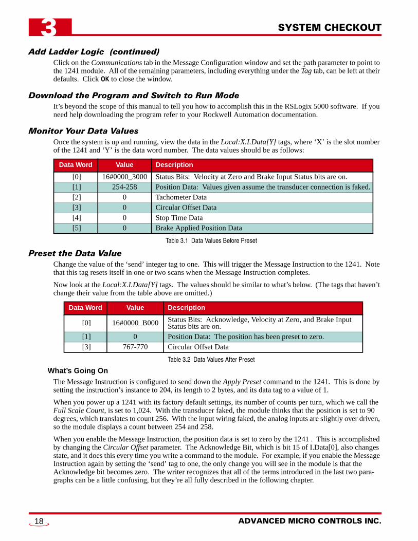
Monitor Your Data ValuesOnce the system is up and running, view the data in the Local:X.I.Data[Y] tags, where ‘X’ is the slot number of the 1241 and ‘Y’ is the data word number. The data values should be as follows:
Table 3.1 Data Values Before Preset
Preset the Data ValueChange the value of the ‘send’ integer tag to one. This will trigger the Message Instruction to the 1241. Note that this tag resets itself in one or two scans when the Message Instruction completes.
Now look at the Local:X.I.Data[Y] tags. The values should be similar to what’s below. (The tags that haven’t change their value from the table above are omitted.)
Table 3.2 Data Values After Preset
What’s Going OnThe Message Instruction is configured to send down the Apply Preset command to the 1241. This is done by setting the instruction’s instance to 204, its length to 2 bytes, and its data tag to a value of 1.
When you power up a 1241 with its factory default settings, its number of counts per turn, which we call the Full Scale Count, is set to 1,024. With the transducer faked, the module thinks that the position is set to 90 degrees, which translates to count 256. With the input wiring faked, the analog inputs are slightly over driven, so the module displays a count between 254 and 258.
When you enable the Message Instruction, the position data is set to zero by the 1241 . This is accomplished by changing the Circular Offset parameter. The Acknowledge Bit, which is bit 15 of I.Data[0], also changes state, and it does this every time you write a command to the module. For example, if you enable the Message Instruction again by setting the ‘send’ tag to one, the only change you will see in the module is that the Acknowledge bit becomes zero. The writer recognizes that all of the terms introduced in the last two para-graphs can be a little confusing, but they’re all fully described in the following chapter.
Data Word Value Description
[0] 16#0000_3000 Status Bits: Velocity at Zero and Brake Input Status bits are on.[1] 254-258 Position Data: Values given assume the transducer connection is faked.[2] 0 Tachometer Data[3] 0 Circular Offset Data[4] 0 Stop Time Data[5] 0 Brake Applied Position Data
Data Word Value Description
[0] 16#0000_B000 Status Bits: Acknowledge, Velocity at Zero, and Brake Input Status bits are on.
[1] 0 Position Data: The position has been preset to zero.[3] 767-770 Circular Offset Data
ADVANCED MICRO CONTROLS INC.18

20 Gear Drive, Plymouth IndTel: (860) 585-1254 Fax: (8
CHAPTER 4
SPECIFICATIONSModule LocationAny ControlLogix module slot. Occupies a sin-
gle slot.
Module TypeGeneric 1756 Module
Registers Used (32 bit DINT words)
All backplane programming from processor to 1241 is accomplished with RSLogix’s Mes-sage Instruction
Data Available to ProcessorTransducer Position, Velocity and Fault
Diagnostic data
Stop Time and Brake Applied Position avail-able when using Stop Time Monitor.
Min Rate Packet Interval (RPI) Time400 microseconds. Can be set to higher values.
Position TransducerDefault of AMCI brushless resolver transducer
Transducer Input Isolation1500 Vac through isolation transformers
Position ResolutionProgrammable to 1 part in 8,192
Position Update Time200 microseconds
Tachometer Resolution and Range1 RPM over 0 to 5,000 RPM range
Stop Time MonitorOn board timer measures the time between the
on off transition of the module’s DC Brake Input and the transducer rotation stopping.
Most commonly used in press applications to collect data to determine brake functionality, the module measures a stopping time of 34 milliseconds to 65.410 seconds with 1 milli-second resolution.
Programmable ParametersFull Scale Count (counts per turn)Preset ValueCount DirectionCircular OffsetLinear OffsetTachometer Update TimeTransducer Fault LatchTransducer TypeCOS Interrupt Enable
Program StorageEEPROM Memory
Minimum 100,000 write cycles
Brake Input10 to 30 Vdc isolated input. Requires 10 mA
minimum to operate.
DC Supply Voltage from BackplaneSerial #: 77364 and above:
0.540A max. @ 5Vdc
Serial #: Below 773640.250A max. @ 5Vdc nominal0.065A max. @ 24Vdc nominal0.250A max. @ 24Vdc under short circuit
conditions
Environmental ConditionsOperating Temperature: 0 to 60° C
Relative Humidity: 5 to 95%(w/o condensation)
Storage Temperature: -40 to 85°
This chapter contains the full specifications of the 1241. Included in it are mechanical, electrical, and environ-mental specifications of the unit as well as descriptions of the programmable parameters, their defaults and rangeof values. This chapter concludes with the specifications of other equipment used with the 1241 such as AMCItransducers and cabling.
Instance Qty
Input 100 6Output 195 1Config 1 0
. Park, Terryville, CT 0678660) 584-1973 http://www.amci.com
19

SPECIFICATIONS4
Functionality OverviewThe functionality of the 1241 is fairly easy to outline.
1) The 1241 supplies position and velocity feedback from a rotating shaft to a ControlLogix processor.
The position sensor is an AMCI brushless resolver.The position value is absolute, re-calculated every 200 microseconds, and is in no way dependent on the previous value.
If the shaft is rotated while power is removed from the 1241, the 1241 will be able to correctly determine the position of the shaft when power is re-applied. If a position value is incorrectly calculated due to a transient condition such as electrical noise, future position values will be correct once the transient condition ends.
2) The position value can be scaled to any value between 2 and 8,192 counts per turn. A scaling of 360 implies one count per degree of transducer shaft rotation.
3) The 1241 contains multiple parameters that allow you offset the position value.
These eliminate the need to mechanically align the transducer’s shaft with the machine’s shaft.
4) The 1241 contains a Count Direction parameter that allows you to program the direction of rotation needed to increase position values.
5) The velocity value is calculated as a change in position over time. This time can be set to 32 or 120 milliseconds. The velocity value is always scaled to revolutions per minute (RPM).
6) The 1241 has a Brake Input that can be used to monitor the stopping time of the transducer shaft.
This feature is typically used in press applications, but is applicably to any system that must moni-tor the stopping time of a load such as an overhead crane, mining cart, or an indexing table.The DC input triggers a brake measurement cycle when it makes an on off transition.The time from the deactivation of the input until the transducer motion stops is measured with one millisecond resolution.The position value where the input deactivated and the stopping time are reported to the processor.
The stop time monitor is a monitoring feature only. Any determination of the correct opera-tion of the press brake must be made by the system PLC through a user developed ladder logic program.
ADVANCED MICRO CONTROLS INC.20
SPECIFICATIONS 4
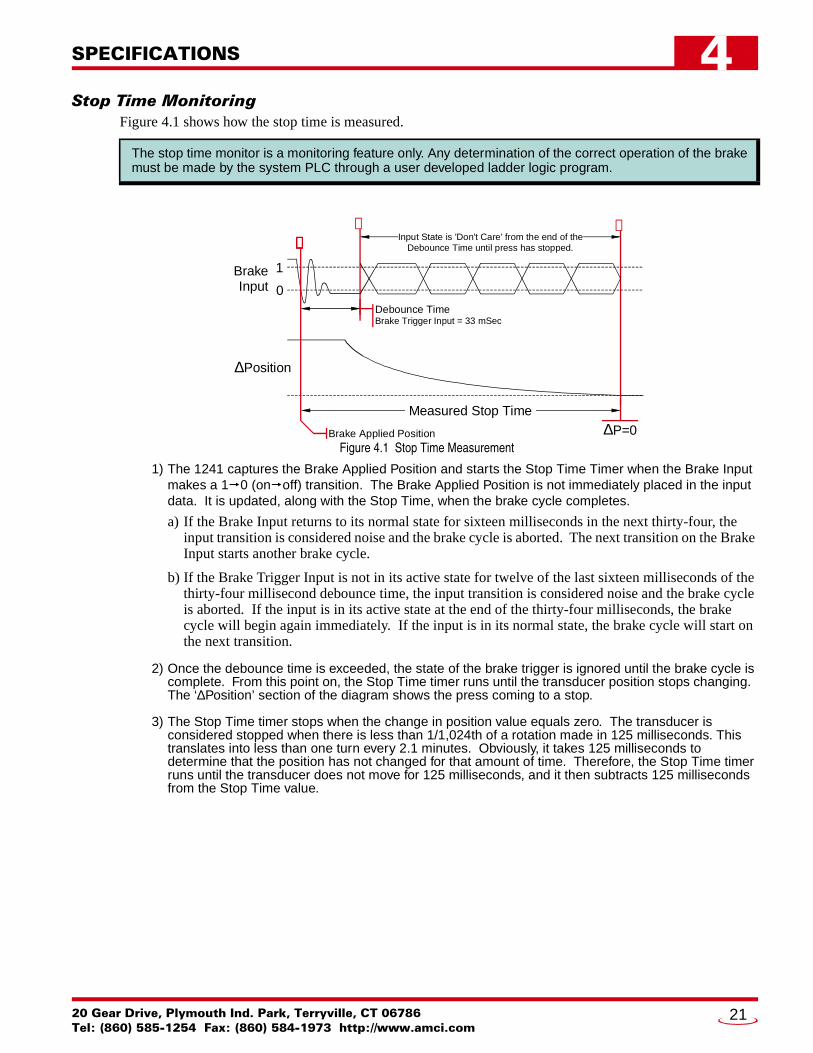
Stop Time MonitoringFigure 4.1 shows how the stop time is measured.
Figure 4.1 Stop Time Measurement
1) The 1241 captures the Brake Applied Position and starts the Stop Time Timer when the Brake Input makes a 1 0 (on off) transition. The Brake Applied Position is not immediately placed in the input data. It is updated, along with the Stop Time, when the brake cycle completes.
a) If the Brake Input returns to its normal state for sixteen milliseconds in the next thirty-four, the input transition is considered noise and the brake cycle is aborted. The next transition on the Brake Input starts another brake cycle.
b) If the Brake Trigger Input is not in its active state for twelve of the last sixteen milliseconds of the thirty-four millisecond debounce time, the input transition is considered noise and the brake cycle is aborted. If the input is in its active state at the end of the thirty-four milliseconds, the brake cycle will begin again immediately. If the input is in its normal state, the brake cycle will start on the next transition.
2) Once the debounce time is exceeded, the state of the brake trigger is ignored until the brake cycle is complete. From this point on, the Stop Time timer runs until the transducer position stops changing. The ‘∆Position’ section of the diagram shows the press coming to a stop.
3) The Stop Time timer stops when the change in position value equals zero. The transducer is considered stopped when there is less than 1/1,024th of a rotation made in 125 milliseconds. This translates into less than one turn every 2.1 minutes. Obviously, it takes 125 milliseconds to determine that the position has not changed for that amount of time. Therefore, the Stop Time timer runs until the transducer does not move for 125 milliseconds, and it then subtracts 125 milliseconds from the Stop Time value.
The stop time monitor is a monitoring feature only. Any determination of the correct operation of the brakemust be made by the system PLC through a user developed ladder logic program.
Debounce TimeBrake Trigger Input = 33 mSec
Measured Stop Time
Brake Applied Position
∆Position
∆P=0
Input State is 'Don't Care' from the end of theDebounce Time until press has stopped.
BrakeInput
1
0
➀➀➀➀➁ ➂
20 Gear Drive, Plymouth Ind. Park, Terryville, CT 06786Tel: (860) 585-1254 Fax: (860) 584-1973 http://www.amci.com
21

SPECIFICATIONS4
Hardware SpecificationsStatus LED’sThe two Status LED’s on the front panel allow you to quickly verify the operating status of the module. The OK LED tells you the status of the backplane communication. (It’s actually controlled by the A-B inter-face IC.) The STATUS LED give you information on the working state of the module itself.
OK LED: Solid Green – Module owned, two-way communication.
Blinking Green – PLC is in Program Mode or one-waycommunication. Module only send-ing data to the PLC.
Blinking Red – No communication between moduleand PLC.
STATUS LED: Solid Green – Module and transducer are OK.Blinking Green – Clearable transducer faultBlinking Red – Non-clearable transducer faultSolid Red – Module fault, such as no reference
voltage
Any problem with the module will cause the STATUS LED to turn on red. A problem with the transducer is indicated by blinking the LED. When it blinks green, the transducer signals were temporarily lost but the transducer is now working. This is most commonly caused by a loose connection or a burst of electrical noise. If the LED blinks red, the transducer is not sending back correct signals to the module.
The most common causes of a non-clearable transducer fault are:
Broken transducer cableNon-compatible transducerImproper wiring of the transducer cableImproper transducer cable installationFaulty transducerFaulty module
Transducer Input ConnectorFigure 4.3 shows the pinont of the Transducer Input Connector. The mating con-nector, AMCI part number MS-8P is not shown, but is included with the module. The figure also shows the resolver signals. Cabling specifications are given later in this chapter in the Transducer Cable Specification section starting on page 28. Wiring diagrams are given there and in Transducer Cable Installation section of chapter 6 starting on page 37.
R1/R2 – Reference Winding (Rotor)S1/S3 – COS Winding (Stator)S2/S4 – SIN Winding (Stator)
The mating connector is made by Phoenix Contact. Their part number is MC1,5/8-ST-3,81, with an order number of 1803633.
Figure 4.2 Front Panel Layout
Transducer Input
Connector
Brake LED
Status LED's
Brake Input Connector
RESOLVER
OK
STATUS
Figure 4.3 Transducer Input Connector
S3S1S4S2ShieldsShieldsR2R1
PIN 1
ADVANCED MICRO CONTROLS INC.22
SPECIFICATIONS 4
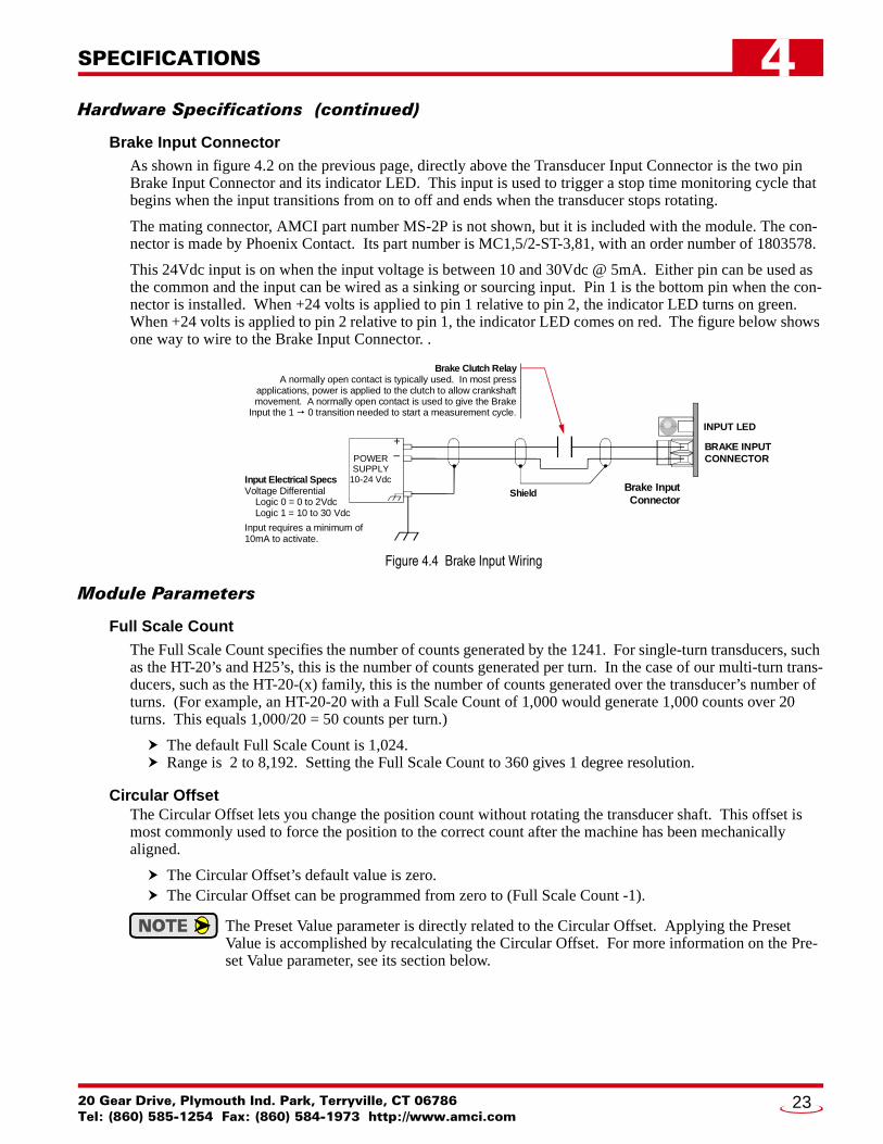
Hardware Specifications (continued)Brake Input ConnectorAs shown in figure 4.2 on the previous page, directly above the Transducer Input Connector is the two pin Brake Input Connector and its indicator LED. This input is used to trigger a stop time monitoring cycle that begins when the input transitions from on to off and ends when the transducer stops rotating.
The mating connector, AMCI part number MS-2P is not shown, but it is included with the module. The con-nector is made by Phoenix Contact. Its part number is MC1,5/2-ST-3,81, with an order number of 1803578.
This 24Vdc input is on when the input voltage is between 10 and 30Vdc @ 5mA. Either pin can be used as the common and the input can be wired as a sinking or sourcing input. Pin 1 is the bottom pin when the con-nector is installed. When +24 volts is applied to pin 1 relative to pin 2, the indicator LED turns on green. When +24 volts is applied to pin 2 relative to pin 1, the indicator LED comes on red. The figure below shows one way to wire to the Brake Input Connector. .
Figure 4.4 Brake Input Wiring
Module Parameters
Full Scale CountThe Full Scale Count specifies the number of counts generated by the 1241. For single-turn transducers, such as the HT-20’s and H25’s, this is the number of counts generated per turn. In the case of our multi-turn trans-ducers, such as the HT-20-(x) family, this is the number of counts generated over the transducer’s number of turns. (For example, an HT-20-20 with a Full Scale Count of 1,000 would generate 1,000 counts over 20 turns. This equals 1,000/20 = 50 counts per turn.)
The default Full Scale Count is 1,024. Range is 2 to 8,192. Setting the Full Scale Count to 360 gives 1 degree resolution.
Circular OffsetThe Circular Offset lets you change the position count without rotating the transducer shaft. This offset is most commonly used to force the position to the correct count after the machine has been mechanically aligned.
The Circular Offset’s default value is zero.The Circular Offset can be programmed from zero to (Full Scale Count -1).
The Preset Value parameter is directly related to the Circular Offset. Applying the Preset Value is accomplished by recalculating the Circular Offset. For more information on the Pre-set Value parameter, see its section below.
INPUT LED
BRAKE INPUTCONNECTOR
Brake Clutch RelayA normally open contact is typically used. In most press
applications, power is applied to the clutch to allow crankshaftmovement. A normally open contact is used to give the Brake
Input the 1 0 transition needed to start a measurement cycle.
Shield
+
POWERSUPPLY
10-24 VdcInput Electrical SpecsVoltage Differential Logic 0 = 0 to 2Vdc Logic 1 = 10 to 30 Vdc
Input requires a minimum of10mA to activate.
–
Brake InputConnector
20 Gear Drive, Plymouth Ind. Park, Terryville, CT 06786Tel: (860) 585-1254 Fax: (860) 584-1973 http://www.amci.com
23

SPECIFICATIONS4
Module Parameters (continued)Linear OffsetThe Linear Offset parameter changes the range of count values output by the unit and is used when the trans-ducer position directly correlates to a linear measurement that does not start at zero. One such example is an overhead crane. Another example is a press shut height measurement.
For example, a 1241 is used to measure a 50.00 inch span with 0.01 inch resolution. Therefore, the total number of counts over the full travel is: 50.00 inches / 0.01 inches/count = 5000 counts. The Full Scale Count parameter is then set to this value.
The 50 inches measured by the 1241 is in the range of 20.00 to 70.00 inches on the machine. You can use the Linear Offset to force the 1241 to send the position data to the processor in the correct format instead of using the processor to add an offset once the position value is in the data tag. The formula for the Linear Offset is:
Minimum Desired Value * Resolution = Linear Offset20.00 inches * 100 counts/inch = 2000 counts
The default Linear Offset is zero.The Linear Offset’s range is 0 to (32,768 – Full Scale Count).
Preset ValueThe Preset Value parameter allows you to set the value of the position data to any count value within its range. The range of the count values is (Linear Offset) to (Linear Offset + (Full Scale Count - 1)). When the Linear Offset equals zero, this translates into 0 to (Full Scale Count -1).
Programming the Preset Value does not change the position data, it only sets the value that the position will change to when an Apply Preset command is initiated.
The range of the Preset Value is (Linear Offset) to (Linear Offset + (Full Scale Count – 1)). When the Linear Offset equals zero, this reduces to 0 to (Full Scale Count – 1). If you program a Linear Offset and leave the Preset Value at zero, the 1241 will respond with an error.
COS Interrupt EnableThe COS (Change of State) Interrupt Enable parameter allows the 1241 to interrupt the processor whenever the position value changes. The processor should respond by reading the module’s data. These readings are in addition to the readings at the programmed Rate Packet Interval (RPI) Time. This is commonly used in programmable limit switch applications when the limits are being generated by the PLC.
Even though you will decrease the update time of the 1241, you will increase your overall scan time because the processor is forced to service the interrupts. In fact, do not enable this parameter if you are running at a high speed and/or high resolution. For example, setting the Scale Factor to 1000 and running the machine at 200 RPM will cause the 1241 to raise an COS interrupt every 300 microseconds.
Count DirectionThis parameter sets the direction of transducer shaft rotation that increases the position count. If the trans-ducer is wired as specified in this manual and the count direction is set to positive, the count will increase with clockwise rotation, (looking at the shaft). If the count direction is set to negative, the position count will increase with counter-clockwise rotation.
The default Count Direction Value is positive.
It is also possible to reverse the count direction by reversing wire pairs in the transducer cable. Once the machine is setup, you can easily change this parameter if the position is increasing in the wrong direction.
.581 inLinear Offset
70.00"
1.162 in50.00"
MeasureableSpan
20.00"
0.00"
Figure 4.5 Linear Offset Example
ADVANCED MICRO CONTROLS INC.24

SPECIFICATIONS 4
Module Parameters (continued)Tachometer ResponseThis parameter sets the time between tachometer updates. It only affects the update time of the tachometer. It does not affect the update time of the position value, which is always 200 microseconds.
The default Tachometer Response is 120 milliseconds.The Tachometer Response can be set to 120 or 32 milliseconds.
Transducer Fault LatchTransducer faults can be caused by improper wiring, electrical noise, or a damaged transducer. When the module detects a transducer fault, it sets an error flag in the data it transmits over the backplane. By default, the 1241 clears the fault message as soon as a working transducer is properly attached. It’s possible to latch transducer faults, which forces the 1241 to send the error flag until a Clear Errors command is received from the processor.
If you have a situation where electrical noise is causing spurious transducer faults that you can safely ignore, you can leave the Transducer Fault Latch disabled and force the 1241 to clear faults as soon as possible. Note that an intermittent wiring problem may also cause spurious faults. If you want to reliably capture these tran-sient faults, then you must enable the Transducer Fault Latch because the 1241 can detect and clear transducer faults much faster than the processor scans the module.
The default Transducer Fault Latch value is disabled.
Resolver TypeThe Resolver Type parameter makes most Autotech Controls single turn transducers compatible with the 1241 module.
The Resolver Type default value is AMCI.
Parameter Defaults and Ranges
Table 4.1 Factory Defaults and Ranges
Parameter Range Default
Full Scale Count 2 to 8,192 inclusive 1,024
Circular Offset 0 to (Full Scale Count – 1) 0
Linear Offset 0 to (32,768 – Full Scale Count) 0
Preset Value
(Linear Offset) to (Linear Offset + (Full Scale Count–1)) When the Linear Offset equals zero:
0 to (Full Scale Count – 1)
0
COS Interrupt Enable Disabled / Enabled Disabled
Count Direction Positive / Negative Positive
Tachometer Response 120 or 32 milliseconds 120 milliseconds
Transducer Fault Latch Disabled / Enabled Disabled
Resolver Type AMCI / Autotech AMCI
20 Gear Drive, Plymouth Ind. Park, Terryville, CT 06786Tel: (860) 585-1254 Fax: (860) 584-1973 http://www.amci.com
25
SPECIFICATIONS4
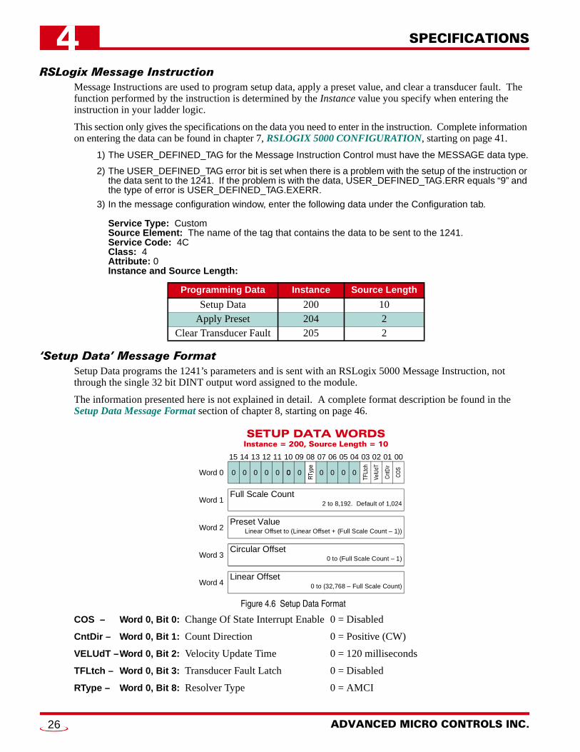
RSLogix Message InstructionMessage Instructions are used to program setup data, apply a preset value, and clear a transducer fault. The function performed by the instruction is determined by the Instance value you specify when entering the instruction in your ladder logic.
This section only gives the specifications on the data you need to enter in the instruction. Complete information on entering the data can be found in chapter 7, RSLOGIX 5000 CONFIGURATION, starting on page 41.
1) The USER_DEFINED_TAG for the Message Instruction Control must have the MESSAGE data type.
2) The USER_DEFINED_TAG error bit is set when there is a problem with the setup of the instruction or the data sent to the 1241. If the problem is with the data, USER_DEFINED_TAG.ERR equals “9” and the type of error is USER_DEFINED_TAG.EXERR.
3) In the message configuration window, enter the following data under the Configuration tab.
Service Type: CustomSource Element: The name of the tag that contains the data to be sent to the 1241.Service Code: 4CClass: 4Attribute: 0Instance and Source Length:
‘Setup Data’ Message FormatSetup Data programs the 1241’s parameters and is sent with an RSLogix 5000 Message Instruction, not through the single 32 bit DINT output word assigned to the module.
The information presented here is not explained in detail. A complete format description be found in the Setup Data Message Format section of chapter 8, starting on page 46.
Figure 4.6 Setup Data Format
COS – Word 0, Bit 0: Change Of State Interrupt Enable 0 = Disabled
CntDir – Word 0, Bit 1: Count Direction 0 = Positive (CW)
VELUdT –Word 0, Bit 2: Velocity Update Time 0 = 120 milliseconds
TFLtch – Word 0, Bit 3: Transducer Fault Latch 0 = Disabled
RType – Word 0, Bit 8: Resolver Type 0 = AMCI
Programming Data Instance Source Length
Setup Data 200 10Apply Preset 204 2
Clear Transducer Fault 205 2
SETUP DATA WORDSInstance = 200, Source Length = 10
15 14 13 12 11 10 09 08 07 06 05 04 03 02 01 00
Preset Value
Word 0
Word 1
Word 2
TFLt
ch
CO
S
RTy
pe
Cnt
Dir
VelU
dT
0
Linear Offset to (Linear Offset + (Full Scale Count – 1))
Full Scale Count2 to 8,192. Default of 1,024
000
Word 4
Word 3
000 0 0 0 0 0
Circular Offset0 to (Full Scale Count – 1)
Linear Offset0 to (32,768 – Full Scale Count)
ADVANCED MICRO CONTROLS INC.26

SPECIFICATIONS 4
‘Apply Preset’ Message FormatThis programming block applies the Preset Value programmed with the Setup Data programming block, caus-ing the Position value to become equal to the programmed Preset Value. This block is also sent with an RSLogix 5000 Message Instruction, not through the single 32 bit DINT output word assigned to the module.
The information presented here is not explained in detail. A complete format description can be found in the Apply Preset Message Format section of chapter 8, starting on page 47.
Figure 4.7 Apply Preset Format
AplyPST - Word 0, Bit 0: Apply Preset Value -This bit must be set when transmitting this message. Therefore, the value of the word must equal 1.
‘Clear Transducer Fault’ Message FormatThis programming block clears a latched transducer fault. This block is also sent with an RSLogix 5000 Mes-sage Instruction, not through the single 32 bit DINT output word assigned to the module.
The data word is not used with this command. Therefore, the state of the bits is “Don’t Care” and can be set to either zero or one. The module reads the Instance value of the command and clears the transducer fault if possible.
Figure 4.8 Clear Transducer Fault Format
Message Instruction Error CodesThe USER_DEFINED_TAG error bit is set when there is a problem with the setup of the instruction or the data sent to the 1241. If the problem is with the data, USER_DEFINED_TAG.ERR equals “9” and the type of error is USR_DEFINED_TAG.EXERR.
EXERR: ERROR DESCRIPTION
11) Any reserved bits are set to ‘1’2) Sending the “Apply Preset Value” message without bit 0 being set.3) Sending the “Apply Preset Value” message while there is a transducer fault.
2 Full Scale Count out of its range
3 Preset Value out of its range
4 Circular Offset out of its range
5 Linear Offset out of its range
APPLY PRESETInstance = 204, Source Length = 2
15 14 13 12 11 10 09 08 07 06 05 04 03 02 01 00
Word 0
AplyP
V
0000000 0 0 0 0 00 0 0 0
CLEAR TRANSDUCER FAULTInstance = 205, Source Length = 2
15 14 13 12 11 10 09 08 07 06 05 04 03 02 01 00
Word 0 1/01/01/01/01/01/01/01/01/01/01/01/01/01/01/01/0
20 Gear Drive, Plymouth Ind. Park, Terryville, CT 06786Tel: (860) 585-1254 Fax: (860) 584-1973 http://www.amci.com
27

SPECIFICATIONS4
Input Data FormatInput data is produced by the 1241 and is consumed by the processor. Note that all data is transmitted with 32 bit double integer (DINT) words. The information presented here is not explained in detail. A complete for-mat description can be found in the Input Data section of chapter 8, starting on page 45.
Figure 4.9 Input Data Words
ModErr - Word 0, Bit 0: Module Error
TransFlt - Word 0, Bit 1: Transducer Fault
BrakeIn - Word 0, Bit 12: Brake Input State. Set to ‘1’ when Brake Input is active. (Brake is active when it is not receiving power.)
Vel@0 - Word 0, Bit 13: Velocity at Zero.
ACK - Word 0, Bit 15: Acknowledge Bit. Set when a new message is received via a Message Instruction.
Transducer Cable SpecificationThe cable specified for use with the 1241 depends on the total length of the run.
For runs under 100 feet (30 meters), AMCI specifies Belden 9873 or an exact equivalent. Quabbin 6155 is an acceptable alternative.
For runs over 100 feet, AMCI specifies Belden 9730 or an exact equivalent. Quabbin 8606 is an accept-able alterative. These cables can be used for runs under 100 feet.
1) “Total length of run” refers to the distance from the transducer to the 1241. If you have four 26 foot lengths of cable that are spliced together to form a 104 foot total run, then each 26 foot cable must be Belden 9730 or equivalent.
2) The important characteristic when determining an acceptable equivalent is the capacitance between conductors. Belden 9873 has a conductor–conductor capacitance of 30 pf/ft. Belden 9730 has a conductor–conductor capacitance of 12.5 pf/ft.
The remainder of this chapter gives the specification of equipment that should be used with the 1241. Thisincludes specifications on transducer cabling, transducers, and resolvers.
INPUT DATA WORDS
15 14 13 12 11 10 09 08 07 06 05 04 03 02 01 00
ACK
Tachometer Data
I.Data[0]
I.Data[1]
I.Data[2]
I.Data[3]
I.Data[4]
I.Data[5]
Mod
Err
Brak
eIn
Vel@
0
Tran
sFlt
00
Position Data
Circular Offset
Stop Time
RESERVEDSet to Zero
31 – 16
0 to 5,000 max.
Brake Applied Position
0 to 8,191 max.†0 to (Full Scale Count – 1)†
0 to 8,191 max.0 to (Full Scale Count – 1)
34 to 65,410 milliseconds
0 to 8,191 max.0 to (Full Scale Count – 1)
0 0 0 0 0 0 000
Assuming a Linear Offset of zero. When the Linear Offset value is not zero, the Position Data will range from Linear Offset to (Linear Offset + (Full Scale Count - 1))In this case, the maximum position value is 32,767.
†
ADVANCED MICRO CONTROLS INC.28

SPECIFICATIONS 4
CTL-(x) SpecificationsIf you order a CTL-(x) cable from AMCI that is less than 100 feet long, we ship a cable that is made from Belden 9873 or equivalent. If you order a CTL-(x) that is over 100 feet, we ship a cable made from Belden 9730 or equivalent.
One end of the CTL-(x) has a Bendix MS connector that mates with all AMCI single turn transducers that have a connector†. The other end is pigtailed at the factory for easy connection to the MS-8P connector included with the 1241. The following is a wiring diagram from a CTL to the 1241’s MS-8P.
Figure 4.10 CTL-(x) Wiring Diagram
† HT-20C and HT-400 transducer are designed for conduit connections and do not have Bendix MS connectors. The H25-FL and H25-SL have integral cables instead of connectors. For these transducers, you can order bulk cable from AMCI.
CTLR-(x) SpecificationsCTLR-(x) cable is used with an HTT-20-1 transducer. The HTT-20-1 has two independent resolvers in one transducer package for applications that require redundant control systems. If you order a CTLR-(x) cable from AMCI that is less than 100 feet long, we ship a cable that is made from Belden 9873 or equivalent. If you order a CTL-(x) that is over 100 feet, we ship a cable made from Belden 9730 or equivalent.
One end of the CTLR-(x) has a Bendix MS connector that mates with the HTT-20-1 transducer†. The other ends are pigtailed at the factory for easy connection to the MS-8P connector included with the 1241 or the MS-8 connector used by most other AMCI modules. The following is a wiring diagram from a CTLR to the 1241’s MS-8P connectors.
Figure 4.11 CTLR-(x) Wiring Diagram
† The HTT-400-1 redundant resolver transducer has two separate connectors for the resolvers. For this trans-ducer, order two CTL-(x) cables.
BELDEN 9873 CableFor cable lengths greater than100' (30 meters) use BELDEN 9730.
Transducer Input ConnectorIncluded with Module.AMCI Part #: MS-8PPhoenix #: MSTB1,5/8-ST-3,81 18 03 63 3
TransducerConnectorAMCI Part #: MS-16Bendix #: MS3106A16S-1S
A B
C
DE
F G
BLK
WHT
GRN
BLK
SHIELDS
RED
87
6
5
4
3
2
1
S3S1S4S2Shields
R2
BLKR1
Shields
CTL-(x) CABLE
BLK
WHT
BLKGRN
SHIELDSREDBLK
S3
S2
ShieldsR2R1
A
N
B
C
D
EF
G
H
I
J
K
L
M
TransducerConnector AMCI Part #: MS-20Bendix #: MS3106A20-27S
BLK
WHT
BLKGRN
SHIELDSREDBLK
S3
S2
ShieldsR2R1
MODULEB
MODULEA
BELDEN 9873 Cable (2 Places)For cable lengths greater than100' (30 meters) use BELDEN 9730.
Transducer Input ConnectorIncluded with Module. (2 Places)AMCI Part #: MS-8PPhoenix #: MSTB1,5/8-ST-3,81 18 03 63 3
8
7
6
5
4
3
2
1
CTLR-(x) CABLE
8
7
6
5
4
3
2
1
S1S4
Shields
S1
S4
Shields
20 Gear Drive, Plymouth Ind. Park, Terryville, CT 06786Tel: (860) 585-1254 Fax: (860) 584-1973 http://www.amci.com
29

SPECIFICATIONS4
Transducer SpecificationsThe following table contains mechanical and environmental specifications for all of AMCI’s single-resolver transducers that are compatible with the 1241. Table 1.1, Compatible Transducers found on page 9 gives com-plete part numbers and descriptions of all compatible transducers.
Table 4.2 Single-Turn Transducer Specifications
Outline drawings of our transducers, and full spec sheets for our most popular models, are available on our website, www.amci.com. If you do not have internet access, contact AMCI and we’ll fax you the information.
Transducer Connector PinoutFigure 4.12 shows the connector pinout and internal resolver colors for all AMCI single transducers that have connectors. Note that some AMCI transducers have integral cables or conduit connections. For a complete listing of AMCI transducers without connectors, refer to Table 1.1, Compatible Transducers on page 9.
Specification All HT-20’sAll HT-20-(x),
HT-400, HTT-20-1,& HTT-400-1
All H25’s HT-6 All R11’s
Shaft Diameter 0.625" 0.625" 0.375" 0.188" 0.120" or 0.188"
Radial Shaft Loading 400 lbs. max. 400 lbs. max. 40 lbs. max. 8 lbs. max. 2 lbs. max.
Axial Shaft Loading 200 lbs. max. 200 lbs. max. 20 lbs. max. 4 lbs. max. 1 lb. max.
Starting Torque 8oz.-in@25°C 8oz.-in@25°C 1.5oz.-in@25°C 0.5oz.-in@25°C 0.1oz.-in@25°C
Moment of Inertia(oz.-in-sec.2) 6.25X10⁻⁴ 8.75X10⁻⁴ 6.00X10⁻⁴ 2.10X10⁻⁴ 0.51X10⁻⁴
Weight 4 lbs. 4 lbs. 1 lb. 0.7 lb. 0.25 lb.
Enclosure NEMA 4 or 4X NEMA 4 NEMA 4 NEMA 13 NEMA 1
Environmental (All Transducers)
Operating Temp-20 to 125°C
Shock50 G’s for 11 milliseconds
Vibration5 to 2000 Hz @ 20 G’s
S1: (RED)S3: (BLK)R1: (RED/WHT)R2: (BLK/WHT)S2: (YEL)S4: (BLU)
Figure 4.12 Transducer Connector Pinout
ADVANCED MICRO CONTROLS INC.30

20 Gear Drive, Plymouth IndTel: (860) 585-1254 Fax: (8
CHAPTER 5
GENERAL INSTALLATION GUIDELINESThis chapter is presented as a tool in the hopes of avoiding common installation prob-lems. It is not a substitute for the safety practices called out in local electrical codes or, in the United States, the National Electrical Code published by the National Fire Protec-tion Association. If any conflicts exist, local and national codes must be followed. It is the responsibility of the user to determine what installation practices must be followed in order to conform to all local and national codes.
BackgroundAMCI has extensively tested the 1241, both in the lab and in the field, under a wide range of conditions to see how the unit reacts to an adverse environment. This includes testing the unit after intentionally installing it incorrectly. The results of our testing is the following list of areas that must be addressed when engineering your system. The order of the list shows the areas that have the largest impact on system operation first.
1) Surge Suppression2) Grounding3) Wiring4) Power Supply Wattage and Filtering
This list also shows the first areas that should be investigated if your installation experiences problems.
Surge (EMI) Suppression
All inductive devices in the system, such as motors, motor starters, contactors, relays and sole-noids, must have surge suppression devices installed across their coils.
This includes all devices that share a power supply with the ControlLogix system, have wiring in the system’s enclosure, or wiring that is run in the same conduit as wiring connected to the 1241. DC loads are typically suppressed with a flyback diode, while AC loads are typically suppressed with a RC network or varistor.
RC Networks are the preferred suppressor for AC loads
This chapter gives general information on installing electronic controls in an industrial environ-ment including the importance of proper wiring, grounding, and surge suppression. If you areresponsible for installing the 1241, make sure you are familiar with these practices and followthem when installing the system.
. Park, Terryville, CT 0678660) 584-1973 http://www.amci.com
31

GENERAL INSTALLATION GUIDELINES5
Surge (EMI) Suppression (continued)The figure below show where surge suppression devices should be placed in the circuit.
Figure 5.1 Installing Surge Suppression Devices
Surge Suppression: DC OutputsAll inductive DC loads require a commutating, or “fly-back” diode across the load. Inductive DC loads include relays, solenoids, and DC motors.
Unlike resistors, diodes have a polarity and only conduct current in one direction. Therefore, care must be taken when installing diodes. As shown in the figure below, the cathode of the diode, which is denoted by the white or black band on one end of the diode, must be installed on the positive side of the load. If you install the diode backwards, it will most likely destroy itself as soon as you apply power to the load.
Figure 5.2 DC Output Surge Suppression
The diode must be sized to handle the inductive surge of the load when it turns off.
Some devices can be ordered with built in fly-back diodes, or the device manufacturer will offer sup-pressors designed specifically for the device. These types of devices are strongly recommended.
Suppressorn/o
InductiveDeviceContact
Power In
Power Return
Acceptable Connection
n/o
InductiveDeviceContact
Power In
Power Return
Un-Acceptable Connection 1
Suppressor
n/o
InductiveDeviceContact
Power In
Power Return
Un-Acceptable Connection 3
Suppressor
The acceptable connection supresses noise at its source. The wiring that connects the load to the power supply and contacts will not radiate noise when the load is switched and noise will not be coupled into the power supply.
This connection protects the power supply and contact, but allows noise to radiate through the load's wiring where it can be coupled into other cables around it, including the 1241's transducer cable.
n/o
InductiveDeviceContact
Power In
Power Return
Un-Acceptable Connection 2
Suppressor
This connection protects the power supply but nothing else. Noise can radiate through the load's wiring where it can be coupled into other cables around it and the contact may eventually be damaged by high voltage inductive spikes.
This connection protects the contact but nothing else. Noise can radiate through the load's wiring where it can be coupled into other cables or into the power supply. Noise in the supply may affect any device powered by it, including the Control-Logix system. Also, if the suppressor shorts out, the load will always receive power.
Diode
n/o
InductiveDeviceContact
Power In
Power Return
DC Load Connection+ –
COLORED BAND
ADVANCED MICRO CONTROLS INC.32

GENERAL INSTALLATION GUIDELINES 5
I/O Wiring (continued)Surge Suppression: AC OutputsIf you are switching AC loads with hard contacts such as mechanical relays, solenoids or contactors, then you must install a suppression network on the load switched by the relay. The two most common suppressors for AC loads are varistors and R-C networks.
AMCI strongly suggests R-C networks for all AC applications.
A varistor is a solid state device that turns on and conducts when the voltage across its terminals exceeds its rated value. Herein lies the problem with using a varistor as an AC suppressor. The voltage (problem) must be generated before the varistor responds. In our testing we have found that hard contacts will still arc when a varistor is placed across the AC load. This arcing is due to the fact that the breakdown voltage of the air between the contacts when they first open can be less than the rated voltage of the varistor. If the instanta-neous AC voltage applied to the contacts is above the breakdown voltage of air, but less than the rated voltage of the varistor, the contacts will arc.
On the other hand, an R-C network acts as a low-pass filter, instantaneously dampening fast transients when they occur. The main drawback of R-C networks is that they are harder to correctly specify than varistors. Varistors only require you to specify breakdown voltage and power dissipation ratings. R-C networks require you to balance the need of suppression when the contacts open against the amount of surge current the relay can tolerate when the contacts close. Table 5.1 shows the trade-offs you must be aware of when specifying R-C networks.
Table 5.1 R-C Network Trade-offs
In general, capacitor values range from 0.1 to 1.0 µF and resistor values range from 150 to 680 ohms.
The easiest way to specify a R-C network is by following the recommendations of the load’s manufacturer. Most manufacturers have tested and specify standard R-C networks, and many sell networks that are designed to integrate with their products. If you cannot get help from your load’s manufacturer, feel free to contact AMCI for assistance.
When Contacts Close When Contacts Open
Low Resistance, High Capacitance
Higher surge current through relay contacts to charge capacitor. (Negative) Lower transient voltage spike. (Positive)
High Resistance, Low Capacitance
Lower surge current through relay contacts to charge capacitor. (Positive) Higher transient voltage spike. (Negative)
20 Gear Drive, Plymouth Ind. Park, Terryville, CT 06786Tel: (860) 585-1254 Fax: (860) 584-1973 http://www.amci.com
33

GENERAL INSTALLATION GUIDELINES5
GroundingProper grounding is the single most important consideration for a safe installation. Proper grounding also ensures that unwanted electrical currents, such as those induced by electromagnetic noise, will be quickly shunted to ground instead of flowing through the machine.
AMCI strongly suggests the use of a ground bus in the enclosure that houses the 1241. As shown in figure 5.3, the ground bus becomes the central grounding point for the enclosure and its equipment. Bonding wires are run from the enclosure and each piece of equipment to the ground bus, and then a single grounding elec-trode conductor is run directly to the system’s grounding electrode.
Each connection must be separate, so a ground bus is typically fabricated in-house or by the panel shop responsible for wiring the enclosure.
All ground connections must be permanent and continuous to provide a low-impedance path to earth ground for induced noise currents. The ControlLogix chassis must be connected to earth ground through its mounting in the enclosure, and with a grounding wire connected to the grounding stud on the bottom of the ControlLogix chassis. Any non-isolated power supply attached to the ControlLogix system must be connected to the same earth ground as the chas-sis to avoid ground loops. All isolation transformer secondary windings that are grounded to conform to local or national codes must be grounded to the same earth ground as the machine ground.
WiringThe most important aspect of wiring is determining the amount of voltage and power carried by the cable and separating low power cabling from high power cabling. Inside of an enclosure, separate the two types of cabling with as much physical distance as possible and keep the wiring neat. Outside of the enclosure, low and high power cabling must be run in separate conduits.
Transducer Cabling (Low Power)
1) Transducer signals are of low voltage and low power. If you are using A-B guidelines for cabling installation, treat the transducer cable as a Category 2 cable. Transducer cable can be installed in conduit along with other low power cabling such as communication cables and low power ac/dc I/O lines. It cannot be installed in conduit with ac power lines or high power ac/dc I/O lines.
2) The shield of the cable must be grounded at the 1241 only. If you must splice the transducer cable, it must be done in a grounded junction box. When splicing, treat the shield as a signal-carrying conductor. Do not connect the shield to earth ground at the junction box or transducer. If your transducer cable has individually shielded pairs, then ideally the shields in the cable are also kept isolated from each other in the junction box as well.
Figure 5.3 Ground Bus System
GROUND BUSInternal to Enclosure
Central Grounding Point forEnclosure and ALL of its Equipment.
ControlLogix SystemMounted to Back Panel.
EQUIPMENT ENCLOSURE
GRO
UN
DIN
GELE
CTRO
DE
SYSTEM
RESOLVER
OK
STATUS
Logix5550
BAT
RUN
RUN RE M PROG
OK
RS232
I/O
DC OUTPUT
ST
ST
ST
ST
DC OUTPUT
ST
ST
ST
ST
Figure 5.4 Typical Enclosure
LOW POWER CONDUITTransducer Cable and Input Sensor Cabling
HIGH POWER CONDUITAC/DC Output and Power Cabling
GROUND BUSInternal to Enclosure
Central Grounding Point for allEquipment in Enclosure.
ControlLogix SystemMounted to Back Panel.
EQUIPMENT ENCLOSURE
RESOLVER
OK
S TATUS
Logix5550
BAT
RUN
RUN REM PROG
OK
RS 232
I/O
DC OUTPUT
ST
ST
ST
ST
DC OUTPUT
ST
ST
ST
ST
ADVANCED MICRO CONTROLS INC.34

GENERAL INSTALLATION GUIDELINES 5
Wiring (continued)Input Cabling (Low Power DC & AC)
1) Cabling from low power DC sensors or relays, typically tied to PLC input cards or the Brake Input of the 1241, must be shielded. Follow the two guidelines given above for Transducer Cabling. DC Input cabling and the transducer cable can be installed in the same conduit.
2) Depending on local codes, cabling from low power AC sensors or relays may or may not be installed with cabling from DC sensors. Follow the two guidelines given above for Transducer Cabling. Cabling for AC sensors, must, without exception, be shielded.
Output Wiring (High Power AC & DC)
1) Output Wiring must be kept separate from the transducer and input wiring in order to lessen the possibility of coupling transient noise into the low power cabling.
2) If a conduit containing the transducer cable or input wiring must cross conduit that contains Output Wiring, they must cross at right angles.
Power Supply Wiring (24Vdc)
1) If you have a separate DC supply for the ControlLogix system, then it is most likely a small one that is mounted in the enclosure with the system. In this case, AC power for the supply can be routed with output wiring. AC power should never be routed with the transducer or input cabling.
2) If you are using a system supply and it’s outside the enclosure, then the supply lines should be run with the output lines if local codes permit.
Other Power Wiring (High Power AC & DC)1) Power Wiring must be kept separate from the transducer and input wiring in order to lessen the
possibility of coupling transient noise into the low power cabling.
2) If a conduit containing the transducer cable or input wiring must cross conduit that contains Power Wiring, they must cross at right angles.
3) Whenever possible, conduit that contains transducer or input cabling must be kept 1 foot (30 cm) away from 120Vac conductors, 2 feet (61 cm) from 240Vac conductors, and 3 feet (91 cm) from 480+ Vac conductors.
Power Supply Wattage and FilteringA properly sized power supply is vital to system operation. The best guideline that we can give you is to buy the best supply your budget allows.
When sizing system supplies, take into consideration the surge requirements of the components you are attaching to the supply. Most devices draw a “surge” current for a brief time when they power up. If your supply cannot accommodate these surge currents, the output voltage may momentarily drop when a device turns on, causing data errors.
The other thing to consider when choosing a supply is output filtering. The better the supply’s filtering, the better it can absorb noise that may be induced into the power supply wiring.
20 Gear Drive, Plymouth Ind. Park, Terryville, CT 06786Tel: (860) 585-1254 Fax: (860) 584-1973 http://www.amci.com
35

GENERAL INSTALLATION GUIDELINES5
NotesADVANCED MICRO CONTROLS INC.36

20 Gear Drive, Plymouth IndTel: (860) 585-1254 Fax: (8
CHAPTER 6
INSTALLING THE 1241This chapter is not a substitute for the safety practices called out in local electrical codes or, in the United States, the National Electrical Code published by the National Fire Pro-tection Association. If any conflicts exist, local and national codes must be followed. It is the responsibility of the user to determine what installation practices must be followed to conform to all local and national codes.
Installing the ModuleThe 1241 can be installed in any ControlLogix module slot as long as power supply requirements are met. The table below shows the current requirements of the modules. A change was made to the power require-ments starting with serial number 77364, which was shipped December 20, 2002. All units shipped from AMCI after this date use the 5Vdc supply only.
† SC = Short Circuit condition. This value occurs if there is a short placed across the refer-ence voltage pins, which are pins 1 and 2 of the eight pin Transducer Input Connector.
1) Align the module’s circuit board with the top and bottom card guides in the rack.
2) Gently slide the module into the rack until the top and bottom latches secure the module in place.
To remove the module, depress the top and bottom latches and slide the module out of the rack.
The ControlLogix backplane is hot-swappable, however, Rockwell Automation discovered a problem with hot-swapping modules that use the 24Vdc supply. All 1241’s with a serial num-ber of 77364 or above can be installed and removed while power is applied to the chassis. Rockwell Automation’s guidelines for installing and removing modules under power must be followed to insure safe operation. If you have a module with a serial number below 77364 and you need the hot-swap capability, contact AMCI for assistance.
Transducer Cable InstallationPre-assembled and tested CTL-(X) and CTLR-(x) cables are available from AMCI. They come with the transducer connector soldered and assembled on the cable and the module connections dressed and ready for connection to the 1241’s Transducer Input Connector, which is included with the module. Cable specifica-tions can be found under CTL-(x) Specifications on page 29.
1) Resolvers are low voltage, low power devices. If you are using A-B guidelines for cabling installation, treat the transducer cable as a Category 2 cable. It can be installed in conduit along with other low power cabling such as communication cables and low power ac/dc I/O lines. It cannot be installed in conduit with ac power lines or high power ac/dc I/O lines.
This chapter gives installation information specific to the 1241, its transducer, and its brake input.The chapter assumes you are familiar with installing electronic controls in an industrial environ-ment including the importance of proper wiring, grounding, and surge suppression. If you areresponsible for installing the 1241, make sure you are familiar with these practices and followthem when installing the system. The previous chapter, which starts on page 31, give generalguidelines you should follow when installing the 1241.
Backplane Supply Serial 77364+ Serial <77364
5Vdc 0.540A (2.70W) 0.250A (1.25W)
24Vdc (nominal) 0A 0.065A (1.56W)
24Vdc (SC† condition) 0A 0.250A (6.00W)
. Park, Terryville, CT 0678660) 584-1973 http://www.amci.com
37

INSTALLING THE 12416
2) The shields of the transducer cable must be grounded at the 1241 module only! Grounding isaccomplished through the module. (The Shield pins on the Transducer Input Connector is brought to the ControlLogix chassis.) When installing the cable, treat the shield as a signal carrying conductor. Do not connect the shield to ground at any junction box or the transducer. This will eliminate ground loops that could damage the module or ControlLogix system.
CTL-(x) Wiring Diagram
Figure 6.1 CTL-(x) Wiring Diagram
CTLR-(x) Wiring DiagramThe CTLR-(x) is used to attach a HTT-20-1 redundant transducer to two 1241 modules. The HTT-400-1 has a separate connector for each resolver and uses two standard CTL-(x) cables.
Figure 6.2 CTLR-(x) Wiring Diagram
BELDEN 9873 CableFor cable lengths greater than100' (30 meters) use BELDEN 9730.
Transducer Input ConnectorIncluded with Module.AMCI Part #: MS-8PPhoenix #: MSTB1,5/8-ST-3,81 18 03 63 3
TransducerConnectorAMCI Part #: MS-16Bendix #: MS3106A16S-1S
A B
C
DE
F G
BLK
WHT
GRN
BLK
SHIELDS
RED
8
7
6
5
4
3
2
1
S3S1S4S2Shields
R2
BLKR1
Shields
CTL-(x) CABLE
BLK
WHT
BLKGRN
SHIELDSREDBLK
S3
S2
ShieldsR2R1
A
N
B
C
D
EF
G
H
I
J
K
L
M
TransducerConnector AMCI Part #: MS-20Bendix #: MS3106A20-27S
BLK
WHT
BLKGRN
SHIELDSREDBLK
S3
S2
ShieldsR2R1
MODULEB
MODULEA
BELDEN 9873 Cable (2 Places)For cable lengths greater than100' (30 meters) use BELDEN 9730.
Transducer Input ConnectorIncluded with Module. (2 Places)AMCI Part #: MS-8PPhoenix #: MSTB1,5/8-ST-3,81 18 03 63 3
8
7
6
5
4
3
2
1
CTLR-(x) CABLE
8
7
6
5
4
3
2
1
S1S4
Shields
S1
S4
Shields
ADVANCED MICRO CONTROLS INC.38

INSTALLING THE 1241 6
Transducer InstallationTransducer Outline DrawingsAMCI offers a broad line of resolver based transducers for use with the 1241 module. (See Compatible Transducers on page 9.) Outline drawings for all of these transducers, and full spec sheets for our most pop-ular transducers, are available on our website, www.amci.com. If you do not have internet access, contact AMCI and we will fax the information to you.
Transducer MountingAll AMCI resolver based transducers are designed to operate in the industrial environment and therefore require little attention. However, there are some general guidelines that should be observed to ensure long life.
Limit transducer shaft loading to the following maximums:
Table 6.1 Transducer Bearing Loads
Minimize shaft misalignment when direct coupling shafts. Even small misalignments produce large loading effects on front bearings. It is recommended that you use a flexible coupler whenever possible. A flexible coupler is required for all HT-6 transducers and R11 resolvers.
Autotech TransducersMost single turn transducer resolvers from Autotech Controls can be made compatible with the 1241 through the use of the Resolver Type parameter. An AMCI RM-3 Reference module is not required. Further informa-tion on using Autotech transducer can be found in the FAQ section of our website, www.amci.com. The FAQ is entitled “Can I Use Transducer From Other Manufacturers With AMCI Controllers?”.
Brake Input WiringIf you are using the 1241 in a press control application, or any application that requires you to measure the stopping time of a load once a brake is applied, you can use the stop time monitor of the unit. See Stop Time Monitoring on page 21 for information on how the stop time monitor works. If your application does not have this requirement, you can disable the stop time monitor by not wiring the Brake Input.
Input ConnectorFigure 6.3 shows a simplified schematic of the Brake Input. Note that the input requires 10 - 30 Vdc at 10 mA to operate. The circuit is completely isolated, so it can be wired as a sinking or sourcing input as shown in figure 6.4 on the following page.
Figure 6.3 Brake Input Schematic
Radial Load Axial Load
All 0.625" Shafts 100 lbs. (445 N) 50 lbs. (222 N)
All 0.375" & 10mm Shafts 30 lbs. (133 N) 15 lbs. (66.7 N)
All Other Shafts 1 lb. (4.45 N) 0.5 lb. (2.22 N)
INPUT LED
BRAKE INPUTCONNECTOR
Optocoupler
Input LED
RED
GREEN
20 Gear Drive, Plymouth Ind. Park, Terryville, CT 06786Tel: (860) 585-1254 Fax: (860) 584-1973 http://www.amci.com
39

INSTALLING THE 12416
Brake Input Wiring (continued)Connector WiringFigure 6.4 below is an example of how to wire the Brake Input. The figure assumes that a relay is used to trig-ger it. A normally open contact is shown because an on-to-off (1 0) transition is needed to trigger the stop time monitoring cycle. In typical press control configurations, power must be applied to the brake clutch before the crankshaft can rotate. In this case, the normally open contact is closed and power is applied to the input. When power is removed from the clutch to apply the brake, the contact opens and the unit sees the on-to-off transition needed to start the stop time monitoring cycle.
Shielded cable should be used to help with signal noise immunity. Treat the shield as a signal carrying conductor and ground it only at the power supply or the 1241. Do not ground the shield at any junction box or at both the power supply and unit. This will help eliminate poten-tial ground loops in your system.
Figure 6.4 Brake Input Wiring
INPUT LED
BRAKE INPUTCONNECTOR
Brake Clutch RelayA normally open contact is typically used. In most press
applications, power is applied to the clutch to allow crankshaftmovement. A normally open contact is used to give the Brake
Input the 1 0 transition needed to start a measurement cycle.
Shield
+
POWERSUPPLY
10-24 VdcInput Electrical SpecsVoltage Differential Logic 0 = 0 to 2Vdc Logic 1 = 10 to 30 Vdc
Input requires a minimum of10mA to activate.
–
Brake InputConnector
ADVANCED MICRO CONTROLS INC.40

20 Gear Drive, Plymouth IndTel: (860) 585-1254 Fax: (8
CHAPTER 7
RSLOGIX 5000 CONFIGURATIONA Word About Message InstructionsMessage Instructions are used to program the 1241 instead of the output words assigned to the module. AMCI decided on this because the Message Instruction has built in hand shaking and error codes so you don’t have to create this with your ladder logic. The Message Instruction also has Extended Error Codes, which the 1241 uses to tell the processor when there is an error in the data sent to it. Extended Error Codes are given in the Error Checking section of the Sample Program chapter, starting on page 51.
STEP 1: Open Your ProjectOnce you’ve started RSLogix 5000, open and existing project or create a new one.
STEP 2: Configure the 1241’s Slot2.1) Right click on the I/O Configuration branch in the open project tree window and select New Module...2.2) Select 1756-MODULE as the module type. The description field will change to “Generic 1756 Module”.2.3) Click OK. The Module Properties window will open and it will look similar to figure 7.1 below.
Figure 7.1 Module Properties Window
Enter the following data into the page:Name: Your choice, but it must begin with a letter.Description: Your choice.Comm Format: Data - DINTSlot: Location of 1241 module.Connection Parameters:
This chapter covers how to add a 1241 to a ControlLogix project. It covers how to configure the1241’s slot, how to add data and controller tags, and how to add a Message Instruction to yourladder logic. The next chapter covers the format of the data you will read and write to the module.
This chapter was written using RSLogix 5000, Standard Edition, Version 10.0.0. If you are notrunning this version, your setup may differ slightly. Refer to your Rockwell Software documenta-tion if you have any questions.
Assembly Instance SizeInput: 100 6
Output: 195 1Configuration: 1 0
. Park, Terryville, CT 0678660) 584-1973 http://www.amci.com
41
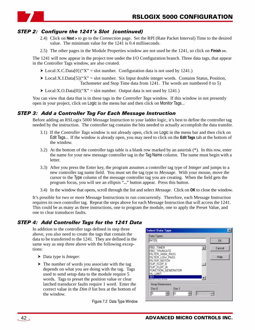
RSLOGIX 5000 CONFIGURATION7
STEP 2: Configure the 1241’s Slot (continued)2.4) Click on Next > to go to the Connection page. Set the RPI (Rate Packet Interval) Time to the desired value. The minimum value for the 1241 is 0.4 milliseconds.
2.5) The other pages in the Module Properties window are not used be the 1241, so click on Finish >>.
The 1241 will now appear in the project tree under the I/O Configuration branch. Three data tags, that appear in the Controller Tags window, are also created.
Local:X.C.Data[0] (“X” = slot number. Configuration data is not used by 1241.)
Local:X.I.Data[5](“X” = slot number. Six Input double integer words. Contains Status, Position,Tachometer and Stop Time data from 1241. The words are numbered 0 to 5)
Local:X.O.Data[0](“X” = slot number. Output data is not used by 1241.)
You can view that data that is in these tags in the Controller Tags window. If this window in not presently open in your project, click on Logic in the menu bar and then click on Monitor Tags...
STEP 3: Add a Controller Tag For Each Message InstructionBefore adding an RSLogix 5000 Message Instruction to your ladder logic, it’s best to define the controller tag needed by the instruction. The controller tag contains the bits needed to actually accomplish the data transfer.
3.1) If the Controller Tags window is not already open, click on Logic in the menu bar and then click on Edit Tags... If the window is already open, you may need to click on the Edit Tags tab at the bottom of the window.
3.2) At the bottom of the controller tags table is a blank row marked by an asterisk (*). In this row, enter the name for your new message controller tag in the Tag Name column. The name must begin with a letter.
3.3) After you press the Enter key, the program assumes a controller tag type of Integer and jumps to a new controller tag name field. You must set the tag type to Message. With your mouse, move the cursor to the Type column of the message controller tag you are creating. When the field gets the program focus, you will see an ellipsis “...” button appear. Press this button.
3.4) In the window that opens, scroll through the list and select Message. Click on OK to close the window.
It’s possible for two or more Message Instructions to run concurrently. Therefore, each Message Instruction requires its own controller tag. Repeat the steps above for each Message Instruction that will access the 1241. This could be as many as three instructions, one to program the module, one to apply the Preset Value, and one to clear transducer faults.
STEP 4: Add Controller Tags for the 1241 DataIn addition to the controller tags defined in step three above, you also need to create the tags that contain the data to be transferred to the 1241. They are defined in the same way as step three above with the following excep-tions:
Data type is Integer.
The number of words you associate with the tag depends on what you are doing with the tag. Tags used to send setup data to the module require 5 words. Tags to preset the position value or clear latched transducer faults require 1 word. Enter the correct value in the Dim 0 list box at the bottom of the window.
Figure 7.2 Data Type Window
ADVANCED MICRO CONTROLS INC.42
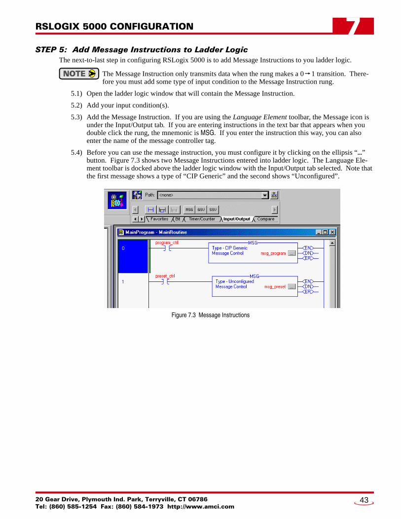
RSLOGIX 5000 CONFIGURATION 7
STEP 5: Add Message Instructions to Ladder LogicThe next-to-last step in configuring RSLogix 5000 is to add Message Instructions to you ladder logic.
The Message Instruction only transmits data when the rung makes a 0 1 transition. There-fore you must add some type of input condition to the Message Instruction rung.
5.1) Open the ladder logic window that will contain the Message Instruction.
5.2) Add your input condition(s).
5.3) Add the Message Instruction. If you are using the Language Element toolbar, the Message icon is under the Input/Output tab. If you are entering instructions in the text bar that appears when you double click the rung, the mnemonic is MSG. If you enter the instruction this way, you can also enter the name of the message controller tag.
5.4) Before you can use the message instruction, you must configure it by clicking on the ellipsis “...” button. Figure 7.3 shows two Message Instructions entered into ladder logic. The Language Ele-ment toolbar is docked above the ladder logic window with the Input/Output tab selected. Note that the first message shows a type of “CIP Generic” and the second shows “Unconfigured”.
Figure 7.3 Message Instructions
20 Gear Drive, Plymouth Ind. Park, Terryville, CT 06786Tel: (860) 585-1254 Fax: (860) 584-1973 http://www.amci.com
43
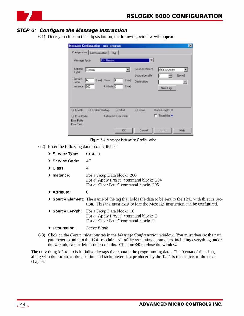
RSLOGIX 5000 CONFIGURATION7
STEP 6: Configure the Message Instruction6.1) Once you click on the ellipsis button, the following window will appear.
Figure 7.4 Message Instruction Configuration
6.2) Enter the following data into the fields:
Service Type: Custom
Service Code: 4C
Class: 4
Instance: For a Setup Data block: 200For a “Apply Preset” command block: 204For a “Clear Fault” command block: 205
Attribute: 0
Source Element: The name of the tag that holds the data to be sent to the 1241 with this instruc-tion. This tag must exist before the Message instruction can be configured.
Source Length: For a Setup Data block: 10For a “Apply Preset” command block: 2For a “Clear Fault” command block: 2
Destination: Leave Blank
6.3) Click on the Communications tab in the Message Configuration window. You must then set the path parameter to point to the 1241 module. All of the remaining parameters, including everything under the Tag tab, can be left at their defaults. Click on OK to close the window.
The only thing left to do is initialize the tags that contain the programming data. The format of this data, along with the format of the position and tachometer data produced by the 1241 is the subject of the next chapter.
ADVANCED MICRO CONTROLS INC.44
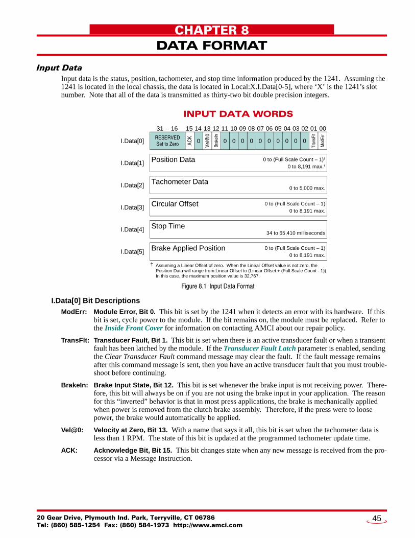
20 Gear Drive, Plymouth IndTel: (860) 585-1254 Fax: (8
CHAPTER 8
DATA FORMATInput DataInput data is the status, position, tachometer, and stop time information produced by the 1241. Assuming the 1241 is located in the local chassis, the data is located in Local:X.I.Data[0-5], where ‘X’ is the 1241’s slot number. Note that all of the data is transmitted as thirty-two bit double precision integers.
Figure 8.1 Input Data Format
I.Data[0] Bit DescriptionsModErr: Module Error, Bit 0. This bit is set by the 1241 when it detects an error with its hardware. If this
bit is set, cycle power to the module. If the bit remains on, the module must be replaced. Refer to the Inside Front Cover for information on contacting AMCI about our repair policy.
TransFlt: Transducer Fault, Bit 1. This bit is set when there is an active transducer fault or when a transient fault has been latched by the module. If the Transducer Fault Latch parameter is enabled, sending the Clear Transducer Fault command message may clear the fault. If the fault message remains after this command message is sent, then you have an active transducer fault that you must trouble-shoot before continuing.
BrakeIn: Brake Input State, Bit 12. This bit is set whenever the brake input is not receiving power. There-fore, this bit will always be on if you are not using the brake input in your application. The reason for this “inverted” behavior is that in most press applications, the brake is mechanically applied when power is removed from the clutch brake assembly. Therefore, if the press were to loose power, the brake would automatically be applied.
Vel@0: Velocity at Zero, Bit 13. With a name that says it all, this bit is set when the tachometer data is less than 1 RPM. The state of this bit is updated at the programmed tachometer update time.
ACK: Acknowledge Bit, Bit 15. This bit changes state when any new message is received from the pro-cessor via a Message Instruction.
INPUT DATA WORDS
15 14 13 12 11 10 09 08 07 06 05 04 03 02 01 00
ACK
Tachometer Data
I.Data[0]
I.Data[1]
I.Data[2]
I.Data[3]
I.Data[4]
I.Data[5]
Mod
Err
Brak
eIn
Vel@
0
Tran
sFlt
00
Position Data
Circular Offset
Stop Time
RESERVEDSet to Zero
31 – 16
0 to 5,000 max.
Brake Applied Position
0 to 8,191 max.†0 to (Full Scale Count – 1)†
0 to 8,191 max.0 to (Full Scale Count – 1)
34 to 65,410 milliseconds
0 to 8,191 max.0 to (Full Scale Count – 1)
0 0 0 0 0 0 000
Assuming a Linear Offset of zero. When the Linear Offset value is not zero, the Position Data will range from Linear Offset to (Linear Offset + (Full Scale Count - 1))In this case, the maximum position value is 32,767.
†
. Park, Terryville, CT 0678660) 584-1973 http://www.amci.com
45
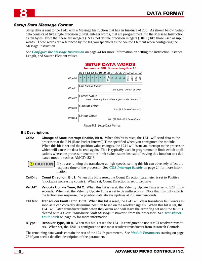
DATA FORMAT8
Setup Data Message FormatSetup data is sent to the 1241 with a Message Instruction that has an Instance of 200. As shown below, Setup data consists of five single precision (16 bit) integer words, that are programmed into the Message Instruction as ten bytes. Note that these are integers (INT), not double precision integers (DINT) like those used as input words. These words are referenced by the tag you specified as the Source Element when configuring the Message Instruction.
See Configure the Message Instruction on page 44 for more information on setting the instruction Instance, Length, and Source Element values.
Figure 8.2 Setup Data Format
Bit DescriptionsCOS: Change of State Interrupt Enable, Bit 0. When this bit is reset, the 1241 will send data to the
processor at the RPI (Rate Packet Interval) Time specified when you configured the module. When this bit is set and the position value changes, the 1241 will issue an interrupt to the processor which will cause the data be read again. This is typically used in programmable limit switch appli-cations where the processor determines limit switch states instead of leaving this function to a ded-icated module such as AMCI’s 8213.
If you are running the transducer at high speeds, setting this bit can adversely affect the response time of the processor. See COS Interrupt Enable on page 24 for more infor-mation.
CntDir: Count Direction, Bit 1. When this bit is reset, the Count Direction parameter is set to Positive (clockwise increasing counts). When set, Count Direction is set to negative.
VelUdT: Velocity Update Time, Bit 2. When this bit is reset, the Velocity Update Time is set to 120 milli-seconds. When set, the Velocity Update Time is set to 32 milliseconds. Note that this only affects the tachometer response, the position data always updates at 200 microseconds.
TFLtch: Transducer Fault Latch, Bit 3. When this bit is reset, the 1241 will clear transducer fault errors as soon as it can correctly determine position based on the resolver signals. When this bit is set, the 1241 will latch transducer faults when they occur and will leave the error flag set until the fault is cleared with a Clear Transducer Fault Message Instruction from the processor. See Transducer Fault Latch on page 25 for more information.
RType: Resolver Type, Bit 8. When this bit is reset, the 1241 is configured to use AMCI resolver transdu-crs. When set, the 1241 is configured to use most resolver transducers from Autotech Controls.
The remaining data words contain the rest of the 1241’s parameters. See Module Parameters starting on page 23 if you need a detailed description of the parameters.
SETUP DATA WORDSInstance = 200, Source Length = 10
15 14 13 12 11 10 09 08 07 06 05 04 03 02 01 00
Preset Value
Word 0
Word 1
Word 2
TFLt
ch
CO
S
RTy
pe
Cnt
Dir
VelU
dT
0
Linear Offset to (Linear Offset + (Full Scale Count – 1))
Full Scale Count2 to 8,192. Default of 1,024
000
Word 4
Word 3
000 0 0 0 0 0
Circular Offset0 to (Full Scale Count – 1)
Linear Offset0 to (32,768 – Full Scale Count)
ADVANCED MICRO CONTROLS INC.46

DATA FORMAT 8
Apply Preset Message FormatThe Preset Value parameter is not applied to the position data when it’s programmed with the Setup Data Message. (Programming the Preset Value doesn’t change the position data.) Changing the position data to the Preset Value requires you to send an Apply Preset Message to the 1241.
An Apply Preset Message is a Message Instruction to the 1241 that has an Instance of 204 and a length of 2 bytes. Note that these bytes are treated as a single integer (INT) This word is referenced by the tag you spec-ified as the Source Element when configuring the Message Instruction.
See Configure the Message Instruction on page 44 for more information on setting the instruction Instance, Length, and Source Element values.
Figure 8.3 Apply Preset Data Format
Bit DescriptionAplyPV: Apply Preset Value, Bit 0. This bit must always be set when you send this Message Instruction.
If it’s not, the 1241 will respond with an error. Since all other bits must be zero, this word must equal 1.
The EEPROM is guaranteed for approximately 100,000 write cycles. Therefore, contin-uously presetting the position or writing new parameters to the module should be avoided. If your application requires continuous presetting of the position, consider using your ladder logic program to calculate the offset.
Clear Transducer Fault Message FormatA Clear Transducer Fault Message is a Message Instruction to the 1241 that has an Instance of 205 and a length of 2 bytes. Note that these bytes are treated as a single integer (INT). This word is referenced by the tag you specified as the Source Element when configuring the Message Instruction.
See Configure the Message Instruction on page 44 for more information on setting the instruction Instance, Length, and Source Element values.
The data sent to the 1241 with this instruction is ignored. Therefore it can be set to any value. However, AMCI strongly suggests setting this word to zero.
Figure 8.4 Clear Transducer Fault Data Format
APPLY PRESETInstance = 204, Source Length = 2
15 14 13 12 11 10 09 08 07 06 05 04 03 02 01 00
Word 0
AplyP
V
0000000 0 0 0 0 00 0 0 0
CLEAR TRANSDUCER FAULTInstance = 205, Source Length = 2
15 14 13 12 11 10 09 08 07 06 05 04 03 02 01 00
Word 0 1/01/01/01/01/01/01/01/01/01/01/01/01/01/01/01/0
20 Gear Drive, Plymouth Ind. Park, Terryville, CT 06786Tel: (860) 585-1254 Fax: (860) 584-1973 http://www.amci.com
47

DATA FORMAT8
NotesADVANCED MICRO CONTROLS INC.48

20 Gear Drive, Plymouth IndTel: (860) 585-1254 Fax: (8
CHAPTER 9
SAMPLE PROGRAMAbout the ProgramThe ladder logic itself is very simple. That’s because most of the work is being done automatically by the Message Instruction. The sample makes use of an integer value named send. Your program, or you if you’re changing its value manually, set the value of send to 1, 2, or 3.
When send = 1: The Setup Data Message is sent to the 1241When send = 2: The Apply Preset Message is sent to the 1241When send = 3: The Clear Transducer Fault Message is sent to the 1241
When the Message Instruction finishes, its Done bit gets set, which resets the value of send to zero.
Message Instruction Configurations
Setup Data MessageMessage Controller Tag: Tag Name: amci_setup_message
Service Type: CustomService Code: 4CClass: 4Instance: 200Attribute: 0Source Element:data_program (Name of tag that contains the programming data)Source Length: 10
data_program values: Word 0: 16#000CTransducer Fault Latch is enabled, Velocity Update set to 32 mSResolver Type, Count Direction, and COS Interrupt set to default.
Word 1: 360 - Full Scale CountWord 2: 180 - Preset ValueWord 3: 000 - Circular OffsetWord 4: 000 - Linear Offset
Apply Preset MessageMessage Controller Tag: Tag Name: amci_preset_message
Service Type: CustomService Code: 4CClass: 4Instance: 204Attribute: 0Source Element:data_preset (Name of tag that contains the Apply Preset data)Source Length: 2
data_preset values: Word 0: 1This word must always equal 1 when writing it to the 1241.
Clear Transducer Fault MessageMessage Controller Tag: Tag Name: amci_preset_message
Service Type: CustomService Code: 4CClass: 4Instance: 205Attribute: 0Source Element:data_clear (Name of tag that contains the Clear Fault data)Source Length: 2
data_clear values: Word 0: 0This word can be any value, but a default of zero is recommended.
. Park, Terryville, CT 0678660) 584-1973 http://www.amci.com
49

SAMPLE PROGRAM9
Program Listing0000
The SEND tag controls the data transfer to the AMCI 1241 module. When this tag becomes 1, this rung transitions from false to true and the Setup Data Message is sent to the 1241. This data is 10 bytes long and contains the Setup Bits, Scale Factor, Preset Value, CircularOffset, and Linear Offset parameters. The message is completely transmitted when the Done bit turns on. If the Error bit turn on, there was a problem with the transmission or a logical error in the data sent to the module. If the problem is the data, the tag:amci_setup_message.err will equal 9 and the tag amci_setup_message.exerr will indicate the type of error.
RSLogix 5000 - AMCI_1241_example:MainTask:MainProgram:MainRoutinein file F:|RSLogix 5000\Projects\AMCI_1241_example.ACDRelay Ladder Logic Listing - Total number of rungs: 4
1/9/2003 11:18:42 AM Page 1
(EN)(DN)(ER)
amci_setup_messageType - CIP GenericMessage Control . ..
MSG
send01
EqualSource A
Source B
EQU
1 = Setup Data2 = Preset Position3 = Clear Faults
0001
The SEND tag controls the data transfer to the AMCI 1241 module. When this tag becomes 2, this rung transitions from false to true and the Apply Preset Message is sent to the 1241. This data is two bytes long. The message is completely transmitted when the Done bit turns on. If the Error bit turn on, there was a problem with the transmission or a logical error in the data sent to the module. If the problem is the data, the tag: amci_preset_message.err will equal 9 and the tag amci_preset_message.exerr will indicate the type of error.
(EN)(DN)(ER)
amci_preset_messageType - CIP GenericMessage Control . ..
MSG
send02
EqualSource A
Source B
EQU
1 = Setup Data2 = Preset Position3 = Clear Faults
0002
The SEND tag controls the data transfer to the AMCI 1241 module. When this tag becomes 3, this rung transitions from false to true and the Clear Transducer Fault Message is sent to the 1241. The data for this message is 2 bytes long and can be any value, because the 1241 only uses the Instance Value of the message. The message is completely transmitted when the Done bit turns on. If the Errorbit turn on, there was a problem with the transmission or message parameters. The Clear Error command does not have any Extended Error Codes.
NOTE: The Clear Error Command will not clear the Extended Error Codes from a different Message Instruction. The only way to clearthese errors is by re-transmitting valid data to the 1241 with the Message Instruction that faulted.
0003
(EN)(DN)(ER)
amci_clear_messageType - CIP GenericMessage Control . ..
MSG
send03
EqualSource A
Source B
EQU
1 = Setup Data2 = Preset Position3 = Clear Faults
Set when Setup Transfer complete.
1 = Setup Data2 = Preset Position3 = Clear Faults
0
send0
MoveSource
Dest
MOVamci_setup_message.dn
(End)
Set when Apply Preset Transfer complete.amci_preset_message.dn
Set when Clear Error Transfer complete.amci_clear_message.dn
ADVANCED MICRO CONTROLS INC.50
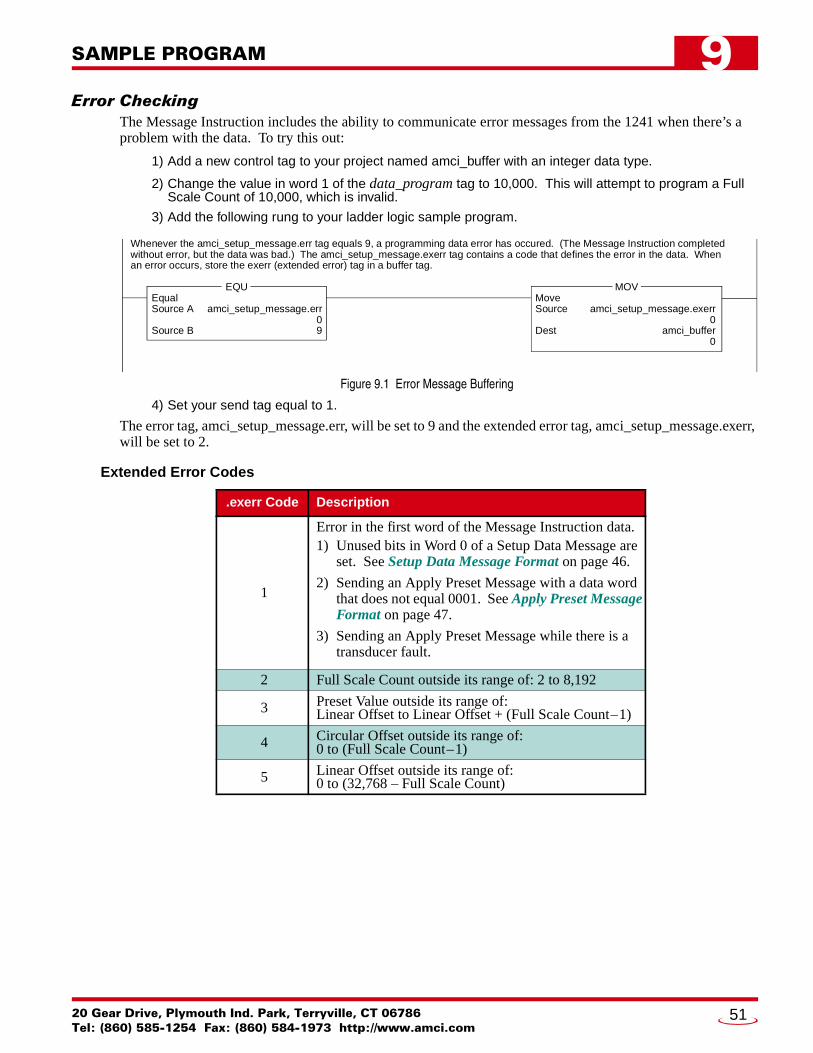
SAMPLE PROGRAM 9
Error CheckingThe Message Instruction includes the ability to communicate error messages from the 1241 when there’s a problem with the data. To try this out:
1) Add a new control tag to your project named amci_buffer with an integer data type.
2) Change the value in word 1 of the data_program tag to 10,000. This will attempt to program a Full Scale Count of 10,000, which is invalid.
3) Add the following rung to your ladder logic sample program.
Figure 9.1 Error Message Buffering
4) Set your send tag equal to 1.
The error tag, amci_setup_message.err, will be set to 9 and the extended error tag, amci_setup_message.exerr, will be set to 2.
Extended Error Codes
.exerr Code Description
1
Error in the first word of the Message Instruction data.1) Unused bits in Word 0 of a Setup Data Message are
set. See Setup Data Message Format on page 46.
2) Sending an Apply Preset Message with a data word that does not equal 0001. See Apply Preset Message Format on page 47.
3) Sending an Apply Preset Message while there is a transducer fault.
2 Full Scale Count outside its range of: 2 to 8,192
3 Preset Value outside its range of:Linear Offset to Linear Offset + (Full Scale Count–1)
4 Circular Offset outside its range of:0 to (Full Scale Count–1)
5 Linear Offset outside its range of:0 to (32,768 – Full Scale Count)
Whenever the amci_setup_message.err tag equals 9, a programming data error has occured. (The Message Instruction completed without error, but the data was bad.) The amci_setup_message.exerr tag contains a code that defines the error in the data. Whenan error occurs, store the exerr (extended error) tag in a buffer tag.
amci_setup_message.err09
EqualSource A
Source B
EQU
amci_setup_message.exerr0
amci_buffer0
MoveSource
Dest
MOV
20 Gear Drive, Plymouth Ind. Park, Terryville, CT 06786Tel: (860) 585-1254 Fax: (860) 584-1973 http://www.amci.com
51

L
ADV ANC ED MIC RO CONTROLS INC.ADV ANC ED MIC RO CONTROLS INC.ADV ANC ED MIC RO CONTROLS INC.ADV ANC ED MIC RO CONTROLS INC.20 GEAR DRIVE, TERRYVILLE, CT 06786 T: (860) 585-1254 F: (860) 584-1973
www.amci.com
EADERS IN ADVANCED CONTROL PRODUCTS