Embed Size (px)
Citation preview

MANAGING PATIENT DOSE IN FLUOROSCOPIC PROCEDURESMANAGING PATIENT DOSE IN MANAGING PATIENT DOSE IN
FLUOROSCOPIC PROCEDURESFLUOROSCOPIC PROCEDURES
Keith J. Strauss, MSc, FAAPMDirector, Radiology Physics & Engineering
Children’s HospitalHarvard Medical School
Keith J. Strauss, Keith J. Strauss, MScMSc, FAAPM, FAAPMDirector, Radiology Physics & EngineeringDirector, Radiology Physics & Engineering
Children’s HospitalChildren’s HospitalHarvard Medical SchoolHarvard Medical School


DILEMASDILEMAS
A. Fluoroscopically Guided Interventions1. Minor2. Life Saving
B. Deterministic Injuries1. None2. Severe
C. Responsible Physician Must Choose to Continue or Stop Complex Interventions
A. Fluoroscopically Guided InterventionsA. Fluoroscopically Guided Interventions1. Minor1. Minor2. Life Saving2. Life Saving
B. Deterministic InjuriesB. Deterministic Injuries1. None1. None2. Severe2. Severe
C. Responsible Physician Must Choose to C. Responsible Physician Must Choose to Continue or Stop Complex InterventionsContinue or Stop Complex Interventions

DILEMASDILEMAS
D. Real-Time Data Needed to Balance1. Radiation Risk 2. Clinical Benefit
E. Physician Hand Cuffed by:1. Regulatory Total Dose Limits2. Inappropriately Applied Reference
Levels
D. D. RealReal--TimeTime Data Needed to BalanceData Needed to Balance1. Radiation Risk 1. Radiation Risk 2. Clinical Benefit2. Clinical Benefit
E. Physician Hand Cuffed by:E. Physician Hand Cuffed by:1. Regulatory Total Dose Limits1. Regulatory Total Dose Limits2. Inappropriately Applied Reference 2. Inappropriately Applied Reference
LevelsLevels

MANAGING PATIENT DOSEMANAGING PATIENT DOSE
Machine DesignMachine Design Operation of MachineOperation of Machine
Exposure RateExposure Rate Fluoroscopy TimeFluoroscopy Time
Exposure/ImageExposure/Image # of # of RecRec ImagesImages
Total Patient Entrance ExposureTotal Patient Entrance Exposure

DILEMASDILEMAS
F. Is Real-Time Data Over Kill?1. Adults
a. Complex Interventionsb. Routine Interventions may not Require
2. All Pediatric Casesa. Elevated Radiosensitivityb. Multiple Follow Up Procedures
F. Is F. Is RealReal--TimeTime Data Over Kill?Data Over Kill?1. Adults1. Adults
a. Complex Interventionsa. Complex Interventionsb. Routine Interventions may not Requireb. Routine Interventions may not Require
2. All Pediatric Cases2. All Pediatric Casesa. Elevated a. Elevated RadiosensitivityRadiosensitivityb. Multiple Follow Up Proceduresb. Multiple Follow Up Procedures

INTRODUCTIONINTRODUCTION
A. Requirements of Patient ExamB. Imaging Equipment Design Must be
Exploited to Minimize Patient DoseC. Acceptance TestingD. Training of StaffE. Real-Time Dose Monitoring Techniques
A. Requirements of A. Requirements of Patient ExamPatient ExamB. Imaging Equipment Design Must be B. Imaging Equipment Design Must be
ExploitedExploited to Minimize Patient Doseto Minimize Patient DoseC. C. Acceptance TestingAcceptance TestingD. D. TrainingTraining of Staffof StaffE. E. RealReal--TimeTime Dose Monitoring TechniquesDose Monitoring Techniques

REQUIREMENTS OF PATIENT EXAMREQUIREMENTS OF PATIENT EXAM
A. Organ System(s) Studied1. Vascular
a. Heartb. Arterialc. Venous
2. NonvascularA. Digestive TractB. Drainages/Punctures
A. Organ System(s) StudiedA. Organ System(s) Studied1. 1. VascularVascular
a. Hearta. Heartb. Arterialb. Arterialc. Venousc. Venous
2. 2. NonvascularNonvascularA. Digestive TractA. Digestive TractB. Drainages/PuncturesB. Drainages/Punctures

REQUIREMENTS OF PATIENT EXAMREQUIREMENTS OF PATIENT EXAM
B. Patient Size Affects:1. Image Quality Requirements2. Patient Sensitivity to Radiation3. Patient Dose4. Required Ancillary Support
a. Equipmentb. Additional Staff
B. Patient Size Affects:B. Patient Size Affects:1. Image Quality Requirements1. Image Quality Requirements2.2. Patient Sensitivity to RadiationPatient Sensitivity to Radiation3. Patient Dose3. Patient Dose4. Required Ancillary Support4. Required Ancillary Support
a. Equipmenta. Equipmentb. Additional Staffb. Additional Staff

PATIENT STOCHASTIC RADIOSENSITIVITYPATIENT STOCHASTIC RADIOSENSITIVITY
C. Radiation Induced Cancer Lifetime Risk From C. Radiation Induced Cancer Lifetime Risk From 1 1 SvSv Whole BodyWhole BodyDoseDose
1. All Ages: 5%1. All Ages: 5%2. 1st Decade: 15%2. 1st Decade: 15%3. 2nd Decade: 8%3. 2nd Decade: 8%4. Middle Age4. Middle Age
1 1 -- 2 %2 %5. 5. Child 10 timesChild 10 times
More SensitiveMore Sensitive

PATIENT STOCHASTIC RADIOSENSITIVITYPATIENT STOCHASTIC RADIOSENSITIVITY
D. Recent AD. Recent A--Bomb Survivor DataBomb Survivor Data1. 35,000 Survivors1. 35,000 Survivors
Doses > Doses > 5 5 radrad2. Received Doses2. Received Doses
Over 50 Years AgoOver 50 Years Ago3. Statistically 3. Statistically SigSig--
nificantnificant Excess Excess Incidence of CancerIncidence of Cancerat at NonextrapolatedNonextrapolatedDoses > 3 Doses > 3 radsrads

PATIENTS COME IN ALL SIZESPATIENTS COME IN ALL SIZESAbdominal GirthAbdominal Girth
(kg) Centimeters(kg) CentimetersAge Mass PA # HVL LAT # HVLAge Mass PA # HVL LAT # HVLNeonateNeonate 22 66 22 66 22NewbornNewborn 33 99 33 1010 3.13.1
1 yr1 yr 1010 1212 44 1414 4.64.65 yr5 yr 1919 1616 5.35.3 2222 7.37.3
12 yr12 yr 3131 1818 66 2727 99AdultAdult 6868 2222 7.37.3 3333 1111
LrgLrg AdultAdult 130130 3232 10.610.6 4848 1616

1 HVL @ 70 KVP
Large Adult
Adult
5 year
1 year
Neonate
PATIENTS COME IN ALL SIZES
5 cm

PATIENTS COME IN ALL SIZESPATIENTS COME IN ALL SIZES
E. Patient Doses Below 70 kVp Are Excessive1. Newborn Fluoro Frame
a. 70 kVp & 0.01 mAs: 0.046 mRb. 45 kVp & 0.08 mAs: 0.20 mR
2. Newborn Cath Framea. 70 kVp & 0.1 mAs: 0.46 mRb. 45 kVp & 0.8 mAs: 1.98 mR
3. Newborn DSA Recorded Imagea. 70 kVp & 3 mAs: 14 mRb. 45 kVp & 24 mAs: 110 mR
E. Patient Doses Below 70 E. Patient Doses Below 70 kVpkVp Are ExcessiveAre Excessive1. Newborn 1. Newborn FluoroFluoro FrameFrame
a. 70 a. 70 kVpkVp & 0.01 & 0.01 mAsmAs: 0.046 : 0.046 mRmRb. 45 b. 45 kVpkVp & 0.08 & 0.08 mAsmAs: 0.20 : 0.20 mRmR
2. Newborn 2. Newborn CathCath FrameFramea. 70 a. 70 kVpkVp & 0.1 & 0.1 mAsmAs: 0.46 : 0.46 mRmRb. 45 b. 45 kVpkVp & 0.8 & 0.8 mAsmAs: 1.98 : 1.98 mRmR
3. Newborn 3. Newborn DSA Recorded ImageDSA Recorded Imagea. 70 a. 70 kVpkVp & 3 & 3 mAsmAs: 14 : 14 mRmRb. 45 b. 45 kVpkVp & 24 & 24 mAsmAs: 110 : 110 mRmR

REQUIREMENTS OF PATIENT EXAMREQUIREMENTS OF PATIENT EXAM
F. Clinical Dynamic Range of mAs per Frame to Maintain Fixed kVp 1. PA Projection
a. 9 Half Value Layersb. Range of 512!
2. LAT Projectiona. 14 Half Value Layersb. Range of 16,000!
F. F. Clinical Dynamic Range of Clinical Dynamic Range of mAsmAs per per Frame to Maintain Fixed Frame to Maintain Fixed kVp kVp 1. PA Projection1. PA Projection
a. 9 Half Value Layersa. 9 Half Value Layersb. Range of 512!b. Range of 512!
2. LAT Projection2. LAT Projectiona. 14 Half Value Layersa. 14 Half Value Layersb. Range of 16,000! b. Range of 16,000!

REQUIREMENTS OF PATIENT EXAMREQUIREMENTS OF PATIENT EXAM
G. Complexity1. Diagnostic Only2. Diagnostic &
Interventionala. Deterministic
Injuries
G. ComplexityG. Complexity1. Diagnostic Only1. Diagnostic Only2. Diagnostic & 2. Diagnostic &
InterventionalInterventionala.a. Deterministic Deterministic
InjuriesInjuries
Injured Patient

REQUIREMENTS OF PATIENT EXAMREQUIREMENTS OF PATIENT EXAM
G. Complexity Increases Deterministic Injury Risk3. Clinical Problems of Children are Complex
a. Congenital Heart Defects and/or Diseasesi. “Black Box”ii. 4 - 8 hr Exam Times
b. 100 - 200 minutes of Fluoro Can Occurc. Malformations in Anatomy Corrected in Stages
i. Up to 10 catheterizations by 21st birthdayii. Multiple interventions over weeks
iii. Radiation Damage to Skin is Cumulative
G. Complexity Increases Deterministic Injury RiskG. Complexity Increases Deterministic Injury Risk3. Clinical Problems of Children are Complex3. Clinical Problems of Children are Complex
a. a. Congenital Heart Defects and/or DiseasesCongenital Heart Defects and/or Diseasesi. “Black Box”i. “Black Box”ii. 4 ii. 4 -- 8 hr Exam Times8 hr Exam Times
b. b. 100 100 -- 200 minutes of 200 minutes of FluoroFluoro Can OccurCan Occurc. c. Malformations in Anatomy Corrected in StagesMalformations in Anatomy Corrected in Stages
i. Up to 10 catheterizations by 21st birthdayi. Up to 10 catheterizations by 21st birthdayii. Multiple interventions over weeksii. Multiple interventions over weeks
iii. Radiation Damage to Skin is Cumulativeiii. Radiation Damage to Skin is Cumulative

IMAGING EQUIPMENT DESIGNIMAGING EQUIPMENT DESIGN
VARIABLERATE
PULSED FLUOROSCOPY
VARIABLEVARIABLERATE RATE
PULSED PULSED FLUOROSCOPYFLUOROSCOPY

IMAGING EQUIPMENT DESIGNIMAGING EQUIPMENT DESIGN
A. Variable Rate Pulsed Fluoroscopy1. Alternating if Biplane Configuration
a. Scatter from Orthogonal Plane Eliminatedb. Limited Subject Contrast Maintained
2. Variable Ratea. 30, 15, & 7.5 pulses/sec: Cath Labb. 30, 15, 7.5, 4, & 3 pulses/sec: DSA LabC. 7.5, 3.75, 1.88, 1 pulses/sec: GI/GU Lab
A. Variable Rate Pulsed FluoroscopyA. Variable Rate Pulsed Fluoroscopy1. Alternating if Biplane Configuration1. Alternating if Biplane Configuration
a. Scatter from Orthogonal Plane Eliminateda. Scatter from Orthogonal Plane Eliminatedb. Limited Subject Contrast Maintainedb. Limited Subject Contrast Maintained
2. Variable Rate2. Variable Ratea. 30, 15, & 7.5 pulses/sec: a. 30, 15, & 7.5 pulses/sec: CathCath LabLabb. 30, 15, 7.5, 4, & 3 pulses/sec: DSA Labb. 30, 15, 7.5, 4, & 3 pulses/sec: DSA LabC. 7.5, 3.75, 1.88, 1 pulses/sec: GI/GU LabC. 7.5, 3.75, 1.88, 1 pulses/sec: GI/GU Lab

IMAGING EQUIPMENT DESIGNIMAGING EQUIPMENT DESIGN
A. Variable Rate Pulsed Fluoroscopy3. Image Quality vs Radiation Dose
a. Proper Pulse Width Minimizes Temporal Information Loss
b. Pulse Width Rangesi. Pediatrics: 1 - 5 msecii. Adults: 3 - 10 msec
A. Variable Rate Pulsed FluoroscopyA. Variable Rate Pulsed Fluoroscopy3. Image Quality 3. Image Quality vs vs Radiation DoseRadiation Dose
a. Proper Pulse Width Minimizes Temporal a. Proper Pulse Width Minimizes Temporal Information LossInformation Loss
b. b. Pulse Width RangesPulse Width Rangesi. Pediatrics: 1 i. Pediatrics: 1 -- 5 5 msecmsecii. Adults: 3 ii. Adults: 3 -- 10 10 msecmsec

IMAGING EQUIPMENT DESIGNIMAGING EQUIPMENT DESIGN
A. Variable Rate Pulsed Fluoroscopy3. Image Quality vs Radiation Dose
c. Increased Perceived Noise Unacceptable if: i. Exposure per pulse unchanged with
reduced pulse rateii. Loss of Temporal Resolution is not the
Cause of Rejection of Variable Rate Pulsed Fluoroscopy
A. Variable Rate Pulsed FluoroscopyA. Variable Rate Pulsed Fluoroscopy3. Image Quality 3. Image Quality vs vs Radiation DoseRadiation Dose
c. Increased Perceived Noise Unacceptable if: c. Increased Perceived Noise Unacceptable if: i.i. Exposure per pulse unchanged with Exposure per pulse unchanged with
reduced pulse ratereduced pulse rateii. Loss of Temporal Resolution is not theii. Loss of Temporal Resolution is not the
Cause of Rejection of Variable Rate Cause of Rejection of Variable Rate Pulsed FluoroscopyPulsed Fluoroscopy

IMAGING EQUIPMENT DESIGNIMAGING EQUIPMENT DESIGN
A. Variable Rate Pulsed Fluoroscopy3. Image Quality vs Radiation Dose
c. Perceived Noise Compensationii. EERIR/Frame α 1/(Pulse Frequency)1/2
• Less frame integration by eye• EERIR/Frame Increased as Pulse Rate
Decreases• Relationship holds above 5 pulses/sec
A. Variable Rate Pulsed FluoroscopyA. Variable Rate Pulsed Fluoroscopy3. Image Quality 3. Image Quality vsvs Radiation DoseRadiation Dose
c. Perceived Noise Compensationc. Perceived Noise Compensationii. ii. EERIR/Frame EERIR/Frame α α 1/(Pulse Frequency)1/(Pulse Frequency)1/21/2
•• Less frame integration by eyeLess frame integration by eye•• EERIR/Frame Increased as Pulse Rate EERIR/Frame Increased as Pulse Rate
DecreasesDecreases•• Relationship holds above 5 pulses/secRelationship holds above 5 pulses/sec

IMAGING EQUIPMENT DESIGNIMAGING EQUIPMENT DESIGN
A. Variable Rate Pulsed Fluoroscopy4. Tube Current
a. Minimum: 10 mAb. Maximum: 100 mA
5. Desired Fixed High Voltage ~ 70 kVa. Requires mAs Range of 500!
i. Too many vendors do not vary tube current and pulse width!
ii. At best have a mAs range of 50
6. 70 kVp may Occur for Only One Size Patient!
A. Variable Rate Pulsed FluoroscopyA. Variable Rate Pulsed Fluoroscopy4. Tube Current4. Tube Current
a. Minimum: 10 a. Minimum: 10 mAmAb. Maximum: 100 b. Maximum: 100 mAmA
5. Desired Fixed High Voltage ~ 70 kV5. Desired Fixed High Voltage ~ 70 kVa. Requires a. Requires mAsmAs Range of 500!Range of 500!
i. Too many vendors do not vary i. Too many vendors do not vary tube tube currentcurrent and and pulse widthpulse width! !
ii. At best have a ii. At best have a mAsmAs range of 50range of 50
6. 70 6. 70 kVpkVp may Occur for Only One Size Patient!may Occur for Only One Size Patient!

IMAGING EQUIPMENT DESIGNIMAGING EQUIPMENT DESIGN
A. Variable Rate Pulsed FluoroscopyA. Variable Rate Pulsed Fluoroscopy7. Traditional Modulation of Technical Factors7. Traditional Modulation of Technical Factors
a. a. Pulse WidthPulse Width at Maximumat Maximumb. b. Tube CurrentTube Current
i. i. FluoroFluoro: 50 : 50 mAmAii. ii. AcquistionAcquistion: Maximum Tube Loading: Maximum Tube Loading
c. c. kVpkVp ModulatedModulatedi. Minimized for Large Patientsi. Minimized for Large Patientsii. Excessive Dose for Small Patientsii. Excessive Dose for Small Patients

IMAGING EQUIPMENT DESIGNIMAGING EQUIPMENT DESIGN
A. Variable Rate Pulsed Fluoroscopy8. Preferred Modulation of Technique Factors
a. Starting Valuesi. 70 kVp
ii. 3 msecb. Modulation Hierarchy
i. Tube Currentii. Pulse Width
iii. High Voltage
A. Variable Rate Pulsed FluoroscopyA. Variable Rate Pulsed Fluoroscopy8. Preferred Modulation of Technique Factors 8. Preferred Modulation of Technique Factors
a. Starting Valuesa. Starting Valuesi. 70 i. 70 kVpkVp
ii. 3 ii. 3 msecmsecb. Modulation Hierarchyb. Modulation Hierarchy
i. Tube Currenti. Tube Currentii. Pulse Widthii. Pulse Width
iii. High Voltageiii. High Voltage

IMAGING EQUIPMENT DESIGNIMAGING EQUIPMENT DESIGN
B. Continuous Fluoroscopy1. Preferred Technique Modulation
a. Starting kVp: 70b. Tube Current Modulated: 0.1 - 4 mAc. kVp Modulated Last
B. Continuous FluoroscopyB. Continuous Fluoroscopy1. Preferred Technique Modulation1. Preferred Technique Modulation
a. Starting a. Starting kVpkVp: 70: 70b. Tube Current Modulated: 0.1 b. Tube Current Modulated: 0.1 -- 4 4 mAmAc. c. kVpkVp Modulated LastModulated Last

kVp/mA AERC Algorithm
0.01
0.1
1
10
30 40 50 60 70 80 90 100 110
kVp
Tube Current (mA)

IMAGING EQUIPMENT DESIGNIMAGING EQUIPMENT DESIGN
C. Variable Rate Radiographic Acquisitions1. Cath Lab
a. Same Specifications as Pulsed Fluoro Except:i. Variable Rate: 60, 30, & 15 pulses/secii. Tube Current:
• Neonate to 2 Yr: 100 mA• 2 - 12 Yr: 300 - 400 mA• 12 Yr - Adult: Maximum Tube Loading
iii. High Voltage ~ 70 kV for Patients < 12 Yr
C. Variable Rate Radiographic AcquisitionsC. Variable Rate Radiographic Acquisitions1. 1. CathCath LabLab
a. Same Specifications as Pulsed a. Same Specifications as Pulsed FluoroFluoro ExceptExcept::i. i. Variable RateVariable Rate: 60, : 60, 30, & 1530, & 15 pulses/secpulses/secii. ii. Tube CurrentTube Current::
•• Neonate to 2 Yr: 100 Neonate to 2 Yr: 100 mAmA•• 2 2 -- 12 Yr: 300 12 Yr: 300 -- 400 400 mAmA•• 12 Yr 12 Yr -- Adult: Maximum Tube LoadingAdult: Maximum Tube Loading
iii. iii. High VoltageHigh Voltage ~ 70 kV for Patients < 12 Yr~ 70 kV for Patients < 12 Yr

IMAGING EQUIPMENT DESIGNIMAGING EQUIPMENT DESIGN
C. Variable Rate Radiographic AcquisitionsC. Variable Rate Radiographic Acquisitions2. Vascular Lab2. Vascular Lab
a. a. Variable RateVariable Rate: 7.5 : 7.5 -- 0.5 pulses/sec0.5 pulses/secb. b. Tube CurrentTube Current
i. Neonate to 2 yr: 200 i. Neonate to 2 yr: 200 mAmAii. 2 ii. 2 -- 6 Yr: 400 6 Yr: 400 -- 600 600 mAmAiii. 6 Yr iii. 6 Yr -- Adult: Maximum Tube LoadingAdult: Maximum Tube Loading
c. c. High VoltageHigh Voltage ~ 70 kV for Patients < 12 Yr~ 70 kV for Patients < 12 Yr

IMAGING EQUIPMENT DESIGNIMAGING EQUIPMENT DESIGN
C. Variable Rate Radiographic Acquisitions3. Preferred Technique Modulation :
a. Starting Valuesi. 70 kVp
ii. 3 msecb. Modulation Hierarchy
i. Tube Currentii. Pulse Width
iii. High Voltage
C. Variable Rate Radiographic AcquisitionsC. Variable Rate Radiographic Acquisitions3. Preferred Technique Modulation :3. Preferred Technique Modulation :
a. Starting Valuesa. Starting Valuesi. 70 i. 70 kVpkVp
ii. 3 ii. 3 msecmsecb. Modulation Hierarchyb. Modulation Hierarchy
i. Tube Currenti. Tube Currentii. Pulse Widthii. Pulse Width
iii. High Voltageiii. High Voltage
IMAGING EQUIPMENT DESIGNIMAGING EQUIPMENT DESIGN
D. Spectral Beam Filtration: D. Spectral Beam Filtration: Change in Quality of XChange in Quality of X--rayraySpectrum:Spectrum: Match Energy of XMatch Energy of X--rays to Absorption ofrays to Absorption ofContrast MediaContrast Media1.1. PassPass 33 33 -- 40 40 keV keV
XX--raysrays2. 2. AttenuateAttenuate
a. <33 a. <33 keVkeV XX--raysraysAffects DoseAffects Dose
b. > 40 b. > 40 keVkeV XX--rayrayAffects ContrastAffects Contrast

IMAGING EQUIPMENT DESIGNIMAGING EQUIPMENT DESIGN
D. Spectral Beam Filtration:D. Spectral Beam Filtration:3. X3. X--ray Tube Continuous Loading > 2 kW ray Tube Continuous Loading > 2 kW 4. 0.1 4. 0.1 -- 0.9 mm 0.9 mm
Cu FiltrationCu Filtration5. Low Energy5. Low Energy
AttenuatedAttenuated6. 6. kVpkVp IncreasesIncreases7. 7. Excessive Excessive
Effective Effective keVkeV

IMAGING EQUIPMENT DESIGNIMAGING EQUIPMENT DESIGN
D. Spectral Beam Filtration:D. Spectral Beam Filtration:8. Modify Algorithm Controlling 8. Modify Algorithm Controlling kVpkVp & & mA mA 9. 9. kVpkVp ReducedReduced
to 60 to 60 kVpkVp10. 10. XX--ray Intensity ray Intensity
Too SmallToo Small

IMAGING EQUIPMENT DESIGNIMAGING EQUIPMENT DESIGN
D. Spectral Beam Filtration:D. Spectral Beam Filtration:11. Increase 11. Increase mAmA to maximum kWto maximum kW12. 12. AdultsAdults: Fluoroscopy only : Fluoroscopy only << 0.2 mm Cu0.2 mm Cu13. 13. PediatricsPediatrics: Fluoroscopy & Radiographic: Fluoroscopy & Radiographic

IMAGING EQUIPMENT DESIGNIMAGING EQUIPMENT DESIGN
D. Spectral Beam Filtration:D. Spectral Beam Filtration:14. Summary14. Summary
a. Added Filtera. Added Filterb. Reduced High Voltageb. Reduced High Voltagec. Increased Tube Currentc. Increased Tube Currentd. Machine should d. Machine should automatically select:automatically select:
i. Thickest filteri. Thickest filterii. Resulting in 60 ii. Resulting in 60 -- 70 70 kVp kVp iii. Based on current iii. Based on current fluorofluoro attenuation dataattenuation data

IMAGING EQUIPMENT DESIGNIMAGING EQUIPMENT DESIGN
E. Last Image HoldE. Last Image Hold1. Last Fluoroscopic Frame Stored and1. Last Fluoroscopic Frame Stored and
Continuously Displayed on TV MonitorContinuously Displayed on TV Monitor2. Poorer Quality due to Loss of Multiple 2. Poorer Quality due to Loss of Multiple
Frame Integration by EyeFrame Integration by Eye3. Allows Extended Viewing of Anatomy3. Allows Extended Viewing of Anatomy
Without Without FurtherFurther RadiationRadiation

IMAGING EQUIPMENT DESIGNIMAGING EQUIPMENT DESIGN
F. F. FluoroFluoro Image StoreImage Store1. During 1. During RealtimeRealtime FluoroscopyFluoroscopy
a. Frame Selected by Operator and a. Frame Selected by Operator and b. Electronically Storedb. Electronically Stored
2. 2. Poorer QualityPoorer Quality due to:due to:a. Loss of Multiple Frame Integration by Eyea. Loss of Multiple Frame Integration by Eyeb. Lower Exposure at Plane of Image Receptorb. Lower Exposure at Plane of Image Receptor
3. Radiographic Acquisition Dose Avoided3. Radiographic Acquisition Dose Avoided4. 4. Stored Fluoroscopic FrameStored Fluoroscopic Frame ArchivedArchived
Electronically or on FilmElectronically or on Film

IMAGING EQUIPMENT DESIGNIMAGING EQUIPMENT DESIGN
G. Spatial Beam ShapingG. Spatial Beam Shaping1. Equalization Filters: Attenuation Compensation1. Equalization Filters: Attenuation Compensation
a. Linear & a. Linear & RotaRota--tionaltional MovementMovement
b. b. Tapered Lead Tapered Lead --Acrylic BladesAcrylic Blades
c. Interchangeablec. Interchangeabled. Integral Dosed. Integral Dose
ReductionReduction

IMAGING EQUIPMENT DESIGNIMAGING EQUIPMENT DESIGN
G. Spatial Beam ShapingG. Spatial Beam Shaping2. Collimator Adjustment without 2. Collimator Adjustment without FluoroFluoro RadiationRadiation
a. Collimator Blade Location Updateda. Collimator Blade Location Updatedon Monitor as Blades are movedon Monitor as Blades are moved
b. b. Less Dose Due to AdjustmentLess Dose Due to Adjustment
c. Integral Dose Reductionc. Integral Dose Reduction

IMAGING EQUIPMENT DESIGNIMAGING EQUIPMENT DESIGN
H. Filtration Added to X-Ray Beam“Spectral Beam” Filtering1. Effective Energy of Beam Increases2. Less X-rays @ same EERIR3. Quantum Mottle Increases for same EERIR4. Double EERIR wrt Standard Filtration5. EERfilters < EERstd filters
H. Filtration Added to XH. Filtration Added to X--Ray BeamRay Beam“Spectral Beam” Filtering“Spectral Beam” Filtering1. Effective Energy of Beam Increases1. Effective Energy of Beam Increases2. Less X2. Less X--rays @ same EERIRrays @ same EERIR3. Quantum Mottle Increases for same EERIR3. Quantum Mottle Increases for same EERIR4. 4. Double EERIR Double EERIR wrtwrt Standard FiltrationStandard Filtration5. 5. EEREERfiltersfilters < < EEREERstdstd filtersfilters

IMAGING EQUIPMENT DESIGNIMAGING EQUIPMENT DESIGN
I. Electronically Adjustable Aperturein Front of TV Camera 1. Directly Controls EERIR
Entrance Exposure Rate to Image Receptor
2. Indirectly Controls EEREntrance Exposure Rate to Patient
I. Electronically Adjustable ApertureI. Electronically Adjustable Aperturein Front of TV Camera in Front of TV Camera 1. 1. DirectlyDirectly Controls Controls EERIREERIR
Entrance Exposure Rate to Image ReceptorEntrance Exposure Rate to Image Receptor
2. 2. IndirectlyIndirectly Controls EERControls EEREntrance Exposure Rate to PatientEntrance Exposure Rate to Patient

IMAGING EQUIPMENT DESIGNIMAGING EQUIPMENT DESIGN
I. Electronically Adjustable Aperture3. Pulse Fluoro Frequency Change
a. IIIER α 1/(Pulse Frequency)1/2
for Pulse Frequencies > 5b. Corrects Increased Perceived Noise
due to Less Integration of TV Framesby Eye
c. EERIR/Frame α Constantfor Pulse Frequencies < 5
I. Electronically Adjustable ApertureI. Electronically Adjustable Aperture3. Pulse 3. Pulse FluoroFluoro Frequency ChangeFrequency Change
a. a. IIIER IIIER α α 1/(Pulse Frequency)1/(Pulse Frequency)1/21/2
for Pulse Frequencies > 5for Pulse Frequencies > 5b. Corrects Increased Perceived Noiseb. Corrects Increased Perceived Noise
due to Less Integration of TV Framesdue to Less Integration of TV Framesby Eyeby Eye
c. c. EERIR/Frame EERIR/Frame α α ConstantConstantfor Pulse Frequencies < 5for Pulse Frequencies < 5

IMAGING EQUIPMENT DESIGNIMAGING EQUIPMENT DESIGN
I. Electronically Adjustable Aperture4. Function of FoV Change
a. Older Equipment With Fixed Aperture (II)i. EERIR α 1/FoV2
ii. Corrects Loss of Minification Gainiii. Maintained Brightness on Monitoriv. Reduced Quantum Mottlev. Significant Increase of EERIR in Mag
modes
I. Electronically Adjustable ApertureI. Electronically Adjustable Aperture4. Function of 4. Function of FoVFoV ChangeChange
a. Older Equipment With Fixed Aperture (II)a. Older Equipment With Fixed Aperture (II)i. i. EERIR EERIR α α 1/FoV1/FoV22
ii. Corrects Loss of ii. Corrects Loss of MinificationMinification GainGainiii. Maintained Brightness on Monitoriii. Maintained Brightness on Monitoriv. Reduced Quantum Mottleiv. Reduced Quantum Mottlev. v. Significant Increase of EERIR in Significant Increase of EERIR in MagMag
modesmodes

IMAGING EQUIPMENT DESIGNIMAGING EQUIPMENT DESIGN
I. Electronically Adjustable Aperture4. Function of FoV Change
b. Adjustable Aperture (II)i. EERIR α 1/FoV
ii. Quantum Mottle (Absolute Noise)Independent of FoV
iii. Perceived Noise Increases with SharperImage of Reduced FoV
iv. Correct with Increased EERIRv. Less Increase of EERIR in Mag modes
I. Electronically Adjustable ApertureI. Electronically Adjustable Aperture4. Function of 4. Function of FoVFoV ChangeChange
b. b. Adjustable Aperture (II)Adjustable Aperture (II)i. i. EERIR EERIR α α 1/1/FoVFoV
ii. Quantum Mottle (Absolute Noise)ii. Quantum Mottle (Absolute Noise)Independent of Independent of FoVFoV
iii. Perceived Noise Increases with Sharperiii. Perceived Noise Increases with SharperImage of Reduced Image of Reduced FoVFoV
iv. Correct with Increased EERIRiv. Correct with Increased EERIRv. v. Less Increase of EERIR in Less Increase of EERIR in MagMag modesmodes

IMAGING EQUIPMENT DESIGNIMAGING EQUIPMENT DESIGN
I. Electronically Adjustable Aperture4. Function of FoV Change
c. Adjustable Aperture Opened in Mag Modesi. Conventional Image Intensifiers
ii. EERIR α Constantiii. Increases in Perceived Noise Must be
Tolerated by Operatoriii. Perceived Noise Increases with Sharper
Image of Reduced FoViv. Patient Dose is Unchanged
I. Electronically Adjustable ApertureI. Electronically Adjustable Aperture4. Function of 4. Function of FoVFoV ChangeChange
c. Adjustable Aperture Opened c. Adjustable Aperture Opened in in MagMag ModesModesi. i. Conventional Image IntensifiersConventional Image Intensifiers
ii. ii. EERIR EERIR α α ConstantConstantiii. Increases in Perceived Noise Must beiii. Increases in Perceived Noise Must be
Tolerated by OperatorTolerated by Operatoriii. Perceived Noise Increases with Sharperiii. Perceived Noise Increases with Sharper
Image of Reduced Image of Reduced FoVFoViv. iv. Patient Dose is UnchangedPatient Dose is Unchanged

IMAGING EQUIPMENT DESIGNIMAGING EQUIPMENT DESIGN
I. Electronically Adjustable Aperture4. Function of FoV Change
d. Flat Plate Image Receptorsi. EERIR α Constant
ii. Sharpness Minimally Affected by FoV- Determined by Size of Plate’s Pixels
iii. Perceived Noise is Constantiv. Patient Dose Should be Unchanged
I. Electronically Adjustable ApertureI. Electronically Adjustable Aperture4. Function of 4. Function of FoVFoV ChangeChange
d. d. Flat Plate Image ReceptorsFlat Plate Image Receptorsi. i. EERIR EERIR α α ConstantConstant
ii. Sharpness Minimally Affected by ii. Sharpness Minimally Affected by FoVFoV-- Determined by Size of Plate’s PixelsDetermined by Size of Plate’s Pixels
iii. Perceived Noise is Constantiii. Perceived Noise is Constantiv. Patient Dose iv. Patient Dose Should beShould be UnchangedUnchanged

IMAGING EQUIPMENT DESIGNIMAGING EQUIPMENT DESIGN
I. Electronically Adjustable Aperture5. Operator Selectable EERIR:
Task Orienteda. Low (Half of Medium)b. Mediumc. High (Double Medium)
I. Electronically Adjustable ApertureI. Electronically Adjustable Aperture5. 5. Operator Selectable EERIR:Operator Selectable EERIR:
Task OrientedTask Orienteda. Low (Half of Medium)a. Low (Half of Medium)b. Mediumb. Mediumc. High (Double Medium)c. High (Double Medium)

IMAGING EQUIPMENT DESIGNIMAGING EQUIPMENT DESIGN
I. Electronically Adjustable Aperture5. Operator Selectable EERIR:
d. Manufacturer Dependente. Flat Plate Receptor Example (20 cm girth)
Parameter Vendor A Vendor BLow EERIR (mR/m) 5.5 9.2Low EER (R/m) 2.1 2.8Nor EERIR (mR/m) 14 7.4Nor EER (R/m) 5.8 4
I. Electronically Adjustable ApertureI. Electronically Adjustable Aperture5. Operator Selectable EERIR:5. Operator Selectable EERIR:
d. d. Manufacturer DependentManufacturer Dependente.e. Flat Plate Receptor Example (20 cm girth)Flat Plate Receptor Example (20 cm girth)
Parameter Vendor A Vendor BParameter Vendor A Vendor BLow EERIR (Low EERIR (mRmR/m)/m) 5.55.5 9.29.2Low EER (R/m)Low EER (R/m) 2.12.1 2.82.8Nor EERIR (Nor EERIR (mRmR/m)/m) 1414 7.47.4Nor EER (R/m)Nor EER (R/m) 5.85.8 44

ACCEPTANCE TESTINGACCEPTANCE TESTING
A. Why Acceptance Testing?A. Why Acceptance Testing?1. Identify & Eliminate Faulty Components1. Identify & Eliminate Faulty Components2. Insure Proper Setup of Equipment2. Insure Proper Setup of Equipment
a. Clinical Choicesa. Clinical Choicesi. Clinical Requirementsi. Clinical Requirementsii. Design Features of Equipmentii. Design Features of Equipment
b. Measurement Techniquesb. Measurement Techniquesi. Test Equipment Availablei. Test Equipment Availableii. Design Requirements of Clinical Unitii. Design Requirements of Clinical Unit

ACCEPTANCE TESTINGACCEPTANCE TESTING
B. What Should be Measured?B. What Should be Measured?1. 1. Entrance Exposure Rate to Image ReceptorEntrance Exposure Rate to Image Receptor
a. All Fluoroscopic Modesa. All Fluoroscopic Modesb. All Recording Modesb. All Recording Modes
2. 2. Entrance Exposure Rate to PatientEntrance Exposure Rate to Patienta. Maximuma. Maximumb. All Patient Sizes to be Imagedb. All Patient Sizes to be Imaged
3. 3. Do Not AssumeDo Not Assume Installer has Addressed Installer has Addressed These Issues!!!!These Issues!!!!

ACCEPTANCE TESTINGACCEPTANCE TESTING
C. Appropriate Performance Levels?C. Appropriate Performance Levels?1. 1. EERIREERIRvariablevariable
a. EERIR/Fr =a. EERIR/Fr = ( (EERIREERIR3030/Fr) / (Pulse Frequency)/Fr) / (Pulse Frequency)1/21/2
b. b. EERIREERIRspectralspectral filterfilter = 2 x = 2 x EERIREERIRstdstd filterfilter
c. EERIR c. EERIR α α 1/FoV1/FoV22
d. EERIR d. EERIR α α 1/1/FoVFoVe. EERIR e. EERIR α α Constant (function of Constant (function of FoVFoV Flat Plate)Flat Plate)f. 1/2 x f. 1/2 x EERIREERIRhighhigh = = EERIREERIRnormalnormal
g. g. EERIREERIRnormalnormal = = EERIREERIRlowlow x 2x 2

ACCEPTANCE TESTINGACCEPTANCE TESTING
C. Appropriate Performance Levels?C. Appropriate Performance Levels?2. EERIR?2. EERIR?
a. Set EERIR to Provide a. Set EERIR to Provide AdequateAdequate Image QualityImage Qualityb. b. Minimum EERIRMinimum EERIR
i. Equipment Designi. Equipment Designii. Image Quality Requirementsii. Image Quality Requirements
•• Diameter of VesselDiameter of Vessel•• Concentration of Contrast MaterialConcentration of Contrast Material

ACCEPTANCE TESTINGACCEPTANCE TESTING
C. Appropriate Performance Levels?C. Appropriate Performance Levels?2. EERIR?2. EERIR?
b.b. Minimum EERIRMinimum EERIRi. i. Exposure Exposure α α 1 / p1 / p22cc22DD22
p = precisionp = precisionc = concentration of contrastc = concentration of contrastD = diameter of vesselD = diameter of vessel
ii. Predicts ii. Predicts Minimum ExposureMinimum Exposure to Detectto DetectContrast Filled VesselsContrast Filled Vessels
iii. Predicts Improved Image Quality withiii. Predicts Improved Image Quality withanyany Reduced Perceived Noise (pReduced Perceived Noise (p22) )

ACCEPTANCE TESTINGACCEPTANCE TESTING
C. Appropriate Performance Levels?C. Appropriate Performance Levels?2. EERIR?2. EERIR?
c.c. Maximum EERIRMaximum EERIRi. Perceived Noise a Function of System i. Perceived Noise a Function of System
NoiseNoiseii. System Noise = [QMii. System Noise = [QM22 + EN+ EN22]]0.50.5
QM = Quantum MottleQM = Quantum MottleEN = Electronic NoiseEN = Electronic Noise

ACCEPTANCE TESTINGACCEPTANCE TESTING
C. Appropriate Performance Levels?C. Appropriate Performance Levels?2. EERIR?2. EERIR?
c.c. Maximum EERIRMaximum EERIRiii. Want QM < ENiii. Want QM < ENiv. When QM = EN Further Increases in iv. When QM = EN Further Increases in
EERIR are WastedEERIR are Wastedv. Excessive EERIR Degrades Image Qualityv. Excessive EERIR Degrades Image Quality
•• 10 R/min Limit10 R/min Limit•• Loss of Brightness on TV MonitorLoss of Brightness on TV Monitor

ACCEPTANCE TESTINGACCEPTANCE TESTINGACCEPTANCE TESTINGEntrance Exposure Rate to Image Intensifier
22 cm FOV @ 80 kVpStandard Filtration & kVp/mA Power Curves
30 Pulses per SecondOperational Mode EERII Range (µR/frame)Standard Fluoroscopy 1.5 - 2.5High Dose Fluoroscopy 3 - 6Digital Angiography 50 - 100Digital Subtraction Angio 500 - 1000Cardiac Digital 8 - 10Cine Film 10 - 15
Entrance Exposure Rate to Entrance Exposure Rate to Image IntensifierImage Intensifier22 cm FOV @ 80 22 cm FOV @ 80 kVpkVp
Standard Filtration & Standard Filtration & kVpkVp//mAmA Power CurvesPower Curves30 Pulses per Second30 Pulses per Second
Operational ModeOperational Mode EERII Range (µR/frame)EERII Range (µR/frame)Standard FluoroscopyStandard Fluoroscopy 1.5 1.5 -- 2.52.5High Dose FluoroscopyHigh Dose Fluoroscopy 3 3 -- 66Digital Digital AngiographyAngiography 50 50 -- 100100Digital Subtraction Digital Subtraction AngioAngio 500 500 -- 10001000Cardiac DigitalCardiac Digital 8 8 -- 1010Cine FilmCine Film 10 10 -- 1515

ACCEPTANCE TESTINGACCEPTANCE TESTING
C. Appropriate Performance Levels?C. Appropriate Performance Levels?2. EERIR?2. EERIR?
d.d. FPDER: Flat Plate Detector Exposure RateFPDER: Flat Plate Detector Exposure Ratei. Standard Filtration & i. Standard Filtration & kVpkVp//mAmA Power CurvesPower Curves
ii. 20 cm FOV @ 80 ii. 20 cm FOV @ 80 kVpkVpiii. 30 Pulses per Secondiii. 30 Pulses per Second
Operational ModeOperational Mode EERIR Range (µR/frame)EERIR Range (µR/frame)Standard FluoroscopyStandard Fluoroscopy 2.52.5Digital Digital AngiographyAngiography 50 50 -- 100100Cardiac DigitalCardiac Digital 10 10 -- 1515

ACCEPTANCE TESTINGACCEPTANCE TESTING
C. Appropriate Performance Levels?C. Appropriate Performance Levels?2. EERIR?2. EERIR?
d.d. FPDER: Flat Plate Detector Exposure FPDER: Flat Plate Detector Exposure RateRate
iv. iv. Unchanged Unchanged as as FoVFoV changeschangesv. v. JustificationJustification
•• Measured Sharpness of image Measured Sharpness of image basically independent of basically independent of FoVFoV
•• Sharpness of image similar to 5” Sharpness of image similar to 5” FoVFoV IIII

ACCEPTANCE TESTINGACCEPTANCE TESTING
C. Appropriate Performance Levels?C. Appropriate Performance Levels?3. EER?3. EER?
a.a. Entrance Exposure RateEntrance Exposure Rateb. Where?b. Where?
i. Patient’s Skin?i. Patient’s Skin?ii. Reference Point?ii. Reference Point?

ACCEPTANCE TESTINGACCEPTANCE TESTING
C. Appropriate Performance Levels?C. Appropriate Performance Levels?3. EER3. EER
c. Three c. Three FluoroscopicFluoroscopicGeomentriesGeomentries::FIXEDFIXED
i. SIDi. SIDii. SSDii. SSD
iii. SADiii. SAD
Fig 7
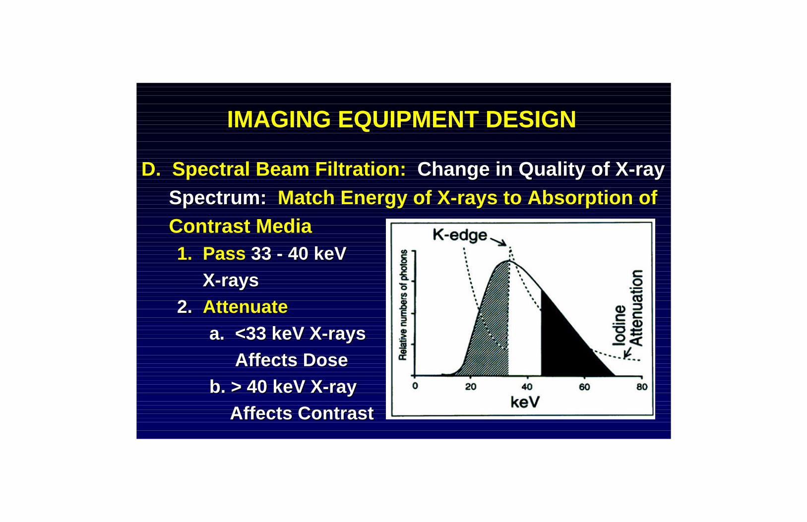
ACCEPTANCE TESTINGACCEPTANCE TESTINGC. Appropriate Performance Levels?C. Appropriate Performance Levels?
3. EER3. EERd. Common d. Common Dose Dose
Reference PointsReference Pointsi. IECi. IEC
15 cm 15 cm ii. FDAii. FDA
30 cm30 cm

ACCEPTANCE TESTINGACCEPTANCE TESTING
C. Appropriate Performance Levels?C. Appropriate Performance Levels?3. EER3. EER
e. Other Important Parameterse. Other Important Parametersi. i. α α mAmA
ii. ii. α α kVpkVp22
iii. ~ iii. ~ α α ~ EERIR~ EERIR•• Added FiltrationAdded Filtration•• Beam Shaping FiltersBeam Shaping Filters•• Grid FactorsGrid Factors

ACCEPTANCE TESTINGACCEPTANCE TESTING
C. Appropriate Performance Levels?C. Appropriate Performance Levels?3. EER3. EER
e. Other Important Parameterse. Other Important Parametersiv. Function of Patient Sizeiv. Function of Patient Sizev. v. αα (1 / distance)(1 / distance)22

ACCEPTANCE TESTINGACCEPTANCE TESTING
C. Appropriate Performance Levels?C. Appropriate Performance Levels?4. Affect of Increasing4. Affect of Increasing
Patient SizePatient Sizea. Fixed SIDa. Fixed SID
i. Attenuation?i. Attenuation?ii. Shorterii. Shorter
SSD?SSD? 8a

ACCEPTANCE TESTINGACCEPTANCE TESTING
C. Appropriate Performance Levels?C. Appropriate Performance Levels?4. Affect of Increasing 4. Affect of Increasing
Patient SizePatient Sizeb. Fixed SSDb. Fixed SSD
i. Attenuation?i. Attenuation?ii. Longerii. Longer
SID?SID?8b

ACCEPTANCE TESTINGACCEPTANCE TESTING
C. Appropriate Performance Levels?C. Appropriate Performance Levels?4. Affect of Increasing4. Affect of Increasing
Patient SizePatient Sizec. Fixed SADc. Fixed SAD
i. Attenuation?i. Attenuation?ii. Longerii. Longer
SID?SID?iii. Shorteriii. Shorter
SSD?SSD?
8c

ACCEPTANCE TESTINGACCEPTANCE TESTING
D. Measurement PitfallsD. Measurement Pitfalls1. Dosimeter1. Dosimeter
a. Constant a. Constant Energy ResponseEnergy Responsei. 50 i. 50 -- 120 120 kVpkVp
ii. 2 ii. 2 -- 14 mm Al HVL14 mm Al HVLb. b. Collection EfficiencyCollection Efficiency
95% @ 2,000 95% @ 2,000 -- 10,000 R/min10,000 R/minc. c. LeakageLeakage < 1 x 10< 1 x 10--1414 AmpAmp

ACCEPTANCE TESTINGACCEPTANCE TESTING
1. Dosimeter1. Dosimeterd.d. Shape Shape of Ionization Chamberof Ionization Chamber
i. i. Parallel PlateParallel Plate•• Fits behind GridsFits behind Grids•• High Collection EfficiencyHigh Collection Efficiency•• XX--ray “Transparency”ray “Transparency”
ii. ii. CylindricalCylindrical•• No Directional ResponseNo Directional Response

ACCEPTANCE TESTINGACCEPTANCE TESTING
D. Measurement PitfallsD. Measurement Pitfalls2. Attenuation Phantom Materials2. Attenuation Phantom Materials
MaterialMaterial Effective ZEffective Z DensityDensity BE(BE(keVkeV))WaterWater 7.47.4 1.001.00 0.50.5PMMAPMMA 6.66.6 1.191.19 0.50.5Al (1100)Al (1100) 1313 2.702.70 1.61.6CopperCopper 2929 8.938.93 9.09.0

ACCEPTANCE TESTINGACCEPTANCE TESTING
D. Measurement PitfallsD. Measurement Pitfalls2. Attenuation Phantom Materials2. Attenuation Phantom Materials
b. Required Phantom Material Thicknessb. Required Phantom Material Thicknessi. Water: 25 cmi. Water: 25 cm
ii. PMMA: 25 cmii. PMMA: 25 cmiii. Aluminum: 7.6 cmiii. Aluminum: 7.6 cmiv. Copper: 0.8 cmiv. Copper: 0.8 cm

ACCEPTANCE TESTINGACCEPTANCE TESTING
D. Measurement PitfallsD. Measurement Pitfalls3. Scatter/Primary Ratio3. Scatter/Primary Ratio
a.a. PMMAPMMAb. 1100 Alloy Aluminumb. 1100 Alloy Aluminumc. Copperc. Copper

"SCATTER/PRIMARY" RATIOat Entrance Plane o f Image Intens ifier
0.80.9
11.11.21.31.41.51.61.7
3" 5" 7" 9"
Diameter of Collimated X-ray Field
PMMA1100 AlCopper

ACCEPTANCE TESTINGACCEPTANCE TESTING
D. Measurement PitfallsD. Measurement Pitfalls4. Affects of Effective Energy4. Affects of Effective Energy
a.a. HVLHVL23 cm water23 cm water ~ HVL~ HVL0.5 mm Cu0.5 mm Cu
b. b. Measured EERIR DifferencesMeasured EERIR Differencesi. i. EERIREERIRAlAl ~ ~ EERIREERIRCuCu
ii. EERIRii. EERIRPMMAPMMA ~ 1.5 x ~ 1.5 x EERIREERIRCuCu

EERIP
22.5
33.5
44.5
55.5
66.5
57 62 68 76 80 87 91 96
kVp
mR/m
PMMA1100 AlCopper

TRAINING OF STAFFTRAINING OF STAFF
A. Comprehensive Training FostersA. Comprehensive Training Fosters1. Full Utilization of Equipment Design1. Full Utilization of Equipment Design2. Optimum2. Optimum
ImageImageQualityQuality
3. 3. ReducedReducedRadiation Radiation DoseDose

TRAINING OF STAFFTRAINING OF STAFF
B. Types of TrainingB. Types of Training1. 1. Core KnowledgeCore Knowledge Provided at Provided at
Regular InRegular In--ServicesServicesa. Basic Imaging Principlesa. Basic Imaging Principlesb. Quality Control Responsibilitiesb. Quality Control Responsibilitiesc. Equipment Care & Maintenancec. Equipment Care & Maintenanced.d. Radiation Protection PrinciplesRadiation Protection Principles

TRAINING OF STAFFTRAINING OF STAFF
B. Types of TrainingB. Types of Training1. Core Knowledge1. Core Knowledge
d. d. Radiation Protection PrinciplesRadiation Protection Principlesi. Principles of Xi. Principles of X--Ray ProductionRay Production
ii. Patient/Operator Geometriesii. Patient/Operator Geometriesiii. Appropriate Use of Shieldingiii. Appropriate Use of Shielding
DevicesDevicesiv. iv. CredentiallingCredentialling ProgramProgram
TRAINING OF STAFFTRAINING OF STAFF
B. Types of TrainingB. Types of Training2. “2. “ButtonologyButtonology”: ”: Unique Operational Unique Operational
Features of Imaging EquipmentFeatures of Imaging Equipmenta.a. Establish Lead OperatorsEstablish Lead Operatorsb. Other clinical sitesb. Other clinical sitesc. Vendor’s headquartersc. Vendor’s headquartersd. Phantom Imaging on Sited. Phantom Imaging on Sitee. First patientse. First patients

MANAGING PATIENT DOSEMANAGING PATIENT DOSE
Machine DesignMachine Design Operation of MachineOperation of Machine
Exposure RateExposure Rate Fluoroscopy TimeFluoroscopy Time
Exposure/ImageExposure/Image # of # of RecRec ImagesImages
Total Patient Entrance ExposureTotal Patient Entrance Exposure

CLINICAL MEASUREMENTSCLINICAL MEASUREMENTS
A. GOALSA. GOALS1. Allows 1. Allows Informed RiskInformed Risk--Benefit DecisionsBenefit Decisions
During StudyDuring Study2. Document 2. Document IndividualIndividual Clinical ExposuresClinical Exposures3. Allows 3. Allows ManagementManagement of:of:
a. Radiation Risks to Patients and Personnela. Radiation Risks to Patients and Personnelb. Changes in Equipment Performanceb. Changes in Equipment Performance

CLINICAL MEASUREMENTSCLINICAL MEASUREMENTS
B. Additional ReadingB. Additional ReadingBalterBalter S, S, Shope Shope TB, Fletcher DW, TB, Fletcher DW, Kuan Kuan HM, HM, Seissl Seissl H. “H. “Techniques to Estimate Techniques to Estimate Radiation Dose to Skin During Radiation Dose to Skin During Fluorosopically Fluorosopically Guided ProceduresGuided Procedures””1992 AAPM Summer School Proceedings1992 AAPM Summer School Proceedings

CLINICAL MEASUREMENTSCLINICAL MEASUREMENTS
B. What is the Best Indicator of Patient Risk?B. What is the Best Indicator of Patient Risk?1. Historical Measurements Limited by 1. Historical Measurements Limited by
Available InstrumentationAvailable Instrumentationa. Fluoroscopy Timea. Fluoroscopy Timeb. TLD Skin Dose Measurementsb. TLD Skin Dose Measurementsc. Cumulative Skin Dosec. Cumulative Skin Dosed. d. Peak Skin DosePeak Skin Dose

CLINICAL MEASUREMENTSCLINICAL MEASUREMENTS
C. Fluoroscopy Time LimitationsC. Fluoroscopy Time Limitations1. 1. FluoroFluoro Dose Rates Vary Over Wide RangeDose Rates Vary Over Wide Range
a. Patient Sizea. Patient Sizeb. b. kVpkVpc. c. mAmAd. Beam Orientationd. Beam Orientatione. e. FoVFoVf. Source Skin Distancef. Source Skin Distanceg. Spectral Beam Filtrationg. Spectral Beam Filtration
2. Dose from Recorded Images Ignored2. Dose from Recorded Images Ignored
CLINICAL MEASUREMENTSCLINICAL MEASUREMENTS
D. Cumulative DoseD. Cumulative Dose1. 1. Total DoseTotal Dose Delivered During ExamDelivered During Exam2. Can be Measured 2. Can be Measured RealReal--TimeTime3. 3. Indirect MeasurementIndirect Measurement
a. Estimates Dose at Reference Pointa. Estimates Dose at Reference Pointb. Based on Direct Measurements at b. Based on Direct Measurements at
Other LocationsOther Locations

CLINICAL MEASUREMENTSCLINICAL MEASUREMENTS
D. Cumulative DoseD. Cumulative Dose4.4. DoseDose--AreaArea--Product (DAP)Product (DAP)
a. Integral of Dose a. Integral of Dose Across Entire Across Entire XX--Ray BeamRay Beam
b. Estimates Upperb. Estimates UpperLimit of TotalLimit of TotalEnergy AbsorbedEnergy Absorbedby Patientby Patient

CLINICAL MEASUREMENTSCLINICAL MEASUREMENTSD. Cumulative DoseD. Cumulative Dose
4.4. DAPDAPa. a. IsocenterIsocenterb. Dose Reference Pointb. Dose Reference Pointc. KERMA chamberc. KERMA chamberd. DAP chamberd. DAP chambere. “Wedge” Filtere. “Wedge” Filterf. Collimator Bladef. Collimator Bladeg. Reduced Dose Areag. Reduced Dose Area

CLINICAL MEASUREMENTSCLINICAL MEASUREMENTS
D. Cumulative DoseD. Cumulative Dose4. 4. DAPDAP
c. Advantagesc. Advantagesi. Simple Installation & Calibrationi. Simple Installation & Calibration
ii. Independent of Distance Fromii. Independent of Distance FromFocal SpotFocal Spot
iii. Teaching Tool of Scatter Productioniii. Teaching Tool of Scatter Productioniv. Indication of Integral Doseiv. Indication of Integral Dose

CLINICAL MEASUREMENTSCLINICAL MEASUREMENTS
D. Cumulative DoseD. Cumulative Dose4. 4. DAPDAP
c. Disadvantagesc. Disadvantagesi. No Correction for Table Top Attenuationi. No Correction for Table Top Attenuation
ii. Source to Skin Distance?ii. Source to Skin Distance?iii. Spatial Distribution of Entrance Beam?iii. Spatial Distribution of Entrance Beam?iv. Overestimates Possibility of Exceedingiv. Overestimates Possibility of Exceeding
Deterministic ThresholdDeterministic Thresholdv. Inaccurate Skin Dose Estimationsv. Inaccurate Skin Dose Estimations

CLINICAL MEASUREMENTSCLINICAL MEASUREMENTS
D. Cumulative DoseD. Cumulative Dose5. Derived Patient Exposure5. Derived Patient Exposure
a. Exposure Rate anda. Exposure Rate andb. Cumulative Exposure to Reference Pointb. Cumulative Exposure to Reference PointFrom RealFrom Real--Time Data Within XTime Data Within X--ray System ray System

CLINICAL MEASUREMENTSCLINICAL MEASUREMENTS
D. Cumulative DoseD. Cumulative Dose5. Derived Patient Exposure5. Derived Patient Exposure
c. Required Datac. Required Datai.i. KiloVoltageKiloVoltage
ii. Tube Currentii. Tube Currentiii. Timeiii. Timeiv. Source Skin Distanceiv. Source Skin Distancev. Calibration Algorithmsv. Calibration Algorithms
vi. Patient Support Attenuationvi. Patient Support Attenuation

CLINICAL MEASUREMENTSCLINICAL MEASUREMENTS
D. Cumulative DoseD. Cumulative Dose5. Derived Patient Exposure5. Derived Patient Exposure
d. PEMNET®d. PEMNET®i. Advantagesi. Advantages
•• 5% Accuracy5% Accuracy•• Database ProvidedDatabase Provided•• RealReal--Time DisplaysTime Displays

CLINICAL MEASUREMENTSCLINICAL MEASUREMENTS
D. Cumulative DoseD. Cumulative Dose5. Derived Patient Exposure5. Derived Patient Exposure
d. PEMNET®d. PEMNET®i. Disadvantagesi. Disadvantages
•• Additional CablingAdditional Cabling•• Noise Free InterfacesNoise Free Interfaces•• Involved CalibrationInvolved Calibration•• Database MaintenanceDatabase Maintenance•• Spatial Distribution of Spatial Distribution of
Entrance Beam?Entrance Beam?

CLINICAL MEASUREMENTSCLINICAL MEASUREMENTS
E. Peak Skin Dose (PSD)E. Peak Skin Dose (PSD)1. Peak Skin Dose 1. Peak Skin Dose ?? Cumulative DoseCumulative Dose
a. Entrance Port Moves During Exama. Entrance Port Moves During Exami. Beam Orientationi. Beam Orientation
ii. Field of Viewii. Field of Viewb. Dose for Given Portb. Dose for Given Port
i. Oni. On--TimeTimeii. Intensityii. Intensity
•• Patient SizePatient Size•• Beam OrientationBeam Orientation
c. Overlap of Portsc. Overlap of Ports

CLINICAL MEASUREMENTSCLINICAL MEASUREMENTSE. PSDE. PSD
2. Derived Patient Exposure2. Derived Patient Exposurea. a. CareGraphCareGraph®®
i. Skin Flattenedi. Skin Flattened•• Back CenteredBack Centered•• Anterior Midline at Right Anterior Midline at Right
and Left Boardersand Left Boarders•• PSD Listed in BlackPSD Listed in Black•• Colors Indicate DoseColors Indicate Dose•• Black Black Rectange Rectange is Current is Current
PortPort

CLINICAL MEASUREMENTSCLINICAL MEASUREMENTSE. PSDE. PSD
2. Derived Patient Exposure2. Derived Patient Exposurea. a. CareGraphCareGraph®®
ii. Other Numeric Displaysii. Other Numeric Displays•• Fluoroscopy TimeFluoroscopy Time•• Cumulative DoseCumulative Dose•• DAPDAP•• Peak Skin DosePeak Skin Dose

CLINICAL MEASUREMENTSCLINICAL MEASUREMENTSE. PSDE. PSD
2. Derived Patient Exposure2. Derived Patient Exposurea. a. CareGraphCareGraph®®
iii. Disadvantagesiii. Disadvantages•• No Longer AvailableNo Longer Available•• Skin Modeled to One Skin Modeled to One
Standard Adult BodyStandard Adult Body•• Information from Information from
Individual Ports is More Individual Ports is More Limited than FilmLimited than Film

CLINICAL MEASUREMENTSCLINICAL MEASUREMENTSE. PSDE. PSD
2. Derived Patient Exposure2. Derived Patient Exposurea. a. CareGraphCareGraph®®
iv. Advantagesiv. Advantages•• More Flexible than FilmMore Flexible than Film•• RealReal--Time Reduction of Time Reduction of
PSD by Changing Angles PSD by Changing Angles Collimation, or Table Collimation, or Table LocationLocation

CLINICAL MEASUREMENTSCLINICAL MEASUREMENTS
F. Other Direct Measures of Skin DoseF. Other Direct Measures of Skin Dose1. 1. Thermoluminescent Dosimetry Thermoluminescent Dosimetry (TLD)(TLD)
a. a. AdvantagesAdvantagesi. Small Sizei. Small Size
ii. Are Not Imagedii. Are Not Imagedb. b. DisadvantagesDisadvantages
i. Post Exposure Processing Requiredi. Post Exposure Processing Requiredii. No ii. No RealReal--TimeTime Feedback to OperatorFeedback to Operator
iii. Location of PSD Must be Knowniii. Location of PSD Must be Known

CLINICAL MEASUREMENTSCLINICAL MEASUREMENTS

CLINICAL MEASUREMENTSCLINICAL MEASUREMENTSF. Other Direct Measures of Skin DoseF. Other Direct Measures of Skin Dose
2. X2. X--Ray Film Ray Film DosimetryDosimetrya. a. AdvantagesAdvantages
i. Dose Distribution Illustratedi. Dose Distribution Illustratedii. Can be Used with any Xii. Can be Used with any X--ray Unitray Unit
iii. Can Provide Quantitative Dose Infoiii. Can Provide Quantitative Dose Infob. b. DisadvantagesDisadvantages
i. Limited Rangei. Limited Rangeii. Factors Affecting Film Sensitivityii. Factors Affecting Film Sensitivity
iii. Positioning iii. Positioning wrt wrt to the patientto the patientiv. No iv. No RealReal--TimeTime FeedbackFeedback

CLINICAL MEASUREMENTSCLINICAL MEASUREMENTS
F. Other Direct Measures of Skin DoseF. Other Direct Measures of Skin Dose3. 3. Radiochromatic Radiochromatic Film Film (GAFCHROMIC XR(GAFCHROMIC XR--Type R)Type R)
a. Chemical Radiation Sensors that Change a. Chemical Radiation Sensors that Change Color in Response to ExposureColor in Response to Exposure

CLINICAL MEASUREMENTSCLINICAL MEASUREMENTS
F. Other Direct Measures of Skin DoseF. Other Direct Measures of Skin Dose4. Comparison4. ComparisonRadiochromic Radiochromic Kodak EC XKodak EC X--ray Filmray Film

CONCLUSIONSCONCLUSIONSCONCLUSIONSA. Verify Optimized Imaging Parameters
1. Image Quality will be improved2. EERIP may be lowered3. EER to Patient may be lowered
B. Monitor Clinical Exposures1. Informed Proactive Risk Benefit Decisions2. Patient Exposures Documented
C. Physicist Must Understand:1. Imaging System Design and its Limitations2. Clinicians and Clinical Demands
A. Verify Optimized Imaging ParametersA. Verify Optimized Imaging Parameters1. Image Quality will be improved1. Image Quality will be improved2. EERIP may be lowered2. EERIP may be lowered3. EER to Patient may be lowered3. EER to Patient may be lowered
B. Monitor Clinical ExposuresB. Monitor Clinical Exposures1. Informed Proactive Risk Benefit Decisions1. Informed Proactive Risk Benefit Decisions2. Patient Exposures Documented2. Patient Exposures Documented
C. Physicist Must Understand:C. Physicist Must Understand:1. Imaging System Design and its Limitations1. Imaging System Design and its Limitations2. Clinicians and Clinical Demands2. Clinicians and Clinical Demands