Embed Size (px)
Citation preview

TD01602
Magnum Closed Transition Soft Load Transfer SwitchesTechnical Data
007E For more information visit: ww
New Information
Description Page
General Information. . . . . . . . . . . . . . . . . . . . . . . . . . . . 2Receiving, Handling, and Storage . . . . . . . . . . . . . . . . . . 2General Description. . . . . . . . . . . . . . . . . . . . . . . . . . . . 3Applications . . . . . . . . . . . . . . . . . . . . . . . . . . . . . . . . . 3Sequence of Operations. . . . . . . . . . . . . . . . . . . . . . . . . 4Technical Specifications . . . . . . . . . . . . . . . . . . . . . . . . 7Transfer Switch Catalog Number Identification . . . . . . . . . 10ATS-5000 Integrated Microprocessor Controller . . . . . . . . 11Optional Features . . . . . . . . . . . . . . . . . . . . . . . . . . . . . 13Appendices . . . . . . . . . . . . . . . . . . . . . . . . . . . . . . . . . 15
w.EatonElectrical.com

Technical DataPage 2 Effective: June 2005 Magnum Closed Transition Soft Load
Transfer Switches
General InformationTransfer switches are used to protect critical electrical loads against loss of power. The Source 1 power source of the load is backed-up by a Source 2 power source. A transfer switch is con-nected to both the Source 1 and Source 2 power sources and sup-plies the load with power from one of these two sources. In the event that power is lost from the Source 1 power source, the transfer switch transfers the load to the Source 2 power source. This transfer can be automatic or manual, depending upon the type of transfer switch equipment being used. Once Source 1 power is restored, the load is automatically or manually trans-ferred back to the Source 1 power source, again depending upon the type of transfer equipment being used.In addition, the Eaton closed transition transfer switch may be applied where it is desirable to avoid any momentary power inter-ruptions. Although the closed transition switch is not a substitute for an uninteruptable power source (UPS), it does eliminate power interruptions to loads except to those caused by power sources or equipment external to the transfer switch. If both sources are acceptable as determined by the IQ Transfer logic, a make-before-break transfer is performed during a transfer test or retransfer operation.
Transfer Switch TypesThere are four types of transfer switch equipment.
Automatic Transfer SwitchAutomatic transfer switches (ATSs) automatically perform the transfer function. They consist of three basic elements:
1. Main contacts to connect and disconnect the load to and from the source of power.
2. Intelligence/supervisory circuits to constantly monitor the con-dition of the power sources and thus provide the intelligence necessary for the switch and related circuit operation.
3. A transfer mechanism to effect the transfer of the main con-tacts from source to source.
Receiving, Handling, and StorageReceivingEvery effort is made to ensure that the transfer switch equipment arrives at its destination undamaged and ready for installation. Crating and packing is designed to protect internal components as well as the enclosure. Transfer switch enclosures are skid mounted and suited for fork lift movement. Care should be exer-cised, however, to protect the equipment from impact at all times. Do not remove the protective packaging until the equipment is at the installation location and ready for installation.When the transfer switch equipment reaches its destination, the customer should inspect the shipping container for any obvious signs of rough handling and/or external damage incurred during transportation. Record any external and internal damage observed for reporting to the transportation carrier and Eaton, once a thor-ough inspection is completed. All claims should be as specific as possible and include the Shop Order and General Order numbers.A shipping label is affixed to the top of the shipping container which includes a variety of equipment and customer information, such as General Order Number (GO #) and Catalog Number (Cat #). Make certain that this information matches other ship-ping paper information.Each transfer switch enclosure is bolted to a rigid wooden pallet. The pallet is open at two ends for movement by a fork lift. The shipment is secured and further protected with shrink wrap. Do not discard the packing material until the equipment is ready for installation.A plastic bag of documents will be found within the enclosure, usually attached to the inside of the door. Important documents, such as test reports, wiring diagrams, and appropriate instruction leaflets, are enclosed within the bag and should be filed in a safe place.
HandlingAs previously mentioned, the transfer switch equipment is pack-aged for fork lift movement. Protect the equipment from impact at all times and DO NOT double stack. Once the equipment is at the installation location and ready for installation, the packaging material can be removed. Once the enclosure is unbolted from the wooden pallet, it can be installed using the lifting provision located on the top of the structure. Be careful not to damage the top or bottom enclosure mounting flanges.
StorageAlthough well packaged, this equipment is not suitable for storage outdoors. The equipment warranty will not be applicable if there is evidence of outdoor storage. If the equipment is to be stored indoors for any period of time, it should be stored with its protec-tive packaging material in place. Protect the equipment at all times from excessive moisture, construction dirt, corrosive condi-tions, and other contaminants.It is strongly suggested that the package-protected equipment be stored in a climate controlled environment of -20° to 85°C (-4° to 185°F) with a relative humidity of 80% or less. DO NOT, under any circumstances, stack other equipment on top of a transfer switch equipment enclosure, whether packaged or not.
For more information visit: www.EatonElectrical.com TD01602007E
Technical DataEffective: June 2005 Page 3
Magnum Closed Transition Soft LoadTransfer Switches
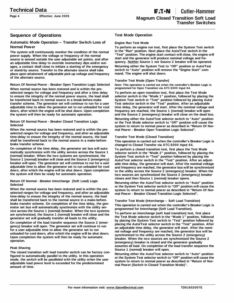
General DescriptionElectrical power generation located at or near the point of it’s con-sumption, commonly referred to as Distributed Generation, has seen tremendous growth recently due to factors such as limited utility grid generation and transmission capacity combined with the onset of utility deregulation. Strong economic incentives now exist for many users to consider on-site self generation for both improved power reliability and energy cost reduction. Additionally, these opportunities have spurred the development of new and unique types of generating and switching technologies.Eaton Closed Transition Soft Load Automatic Transfer Switches are just such a technology. Closed transition soft load transfer switches are an ideal solution for power availability, energy man-agement, and generator-set exercising applications. Unlike tradi-tional open transition switches that provide a break-before-make operation, the closed transition soft load switch allows two power sources, usually the utility and a generator set, to be paralleled indefinitely. This permits the load, inductive or resistive, to be gradually and seamlessly transferred from one source to another. All of this is accomplished through the make-before-break opera-tion of the switch with no power interruption to the load.Eaton Closes Transition Soft Load Switch utilizes an integrated microprocessor based power controller to make active paralleling of two power sources possible. It manages the speed governor and voltage regulator of the generator set to bring the two sources into synchronization. This approach allows the transfer switch to be applied in soft load transfer applications. In addition, it can also be used as a peak shaving switch helping customers to reduce their peak demand charges by paralleling the generator set with the utility source during times of high electrical demand.Standard fixed drawout or drawout bypass isolation configurations are available with or without an integral service entrance rating. If a switch with a service entrance rating is used as service entrance equipment, the need for separate service disconnects and overcur-rent protective devices is eliminated. Eaton Closed Transition Soft Load Automatic Transfer Switches are available for 800 through 3200 ampere, up to 600 Vac, 50 or 60 Hz applications worldwide. They are offered in both indoor (NEMA 1) and outdoor (NEMA 3R) free standing enclosures utiliz-ing drawout or fixed insulated case Magnum DS switching devices. The Magnum DS switching device is a 100% rated device with a 100 kA interrupting capability at 600 Vac.
ApplicationsPower reliability and power costs are two issues of strategic importance in almost all industry segments. Businesses have criti-cal processes that cannot tolerate a shut down, while an extended failure in many cases could cause unrecoverable losses. In addi-tion, significant changes in the utility industry have created on-site generation opportunities for customers to address their power reli-ability and energy cost concerns. This type of on-site power gen-eration at or near the point of consumption is known as distributed generation. Market studies estimate that over 40% of generation capacity added in the United States alone over the next 10 years will be distributed. A key enabler of these on-site generation sys-tems and reliable power in general is often a closed transition soft load transfer switch. Typical applications for Eaton Closed Transition Soft Load Auto-matic Transfer Switches include industrial processes, data centers and critical care facilities. Actually, any location with critical loads where the absence of power could result in lost revenue, produc-tion time, or personal injury should make this equipment a prime consideration.
Consider several specific applications:
• A facility with emergency or critical power systems wanting to test their generator sets without a power interruption.
• Any industrial, institutional, or commercial business seeking ways to lower energy costs by reducing demand charges, which can represent over 50% of an electrical bill.
• Energy Service Companies interested in offering performance based solutions to their customer base.
• Electrical power providers interested in offering power reliability solutions to their customer base in return for long term electrical contracts.
The Eaton Closed Transition Soft Load Automatic Transfer Switch can be applied in new installations or as a retrofit to replace an existing open transition transfer switch. A number of application issues should be reviewed. First, since most generator sets run on diesel fuel, there are exhaust emission concerns to consider. In some markets, the Environmental Protection Agency (EPA) limits the number of hours annually that a generator set can be oper-ated. Methods to deal with such restrictions, should they present a problem, are the use of natural gas or dual fuel (natural gas/die-sel mixture) types of generator sets. A second issue relates to electrical utility interconnection standards. Many utility companies require multiple levels of protective relaying when a user wishes to parallel to the utility grid. The cost of meeting some of these spec-ifications can be high. These issues should be discussed when peak shaving is being considered.
TD01602007E For more information visit: www.EatonElectrical.com
Technical DataPage 4 Effective: June 2005 Magnum Closed Transition Soft Load
Transfer Switches
Sequence of OperationsAutomatic Mode Operation – Transfer Switch Loss of Normal PowerThe system will continuously monitor the condition of the normal power supply. When the voltage or frequency of the normal source is sensed outside the user adjustable set points, and after an adjustable time delay to override momentary dips and/or out-ages, a contact shall close to initiate a starting of the emergency or stand-by source. Transfer to the alternate source shall take place upon attainment of adjustable pick-up voltage and frequency of the alternate source.
Return Of Normal Power - Breaker Open Transition Logic SelectedWhen normal source has been restored and is within the pre-selected ranges for voltage and frequency and after a time delay to ensure the integrity of the normal power source, the load shall be transferred back to normal source in a break-before-make transfer scheme. The generator set will continue to run for a user adjustable time to allow the generator set to run unloaded for cool down, after which the engine will be shut down. Upon completion the system will then be ready for automatic operation.
Return Of Normal Power - Breaker Closed Transition Logic SelectedWhen the normal source has been restored and is within the pre-selected ranges for voltage and frequency, and after an adjustable time-delay to ensure the integrity of the normal source, the load shall be transferred back to the normal source in a make-before-brake transfer scheme. On completion of the time delay, the generator set bus will auto-matically synchronize with the utility service across the Source 1 (normal) breaker. When the two systems are synchronized, the Source 1 (normal) breaker will close and the Source 2 (emergency) breaker will open. The generator set will continue to run for a user adjustable time to allow the generator set to run unloaded for cool down, after which the engine will be shut down. Upon completion the system will then be ready for automatic operation.
Return Of Normal - Breaker Interchange (Soft Load) Logic SelectedWhen the normal source has been restored and is within the pre-selected ranges for voltage and frequency, and after an adjustable time-delay to ensure the integrity of the normal source, the load shall be transferred back to the normal source in a make-before-brake transfer scheme. On completion of the time delay, the gen-erator set bus will automatically synchronize with the utility ser-vice across the Source 1 (normal) breaker. When the two systems are synchronized, the Source 1 (normal) breaker will close and the generator set will gradually transfer all loads to the utility.On completion of the load transfer sequence the Source 2 (emer-gency) breaker will open. The generator set will continue to run for a user adjustable time to allow the generator set to run unloaded for cool down, after which the engine will be shut down. Upon completion the system will then be ready for automatic operation.
Peak Shaving The closed transition soft load transfer switch can be factory con-figured to automatically parallel to the utility. In this operation mode, the switch will be paralleled with the utility when the user adjustable load power level is exceeded for the predetermined amount of time.
Test Mode Operation
Engine Run Test ModeTo perform an engine run test, first place the System Test switch in the “Run” position. Next place the Auto/Test switch in the “Test” position. The engine start contact will close, the engine will start and the generator will produce nominal voltage and fre-quency. Neither Source 1 nor Source 2 breaker will be operated. Returning either the System Test to “Off” position or Auto/Test switch to “Auto” position will remove the “Engine Start” com-mand. The engine will shut down.
Transfer Test Mode (Open Transfer)Note: This operation is carried out when the controller’s Breaker Logic is programmed for Open Transition via ATC-5000 Input 64.
To perform an open transition test, first place the Test Mode selector switch in the “Mode 1” position, followed by placing the System Test switch in “Test” position followed by placing Auto/Test selector switch in the “Test” position. After an adjustable time delay, the generator will start. After the nominal voltage and frequency are reached, the Source 1 (normal) breaker will open and the Source 2 (emergency) breaker will close on the dead bus.Returning either the Auto/Test selector switch to “Auto” position or the Test Mode selector switch to “Off” position will cause the system to return to normal power as described in “Return Of Nor-mal Power - Breaker Open Transition Logic Selected”.
Transfer Test Mode (Closed Transition)This operation is carried out when the controller’s Breaker Logic is changed to Closed Transfer via ATC-5000 Input 64.To perform a closed transition test, first place the Test Mode selector switch in the “Mode 2” position, followed by placing the System Test switch in “Test” position followed by placing the Auto/Test selector switch in the “Test” position. After an adjust-able time delay, the generator will start. After the nominal voltage and frequency are reached, the generator bus will be synchronized to the utility across the Source 2 (emergency) breaker. When the two sources are synchronized the Source 2 (emergency) breaker closes and then Source 1 (normal) breaker opens.Returning either the Auto/Test selector switch to “Auto” position or the System Test selector switch to “Off” position will cause the system to return to normal power as described in “Return Of Nor-mal Power - Breaker Closed Transition Logic Selected”.
Transfer Test Mode (Interchange – Soft Load Transition)This operation is carried out when the controller’s Breaker Logic is programmed for Interchange (Soft Load Transition).To perform an interchange (soft load transition) test, first place the Test Mode selector switch in the “Mode 1” position, followed by placing the System Test switch in “Test” position followed by placing the Auto/Test selector switch in the “Test” position. After an adjustable time delay, the generator will start. After the nomi-nal voltage and frequency are reached, the generator bus will be synchronized to the utility across the Source 2 (emergency) breaker. When the two sources are synchronized the Source 2 (emergency) breaker is closed and the generator gradually assumes all load. On completion of the load transfer sequence the Source 1 (normal) breaker will open.Returning either the Auto/Test selector switch to “Auto” position or the System Test selector switch to “Off” position will cause the system to return to normal power as described in “Return of Nor-mal Power (Switch in Closed Transition Mode)”.
For more information visit: www.EatonElectrical.com TD01602007E

Technical DataEffective: June 2005 Page 5
Magnum Closed Transition Soft LoadTransfer Switches
Paralleling Test mode (Baseload)This operation is carried out when the controller’s Breaker Logic is changed to Parallel via ATC-5000 Input 64 and the Baseload oper-ation is selected.To perform a paralleling test in a base load mode, first place the Test Mode selector switch in the “Mode 2” position, followed by placing the System Test switch in “Test” position followed by placing the Auto/Test selector switch in the “Test” position. After an adjustable time delay, the generator will start. After the nomi-nal voltage and frequency are reached, the generator bus will be synchronized to the utility across the Source 2 (emergency) breaker. When the two sources are synchronized the Source 2 (emergency) breaker is closed and the generator gradually assumes load up to the user programmable power level and then continuously maintains its power output. Returning either the Auto/Test selector switch to “Auto” position or the System Test selector switch to “Off” position will cause the generator to gradually unload and then the Source 2 (emergency) breaker will open. The generator set will continue to run for a user adjustable time allowing the generator set to run unloaded for cool down, after which the engine will be shut down. Upon completion the system will then be ready for automatic operation.
Paralleling Test Mode (Import/Export)This operation is carried out when the controller’s Breaker Logic is changed to Parallel (via ATC-5000 Input 64 and the Import/Export operation is selected.To perform a paralleling test in Import/Export mode, first place the Test Mode selector switch in the “Mode 2” position, followed by placing the System Test switch in “Test” position followed by placing the Auto/Test selector switch in the “Test” position. After an adjustable time delay, the generator will start. After the nomi-nal voltage and frequency are reached, the generator bus will be synchronized to the utility across the Source 2 (emergency) breaker. When the two sources are synchronized the Source 2 (emergency) breaker is closed and the generator gradually assumes load up to the user programmable import (adjustable power setting for power supplied from the utility) or export (adjustable power setting for power supplied to the utility) power level and then continuously varies its power output to maintain the selected power flow. Returning either the Auto/Test selector switch to “Auto” position or the System Test selector switch to “Off” position will cause the generator to gradually unload and then the Source 2 (emergency) breaker will open. The generator set will continue to run for a user adjustable time allowing the generator set to run unloaded for cool down, after which the engine will be shut down. Upon completion the system will then be ready for automatic operation.
Figure 1. Sequence Flow Chart – Soft Load ATS.
AUTO/TEST
Loss of NormalSource
Auto Test
Start Engine
Transfer Load toGenerator --Open
Transfer
Utility Returns
Transfer Load toUtility -- Soft
Transfer
Stop Engine afterCool Down
End
TEST MODE
Start Engine
Transfer Load toGenerator -- Soft
Transfer
Transfer Load toUtility -- Soft
Transfer
Stop Engine afterCool Down
End
SYSTEM TESTTest
Off
Run
Off Start Engine
Stop Engine
AUTO/TESTTestAuto*
End
Engine Continuesto Run
Breaker Logic -Interchange
(Soft Load/Unload)
Breaker Logic -Interchange
(Soft Load/Unload)
Start Engine
Transfer Load toGenerator --Open
Transfer
Transfer Load toUtility -- Open
Transfer
Stop Engine afterCool Down
End
Breaker Logic -Open Transfer
Start Engine
Transfer Load toGenerator --Closed
Transfer
Breaker Logic -Closed Transfer
Mode 1 Mode 2
OR
AUTO/TESTTestAuto*
Load Stays onGenerator
Transfer Load toUtility -- Closed
Transfer
Stop Engine afterCool Down
End
AUTO/TESTTestAuto*
Load Stays onGenerator
SynchronizeGenerator to Utility
AUTO/TESTTestAuto*
Load Stays onGenerator
SynchronizeGenerator to Utility
SynchronizeGenerator to Utility
SynchronizeGenerator to Utility
TD01602007E For more information visit: www.EatonElectrical.com

Technical DataPage 6 Effective: June 2005 Magnum Closed Transition Soft Load
Transfer Switches
Figure 2. Sequence Flow Chart - Soft Load ATS with Extended Paralleling Capabilities
AUTO/TEST
Loss of NormalSource
Auto Test
Start Engine
Transfer Load toGenerator --Open
Transfer
Utility Returns
Transfer Load toUtility -- Soft
Transfer
Stop Engine afterCool Down
End
TEST MODE
Start Engine
Transfer Load toGenerator -- Soft
Transfer
Transfer Load toUtility -- Soft
Transfer
Stop Engine afterCool Down
End
SYSTEM TESTTest
Off
Run
Off Start Engine
Stop Engine
AUTO/TESTTestAuto*
End
Engine Continuesto Run
Breaker Logic -Interchange
(Soft Load/Unload)
Breaker Logic -Interchange
(Soft Load/Unload)
Start Engine
Close theGenerator Breakerand Soft Load the
Generator
Soft Unload theGenerator and
Open the Source 2(Emergency)
Breaker
Stop Engine afterCool Down
End
Breaker Logic -Parallel (Baseload)
Start Engine
Breaker Logic -Parallel (Import/
Export)
Mode 1 Mode 2
OR
AUTO/TESTTestAuto*
Maintain BaseloadGenerator Power
Output
Stop Engine afterCool Down
End
AUTO/TESTTestAuto*
Maintain Import/Export Generator
Power Otput
SynchronizeGenerator to Utility
AUTO/TESTTestAuto*
Load Stays onGenerator
SynchronizeGenerator to Utility
SynchronizeGenerator to Utility
* - Or switch SYSTEM TEST selector switch to OFF
SynchronizeGenerator to Utility
Close the Source 2(Emergency)
Breaker and SoftLoad the Generator
Soft Unload theGenerator and
Open the Source 2(Emergency)
Breaker
For more information visit: www.EatonElectrical.com TD01602007E

Technical DataEffective: June 2005 Page 7
Magnum Closed Transition Soft LoadTransfer Switches
Technical SpecificationsSystem
StandardsEaton Soft Load ATSs are listed in File E38116 by UL, Inc., under Standard UL 1008. This standard covers requirements for ATSs intended for use in ordinary locations to provide for lighting and power as follows: a. In emergency systems, in accordance with articles 517 and
700 in the National Electrical Code (NEC), American National Standards Institute/National Fire Protection Association (ANSI/NFPA) 70 and the NFPA No. 76A and/or
b. In stand-by systems, in accordance with article 702 of the NEC and/or
c. In legally required stand-by systems in accordance with article 701 of the NEC.
Eaton ATSs are available to meet NFPA 110 for emergency and stand-by power systems, and NFPA 99 for health care facilities when ordered with the appropriate options.Since Eaton ATSs utilize specially designed switches and/or switching devices as the main power switching contacts, these devices must also be listed under the additional UL Standard 1066. UL utilizes two basic types of listing programs: a) Label Ser-vice and b) Re-examination. UL1066 employs a label service list-
ing program which requires an extensive follow-up testing pro-gram for listed devices. Standard UL1008 for ATSs lists devices under the re-examination program which only requires a continual physical re-examination of the components used in the product to insure consistency with the originally submitted device. Follow-up testing IS NOT required by UL1008.Representative production samples of switches and switching devices used in Eaton ATSs are subjected to a complete test pro-gram identical to the originally submitted devices on an ongoing periodic basis per UL1066. The frequency of such a re-submittal can be as often as every quarter for a low ampere device.
Environmental
Seismic With proper installation and by including Option 42 which includes specially designed cleats, the Magnum transfer switch is a Seis-mic Certified Transfer Switch with certificate for application that is Seismic Zone 4 under the California Building Code, the Uniform Building Code, and BOCA.
Operational Conditions Normal operation in an electrical equipment room for indoor appli-cations. Outdoor applications can subject units to falling rain, freezing temperatures, and 95% humidity (non condensing). Ambient temperature for operation is between -20 and +65°C (-4 and 149°F).
Table 1. System RatingsStandard UL 1008 3-Cycle 30-Cycle Extended Rating
ATS Ampere Rating
Ratings when used with upstream breaker (kA)
Ratings used for coordination with upstream breakers with short time rating
120 - 600 Vac 120 - 600 Vac
Magnum DS Fixed & Drawout
800 100 85
1000 100 85
1200 100 85
1600 100 85
2000 100 85
2500 100 85
3200 100 85
TD01602007E For more information visit: www.EatonElectrical.com

Technical DataPage 8 Effective: June 2005 Magnum Closed Transition Soft Load
Transfer Switches
Figure 3. Typical System Diagram – Standard One Line.
Figure 4. Typical System Diagram – Standard One Line With Utility Grade Multi-function Relaying.
SOURCE 23-CT 52-2
TO CUSTOMER LOADS
52-1 1-CT
Va, Vb, Vc Va, Vb, Vc
VM
AM
KWM
FM
27
59
32
32R
VM
AM
KWM
PFM
27
59
Va1a, 1b, 1c 1a
78
ATC-5000
25
1133
3
SOURCE 1
12
46
50
81O/U 81O/U
TVSS
32
46
51V
51N
27
47
59
60FL
59I
Va 1a, 1b, 1c
Va, V
b, V
c
SOURCE 23-CT
TO BUILDING LOADS
Va
SOURCE 1
1a, 1b, 1cVa, Vb, Vc
1aVa, Vb, Vc
ATC-5000
M-3410A
25
133
1133
3
52-2 52-1 1-CT 3-CT
VM
AM
KWM
FM
27
59
32
32R
VM
AM
KWM
PFM
27
59
78
2512
46
50
81O/U 81O/U
81
79
TVSS
CONTROLFUNCTION
For more information visit: www.EatonElectrical.com TD01602007E

Technical DataEffective: June 2005 Page 9
Magnum Closed Transition Soft LoadTransfer Switches
Base Components
Figure 5. Magnum Soft Load ATS Base Components.
EnclosureThe rugged steel switch enclosure is supplied with four door hinges, regardless of enclosure size, to insure proper support of the door and door mounted devices. The hinges have removable hinge pins to facilitate door removal. The doors are supplied as standard with thumbscrew and padlock latches. Cable entry holes are the customer’s responsibility. The door is used to mount a variety of lights, switches, and push buttons, depending upon the options required for a particular switch. All switch doors are supplied with a heavy duty plastic accessory panel in place, whether or not external devices are required. When lights, pushbuttons, or switches are required, they are normally mounted in the plastic door mounted panel.Transfer switch enclosures and some internal steel mounting plates, such as the transformer panel mounting plate, go through a pre-treatment cleaning system prior to painting to insure a dura-ble finish. Should the enclosure become scratched and in need of touch up paint, use ANSI 61. All remaining steel is galvanized.The standard switch enclosure is NEMA Type 1 for general indoor use (Table 2).
Table 2. Transfer Switch Equipment Enclosures
Power CablesPower cables are to be connected to solderless screw type lugs located on the transfer switch switching devices. Refer to the sep-arate Customer Wiring Diagrams supplied with the transfer switch equipment for power termination. Verify that the lugs supplied will accommodate the power cables being used. Also verify that the cables comply with local electrical codes. Standard transfer switch equipment, as supplied from the factory, will accommo-date the wire sizes shown in Table 3.
Table 3. Wire Size for Available Power Cable Connections
Table 4. Dimensions Chart
Logic Panel
Customer Connections
Source 2 Magnum DSBreaker
Transformer Panel
Source 1 Magnum DSBreaker
Breaker Status Lights
ATC-5000 Controller
Device Panel
Service Entrance Device Panel
Utility Grade Metering
TVSS
Protective Relay
NEMA TYPE DESIGN PROTECTION
1 Indoor Enclosed Equipment
3R Outdoor Rain, Ice Formation
Device Switch Rating (Amps) Cables per Phase Range Wiring Size
Switch 800 - 2000 6 3/0 - 750 MCM
Switch 2500 - 3200 9 3/0 - 750 MCM
Neutral 800 - 2000 24 4/0 - 500 MCM
Neutral 2500 - 3200 36 4/0 - 500 MCM
Dimensions
Design Amperes Poles H (in.) W (in.) D(in.) H (in.) W (in.) D (in.)
NEMA 1 NEMA 3R
Fixed 800-20002500-3200
3&43&4
9090
3244
4848
9090
3244
5454
Drawout 800-20002500-3200
3&43&4
9090
3244
6060
9090
3244
6666
Fixed With Bypass Isolation 800-20002500-3200
3&43&4
9090
6488
4848
9090
6488
5454
Drawout With Bypass Isolation 800-20002500-3200
3&43&4
9090
6488
6060
9090
6488
6666
TD01602007E For more information visit: www.EatonElectrical.com

Technical DataPage 10 Effective: June 2005 Magnum Closed Transition Soft Load
Transfer Switches
Transfer Switch Catalog Number Identification Transfer switch equipment catalog numbers provide a significant amount of relevant information that pertains to a particular piece of equipment. The catalog number identification table (Table 5) provides the required interpretation information. An example for an open transition switch is offered to initially simplify the pro-cess.
Example: Catalog Number (circled numbers correspond to position headings in Table 5).
The catalog number CTVCMGE32000XRU describes a Soft Load ATS with the drawout switching devices mounted vertically in the enclosure. The intelligence, represented by the ATC-5000, is a microprocessor-based logic package. The Magnum Breaker is used as the switching device and is a 3-pole molded case breaker for each source. The continuous current rating of this equipment is 2000 A and is applicable at 480/277 Vac, 60 Hz. The transfer switch equipment is enclosed in a NEMA 3R enclosure and is listed for Underwriters Laboratories (UL).
Table 5. Transfer Switch Catalog Number Explanation.
CT V C MG E 3 2000 X R U
1 to 2 3 4 5 6 7 8 9 to 12 13 14 15to
CT V C G E 3 2 0 0 0 RX UM
TY
PE
OR
IEN
TAT
ION
LOG
IC
FR
AM
E
SW
ITC
H
PO
LES
AM
PE
RE
RAT
ING
VO
LTA
GE
EN
CLO
SU
RE
TY
PE
LIS
TIN
G
LOGICPosition 4C = ATC 5000
TYPEPosition 1-2CT = Closed Transition
ORIENTATIONPosition 3V = Vertical
FRAMEPosition 5-6Molded CasesMagnum DS MG
SWITCHPosition 7A = Fixed Mount, Molded Case Switch (MCS Both)B = Fixed Mount, Molded Case Circuit Breaker (HCCB Both)C = Fixed Mount, MCCB Normal, MCS EmergencyD = Fixed Mount, MCS Normal, MCCB EmergencyE = Drawout, MCS BothF = Drawout, MCCB BothG = Drawout, MCCB Normal, MCS EmergencyH = Drawout, MCS Normal, MCCB Emergency
POLESPosition 83 = 3 Poles4 = 4 Poles
AMPERESPosition 9-120800 = 800A1000 = 1000A1200 = 1200A1600 = 1600A2000 = 2000A2500 = 2500A3200 = 3200A
ENCLOSUREPosition 14S = NEMA 1R = NEMA 3R
LISTINGPosition 15U = UL Listed
VOLTAGEPosition 13A = 120 V 60 Hz 3 Phase 3 WireB = 208/120 60 Hz 3 Phase 4 WireE = 600 V 60 Hz 3 Phase 3 WireE = 600 V 60 Hz 3 Phase 4 WireG = 220/127 V 50 Hz 3 Phase 4 WireG = 220/110 V 50/60 Hz 1 Phase 3 WireH = 380/220 V 50 Hz 3 Phase 4 WireK = 600 V 50 Hz 3 Phase 4 WireM = 230 V 50 Hz 3 Phase 3 WireM = 230 V 50 Hz 1 Phase 3 WireN = 401/230 V 50 Hz 3 Phase 4 WireO = 415/240 V 50 Hz 3 Phase 4 WireW = 240/120 V 60 Hz 1 Phase 3 WireW = 240 V 60 Hz 3 Phase 3 WireW = 240/120 V 60 Hz 3 Phase 4 Wire Hi-LegW = 230/115 V 60 Hz 1 Phase 3 WireX = 480 V 60 Hz 3 Phase 3 WireX = 480/277 V 60 Hz 3 Phase 4 WireX = 480/240 V 50 Hz 1 Phase 2 WireZ = 346/220 V 50 Hz 3 Phase 4 Wire
Magnum Soft LoadTransfer Switches 800-3200 Amperes
USING THE STYLE IDENTIFICATION GUIDE The Style Identification Guide provides an overview of the ten basic style/feature categories which generate the 15 digit catalog number.
For more information visit: www.EatonElectrical.com TD01602007E

Technical DataEffective: June 2005 Page 11
Magnum Closed Transition Soft LoadTransfer Switches
ATS-5000 Integrated Microprocessor Controller
The integrated logic controller is a microprocessor-based generator set control and management package. ATC-5000 provides a user-friendly interface allowing operators to easily view system status, view and reset alarms, display metered values and modify device setpoints.The unit provides fully integrated communication to engine Elec-tronic Control Units (ECUs) including:• [via CAN bus] standard SAE J1939, Deutz EMR, Scania S6,
mtu MDEC;• [via RS232] Caterpillar CCM to EMCP-II, and ECM.
Features include:• Integrated LED display• Automatic Transfer Switch Logic• True RMS sensing• Frequency and Voltage Bias Outputs for the generator sets• Protective Relays
– Device 25A Synchronizer– Device 59/27 O/U Voltage for generator set and utility tie– Device 81 O/U Frequency for generator set and utility tie– Device 78 Phase/Vector shift for the utility tie– Device 32/32R Overload/Reverse Power for the generator
set– Device 46 Load Imbalance for the generator set– Device 50/51 Over-current for the generator set
• Load Management– Automatic base load/peak shaving– Import/Export power control
• Automatic Start/Stop sequencing for gas and diesel engines• Load dependent start/stop• Real Power / PF control• Counters for kWh, engine starts, operating hours and mainte-
nance call• Freely configurable discrete and analog alarm inputs• Freely configurable relay and analog outputs• Language Manager• Event Logging• PC and front panel configurable
• Multi level password protection• Battery voltage monitoring• CAN bus communication
Specifications Accuracy................................................................... Class 1Power supply ..................................12/24 Vdc (9.5 to 32 Vdc)Intrinsic consumption.............................................Max. 20 WAmbient temperature ........................................... -20 to 70°CAmbient humidity ..................................95 %, non-condensingVoltage Rated (Vrated): [1] 69/120 Vac or [4] 231/400 Vac
UL: [1]max.86/150 Vac or [4]max.173/300 VacSetting range(sec.)star: [1]50 to 125 Vac or [4]50 to 480 VacSetting range(sec.)delta: [1]50 to 114 Vac or [4]50 to 380 VacSetting range(prim.): 0.050 to 65,000 kVacMeasuring frequency............................. 50/60 Hz (40 to 70 HzLinear measuring range up to ............................... 1.3 × VratedInput resistance.................................. [1] 0.21 MΩ, [4] 0.7 MΩMax. power consumption per path.............................<0.15 WCurrent (rated values; Irated) ................. [../1]../1A or [../5]../5ACurrent-carrying capacity...............................Igen=3.0 × Irated
Imains=1.5 × IratedLoad .....................................................................<0.15 VARelated short-time current (1s) ... [../1]50×Irated,[../5] 10 × IratedDiscrete inputs ........................................................... isolatedInput range ........................................12/24 Vdc (6 to 32 Vdc)Input resistance...............................................Approx. 6.8 kΩAnalog inputs..................................................Freely scaleableType............................................. 0/4 to 20 mA, Pt100, VDOResolution .................................................................. 10 BitRelay outputs..................................................... Potential freeContact material..........................................................AgCdOLoad (GP) ................................................ 2.00 Aac@250 Vac
2.00 Adc@24 Vdc/0.36 Adc@125 Vdc/0.18 Adc@250 VdcPilot duty (PD)............................................................... B300
1.00 Adc@24 Vdc/0.22 Adc@125 Vdc/0.10 Adc@250 VdcAnalog outputs ..........................................................IsolatedType..........................................0/4 to 20mA, freely scaleableResolution ................................. 8/12 Bit (depending on model)Max. load 0/4-20 mA....................................................500 ΩInsulating voltage ...................................................1,500 VdcHousing ....................................Type APRANORM DIN 43 700Dimensions.............................................144 × 144 × 118 mmFront cutout ................................ 138[+1.0] × 138(+1.0] mmConnection .............................. Screw/plug terminals depending
on connector 1.5 mm2 or 2.5 mm2
Front .......................................................... Insulating surfaceProtection system................................. With proper installation
Front............................................. IP42(sealed IP45; gasket kit=P/N 8923-1039)
Back..............................................IP21Weight ...........................Depending on version, approx. 1,000gDisturbance test(CE) ......... Tested according to applicable EN guidelinesListings .........................UL/cUL listed (voltages up to 300 Vac)
TD01602007E For more information visit: www.EatonElectrical.com

Technical DataPage 12 Effective: June 2005 Magnum Closed Transition Soft Load
Transfer Switches
Optional Components
Metering
Figure 6. IQ AnalyzerHighly accurate source or load metering can be provided for advanced energy management and power quality analysis. Meet-ing the stringent ANSI C12.16 Class 10 accuracy requirement, Eaton IQ Analyzer meter can measure parameters including volt-age, current, power (watts, vars and VA), energy, frequency, demand, power factor, %THD (voltage and current), K factor, CBEMA derating factor and crest factor. IQ Analyzer can also communicate with Eaton's industry accepted IMPACC and Power-NetTM Power Management Systems. (See Eaton TD 17530, avail-able on line, for more information.)
Protective Relaying
Figure 7. Protective RelayFor paralleling (including soft loading / unloading) applications, util-ity grade protective relaying is optional, and offered when utility interconnection standard requires additional protection on top of that provided by ATC-5000 controller. The following protective relays can be included in Eaton Soft Load ATS: • Beckwith M-3410A - See Appendix B for details.• Beckwith M-3520• Schweitzer SEL-351• Schweitzer SEL-547• Basler BE1-951• Basler BE1-IPS100All above protective relays provide protection necessary to satisfy IEEE P1547 standard "IEEE Standard for Interconnecting Distrib-uted Resources with Electric Power Systems". See Table 6.
Table 6. Protective Relays
1 - Generator Protective Feature S - Standard Function2 - Utility Protective Feature O - Optional Function
Utility Intertie Protection
ANSI/IEEENumber
Function ATC-5000 Eaton Digitrip(Optional)
BeckwithM-3410A(Optional)
BeckwithM-3520(Optional)
SchweitzerSEL-547(Optional)
SchweitzerSEL-351(Optional)
BaslerBE1-951(Optional)
BaslerBE1-IPS100(Optional)
21 Phase Distance O
24 Overexcitation V/Hz S S
25 Synchronizer S
Synch Check S S S S S S
27 Undervoltage S1,2 S S S S S S
27G Ground Undervoltage S O
32 Reverse/Forward Power S1 S S S S S S
40 Loss-of-Field S
46 Negative Sequence Overcurrent S1 S S
47 Negative Sequence Overvoltage S S S S S
50 Instantaneous Phase Overcurrent S1 S1,2 S S S S
50N Instantaneous Ground Overcurrent O1,2 S S S S
51 AC Time Overcurrent S1 S1,2 S S S
51N AC Time Ground Overcurrent O1,2 S S S S S
51V Voltage Restrained Overcurrent S S S
59 Overvoltage S1,2 S S S S S S
59G Ground Overvoltage S O S
59I Peak Overvoltage S O
60FL VT Fuse-Loss Detection S S S S
62 General Purpose Timers S
67 Phase Directional Overcurrent S S S
67N Residual Directional Overcurrent O S
72 Phase/Vector Shift S2
79 Reconnect Enable Time Delay S S S S
81 O/U Over/Under Frequency S1,2 S S S S S S
81R Rate of Change of Frequency O S
For more information visit: www.EatonElectrical.com TD01602007E

Technical DataEffective: June 2005 Page 13
Magnum Closed Transition Soft LoadTransfer Switches
Transient Voltage Surge SuppressionEaton's Clipper Power System -VisorTM series transient voltage surge suppression (TVSS) components can be integrated into any closed transition soft load switch. Surge current ratings 100 kA, 160 kA, and 200 kA per phase provide a range of cost effective facility-wide protection solutions. Status indication on each phase is standard with any TVSS option. Metering and communication capabilities are also available. See Appendix C for details.
CommunicationsOptional communication capability via Communication Gateway is available allowing remote data access, control, programming, sys-tem interface and dispatch.
System InterfaceA system control panel provides user-friendly interface to the closed transition soft load controller, allowing operators to easily monitor the switching devices position and manually test genera-tor and the system operations.Switching Devices Status Lights• Source 1 Open (Green)• Source 1 Closed (Red)• Source 1 Trip (Amber)• Source 2 Open (Green)• Source 2 Closed (Red)• Source 2 Trip (Amber)Front Panel Control Switches and LightsThe combination of the following pilot devices can be imple-mented on the unit:• AUTO/TEST Switch• SYSTEM TEST Switch• TEST MODE Switch• ALARM SILENCE Switch • READY FOR OPERATION Lamp (White) - verifies the ATC-5000
status
Magnum DS Switch FeaturesUL 489 and UL1008 listed• 85 – 100 KA standard withstand ratings• 30-cycle, extended withstand rating• Five-cycle closing speed• Electrically and/or manually operated• True 4 pole switched neutral availability• Totally enclosed contact assembly• Fixed mount and DO designs available
Optional Intergral Overcurrent Protection CapabilityFor service entrance applications, Digitrip microprocessor-based trip units can be integrated into the power switching devices. This eliminates the need for the separate upstream protective device, saving installation cost and space. Available with various combi-nations of Long, Short, Instantaneous and Ground Fault Protec-tion, Digitrips can communicate with Eaton’s IMPACC and PowerNetTM Power Management Systems.
Optional On-board 24 Vdc Power SupplyOn-board 24 Vdc power supply circuit, consisting of two (2) 12Vdc gel-cell UPS type batteries and battery charger, is available on the unit to provide DC control power to soft load transfer switch components. Engine battery can be connected in the “best battery” circuit as well, further improving the system’s reliability.
Optional FeaturesService EntranceWhen the transfer switch is applied as a service equipment device, the need for separate service disconnects and overcurrent protective devices is eliminated. Refer to the Service Entrance Application illustration.This optional feature provides the transfer switch as suitable for a service equipment rating. A key operated selector switch permits external power operated service disconnection with a pilot light providing external indication of the disconnect. The option is avail-able with or without ground fault protection. Integral overcurrent protection is provided by means of the power switching device.
Installation Comparison
Conventional Method...• UL 1008 Listed ATS• Separate Generator Breaker• Separate Generator Breaker Enclosure• Separate Service Disconnect• Separate Service Disconnect Enclosure• Power Cable/Bus Interconnections• Installation of the Separate Components• Extra Space Requirement• dded Maintenance Requirement
Cutler-Hammer Method...
• ATS with Service Equipment Features• UL 1008 Listed for Service Equipment• Service Disconnect “both-off” Capability• Integral Overcurrent Protection• Lockout (When in disconnect position only)• Indication of Service Disconnect• Integrated Design• Disconnecting Neutral Assembly• Ground Fault Protection Capability–All Ratings (Required by
code on ratings 480V and 1000A or higher)
ServiceDisconnect
Utility Service
GeneratorBreaker
Generator
Load
ATS
G
ServiceDisconnect
Utility Service
GeneratorBreaker
Generator
Load
ATS
G
TD01602007E For more information visit: www.EatonElectrical.com

Technical DataPage 14 Effective: June 2005 Magnum Closed Transition Soft Load
Transfer Switches
Table 7. OptionsService Entrance Rating
16n Overcurrent Protection - Normal
16e Overcurrent Protection - Emergency
16b Overcurrent Protection - Both
37a Service Entrance
37b Service Entrance w/ Ground Fault
Metering
18o IQ Analyzer - Normal
18p IQ Analyzer - Emergency
18q IQ Analyzer - N/E Selectable
18u IQ Analyzer - Load
Plant Exerciser
23j Automatic 24hrs/7days Selectable Load/No Load
Expanded Controller I/O
25a Additional Discrete and Analog I/O for Genset Control and Monitoring
Space Heater and Thermostat
41c 400 W Heater w/Thermostat
Surge Protection
51m4b Engine Control (24Vdc) Surge Device
51na1 100kA Surge Device w/AdVisor Source 1
51ns1 100kA Surge Device w/SuperVisor Source 1
51nn1 100kA Surge Device w/NetVisor Source 1
51qa1 160kA Surge Device w/AdVisor Source 1
51qs1 160kA Surge Device w/SuperVisor Source 1
51qn1 160kA Surge Device w/NetVisor Source 1
51sa1 200kA Surge Device w/AdVisor Source 1
51ss1 200kA Surge Device w/SuperVisor Source 1
51sn1 200kA Surge Device w/NetVisor Source 1
On-Board 24 VDC Power Supply
24c Battery Charger and Gell-Cell Batteries
Protective Devices
53a Beckwith M-3410A
53b Schweitzer SEL-547
53c Basler BE1-951
53d Beckwith M-3520
53e Schweitzer SEL-351
53f Basler BE1-IPS100
Communication
54b External Communication Gateway
54c Serial Modbus over Ethernet
Field Start-up
56a 2-day Start-up (Includes 1 day for travel)
For more information visit: www.EatonElectrical.com TD01602007E

Technical DataEffective: June 2005 Page 15
Magnum Closed Transition Soft LoadTransfer Switches
Appendix A
Table A-1. kW to Ampere Conversion Chart
➀ At 0.8 Power Factor.
Three-Phase Ampere Table at Common Line-to-Line Voltage
kW➀ 200V 208V 220V 230V 240V 380V 400V 415V 460V 480V 600V
5.07.5
10.0
182736
172634
162533
162431
152330
91419
91318
91317
81216
81115
69
12
15.020.025.0
547290
526987
496682
476378
456075
283847
273645
263543
243139
233038
182430
30.040.050.0
108144180
104139173
98131164
94126157
90120150
577695
547290
527087
476378
456075
364860
60.075.080.0
217271289
208260278
197246262
188235251
180226241
114142152
108135144
104130139
94118126
90113120
729096
100.0125.0150.0
361451541
347434520
328410492
314392471
301376451
190237285
180226271
174217261
157196235
150188226
120150180
175.0200.0250.0
631722902
607694867
574656820
549628784
526601752
332380475
316361451
304348435
275314392
263301376
210241301
300.0350.0400.0
108312631443
104112141388
98411481312
94110981255
90210521203
570665760
541631722
522609696
471549628
451526601
361421481
500.0600.0700.0
180421652526
173520822429
164019682296
156918832197
150418042105
95011401329
90210831263
87010431217
784941
1098
752902
1052
601722842
800.0900.0
1000.0
288732483609
277631233470
262429523280
251028243138
240627063007
151917091899
144316241804
139115651739
125514121569
120313531503
96210831203
TD01602007E For more information visit: www.EatonElectrical.com
Technical DataPage 16 Effective: June 2005 Magnum Closed Transition Soft Load
Transfer Switches
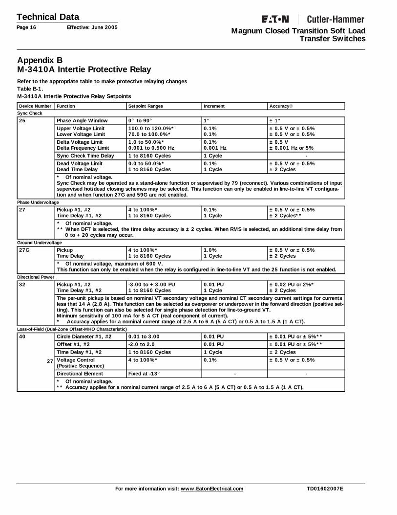
Appendix BM-3410A Intertie Protective Relay Refer to the appropriate table to make protective relaying changesTable B-1. M-3410A Intertie Protective Relay Setpoints
Device Number Function Setpoint Ranges Increment Accuracy➁
Sync Check
25 Phase Angle Window 0° to 90° 1° ±1°Upper Voltage LimitLower Voltage Limit
100.0 to 120.0%*70.0 to 100.0%*
0.1%0.1%
±0.5 V or ±0.5%±0.5 V or ±0.5%
Delta Voltage LimitDelta Frequency Limit
1.0 to 50.0%*0.001 to 0.500 Hz
0.1%0.001 Hz
±0.5 V±0.001 Hz or 5%
Sync Check Time Delay 1 to 8160 Cycles 1 Cycle -Dead Voltage LimitDead Time Delay
0.0 to 50.0%*1 to 8160 Cycles
0.1%1 Cycle
±0.5 V or ±0.5%±2 Cycles
* Of nominal voltage.Sync Check may be operated as a stand-alone function or supervised by 79 (reconnect). Various combinations of input supervised hot/dead closing schemes may be selected. This function can only be enabled in line-to-line VT configura-tion and when function 27G and 59G are not enabled.
Phase Undervoltage
27 Pickup #1, #2Time Delay #1, #2
4 to 100%*1 to 8160 Cycles
0.1%1 Cycle
±0.5 V or ±0.5%±2 Cycles**
* Of nominal voltage.** When DFT is selected, the time delay accuracy is ±2 cycles. When RMS is selected, an additional time delay from
0 to +20 cycles may occur.Ground Undervoltage
27G PickupTime Delay
4 to 100%*1 to 8160 Cycles
1.0%1 Cycle
±0.5 V or ±0.5%±2 Cycles
* Of nominal voltage, maximum of 600 V.This function can only be enabled when the relay is configured in line-to-line VT and the 25 function is not enabled.
Directional Power
32 Pickup #1, #2Time Delay #1, #2
-3.00 to +3.00 PU1 to 8160 Cycles
0.01 PU1 Cycle
±0.02 PU or 2%*±2 Cycles
The per-unit pickup is based on nominal VT secondary voltage and nominal CT secondary current settings for currents less that 14 A (2.8 A). This function can be selected as overpower or underpower in the forward direction (positive set-ting). This function can also be selected for single phase detection for line-to-ground VT.Mininum sensitivity of 100 mA for 5 A CT (real component of current).* Accuracy applies for a nominal current range of 2.5 A to 6 A (5 A CT) or 0.5 A to 1.5 A (1 A CT).
Loss-of-Field (Dual-Zone Offset-MHO Characteristic)
40
27
Circle Diameter #1, #2 0.01 to 3.00 0.01 PU ±0.01 PU or ±5%**Offset #1, #2 -2.0 to 2.0 0.01 PU ±0.01 PU or ±5%**Time Delay #1, #2 1 to 8160 Cycles 1 Cycle ±2 CyclesVoltage Control(Positive Sequence)
4 to 100%* 0.1% ±0.5 V or ±0.5%
Directional Element Fixed at -13° - -* Of nominal voltage.** Accuracy applies for a nominal current range of 2.5 A to 6 A (5 A CT) or 0.5 A to 1.5 A (1 A CT).
For more information visit: www.EatonElectrical.com TD01602007E
Technical DataEffective: June 2005 Page 17
Magnum Closed Transition Soft LoadTransfer Switches
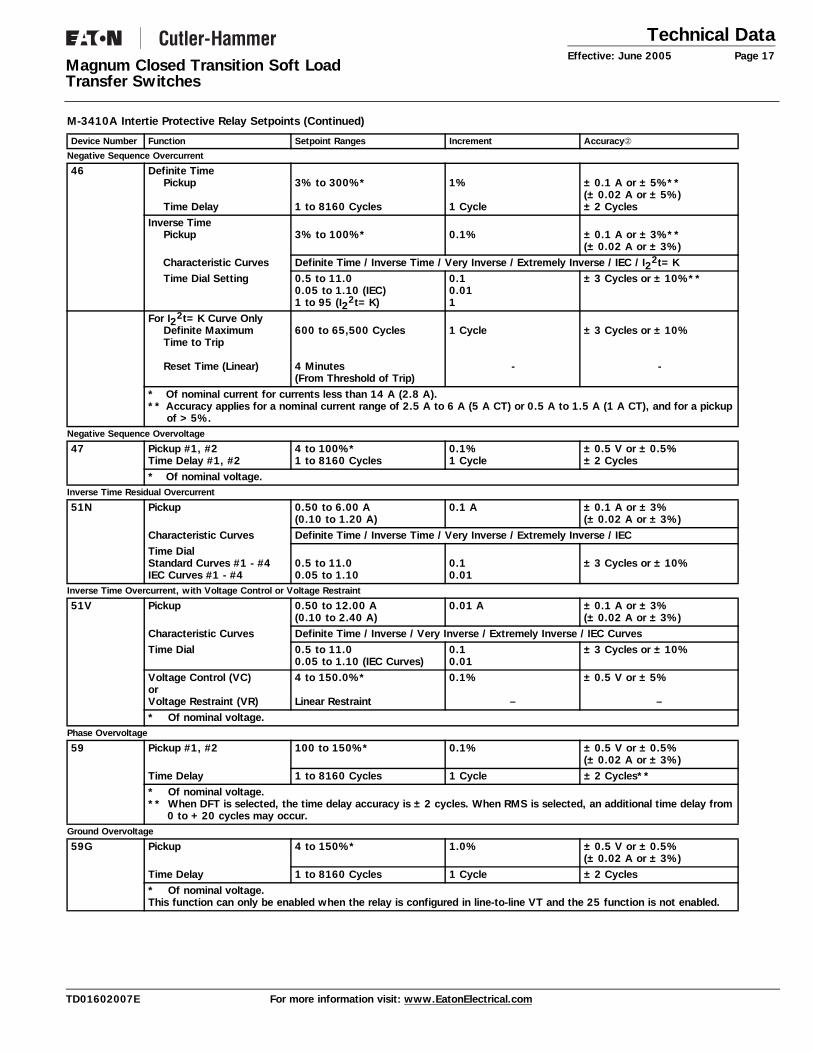
Negative Sequence Overcurrent
46 Definite TimePickup
Time Delay
3% to 300%*
1 to 8160 Cycles
1%
1 Cycle
±0.1 A or ±5%**(±0.02 A or ±5%)±2 Cycles
Inverse TimePickup 3% to 100%* 0.1% ±0.1 A or ±3%**
(±0.02 A or ±3%)Characteristic Curves Definite Time / Inverse Time / Very Inverse / Extremely Inverse / IEC / I22t=KTime Dial Setting 0.5 to 11.0
0.05 to 1.10 (IEC)1 to 95 (I22t=K)
0.10.011
±3 Cycles or ±10%**
For I22t=K Curve Only
Definite MaximumTime to Trip
Reset Time (Linear)
600 to 65,500 Cycles
4 Minutes(From Threshold of Trip)
1 Cycle
-
±3 Cycles or ±10%
-
* Of nominal current for currents less than 14 A (2.8 A).** Accuracy applies for a nominal current range of 2.5 A to 6 A (5 A CT) or 0.5 A to 1.5 A (1 A CT), and for a pickup
of >5%.Negative Sequence Overvoltage
47 Pickup #1, #2Time Delay #1, #2
4 to 100%*1 to 8160 Cycles
0.1%1 Cycle
±0.5 V or ±0.5%±2 Cycles
* Of nominal voltage.Inverse Time Residual Overcurrent
51N Pickup 0.50 to 6.00 A(0.10 to 1.20 A)
0.1 A ±0.1 A or ±3%(±0.02 A or ±3%)
Characteristic Curves Definite Time / Inverse Time / Very Inverse / Extremely Inverse / IECTime DialStandard Curves #1 - #4IEC Curves #1 - #4
0.5 to 11.00.05 to 1.10
0.10.01
±3 Cycles or ±10%
Inverse Time Overcurrent, with Voltage Control or Voltage Restraint
51V Pickup 0.50 to 12.00 A(0.10 to 2.40 A)
0.01 A ±0.1 A or ±3%(±0.02 A or ±3%)
Characteristic Curves Definite Time / Inverse / Very Inverse / Extremely Inverse / IEC CurvesTime Dial 0.5 to 11.0
0.05 to 1.10 (IEC Curves)0.10.01
±3 Cycles or ±10%
Voltage Control (VC) orVoltage Restraint (VR)
4 to 150.0%*
Linear Restraint
0.1%
–
±0.5 V or ±5%
–* Of nominal voltage.
Phase Overvoltage
59 Pickup #1, #2 100 to 150%* 0.1% ±0.5 V or ±0.5%(±0.02 A or ±3%)
Time Delay 1 to 8160 Cycles 1 Cycle ±2 Cycles*** Of nominal voltage.** When DFT is selected, the time delay accuracy is ±2 cycles. When RMS is selected, an additional time delay from
0 to +20 cycles may occur.Ground Overvoltage
59G Pickup 4 to 150%* 1.0% ±0.5 V or ±0.5%(±0.02 A or ±3%)
Time Delay 1 to 8160 Cycles 1 Cycle ±2 Cycles* Of nominal voltage.This function can only be enabled when the relay is configured in line-to-line VT and the 25 function is not enabled.
M-3410A Intertie Protective Relay Setpoints (Continued)
Device Number Function Setpoint Ranges Increment Accuracy➁
TD01602007E For more information visit: www.EatonElectrical.com
Technical DataPage 18 Effective: June 2005 Magnum Closed Transition Soft Load
Transfer Switches
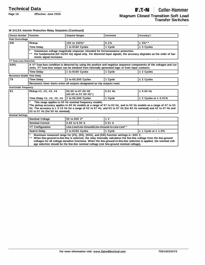
Peak Overvoltage
59I Pickup 100 to 150%* 0.1% ±3%**Time Delay 1 to 8160 Cycles 1 Cycle ±3 Cycles* Instaneous voltage magnitude response; intended for ferroresonance protection.** For fundamental (60 Hz/50 Hz) signal only. For distorted input signals, the accuracy degrades as the order of har-
monic signal increases.VT Fuse-Loss Detection
60FL A VT fuse-loss condition is detected by using the positive and negative sequence components of the voltages and cur-rents. VT fuse-loss output can be initiated from internally generated logic or from input contacts.Time Delay 1 to 8160 Cycles 1 Cycle ±2 Cycles
Reconnect Enable Time Delay
79 Time Delay 2 to 65,500 Cycles 1 Cycle ±2 CyclesReconnect timer starts when all outputs designated as trip outputs reset.
Over/Under Frequency
81 Pickup #1, #2, #3, #4 50.00 to 67.00 HZ(40.00 to 57.00 Hz*)
0.01 Hz ±0.03 Hz
Time Delay #1, #2, #3, #4 2 to 65,500 Cycles 1 Cycle ±2 Cycles or ±0.01%* This range applies to 50 Hz nominal frequency models.The pickup accuracy applies to 60 Hz models at a range of 57 to 63 Hz, and to 50 Hz models as a range of 47 to 53 Hz. The accuracy is ±0.15 Hz for a range of 52 to 57 Hz, and 63 to 67 Hz (for 60 Hz nominal) and 42 to 47 Hz and 53 to 57 Hz (for 50 Hz nominal).
Nominal Settings
Nominal Voltage 50 to 500 V* 1 V -Nominal Current 0,50 to 6.00 A 0.01 A -VT Configuration Line-Line/Line-Ground/Line-Ground-to-Line-Line**Seal-in Delay 2 to 8160 Cycles 1 Cycle ±1 Cycle or ±1.0%* Maximum measured range for (25), (59), (59G), and (59I) function settings is ≤600 V.** When line-ground-to-line-line is selected, the relay internally calculates the line-line voltage from the line-ground
voltages for all voltage-sensitive functions. When the line-ground-to-line-line selection is applied, the nominal volt-age selection should be the line-line nominal voltage (not line-ground nominal voltage).
M-3410A Intertie Protective Relay Setpoints (Continued)
Device Number Function Setpoint Ranges Increment Accuracy➁
For more information visit: www.EatonElectrical.com TD01602007E

Technical DataEffective: June 2005 Page 19
Magnum Closed Transition Soft LoadTransfer Switches
Appendix C: Transit Voltage Surge Suppression Devise
Figure C-1. Visor OEM 100, 100 and 200 kA Technical Data
Technical Data
Table C-1. Visor Series — General Parameters
1 Remote display cables only for use on configuration B and Z models.
Standards and Certifications • All Visor Series units have been tested by UL® and meet the
requirements under UL 1449 2nd Edition for surge suppression devices.
• All Visor Series units have been tested as per NEMA® LS-1 and ANSI/IEEE C62.45.
• Category A3 Ringwave (6 kV open circuit, 200A short circuit current at 100 kHz).
• Category B3 Ringwave (6 kV open circuit, 500A short circuit current at 100 kHz).
• Category C1 Combination Wave (6 kV 1.2/50us open circuits, 3 kA 8/20us short circuit current).
• Category C3 Combination Wave (20 kV 1.2/50us open circuits, 10 kA 8/20us short circuit current).
• UL 1020 (standard for safety for thermal cutoffs for use in elec-trical appliances and components).
• UL 1283 listed for EMI/RFI noise attenuation ltering (50 db at 100 kHz).
• CSA® C22.2.
Description OEM Visor
kA/mode 50 – 250
kA/phase 100 – 500
Split-Phase System 240 L, L, N, G
Wye System Voltages 120/208 277/480 347/600 L, L, L, N, G
Delta System Voltages 240 480 600 L, L, L, G
International System Voltages
127/220Y 230/400 L, L, L, N, G Mexico, other
Monitoring AdVisor SuperVisor NetVisor
Mounting Panelboards (PRL1A, 2A, 3A, 4) Remote Monitor Device Panel (Switchboard, Switchgear, Busway) MCC Version
Remote Display Cables1
Ribbon Cable DB15 600V Class Cable
3 and 6 feet (0.9 and 1.8 m) 8 and 16 feet (2.4 and 4.9 m)
Temperature Storage Operation
-40ºC to +60ºC -20ºC to +60ºC
Humidity (Relative) 5 – 95%
Warranty 10 years
Certifications/Listing UL 1449 2nd Edition, CSA 22.2, UL 1283.
TD01602007E For more information visit: www.EatonElectrical.com
Technical DataPage 20 Effective: June 2005 Magnum Closed Transition Soft Load
Transfer Switches
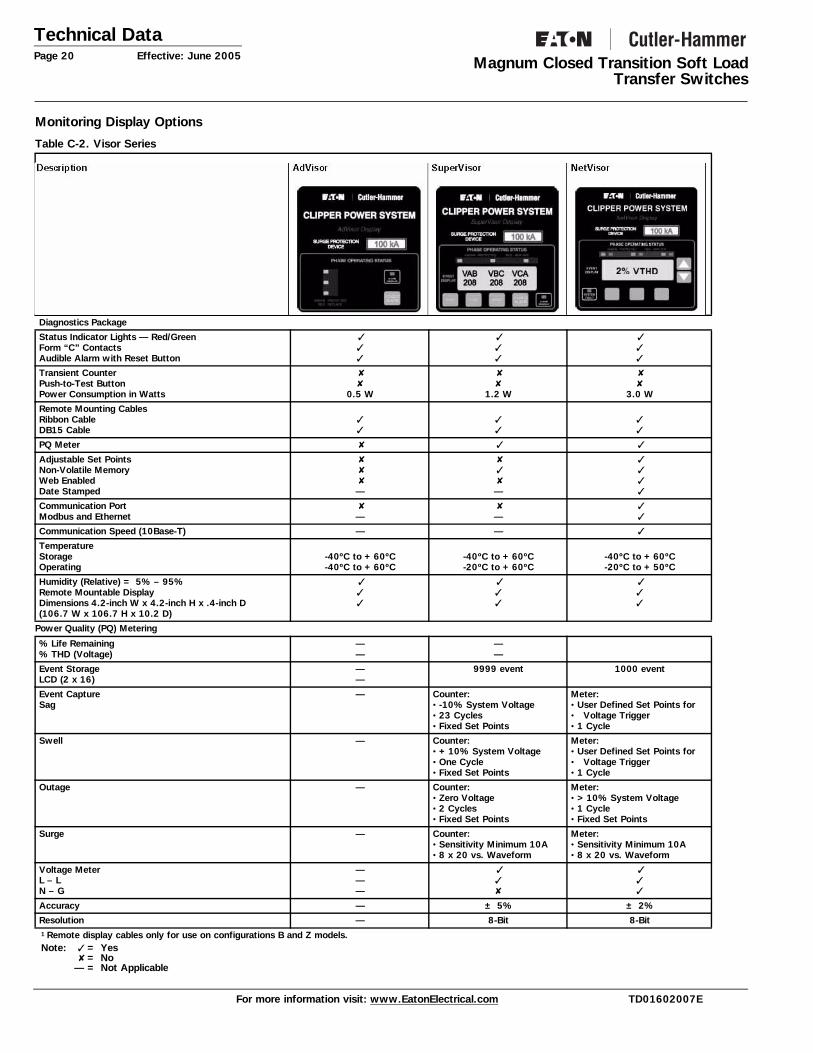
Monitoring Display Options
Table C-2. Visor Series
Power Quality (PQ) Metering
1 Remote display cables only for use on configurations B and Z models. Note: = Yes
= No — = Not Applicable
Diagnostics Package
Status Indicator Lights — Red/Green Form “C” Contacts Audible Alarm with Reset Button
Transient Counter Push-to-Test Button Power Consumption in Watts
0.5 W
1.2 W
3.0 W
Remote Mounting Cables Ribbon Cable DB15 Cable
PQ Meter
Adjustable Set Points Non-Volatile Memory Web Enabled Date Stamped
—
—
Communication Port Modbus and Ethernet
—
—
Communication Speed (10Base-T) — —
Temperature Storage Operating
-40ºC to +60ºC -40ºC to +60ºC
-40ºC to +60ºC -20ºC to +60ºC
-40ºC to +60ºC -20ºC to +50ºC
Humidity (Relative) = 5% – 95% Remote Mountable Display Dimensions 4.2-inch W x 4.2-inch H x .4-inch D (106.7 W x 106.7 H x 10.2 D)
% Life Remaining % THD (Voltage)
— —
— —
Event Storage LCD (2 x 16)
— —
9999 event
1000 event
Event Capture Sag
— Counter: • -10% System Voltage • 23 Cycles • Fixed Set Points
Meter: • User Defined Set Points for • Voltage Trigger • 1 Cycle
Swell — Counter: • +10% System Voltage • One Cycle • Fixed Set Points
Meter: • User Defined Set Points for• Voltage Trigger • 1 Cycle
Outage — Counter: • Zero Voltage • 2 Cycles • Fixed Set Points
Meter: • >10% System Voltage • 1 Cycle • Fixed Set Points
Surge — Counter: • Sensitivity Minimum 10A • 8 x 20 vs. Waveform
Meter: • Sensitivity Minimum 10A • 8 x 20 vs. Waveform
Voltage Meter L – L N – G
— — —
Accuracy — ± 5% ± 2%
Resolution — 8-Bit 8-Bit
For more information visit: www.EatonElectrical.com TD01602007E

Technical DataEffective: June 2005 Page 21
Magnum Closed Transition Soft LoadTransfer Switches
Notes
TD01602007E For more information visit: www.EatonElectrical.com

Technical DataPage 22 Effective: June 2005 Magnum Closed Transition Soft Load
Transfer Switches
Notes
For more information visit: www.EatonElectrical.com TD01602007E
Technical DataEffective: June 2005 Page 23
Magnum Closed Transition Soft LoadTransfer Switches
Notes
TD01602007E For more information visit: www.EatonElectrical.com
Technical DataPage 24 Effective: June 2005
Magnum Closed Transition Soft LoadTransfer Switches
© 2005 Eaton CorporationAll Rights Reserved
Eaton Electrical Inc.1000 Cherrington ParkwayMoon Township, PA 15108-4312USAtel: 1-800-525-2000www.EatonElectrical.com
Printed in USAPublication No. TD01602007E / TBG00094June 2005