Embed Size (px)
Citation preview
HASP Payload Specification and Integration Plan
Doc Version 091107 1 of 15
Payload Title: Student Payload Integrated First Flight (SPIFF)
Payload Class: Small Large (circle one)
Payload ID: 2012-01
Institution: Boston University / GA Tech / New Mexico Tech
Contact Name: Nathan Darling
Contact Phone: 617 353 0285
Contact E-mail: [email protected]
Submit Date: June 22, 2012
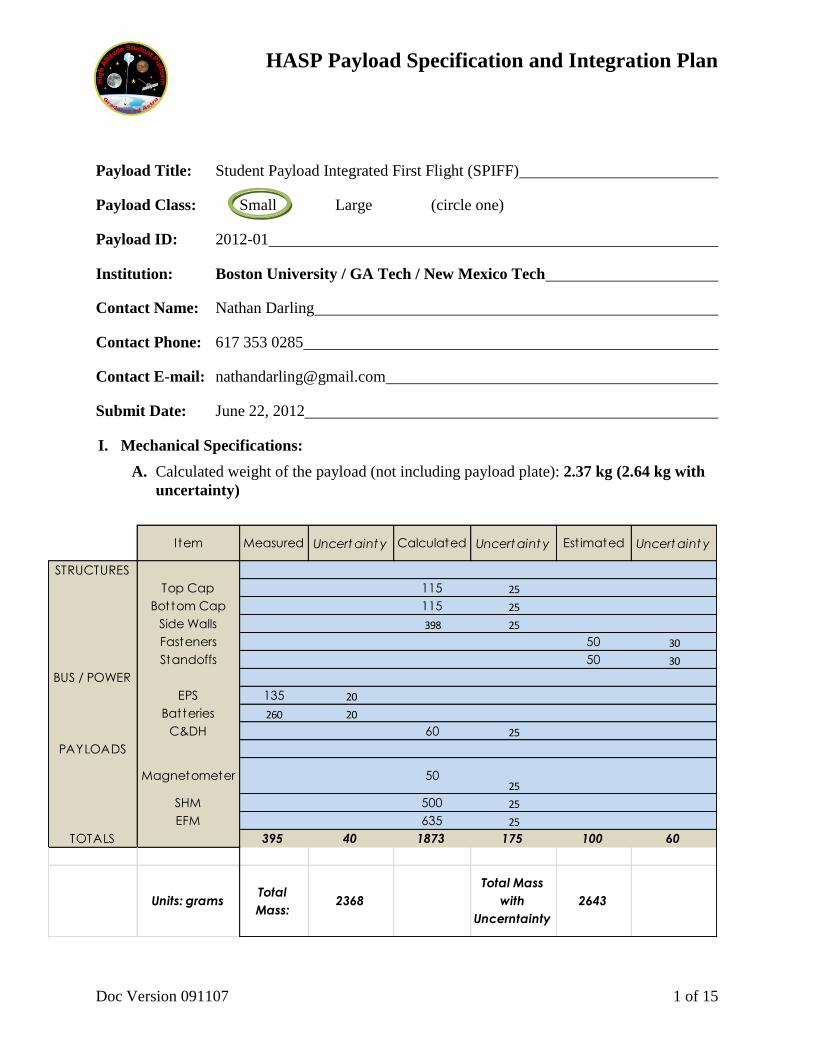
I. Mechanical Specifications:
A. Calculated weight of the payload (not including payload plate): 2.37 kg (2.64 kg with
uncertainty)
I tem Measured Uncertaint y Calculated Uncertaint y Est imated Uncertaint y
STRUCTURES
Top Cap 115 25
Bottom Cap 115 25
Side Walls 398 25
Fasteners 50 30
Standoffs 50 30
BUS / POWER
EPS 135 20
Batteries 260 20
C&DH 60 25
PAYLOADS
Magnetometer 5025
SHM 500 25
EFM 635 25
TOTALS 395 40 1873 175 100 60
Units: gramsTotal
Mass:2368
Total Mass
with
Uncerntainty
2643
HASP Payload Specification and Integration Plan
Doc Version 091107 2 of 15
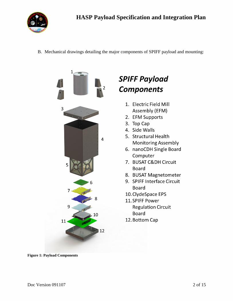
B. Mechanical drawings detailing the major components of SPIFF payload and mounting:
Figure 1: Payload Components
HASP Payload Specification and Integration Plan
Doc Version 091107 3 of 15
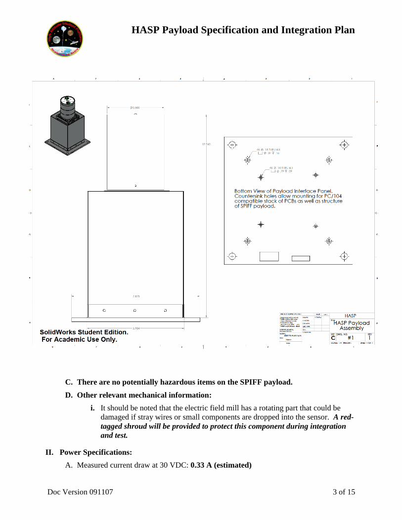
C. There are no potentially hazardous items on the SPIFF payload.
D. Other relevant mechanical information:
i. It should be noted that the electric field mill has a rotating part that could be
damaged if stray wires or small components are dropped into the sensor. A red-
tagged shroud will be provided to protect this component during integration
and test.
II. Power Specifications:
A. Measured current draw at 30 VDC: 0.33 A (estimated)
HASP Payload Specification and Integration Plan
Doc Version 091107 4 of 15
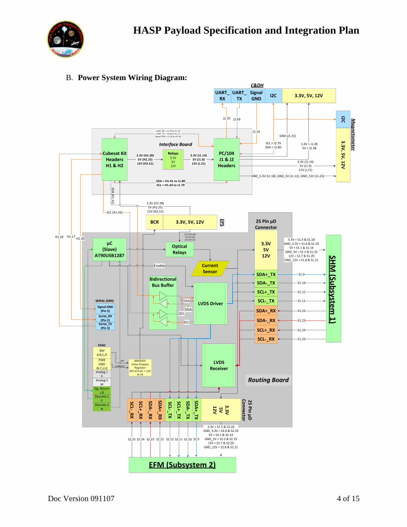
B. Power System Wiring Diagram:
3.3V5V
12V
µC(Slave)
AT90USB1287
Bidirectional Bus Buffer
LVDS Driver
LVDS Receiver
SDA
SCLSDA
SCL
Optical Relays
Current Sensor
SDA+_TX
SDA-_TX
SCL+_TX
SCL-_TX
SDA+_RX
SDA-_RX
SCL+_RX
SCL-_RX
Enable
25 Pin µD Connector
SHM
(Sub
system
1)
Routing Board
3.3V = S1.5 & S1.18GND_3.3V = S1.6 & S1.19
5V = S1.1 & S1.14GND_5V = S1.2 & S1.15
12V = S1.7 & S1.20GND_12V = S1.8 & S1.21
S1.9
S1.10
S1.22
S1.11
S1.12
S1.23
S1.24
S1.25
3.3
V5
V1
2V
SDA
+_TX
SDA
-_TX
SCL+_TX
SCL-_TX
SDA
+_RX
SDA
-_RX
SCL+_R
X
SCL-_R
X
3.3V = S2.5 & S2.18GND_3.3V = S2.6 & S2.19
5V = S2.1 & S2.14GND_5V = S2.2 & S2.15
12V = S2.7 & S2.20GND_12V = S2.8 & S2.21
S2.9S2.10S2.22 S2.11S2.12S2.23S2.24S2.25
EFM (Subsystem 2)
30VA,B,C,D
PWRGND
W,T,U,XAnalog 1
KAnalog 2
MSig. Return
L,RDiscrete 1
FDiscrete 2
N
MAX5035Linear Dropout
Regulator30V at 0.5A -> 12V
at 1A
25
Pin
µD
C
on
ne
ctor
3.3V, 5V, 12V
EPS
3.3V, 5V, 12VUART_
TXUART_
RX
3.3
V, 5
V, 1
2V
I2C M
ag
neto
meter
C&DH
30V
HASP GND
BCR
Cubesat Kit HeadersH1 & H2
Relays3.3V5V
12V
3.3V (H2.28)5V (H2.25)
12V (H2.51)
PC/104J1 & J2
Headers
Serial_TX(Pin 3)
Serial_RX(Pin 2)
Signal GND(Pin 5)
3.3V (J1.14)5V (J1.9)
12V (J.21)
SDA = H1.41 to J1.80SCL = H1.43 to J1.79
Interface Board
SCL (H1.43)
3.3V (H2.28)5V (H2.25)
12V (H2.51)
3.3V (H2.28)5V (H2.25)
12V (H2.51)
Signal GND
3.3V (J1.14)5V (J1.9)
12V (J.21)
J1.24
J2.69J2.70
UART_RX = J2.70 to H1.18UART_TX = J2.69 to H1.17
Signal GND = J2.24 to H2.30
H2.30H1.17H1.18
I2C
SCL = J2.79SDA = J2.80
EDAC
SERIAL (DB9)
GND_3.3V (J1.18), GND_5V (J1.12), GND_12V (J1.23)
GND (J1.31)
SDA
(H1
.41
)
3.3V = J1.395V = J1.38
HASP Payload Specification and Integration Plan
Doc Version 091107 5 of 15
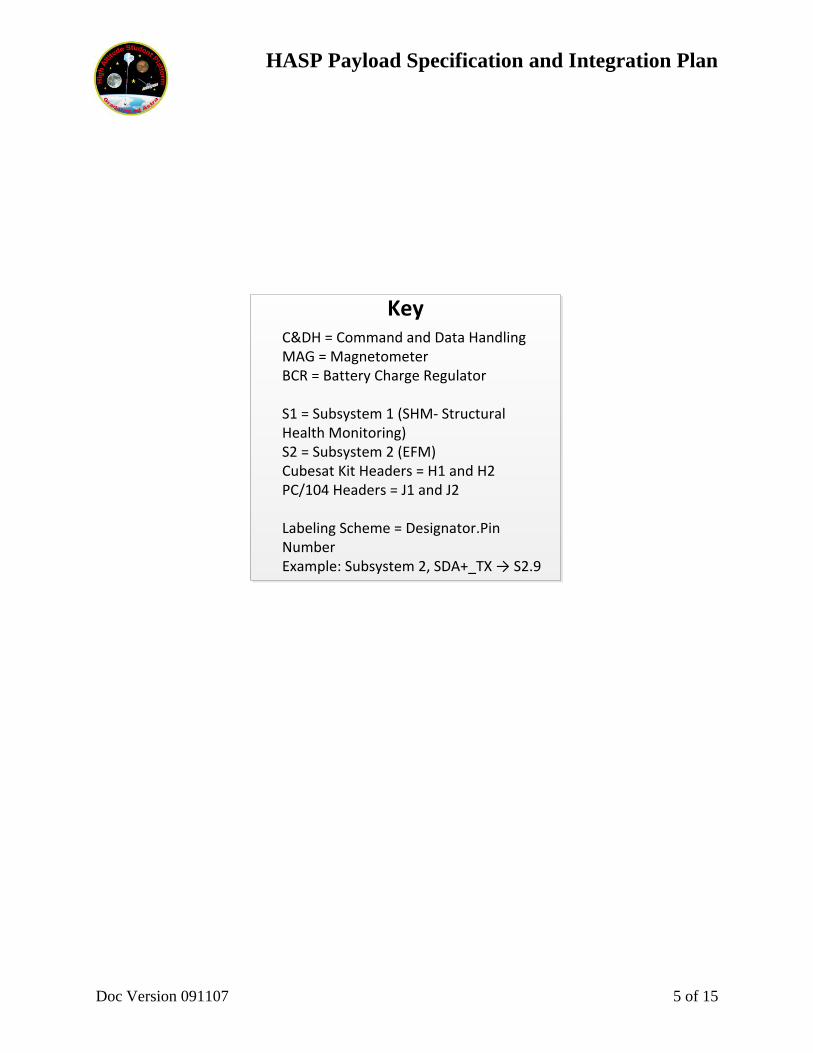
KeyC&DH = Command and Data HandlingMAG = MagnetometerBCR = Battery Charge Regulator
S1 = Subsystem 1 (SHM- Structural Health Monitoring)S2 = Subsystem 2 (EFM)Cubesat Kit Headers = H1 and H2PC/104 Headers = J1 and J2
Labeling Scheme = Designator.Pin NumberExample: Subsystem 2, SDA+_TX → S2.9
HASP Payload Specification and Integration Plan
Doc Version 091107 6 of 15
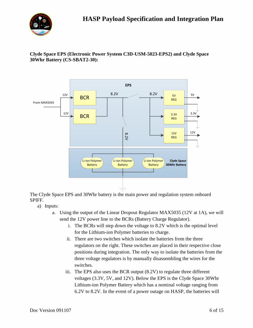
Clyde Space EPS (Electronic Power System C3D-USM-5023-EPS2) and Clyde Space
30Whr Battery (CS-SBAT2-30):
EPS
BCR
BCR
5V REG
3.3V REG
12V REG
8.2V12V
12V
8.2V
Clyde Space30Whr Battery
Li-ion Polymer Battery
Li-ion Polymer Battery
Li-ion Polymer Battery
8.2
V
5V
3.3V
12V
From MAX5035
The Clyde Space EPS and 30Whr battery is the main power and regulation system onboard
SPIFF.
a) Inputs:
a. Using the output of the Linear Dropout Regulator MAX5035 (12V at 1A), we will
send the 12V power line to the BCRs (Battery Charge Regulator).
i. The BCRs will step down the voltage to 8.2V which is the optimal level
for the Lithium-ion Polymer batteries to charge.
ii. There are two switches which isolate the batteries from the three
regulators on the right. These switches are placed in their respective close
positions during integration. The only way to isolate the batteries from the
three voltage regulators is by manually disassembling the wires for the
switches.
iii. The EPS also uses the BCR output (8.2V) to regulate three different
voltages (3.3V, 5V, and 12V). Below the EPS is the Clyde Space 30Whr
Lithium-ion Polymer Battery which has a nominal voltage ranging from
6.2V to 8.2V. In the event of a power outage on HASP, the batteries will
HASP Payload Specification and Integration Plan
Doc Version 091107 7 of 15
become the source of power for SPIFF. It is important to note that all the
grounds will converge to the battery ground and then ultimately to the
HASP power ground.
b) Outputs:
a. The EPS and battery will output 3.3V, 5V, and 12V with a common ground
between the three voltages.
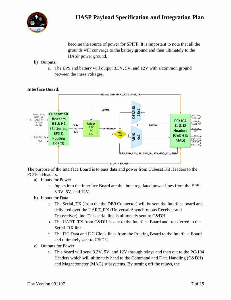
Interface Board:
Cubesat Kit HeadersH1 & H2
(Batteries, EPS &
Routing Board)
DEM
UX
16
x1M
UX
4x1
ANDGate
Relays3.3V5V
12V
Control
SIGNAL GND, UART_RX & UART_TX
I2C DATA & Clock
3.3V5V
12VVerification
Control
PC/104J1 & J2
Headers(C&DH &
MAG)
3.3V,GND_3.3V, 5V, GND_5V, 12V, GND_12V, GND
3.3V, 5V, 12V
UART_RXUART_TX
3.3V, 5V,12V
SIGNAL GND, UART_RX, UART_TXI2C DATAI2C CLK
GND_3.3VGND_5V
GND_12V
GND
GND
I2C DataI2C Clock
The purpose of the Interface Board is to pass data and power from Cubesat Kit Headers to the
PC/104 Headers.
a) Inputs for Power
a. Inputs into the Interface Board are the three regulated power lines from the EPS:
3.3V, 5V, and 12V.
b) Inputs for Data
a. The Serial_TX (from the the DB9 Connector) will be sent the Interface board and
delivered over the UART_RX (Universal Asynchronous Receiver and
Transceiver) line. This serial line is ultimately sent to C&DH.
b. The UART_TX from C&DH is sent to the Interface Board and transferred to the
Serial_RX line.
c. The I2C Data and I2C Clock lines from the Routing Board to the Interface Board
and ultimately sent to C&DH.
c) Outputs for Power
a. This board will send 3.3V, 5V, and 12V through relays and then out to the PC/104
Headers which will ultimately head to the Command and Data Handling (C&DH)
and Magnetometer (MAG) subsystems. By turning off the relays, the
HASP Payload Specification and Integration Plan
Doc Version 091107 8 of 15
Magnetometer subsystem will shut off, but C&DH will remain powered. These
relays are controlled by C&DH via their microcontroller.
b. Isolated grounds will be sent to the Magnetometer subsystems: GND_3.3V,
GND_5V and GND_12V.
c. The EPS ground is sent to the C&DH Subsystem.
d) Outputs for Data
a. The Cubesat Kit Headers will pass the serial UART_TX to the Serial_RX on the
DB9 connector (located on the Routing Board).
b. The I2C lines will also be originating from C&DH to the Routing Board for
communication to the EFM, SHM, and the Routing Board.
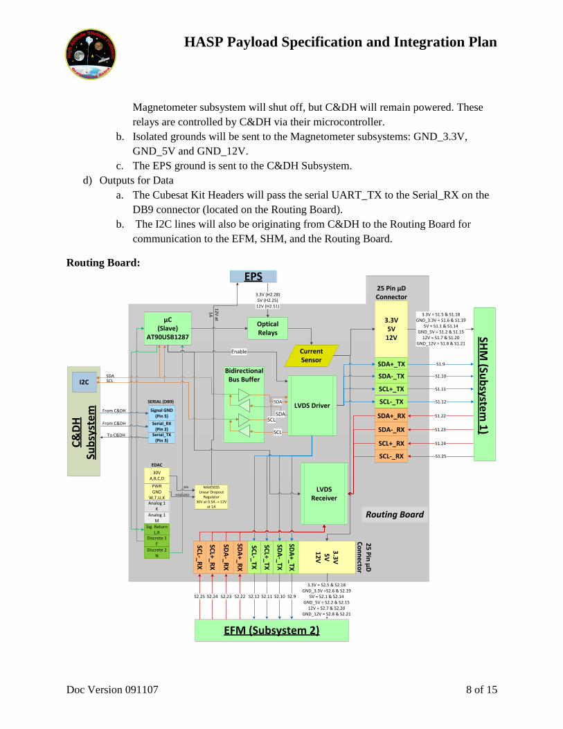
Routing Board:
3.3V5V
12V
µC(Slave)
AT90USB1287
Bidirectional Bus Buffer
LVDS Driver
LVDS Receiver
SDA
SCLSDA
SCL
Optical Relays
Current Sensor
SDA+_TX
SDA-_TX
SCL+_TX
SCL-_TX
SDA+_RX
SDA-_RX
SCL+_RX
SCL-_RX
Enable
25 Pin µD Connector
SHM
(Sub
system
1)
Routing Board
3.3V = S1.5 & S1.18GND_3.3V = S1.6 & S1.19
5V = S1.1 & S1.14GND_5V = S1.2 & S1.15
12V = S1.7 & S1.20GND_12V = S1.8 & S1.21
S1.9
S1.10
S1.22
S1.11
S1.12
S1.23
S1.24
S1.25
3.3
V5
V1
2V
SDA
+_TX
SDA
-_TX
SCL+_TX
SCL-_TX
SDA
+_RX
SDA
-_RX
SCL+_R
X
SCL-_R
X
3.3V = S2.5 & S2.18GND_3.3V =S2.6 & S2.19
5V = S2.1 & S2.14GND_5V = S2.2 & S2.15
12V = S2.7 & S2.20GND_12V = S2.8 & S2.21
S2.9S2.10S2.22 S2.11S2.12S2.23S2.24S2.25
EFM (Subsystem 2)
30VA,B,C,D
PWRGND
W,T,U,XAnalog 1
KAnalog 1
MSig. Return
L,RDiscrete 1
FDiscrete 2
N
MAX5035Linear Dropout
Regulator30V at 0.5A -> 12V
at 1A
25
Pin
µD
C
on
ne
ctor
30V
HASP GND
Serial_TX(Pin 3)
Serial_RX(Pin 2)
Signal GND(Pin 5)
EDAC
SERIAL (DB9)
SDASCLI2C
12
V at
1A
To C&DH
From C&DH
From C&DH
3.3V (H2.28)5V (H2.25)
12V (H2.51)
EPS
C&
DH
Su
bsy
ste
m
HASP Payload Specification and Integration Plan
Doc Version 091107 9 of 15
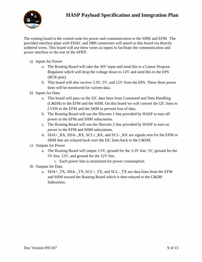
The routing board is the central node for power and communication to the SHM and EFM. The
provided interface plate with EDAC and DB9 connectors will attach to this board via directly
soldered wires. This board will use these wires as inputs to facilitate the communication and
power interface to the rest of the SPIFF.
a) Inputs for Power
a. The Routing Board will take the 30V input and send this to a Linear Dropout
Regulator which will drop the voltage down to 12V and send this to the EPS
(BCR pins).
b. This board will also receive 3.3V, 5V, and 12V from the EPS. These three power
lines will be monitored for current data.
b) Inputs for Data
a. This board will pass on the I2C data lines from Command and Data Handling
(C&DH) to the EFM and the SHM. On this board we will convert the I2C lines to
LVDS to the EFM and the SHM to prevent loss of data.
b. The Routing Board will use the Discrete 1 line provided by HASP to turn off
power to the EFM and SHM subsystems.
c. The Routing Board will use the Discrete 2 line provided by HASP to turn on
power to the EFM and SHM subsystems.
d. SDA+_RX, SDA-_RX, SCL+_RX, and SCL-_RX are signals sent for the EFM or
SHM that are relayed back over the I2C lines back to the C&DH.
c) Outputs for Power
a. The Routing Board will output 3.3V, ground for the 3.3V line, 5V, ground for the
5V line, 12V, and ground for the 12V line.
i. Each power line is monitored for power consumption.
d) Outputs for Data
a. SDA+_TX, SDA-_TX, SCL+_TX, and SCL-_TX are data lines from the EFM
and SHM toward the Routing Board which is then relayed to the C&DH
Subsystem.
HASP Payload Specification and Integration Plan
Doc Version 091107 10 of 15
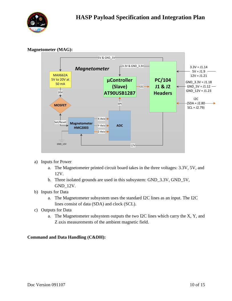
Magnetometer (MAG):
MAX662A5V to 20V at
50 mAPC/104J1 & J2
Headers
MOSFET
20V
MagnetometerHMC2003
Set/Reset
GND_12V
ADCY-Axis
Z-Axis
X-Axis
12V
µController(Slave)
AT90USB1287
SPI
I2C
5V & GND_5V
3.3V & GND_3.3V
I2C(SDA = J2.80SCL = J2.79)
3.3V = J1.145V = J1.9
12V = J1.21
GND_3.3V = J1.18GND_5V = J1.12
GND_12V = J1.23
Magnetometer
a) Inputs for Power
a. The Magnetometer printed circuit board takes in the three voltages: 3.3V, 5V, and
12V.
b. Three isolated grounds are used in this subsystem: GND_3.3V, GND_5V,
GND_12V.
b) Inputs for Data
a. The Magnetometer subsystem uses the standard I2C lines as an input. The I2C
lines consist of data (SDA) and clock (SCL).
c) Outputs for Data
a. The Magnetometer subsystem outputs the two I2C lines which carry the X, Y, and
Z axis measurements of the ambient magnetic field.
Command and Data Handling (C&DH):
HASP Payload Specification and Integration Plan
Doc Version 091107 11 of 15
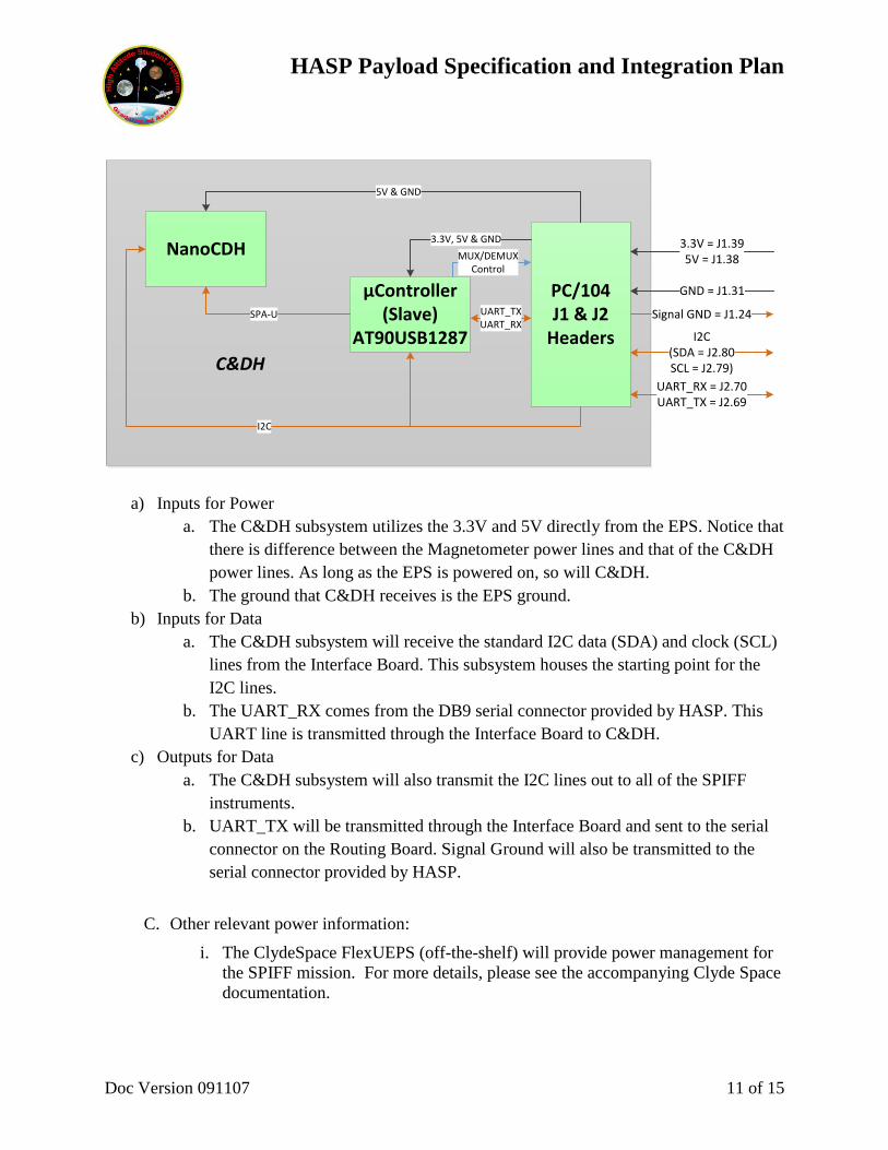
PC/104J1 & J2
Headers
µController(Slave)
AT90USB1287
3.3V, 5V & GNDNanoCDH
5V & GND
SPA-U
I2C
UART_TXUART_RX
MUX/DEMUXControl
I2C(SDA = J2.80SCL = J2.79)
3.3V = J1.395V = J1.38
GND = J1.31
UART_RX = J2.70UART_TX = J2.69
C&DH
Signal GND = J1.24
a) Inputs for Power
a. The C&DH subsystem utilizes the 3.3V and 5V directly from the EPS. Notice that
there is difference between the Magnetometer power lines and that of the C&DH
power lines. As long as the EPS is powered on, so will C&DH.
b. The ground that C&DH receives is the EPS ground.
b) Inputs for Data
a. The C&DH subsystem will receive the standard I2C data (SDA) and clock (SCL)
lines from the Interface Board. This subsystem houses the starting point for the
I2C lines.
b. The UART_RX comes from the DB9 serial connector provided by HASP. This
UART line is transmitted through the Interface Board to C&DH.
c) Outputs for Data
a. The C&DH subsystem will also transmit the I2C lines out to all of the SPIFF
instruments.
b. UART_TX will be transmitted through the Interface Board and sent to the serial
connector on the Routing Board. Signal Ground will also be transmitted to the
serial connector provided by HASP.
C. Other relevant power information:
i. The ClydeSpace FlexUEPS (off-the-shelf) will provide power management for
the SPIFF mission. For more details, please see the accompanying Clyde Space
documentation.
HASP Payload Specification and Integration Plan
Doc Version 091107 12 of 15
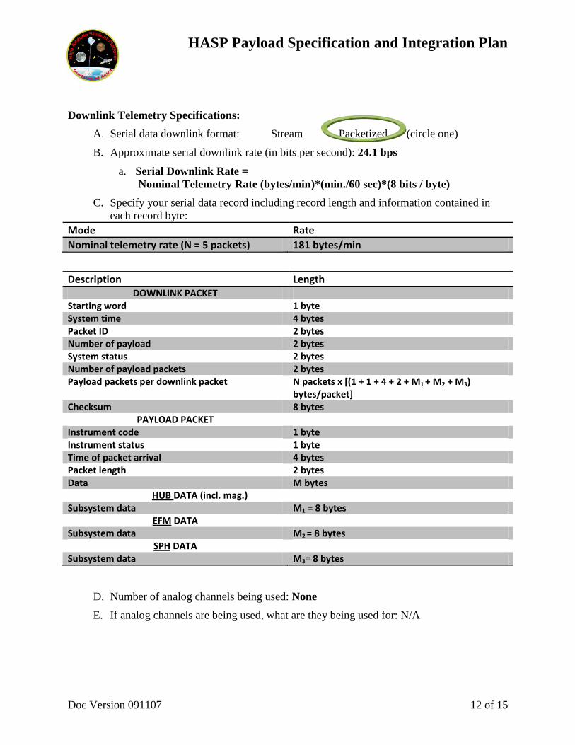
Downlink Telemetry Specifications:
A. Serial data downlink format: Stream Packetized (circle one)
B. Approximate serial downlink rate (in bits per second): 24.1 bps
a. Serial Downlink Rate =
Nominal Telemetry Rate (bytes/min)*(min./60 sec)*(8 bits / byte)
C. Specify your serial data record including record length and information contained in
each record byte:
Mode Rate
Nominal telemetry rate (N = 5 packets) 181 bytes/min
Description Length DOWNLINK PACKET
Starting word 1 byte System time 4 bytes Packet ID 2 bytes Number of payload 2 bytes System status 2 bytes Number of payload packets 2 bytes Payload packets per downlink packet N packets x [(1 + 1 + 4 + 2 + M1 + M2 + M3)
bytes/packet] Checksum 8 bytes
PAYLOAD PACKET Instrument code 1 byte Instrument status 1 byte Time of packet arrival 4 bytes Packet length 2 bytes Data M bytes
HUB DATA (incl. mag.) Subsystem data M1 = 8 bytes
EFM DATA Subsystem data M2 = 8 bytes
SPH DATA Subsystem data M3= 8 bytes
D. Number of analog channels being used: None
E. If analog channels are being used, what are they being used for: N/A
HASP Payload Specification and Integration Plan
Doc Version 091107 13 of 15
F. Number of discrete lines being used: None
G. If discrete lines are being used what are they being used for: N/A
H. Are there any on-board transmitters? If so, list the frequencies being used and the
transmitted power: N/A
I. Other relevant downlink telemetry information: N/A
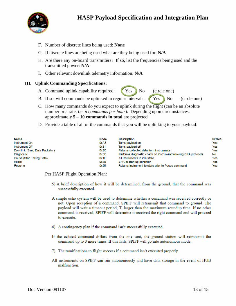
III. Uplink Commanding Specifications:
A. Command uplink capability required: Yes No (circle one)
B. If so, will commands be uplinked in regular intervals: Yes No (circle one)
C. How many commands do you expect to uplink during the flight (can be an absolute
number or a rate, i.e. n commands per hour): Depending upon circumstances,
approximately 5 – 10 commands in total are projected.
D. Provide a table of all of the commands that you will be uplinking to your payload:
Per HASP Flight Operation Plan:
HASP Payload Specification and Integration Plan
Doc Version 091107 14 of 15
E. Are there any on-board receivers? No. If so, list the frequencies being used: N/A
F. Other relevant uplink commanding information: N/A
IV. Integration and Logistics
A. Date and Time of your arrival for integration: July 30, 2012. Time pending flight
purchase.
B. Approximate amount of time required for integration: 3 hours
C. Name of the integration team leader: Christopher Hoffman
D. Email address of the integration team leader: [email protected]
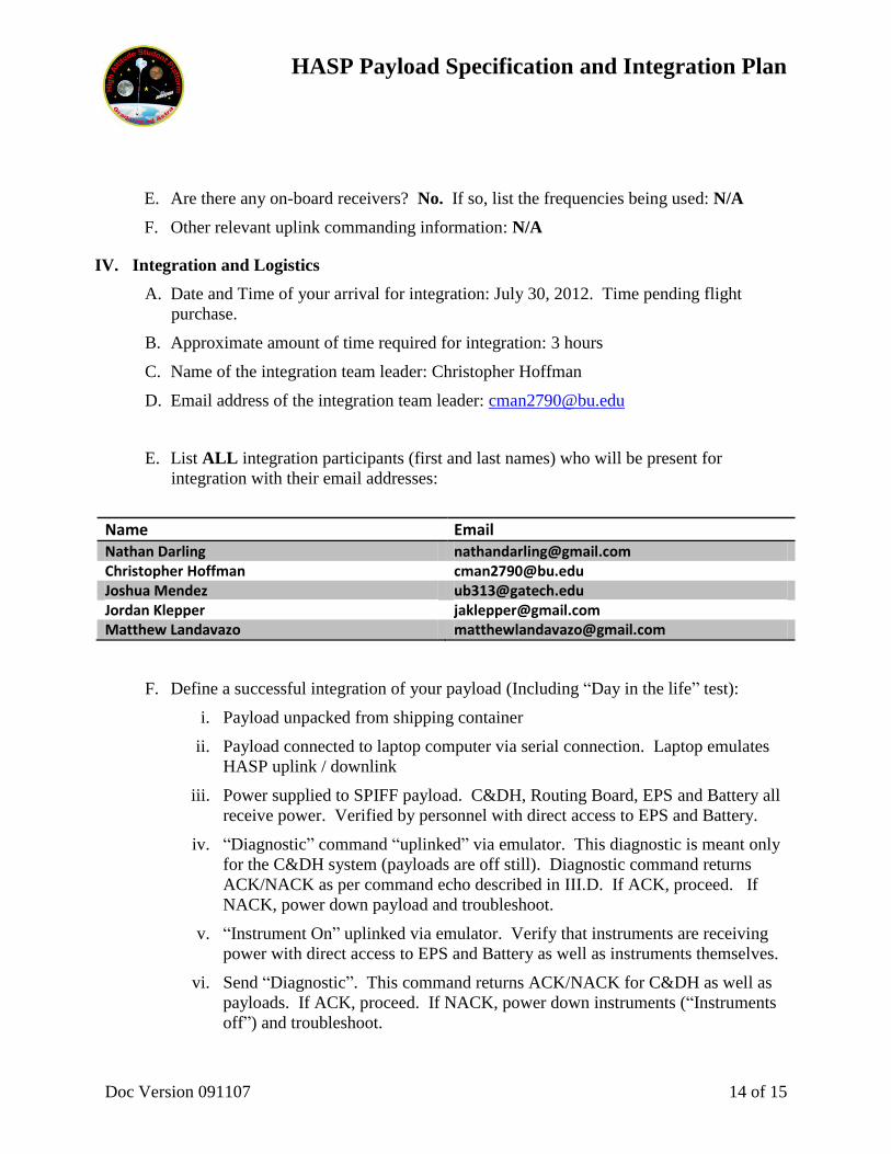
E. List ALL integration participants (first and last names) who will be present for
integration with their email addresses:
Name Email Nathan Darling [email protected] Christopher Hoffman [email protected] Joshua Mendez [email protected] Jordan Klepper [email protected] Matthew Landavazo [email protected]
F. Define a successful integration of your payload (Including “Day in the life” test):
i. Payload unpacked from shipping container
ii. Payload connected to laptop computer via serial connection. Laptop emulates
HASP uplink / downlink
iii. Power supplied to SPIFF payload. C&DH, Routing Board, EPS and Battery all
receive power. Verified by personnel with direct access to EPS and Battery.
iv. “Diagnostic” command “uplinked” via emulator. This diagnostic is meant only
for the C&DH system (payloads are off still). Diagnostic command returns
ACK/NACK as per command echo described in III.D. If ACK, proceed. If
NACK, power down payload and troubleshoot.
v. “Instrument On” uplinked via emulator. Verify that instruments are receiving
power with direct access to EPS and Battery as well as instruments themselves.
vi. Send “Diagnostic”. This command returns ACK/NACK for C&DH as well as
payloads. If ACK, proceed. If NACK, power down instruments (“Instruments
off”) and troubleshoot.
HASP Payload Specification and Integration Plan
Doc Version 091107 15 of 15
vii. Send “Downlink” command. Verify data downlinked.
viii. Send “Pause” command. Verify pause.
ix. Send “Resume” command. Verify data downlinkd.
x. Send “Pause” command. Verify Pause.
xi. Send “Reset” command, followed by “Diagnostic”.
This test sequence is meant to be repeated after mechanical interface to gondola is completed
(V.G.i) as “Day in the life” tests.
G. List all expected integration steps:
i. Thermal testing will be performed at Boston University prior to integration.
ii. Mechanical interface (structural and electrical) via mounting plate completed
iii. “Day in the life” test
iv. De-bug and re-run if necessary
H. List all checks that will determine a successful integration:
i. Data from “day in the life” test within expected parameters.
ii. Analog downlink data within expected parameters.
I. List any additional LSU personnel support needed for a successful integration other
than directly related to the HASP integration (i.e. lifting, moving equipment, hotel
information/arrangements, any special delivery needs…):
i. Hotel, rental car, public transportation and meals information would be greatly
appreciated
ii. No lifting or delivery needs.
J. List any LSU supplied equipment that may be needed for a successful integration:
i. Soldering Station (soldering iron, ESD protection, soldering supplies for simple
repairs of circuitry and wire harness.
ii. Multimeter
iii. Oscilloscope
iv. Power Supply


![Hillside Agriculture Sub-Project [HASP]](https://img.dokumen.tips/doc/110x75/627b6d82bef92b7d1806c9de/hillside-agriculture-sub-project-hasp.jpg)