Embed Size (px)
Citation preview

APPENDIX A
HEALTH AND SAFETY PLAN (HASP)
The final Health and Safety Plan will be maintained at the Study Area during field activities.

HEALTH AND SAFETY PLAN (HASP)
Office: West Chester, PA Project Name: Study Area Bounded by Pyrex Street, E. Pulteney Street,
Post Creek and Chemung River Client: Corning Incorporated Work Location: Corning, NY WO#: 02005.056.001.0001
HEALTH AND SAFETY PLAN (HASP)
Work Order Number Date Project Manager ApprovalProject Safety Manager
Approval

HEALTH AND SAFETY PLAN (HASP)
Prepared by: A. Jayne / R. McLoughlin W.O. Number: 02005.056.001.0001 Date: 03/28/2014
Project Identification
Study Area Bounded by Pyrex St., E. Pulteney St., Post Creek and Chemung River
History: Soil and/or groundwater characterization activities at a site with potential fill containing ash, brick and glass pieces.
Office: West Chester, PA Site Name: Study Area, Corning, New York Client: Corning Incorporated Work Location Address:
Located in Corning, New York on the north bank of the Chemung River (see Figure 1).
Scope of Work: Study Area Characterization Activities Site visit only; site HASP not necessary. List personnel here and sign off below:
X Utility notification required. If required, provide utility notification agency, authorization number, and valid dates:
Regulatory Status: Site regulatory status: TBD CERCLA/SARA RCRA Other Federal Agency
U.S. EPA U.S. EPA DOE
State State USACE
NPL Site NRC Air Force
OSHA 10 CFR 20
Hazard Communication (Req'd See Attachment D) 1910 1926 State
Safety Officer Manual (Required to be On-Site) Based on the Hazard Assessment and Regulatory Status, determine the Standard
HASP(s) applicable to this project. Indicate below which Standard HASP will be
used and append the appropriate pages of this form along with the Standard Plan.
Stack Test
Air Emissions
Asbestos
Industrial Hygiene
Review and Approval Documentation: Reviewed by: SO/DEHSM/CEHS George Crawford Date:
Name (Print) Signature Environmental. Compliance Advisor Date:
Name (Print) Signature Approved by: Project Manager John Sontag Date:
Name (Print) Signature
Hazard Assessment and Equipment Selection: In accordance with WESTON’s Personal Protective Equipment Program and 29 CFR 1910.132, at the site prior to personnel beginning work, the FSO and/or the Site Manager have evaluated conditions and verified that the personal protective equipment selection outlined within this HASP is appropriate for the hazards known or expected to exist. (Refer to CEHS Program Manual Section 5, Personal Protection Program, for guidance.)
FSO Dave Cairns Date:
Name Signature
Site Manager John Sontag Date: Name Signature
Project Environmental Compliance Officer John Sontag Date:
Name Dangerous Goods Shipping
Coordinator Rachel McLoughlin Date:
Name

BEHAVIOR-BASED SAFETY (BBS) – Pledge
I Accept and Understand 100% Safe Work Is an Achievable Goal I will work to develop strong connections and team with my co-workers to establish a
culture of working safely 100% of the time.
I will actively care about all Weston employees, our families, team contractors and clients.
I will help to keep our projects safe and will meet and exceed compliance requirements.
I will understand and comply with the Health and Safety Plan, Accident Prevention Plan, and Environmental Compliance Plan for each field project. They guide my actions.
I will stop any work that presents an imminent hazard to people or the environment or is not adequately addressed in the Health and Safety Plan, Accident Prevention Plan, or Environmental Compliance Plan.
I will identify changing conditions to address safety implications. No surprises!
I will identify unsafe working conditions and be proactive in correcting them.
I will coach and mentor and will accept coaching from others to encourage safe work behaviors.
I am empowered to share lessons-learned and foster continuous improvement.
I will Learn where I can get Assistance I will develop high quality relationships with my Division Environmental, Health, and Safety
(EHS) Manager; Profit Center Safety Officer; and Field Safety Officer.
I will learn how and when to contact our Environmental Advisors.
I will get to know our Corporate EHS staff and become familiar with the Corporate EHS Portal Site.
I will Report All Incidents If a safety incident occurs, even if there is no injury or damage but there could have been,
I will report the incident immediately.
I will conduct safety reviews of all incidents with my supervisor, if requested. The review will focus on cause and lessons-learned so that we can be proactive in preventing it from happening again.

June 2014
The information contained in this document is the property of Weston Solutions, Inc. and may not be used or reproduced in any form without the written permission of Weston Solutions, Inc.
TABLE OF CONTENTS Section Page
1. PERSONNEL ON SITE INFORMATION 1-1 1.1 WESTON REPRESENTATIVES .................................................................. 1-2 1.2 WESTON SUBCONTRACTORS ................................................................. 1-2 1.3 SITE PERSONNEL AND CERTIFICATION STATUS .................................. 1-3
1.3.1 WESTON Employee Certification ....................................................... 1-3 1.3.2 Subcontractor's Health and Safety Program Evaluation ..................... 1-4
2. HEALTH AND SAFETY EVALUATION 2-1 2.1 HEALTH AND SAFETY EVALUATION ........................................................ 2-2
2.1.1 Task Hazard Assessment ................................................................... 2-2 2.1.2 Chemical Hazards of Concern ............................................................ 2-3 2.1.3 Biological Hazards of Concern ............................................................ 2-4 2.1.4 Radiation Hazards of Concern ............................................................ 2-5 2.1.5 Physical Hazards of Concern .............................................................. 2-6
3. SITE SECURITY 3-1 3.1 SITE SECURITY ASSESSMENT FORM ..................................................... 3-2 3.2 WESTON SITE SECURITY CHECKLIST ..................................................... 3-3
4. TASK BY TASK ASSESSMENT 4-1 4.1 TASK-BY-TASK RISK ASSESSMENT ........................................................ 4-2
4.1.1 Task 1 Description .............................................................................. 4-2 4.1.2 Task 2 Description .............................................................................. 4-3 4.1.3 Task 3 Description .............................................................................. 4-4
4.2 PERSONNEL PROTECTION PLAN ............................................................ 4-5 4.3 DESCRIPTION OF LEVELS OF PROTECTION .......................................... 4-6
5. MONITORING PROGRAM 5-1 5.1.1 Air Monitoring Instruments .................................................................. 5-2 5.1.1 Air Monitoring Instruments Calibration Record ................................... 5-3
5.2 SITE AIR MONITORING PROGRAM .......................................................... 5-4 5.3 ACTION LEVELS ......................................................................................... 5-5
6. HOSPITAL INFORMATION 6-1 6.1 CONTINGENCIES ....................................................................................... 6-2
6.1.1 Emergency Contacts and Phone Numbers ......................................... 6-2 6.1.2 Hospital Map ....................................................................................... 6-4 6.1.3 Response Plans .................................................................................. 6-5
7. DECONTAMINATION PLAN 7-1 7.1 GENERAL DECONTAMINATION PLAN ...................................................... 7-2 7.2 LEVEL D DECONTAMINATION PLAN ........................................................ 7-3 7.3 LEVEL C DECONTAMINATION PLAN ........................................................ 7-4 7.4 LEVEL B ( ) or Level A ( ) DECONTAMINATION PLAN ........................... 7-5
8. TRAINING AND BRIEFING TOPICS/SIGN OFF SHEET 8-1 8.1 TRAINING AND BRIEFING TOPICS ........................................................... 8-2 8.2 HEALTH AND SAFETY PLAN APPROVAL/SIGNOFF FORM ..................... 8-3

June 2014
The information contained in this document is the property of Weston Solutions, Inc. and may not be used or reproduced in any form without the written permission of Weston Solutions, Inc.
ATTACHMENTS
ATTACHMENT A Chemical Contaminants Data Sheets
ATTACHMENT B Safety Data Sheets
ATTACHMENT C Safety Procedures/Field Operating Procedures (FLD Ops)
ATTACHMENT D Hazard Communication Program
ATTACHMENT E Air Sampling Data Sheets
ATTACHMENT F Incident Reporting
ATTACHMENT G Traffic Control Plan
ATTACHMENT H Environmental Health & Safety Inspection Checklist

June 2014
The information contained in this document is the property of Weston Solutions, Inc. and may not be used or reproduced in any form without the written permission of Weston Solutions, Inc.
1-1
1. PERSONNEL ON SITE INFORMATION

June 2014
The information contained in this document is the property of Weston Solutions, Inc. and may not be used or reproduced in any form without the written permission of Weston Solutions, Inc.
1-2
1.1 WESTON REPRESENTATIVES Organization/Branch Name/Title Address Telephone
National Accounts John Sontag/Project Manager
1400 Weston Way West Chester, PA 19380
610-701-3679
National Accounts Rachel McLoughlin/Project Scientist
1400 Weston Way West Chester, PA 19380
610-701-3428
National Accounts Dave Cairns/ Senior Geoscientist
1400 Weston Way West Chester, PA 19380
610-701-3676
Roles and Responsibilities:
Manage and implement site characterization program.
1.2 WESTON SUBCONTRACTORS Organization/Branch Name/Title Address Telephone
Name: Title:
Street: City: State, Zip:
Name: Title:
Street: City: State, Zip:
Name: Title:
Street: City: State, Zip:
Roles and Responsibilities:
SITE-SPECIFIC HEALTH AND SAFETY PERSONNEL The Site Field Safety Officer (FSO) for activities to be conducted at this site is: Dave Cairns
The Site Manager has ultimate responsibility for ensuring that the provisions of this Site HASP are adequate and implemented in the field.
Changing field conditions may require decisions to be made concerning adequate protection programs. Therefore, the personnel assigned as FSOs must be experienced and meet the additional training requirements specified by OSHA in 29 CFR 1910.120.
Qualifications: 40-hour OSHA HAZWOPER certification; annual 8-hour OSHA HAZWOPER refresher certification; current Adult First Aid and CPR certification; familiarity with jobs of similar scope.
Designated alternates include: John Sontag, Rachel McLoughlin

June 2014
The information contained in this document is the property of Weston Solutions, Inc. and may not be used or reproduced in any form without the written permission of Weston Solutions, Inc.
1-3
1.3 SITE PERSONNEL AND CERTIFICATION STATUS 1.3.1 WESTON Employee Certification
Name: John Sontag Title: Project Manager Task(s): All Certification Level or Description:
Name: Dave Cairns Title: Senior Geoscientist Task(s): All Certification Level or Description:
Medical Current Fit Test Current (Qual.)
Training Current Fit Test Current (Quant.)
Medical Current Fit Test Current (Qual.)
Training Current Fit Test Current (Quant.)
Name: Rachel McLoughlin Title: Project Scientist Task(s): All Certification Level or Description:
Name: Title: Task(s): Certification Level or Description:
Medical Current Fit Test Current (Qual.)
Training Current Fit Test Current (Quant.)
Medical Current Fit Test Current (Qual.)
Training Current Fit Test Current (Quant.)
Name: Title: Task(s): Certification Level or Description:
Name: Title: Task(s): Certification Level or Description:
Medical Current Fit Test Current (Qual.)
Training Current Fit Test Current (Quant.)
Medical Current Fit Test Current (Qual.)
Training Current Fit Test Current (Quant.)
Name: Title: Task(s): Certification Level or Description:
Name: Title: Task(s): Certification Level or Description:
Medical Current Fit Test Current (Qual.)
Training Current Fit Test Current (Quant.)
Medical Current Fit Test Current (Qual.)
Training Current Fit Test Current (Quant.)
Name: Title: Task(s): Certification Level or Description:
Name: Title: Task(s): Certification Level or Description:
Medical Current Fit Test Current (Qual.)
Training Current Fit Test Current (Quant.)
Medical Current Fit Test Current (Qual.)
Training Current Fit Test Current (Quant.)
TRAINING CURRENT - Training: All personnel, including visitors, entering the exclusion or contamination reduction zones must have certifications of completion of training in accordance with OSHA 29 CFR 1910, 29 CFR 1926, or 29 CFR 1910.120.
FIT TEST CURRENT - Respirator Fit Testing: All persons, including visitors, entering any area requiring the use or potential use of any tight-fitting respirator must have had, as a minimum, a qualitative fit test, administered in accordance with OSHA 29 CFR 1910.134 or ANSI, within the last 12 months. If site conditions require the use of a full-face, tight-fitting, air-purifying respirator for protection from asbestos or lead, employees must have had a quantitative fit test, administered according to OSHA 29 CFR 1910.1001 or .1025 or 29 CFR 1926.1101 or .62, within the last 12 months.
MEDICAL CURRENT - Medical Monitoring Requirements: All personnel, including visitors, entering the exclusion or contamination reduction zones must be certified as medically fit to work and able to wear a respirator, if appropriate, in accordance with 29 CFR 1910 or 29 CFR 1926 (substance-specific), or 29 CFR 1910.120 (HAZWOPER).
The Site Field Safety Officer is responsible for verifying all certifications and fit tests.
June 2014
The information contained in this document is the property of Weston Solutions, Inc. and may not be used or reproduced in any form without the written permission of Weston Solutions, Inc.
1-4
SITE PERSONNEL AND CERTIFICATION STATUS
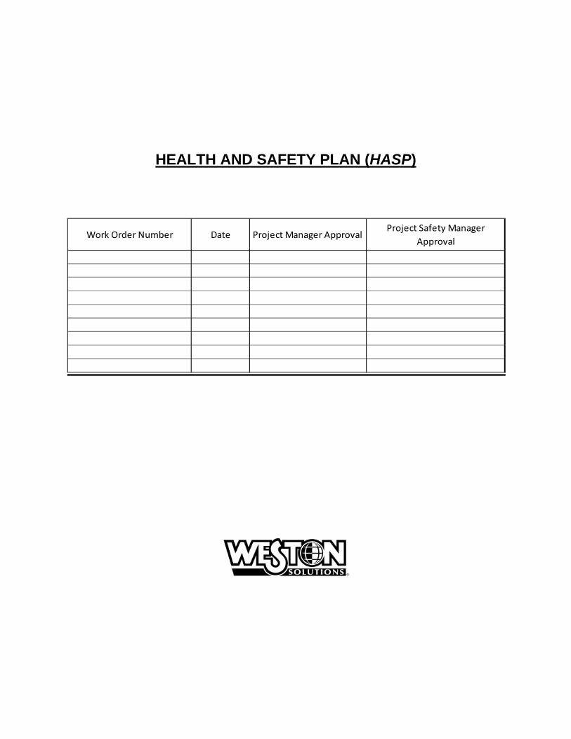
1.3.2 Subcontractor's Health and Safety Program Evaluation Name of Subcontractor: TBD Address:
Activities To Be Conducted by Subcontractor:
Evaluation Criteria Medical Program meets OSHA/WESTON criteria
Acceptable
Unacceptable Comments:
Personal Protective Equipment available
Acceptable
Unacceptable Comments:
On-site monitoring equipment available, calibrated, and operated properly
Acceptable
Unacceptable Comments:
Safe Working Procedures clearly specified
Acceptable
Unacceptable Comments:
Training meets OSHA/WESTON criteria
Acceptable
Unacceptable Comments:
Emergency Procedures
Acceptable
Unacceptable Comments:
Decontamination Procedures
Acceptable
Unacceptable Comments:
General Health and Safety Program evaluation
Acceptable
Unacceptable Comments:
Additional comments:
Subcontractor has agreed to and will conform to the WESTON HASP for this project.
Subcontractor will work under its own
HASP, which has been accepted by Project PM.
Evaluation Conducted by: Evaluation Source (SubTrack, etc.):
Date:
Subcontractor Certifications for all subcontractor personnel will be added to the HASP prior to beginning work.
Name:
Title:
Task(s):
Certification Level or Description:
Name:
Title:
Task(s):
Certification Level or Description:
Medical Current
Fit Test Current (Qual.)
Training Current
Fit Test Current (Quant.)
Medical Current
Fit Test Current (Qual.)
Training Current
Fit Test Current (Quant.)
Name:
Title:
Task(s):
Certification Level or Description:
Name:
Title:
Task(s):
Certification Level or Description:
Medical Current
Fit Test Current (Qual.)
Training Current
Fit Test Current (Quant.)
Medical Current
Fit Test Current (Qual.)
Training Current
Fit Test Current (Quant.)
June 2014
The information contained in this document is the property of Weston Solutions, Inc. and may not be used or reproduced in any form without the written permission of Weston Solutions, Inc.
2-1
2. HEALTH AND SAFETY EVALUATION

June 2014
The information contained in this document is the property of Weston Solutions, Inc. and may not be used or reproduced in any form without the written permission of Weston Solutions, Inc.
2-2
2.1 HEALTH AND SAFETY EVALUATION 2.1.1 Task Hazard Assessment
Background Review: X Complete Partial If partial why? N/A
Activities Covered Under This Plan: No. Task/Subtask Description Schedule1 Soil sampling A combination of soil boring and surface sampling. 2014 2 Groundwater
investigation Installation of groundwater monitoring wells and
groundwater sampling 2014
Types of Hazards: Numbers refer to one of the following hazard evaluation forms. Complete hazard evaluation forms for each appropriate hazard class.
Physiochemical 1
Flammable
Explosive
Corrosive
Reactive
Chemically Toxic 1
Inhalation Carcinogen
Ingestion Mutagen
Contact Teratogen
Absorption
Radiation 3
Ionizing:
Internal exposure
External exposure
Biological 2
Etiological Agent
Other (plant, insect, animal)
O2 Rich
O2 Deficient
OSHA 1910.1000 Substance (Air Contaminants)
Non-ionizing:
UV IR
Physical Hazards 4
Characterization Activities
OSHA Specific Hazard Substance Standard (Refer to following page for listing)
RF MicroW
Laser
Source/Location of Contaminants and Hazardous Substances:
Directly Related to Tasks
Air
Other Surface
Groundwater
Soil
Surface Water
Sanitary Wastewater
Process Wastewater
Other
Indirectly Related to Tasks — Nearby Process(es) That Could Affect Team Members:
WESTON Work Location
Nearby Non-Client Facility
Describe:
Have activities (task[s]) been coordinated with facility?
Comments:

June 2014
The information contained in this document is the property of Weston Solutions, Inc. and may not be used or reproduced in any form without the written permission of Weston Solutions, Inc.
2-3
HEALTH AND SAFETY EVALUATION
2.1.2 Chemical Hazards of Concern
N/A Chemical Contaminants of Concern Attach data sheets from an acceptable source such as NIOSH pocket guide, condensed chemical dictionary, ACGIH TLV booklet, Hazardous Substances Data base (HSDB), etc. List chemicals and concentrations below and locate data sheets in Attachment A of this HASP.
N/A Identify hazardous materials used or on-site and attach Safety Data Sheets (SDSs) for all reagent type chemicals, solutions, or other identified materials that in normal use in performing tasks related to this project could produce hazardous substances. Ensure that all subcontractors and other parties working nearby are informed of the presence of these chemicals and the location of the SDSs. Obtain from subcontractors and other parties, lists of the hazardous materials they use or have on-site and identify location of the SDSs here. List chemicals and quantities below and locate SDSs in Attachment B of this HASP.
Chemical Name Concentration ( )
Chemical Name Quantity
Arsenic Lead Cadmium
OSHA-SPECIFIC HAZARDOUS SUBSTANCES 1910.1001 Asbestos 1910.1002 Coal tar pitch volatiles 1910.1003 4-Nitrobiphenyl, etc. 1910.1004 alpha-Naphthylamine
1910.1005 [Reserved] 1910.1006 Methyl chloromethyl ether 1910.1007 3,3'-Dichlorobenzidine (and its salts) 1910.1008 bis-Chloromethyl ether
1910.1009 beta-Naphthylamine 1910.1010 Benzidine 1910.1011 4-Aminodiphenyl 1910.1012 Ethyleneimine
1910.1013 beta-Propiolactone 1910.1014 2-Acetylaminofluorene 1910.1015 4-Dimethylaminoazobenzene 1910.1016 N-Nitrosodimethylamine
1910.1017 Vinyl chloride 1910.1018 Inorganic arsenic 1910.1025 Lead (Att. FLD# 46) 1910.1026 Chromium VI (att. FLD 53)
1910.1027 Cadmium (Att. 50 FLD) 1910.1028 Benzene (Att. FLD# 54 or 61) 1910.1029 Coke oven emissions 1910.1043 Cotton dust
1910.1044 1,2-Dibromo-3-chloropropane 1910.1045 Acrylonitrile 1910.1047 Ethylene oxide 1910.1048 Formaldehyde
1910.1050 Methylenedianiline 1910.1051 1,3 Butadiene 1910.1052 Methylene chloride 1926.60 Methylenedianiline
1926.62 Lead 1926.1101 Asbestos (Att. FLD 52) 1926.1127 Cadmium
June 2014
The information contained in this document is the property of Weston Solutions, Inc. and may not be used or reproduced in any form without the written permission of Weston Solutions, Inc.
2-4
HEALTH AND SAFETY EVALUATION
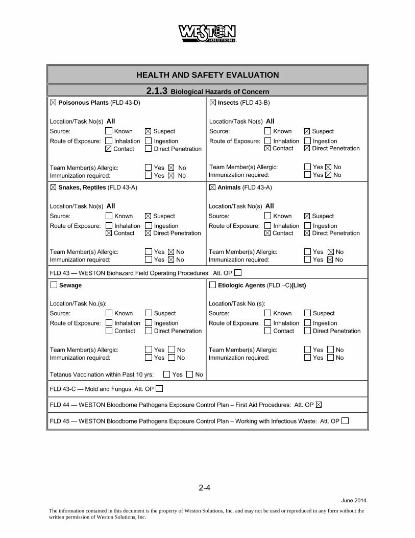
2.1.3 Biological Hazards of Concern Poisonous Plants (FLD 43-D)
Location/Task No(s) All Source: Known Suspect
Route of Exposure: Inhalation Ingestion Contact Direct Penetration
Team Member(s) Allergic: Yes No Immunization required: Yes No
Insects (FLD 43-B)
Location/Task No(s) All Source: Known Suspect
Route of Exposure: Inhalation Ingestion Contact Direct Penetration
Team Member(s) Allergic: Yes No Immunization required: Yes No
Snakes, Reptiles (FLD 43-A)
Location/Task No(s) All Source: Known Suspect
Route of Exposure: Inhalation Ingestion Contact Direct Penetration
Team Member(s) Allergic: Yes No Immunization required: Yes No
Animals (FLD 43-A)
Location/Task No(s) All Source: Known Suspect
Route of Exposure: Inhalation Ingestion Contact Direct Penetration
Team Member(s) Allergic: Yes No Immunization required: Yes No
FLD 43 — WESTON Biohazard Field Operating Procedures: Att. OP
Sewage
Location/Task No.(s):
Source: Known Suspect
Route of Exposure: Inhalation Ingestion Contact Direct Penetration
Team Member(s) Allergic: Yes No Immunization required: Yes No
Tetanus Vaccination within Past 10 yrs: Yes No
Etiologic Agents (FLD –C)(List)
Location/Task No.(s):
Source: Known Suspect
Route of Exposure: Inhalation Ingestion Contact Direct Penetration
Team Member(s) Allergic: Yes No Immunization required: Yes No
FLD 43-C — Mold and Fungus. Att. OP
FLD 44 — WESTON Bloodborne Pathogens Exposure Control Plan – First Aid Procedures: Att. OP
FLD 45 — WESTON Bloodborne Pathogens Exposure Control Plan – Working with Infectious Waste: Att. OP

June 2014
The information contained in this document is the property of Weston Solutions, Inc. and may not be used or reproduced in any form without the written permission of Weston Solutions, Inc.
2-5
HEALTH AND SAFETY EVALUATION
2.1.4 Radiation Hazards of Concern NONIONIZING RADIATION
Task No.
Type of Nonionizing Radiation
Source On-Site
TLV/PEL
Wavelength Range
Control Measures
Monitoring Instrument
1 Ultraviolet Solar Appropriate
clothing/ sunscreen
None
Infrared
Radio Frequency
Microwave
Laser
IONIZING RADIATION DAC (µCii/mL) Task No.
Radionuclide
Major Radiations
Radioactive Half-Life (Years)
D
W
Y
Surface Contamination Limit
Monitoring Instrument
June 2014
The information contained in this document is the property of Weston Solutions, Inc. and may not be used or reproduced in any form without the written permission of Weston Solutions, Inc.
2-6
HEALTH AND SAFETY EVALUATION
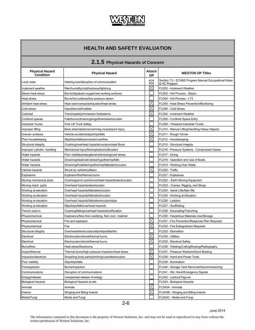
2.1.5 Physical Hazards of Concern Physical Hazard
Condition Physical Hazard Attach OP
WESTON OP Titles
Loud noise Hearing loss/disruption of communication Section 7.0 - ECH&S Program Manual Occupational Noise & HC Program
Inclement weather Rain/humidity/cold/ice/snow/lightning FLD02 - Inclement Weather
Steam heat stress Burns/displaced oxygen/wet working surfaces FLD03 - Hot Process - Steam
Heat stress Burns/hot surfaces/low pressure steam FLD04 - Hot Process - LT3
Ambient heat stress Heat rash/cramps/exhaustion/heat stroke FLD05 - Heat Stress Prevention/Monitoring
Cold stress Hypothermia/frostbite FLD06 - Cold Stress
Cold/wet Trench/paddy/immersion foot/edema FLD02 - Inclement Weather
Confined spaces Falls/burns/drowning/engulfment/electrocution FLD08 - Confined Space Entry
Industrial Trucks Fork Lift Truck Safety FLD09 – Powered Industrial Trucks
Improper lifting Back strain/abdomen/arm/leg muscle/joint injury FLD10 - Manual Lifting/Handling Heavy Objects
Uneven surfaces Vehicle accidents/slips/trips/falls FLD11 - Rough Terrain
Poor housekeeping Slips/trips/falls/punctures/cuts/fires FLD12 - Housekeeping
Structural integrity Crushing/overhead hazards/compromised floors FLD13 - Structural Integrity
Improper cylinder. handling Mechanical injury/fire/explosion/suffocation FLD16 - Pressure Systems - Compressed Gases
Water hazards Poor visibility/entanglement/drowning/cold stress FLD17 - Diving
Water hazards Drowning/heat/cold stress/hypothermia/falls FLD18 - Operation and Use of Boats
Water hazards Drowning/frostbite/hypothermia/falls/electrocution FLD19 - Working Over Water
Vehicle hazards Struck by vehicle/collision FLD20 - Traffic
Explosions Explosion/fire/thermal burns FLD21 - Explosives
Moving mechanical parts Crushing/pinch points/overhead hazards/electrocution FLD22 – Earth Moving Equipment
Moving mech. parts Overhead hazards/electrocution FLD23 – Cranes, Rigging, and Slings
Working at elevation Overhead hazards/falls/electrocution FLD24 - Aerial Lifts/Man lifts
Working at elevation Overhead hazards/falls/electrocution FLD25 - Working at Elevation
Working at elevation Overhead hazards/falls/electrocution/slips FLD26 - Ladders
Working at elevation Slips/trips/falls/overhead hazards FLD27 - Scaffolding
Trench cave-in Crushing/falling/overhead hazards/suffocation FLD28 - Excavating/Trenching
Physiochemical Explosions/fires from oxidizing, flam./corr. material FLD30 - Hazardous Materials Use/Storage
Physiochemical Fire and explosion FLD31 - Fire Prevention/Response Plan Required
Physiochemical Fire FLD32 - Fire Extinguishers Required
Structural integrity Overhead/electrocution/slips/trips/falls/fire FLD33 - Demolition
Electrical Electrocution/shock/thermal burns FLD34 - Utilities
Electrical Electrocution/shock/thermal burns FLD35 - Electrical Safety
Burns/fires Heat stress/fires/burns FLD36 - Welding/Cutting/Brazing/Radiography
Impact/thermal Thermal burns/high pressure impaction/heat stress FLD37 - Pressure Washers/Sand Blasting
Impaction/electrical Smashing body parts/pinching/cuts/electrocution FLD38 - Hand and Power Tools
Poor visibility Slips/trips/falls FLD39 - Illumination
Fire/explosion Burns/impaction FLD40 - Storage Tank Removal/Decommissioning
Communications Disruption of communications FLD41 - Std. Hand/Emergency Signals
Energy/release Unexpected release of energy FLD42 - Lockout/Tag-out
Biological Hazards Biological Hazards at site FLD43 - Biological Hazards
Animals Animals FLD43A - Animals
Insects Stinging and Biting Insects FLD43B - Stinging and Biting Insects
Molds/Fungi Molds and Fungi FLD43C - Molds and Fungi
June 2014
The information contained in this document is the property of Weston Solutions, Inc. and may not be used or reproduced in any form without the written permission of Weston Solutions, Inc.
2-7
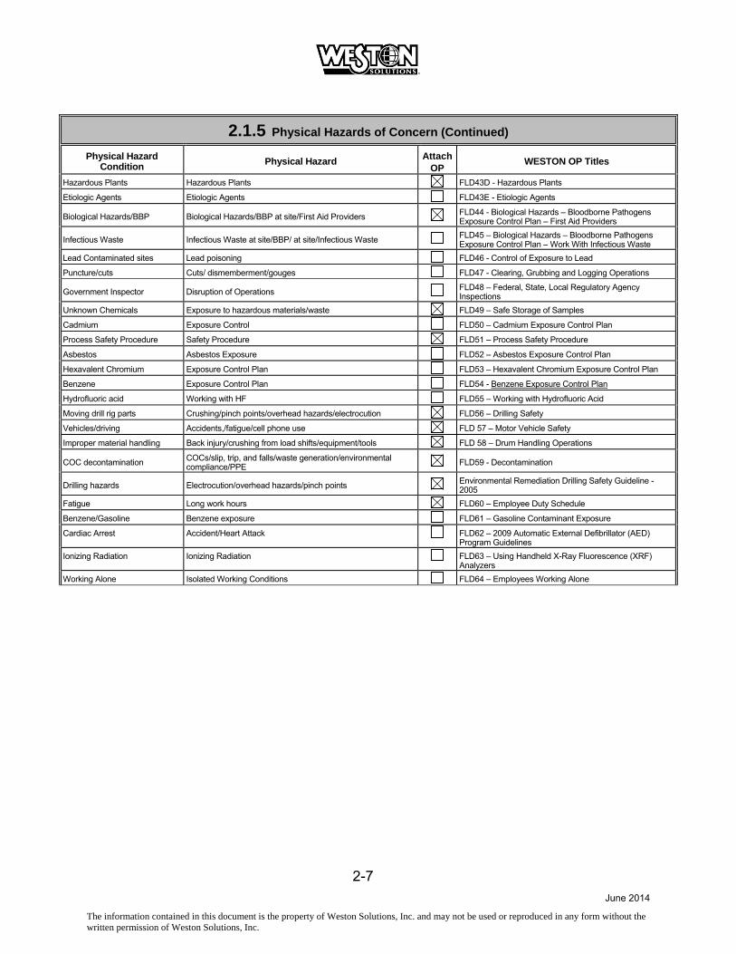
2.1.5 Physical Hazards of Concern (Continued) Physical Hazard
Condition Physical Hazard Attach OP
WESTON OP Titles
Hazardous Plants Hazardous Plants FLD43D - Hazardous Plants
Etiologic Agents Etiologic Agents FLD43E - Etiologic Agents
Biological Hazards/BBP Biological Hazards/BBP at site/First Aid Providers FLD44 - Biological Hazards – Bloodborne Pathogens Exposure Control Plan – First Aid Providers
Infectious Waste Infectious Waste at site/BBP/ at site/Infectious Waste FLD45 – Biological Hazards – Bloodborne Pathogens Exposure Control Plan – Work With Infectious Waste
Lead Contaminated sites Lead poisoning FLD46 - Control of Exposure to Lead
Puncture/cuts Cuts/ dismemberment/gouges FLD47 - Clearing, Grubbing and Logging Operations
Government Inspector Disruption of Operations FLD48 – Federal, State, Local Regulatory Agency Inspections
Unknown Chemicals Exposure to hazardous materials/waste FLD49 – Safe Storage of Samples
Cadmium Exposure Control FLD50 – Cadmium Exposure Control Plan
Process Safety Procedure Safety Procedure FLD51 – Process Safety Procedure
Asbestos Asbestos Exposure FLD52 – Asbestos Exposure Control Plan
Hexavalent Chromium Exposure Control Plan FLD53 – Hexavalent Chromium Exposure Control Plan
Benzene Exposure Control Plan FLD54 - Benzene Exposure Control Plan
Hydrofluoric acid Working with HF FLD55 – Working with Hydrofluoric Acid
Moving drill rig parts Crushing/pinch points/overhead hazards/electrocution FLD56 – Drilling Safety
Vehicles/driving Accidents,/fatigue/cell phone use FLD 57 – Motor Vehicle Safety
Improper material handling Back injury/crushing from load shifts/equipment/tools FLD 58 – Drum Handling Operations
COC decontamination COCs/slip, trip, and falls/waste generation/environmental compliance/PPE
FLD59 - Decontamination
Drilling hazards Electrocution/overhead hazards/pinch points Environmental Remediation Drilling Safety Guideline - 2005
Fatigue Long work hours FLD60 – Employee Duty Schedule
Benzene/Gasoline Benzene exposure FLD61 – Gasoline Contaminant Exposure
Cardiac Arrest Accident/Heart Attack FLD62 – 2009 Automatic External Defibrillator (AED) Program Guidelines
Ionizing Radiation Ionizing Radiation FLD63 – Using Handheld X-Ray Fluorescence (XRF) Analyzers
Working Alone Isolated Working Conditions FLD64 – Employees Working Alone

June 2014
The information contained in this document is the property of Weston Solutions, Inc. and may not be used or reproduced in any form without the written permission of Weston Solutions, Inc.
3-1
3. SITE SECURITY

June 2014
The information contained in this document is the property of Weston Solutions, Inc. and may not be used or reproduced in any form without the written permission of Weston Solutions, Inc.
3-2
3.1 SITE SECURITY ASSESSMENT FORM DESCRIPTION
Site Name and Location: Number of Employees and Subcontractors on Site: Former Study Area, Corning NY TBD
Type of Work: Study Area characterization sampling activities (Soil and/or groundwater sampling)
Projected Start Date: 2014 Projected Completion Date: TBD
Are Chemicals Used or Stored That Meet DHS/CFATS Requirements? N/Ahttp://www.dhs.gov/files/programs/gc_1185909570187.shtm If Yes, Attach Plan and DHS Approvals to HASP. http://www.dhs.gov/files/programs/gc_1169501486197.shtm
SURROUNDING AREA (urban/suburban/rural; residential/commercial/industrial; traffic volume, population density, etc.Suburban, residential neighborhood with school property within Study Area limits.
THREAT INDICATORS (apparent social, economic, political, ethnic, criminal, gang related, and other risk factors) N/A
COUNTERMEASURES (Current and projected risk mitigation factors) Security Systems (Reference Site Security Checklist):
Security Procedures (Reference Site Security Checklist):
Closest police station location and contact information: Corning Police Department – 607-962-0340 1 Center Way Corning, NY 14830
Other relevant observations or information to factor into the Site Security Plan: N/A
OVERALL SECURITY ASSESSMENT (Submit “Medium” and “High” risk assessments to Corporate Security for review)Risk Level: Low Medium High Date:
Site Safety Officer: Division Safety Manager: USE ATTACHMENTS FOR ADDITIONAL COMMENTS, MAPS AND DIAGRAMS
June 2014
The information contained in this document is the property of Weston Solutions, Inc. and may not be used or reproduced in any form without the written permission of Weston Solutions, Inc.
3-3
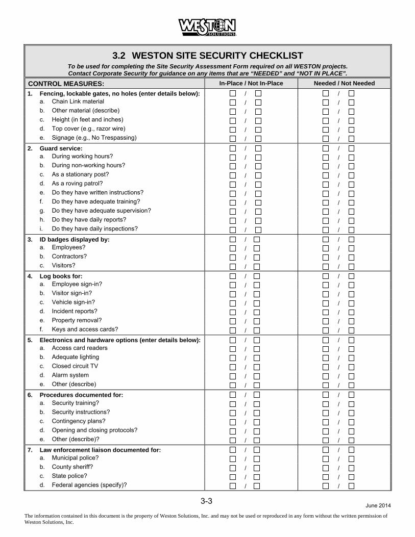
3.2 WESTON SITE SECURITY CHECKLIST To be used for completing the Site Security Assessment Form required on all WESTON projects. Contact Corporate Security for guidance on any items that are “NEEDED” and “NOT IN PLACE”.
CONTROL MEASURES: In-Place / Not In-Place Needed / Not Needed 1. Fencing, lockable gates, no holes (enter details below): / /
a. Chain Link material / / b. Other material (describe) / / c. Height (in feet and inches) / / d. Top cover (e.g., razor wire) / / e. Signage (e.g., No Trespassing) / /
2. Guard service: / / a. During working hours? / / b. During non-working hours? / / c. As a stationary post? / / d. As a roving patrol? / / e. Do they have written instructions? / / f. Do they have adequate training? / / g. Do they have adequate supervision? / / h. Do they have daily reports? / / i. Do they have daily inspections? / /
3. ID badges displayed by: / / a. Employees? / / b. Contractors? / / c. Visitors? / /
4. Log books for: / / a. Employee sign-in? / / b. Visitor sign-in? / / c. Vehicle sign-in? / / d. Incident reports? / / e. Property removal? / / f. Keys and access cards? / /
5. Electronics and hardware options (enter details below): / / a. Access card readers / / b. Adequate lighting / / c. Closed circuit TV / / d. Alarm system / / e. Other (describe) / /
6. Procedures documented for: / / a. Security training? / / b. Security instructions? / / c. Contingency plans? / / d. Opening and closing protocols? / / e. Other (describe)? / /
7. Law enforcement liaison documented for: / / a. Municipal police? / / b. County sheriff? / / c. State police? / / d. Federal agencies (specify)? / /

June 2014
The information contained in this document is the property of Weston Solutions, Inc. and may not be used or reproduced in any form without the written permission of Weston Solutions, Inc.
3-4
WESTON SITE SECURITY CHECKLIST (CONTINUED) To be used for completing the Site Security Assessment Form required on all WESTON projects. Contact Corporate Security for guidance on any items that are “NEEDED” and “NOT IN PLACE”.
CHAIN OF COMMAND: Name 24/7 Contact Information a. Security Coordinator
b. Site Supervisor
c. Project Manager
John Sontag 610-701-3679
d. PC Manager
REMARKS (use this section and supplemental pages to comment on details, exceptions or additional observations):

June 2014
The information contained in this document is the property of Weston Solutions, Inc. and may not be used or reproduced in any form without the written permission of Weston Solutions, Inc.
4-1
4. TASK BY TASK ASSESSMENT

June 2014
The information contained in this document is the property of Weston Solutions, Inc. and may not be used or reproduced in any form without the written permission of Weston Solutions, Inc.
4-2
4.1 TASK-BY-TASK RISK ASSESSMENT 4.1.1 Task 1 Description
TASK 1: Soil sampling. Includes a combination of soil boring and surface soil sampling.
EQUIPMENT REQUIRED/USED Geoprobe and/or Hollow-stem auger rig
Hand tools
Scoops Nitrile gloves Safety Boots Safety Glasses
Hearing Protection Mini Rae
Dust Monitoring
POTENTIAL HAZARDS/RISKS Chemical
Hazard Present Risk Level: H M L What justifies risk level? Sampling soil with potential metals.
Physical Hazard Present Risk Level: H M L
What justifies risk level? Work generally will occur at residential or school property, with some work in utility right-of-way areas
Biological Hazard Present Risk Level: H M L
What justifies risk level? Potential for ticks, bees, snakes, vegetation and small animals.
RADIOLOGICAL Hazard Present Risk Level: H M L
What justifies risk level?
LEVELS OF PROTECTION/JUSTIFICATION Level D
SAFETY PROCEDURES REQUIRED AND/OR FIELD OPS UTILIZED All work will be performed in accordance with the provisions of this HASP, OSHA guidelines, and WESTON Standard Operating Procedures. FLD 02, 05, 06, 10,11, 12, 13, 20, 22, 28, 34, 37, 38, 41, 43, 47, 56, 57, 59, 60, Section 7.0, Environmental Remediation Drilling Safety Guidance – 2005.

June 2014
The information contained in this document is the property of Weston Solutions, Inc. and may not be used or reproduced in any form without the written permission of Weston Solutions, Inc.
4-3
TASK-BY-TASK RISK ASSESSMENT (Continued) 4.1.2 Task 2 Description
TASK 2: Groundwater sampling activities, includes the installation of groundwater monitoring wells and groundwater sampling
EQUIPMENT REQUIRED/USED Hollow-stem auger Rig Nitrile Gloves
Hand Tools Sample Bottles
Dust Monitoring
Safety Boots Water Level Indicator Safety Glasses Groundwater Pumps Hearing Protection Bailers MiniRae Tubing
POTENTIAL HAZARDS/RISKS Chemical
Hazard Present Risk Level: H M L What justifies risk level? Ground water sampling with potential constituents at lower levels
Physical Hazard Present Risk Level: H M L
What justifies risk level? Work generally will occur at residential or school property, with some work possibly in utility right-of-way areas
Biological Hazard Present Risk Level: H M L
What justifies risk level? Potential for ticks, bees, snakes, vegetation and small animals.
RADIOLOGICAL Hazard Present Risk Level: H M L
What justifies risk level?
LEVELS OF PROTECTION/JUSTIFICATION Level D
SAFETY PROCEDURES REQUIRED AND/OR FIELD OPS UTILIZED All work will be performed in accordance with the provisions of this HASP, OSHA guidelines, and WESTON Standard Operating Procedures. FLD 01, 02, 05, 06, 10, 11, 12, 17, 18, 19, 20, 32, 34, 35, 36, 37, 41, 43, 47, 57, 59, 60 Section 7.0, Environmental Remediation Drilling Safety Guidance – 2005.
June 2014
The information contained in this document is the property of Weston Solutions, Inc. and may not be used or reproduced in any form without the written permission of Weston Solutions, Inc.
4-4
4.1 TASK-BY-TASK RISK ASSESSMENT (Continued) 4.1.3 Task 3 Description
EQUIPMENT REQUIRED/USED
POTENTIAL HAZARDS/RISKS Chemical
Hazard Present Risk Level: H M L What justifies risk level?
Physical Hazard Present Risk Level: H M L
What justifies risk level?
Biological Hazard Present Risk Level: H M L
What justifies risk level?
RADIOLOGICAL Hazard Present Risk Level: H M L
What justifies risk level?
LEVELS OF PROTECTION/JUSTIFICATION
SAFETY PROCEDURES REQUIRED AND/OR FIELD OPS UTILIZED All work will be performed in accordance with the provisions of this HASP, OSHA guidelines, and WESTON Standard Operating Procedures.

June 2014
The information contained in this document is the property of Weston Solutions, Inc. and may not be used or reproduced in any form without the written permission of Weston Solutions, Inc.
4-5
4.2 PERSONNEL PROTECTION PLANEngineering Controls Describe Engineering Controls used as part of Personnel Protection Plan:
Task(s) Tasks 1-2 Administrative Controls Describe Administrative Controls used as part of Personnel Protection Plan:
Task(s) Tasks 1-2 All Conduct hazard analysis of all work tasks. All Conduct safety briefings with contractors prior to performing daily tasks to discuss safety hazards and controls Taken to minimize or eliminate hazards Personal Protective Equipment Action Levels for Changing Levels of Protection. Refer to Site Air Monitoring Program—Action Levels. Define Action Levels for up or down grade for each task:
Task(s) Tasks 1-2 All Hard hat, safety glasses, safety shoes, hearing protection (as necessary) All PPE will be reviewed with each hazard analysis to ensure level of PPE is appropriate for scope of work
Description of Levels of Protection
Level D Level D Modified
Task(s): All Task(s): NA
Head Hard hat when near drilling rig Head
Eye and Face Safety Glasses Eye and Face
Hearing Ear plugs in designated areas Hearing
Arms and Legs Only Arms and Legs Only
Appropriate Work Uniform Coveralls or long pants and appropriate shirt Whole Body
Hand – Gloves Nitrile (as needed) Apron
Foot - Safety Boots Steel-toed boots Hand - Gloves
Fall Protection Gloves
Flotation Gloves
Other Foot - Safety Boots
Over Boots

June 2014
The information contained in this document is the property of Weston Solutions, Inc. and may not be used or reproduced in any form without the written permission of Weston Solutions, Inc.
4-6
4.3 DESCRIPTION OF LEVELS OF PROTECTION Level C Level B ( ) or Level A ( )
Task(s): NA Task(s): NA
Head
Head
Eye and Face
Eye and Face
Hearing
Hearing
Arms and Legs Only
Arms and Legs Only
Whole Body
Whole Body
Apron
Apron
Hand – Gloves
Hand - Gloves
Gloves
Gloves
Gloves
Gloves
Foot - Safety Boots
Foot - Safety Boots
Outer Boots
Outer Boots
Boots (Other)
Boots (Other)
Half Face
SAR - Airline
Cart./Canister
SCBA
Full Face
Comb. Airline/SCBA
Cart./Canister
Cascade System
PAPR
Compressor
Cart./Canister
Fall Protection
Type C
Flotation
Fall Protection
Other
Flotation
Other

June 2014
The information contained in this document is the property of Weston Solutions, Inc. and may not be used or reproduced in any form without the written permission of Weston Solutions, Inc.
5-1
5. MONITORING PROGRAM

June 2014
The information contained in this document is the property of Weston Solutions, Inc. and may not be used or reproduced in any form without the written permission of Weston Solutions, Inc.
5-2
5.1 SITE OR PROJECT HAZARD MONITORING PROGRAM 5.1.1 Air Monitoring Instruments
Instrument Selection and Initial Check Record Reporting Format: Field Notebook Field Data Sheets* Air Monitoring Log Trip
Report Other
Instrument
Task
No.(s)
Number
Required
Number
Received
Checked Upon
Receipt
Comment
Initials
RAD
GM (Pancake)
NaI (Micro R)
ZnS (Alpha Scintillator)
Other
PID
MiniRAE 1, 2
MultiRAE (LEL/O2/H2S/CO/PID)
TVA 1000 (PID/FID)
Other
FID
TVA 1000 (FID/PID)
Other
PDR 1000 (Particulate) 1, 2
Single Gas Meter (SGM)
Specify Chemical:
Personal Sampling Pump
Specify Media:
Bio-Aerosol Monitor
Tubes/type:
Tubes/type:
Tubes/type:
Tubes/type:

June 2014
The information contained in this document is the property of Weston Solutions, Inc. and may not be used or reproduced in any form without the written permission of Weston Solutions, Inc.
5-3
5.1 SITE OR PROJECT HAZARD MONITORING PROGRAM 5.1.1 Air Monitoring Instruments Calibration Record
Instrument, Mfg.,
Model, Equip. ID No.
Date
Time
Calib. Material
Calib.
MethodMfg.'s
Other
Initial
Setting and Reading
Final
Setting and Reading
Calibrator's Initials

June 2014
The information contained in this document is the property of Weston Solutions, Inc. and may not be used or reproduced in any form without the written permission of Weston Solutions, Inc.
5-4
5.2 SITE AIR MONITORING PROGRAM Action Levels
These Action Levels, if not defined by regulation, are some percent (usually 50%) of the applicable PEL/TLV/REL. That number must also be adjusted to account for
instrument response factors.
Tasks Action Level Action
Explosive or Flammable Atmosphere
Ambient Air Concentration
Confined Space Concentration
<10% LEL 0 to 1% LEL Work may continue. Consider toxicity potential.
10 to 25% LEL >25% LEL
1 to 10% LEL >10% LEL
Work may continue. Increase monitoring frequency. Work must stop. Ventilate area before returning.
Oxygen Ambient Air Concentration
Confined Space Concentration
<19.5% O2 <19.5% O2 Leave area. Re-enter only with self-contained breathing apparatus.
19.5% to 25% O2
19.5% to 23.5% O2
Work may continue. Investigate changes from 21%.
>25% O2 >23.5% O2 Work must stop. Ventilate area before returning.
Radiation 3, Radiation screening related to XRF to be performed by selected subcontractor for XRF work
< 3 times background Continue work.
3 times background to < 1 mR/hour
Radiation above background levels (normally 0.01-0.02 mR/hr) signifies possible radiation source(s) present. Continue investigation with caution. Perform thorough monitoring. Consult with a Health Physicist.
> 1 mrem/hour Potential radiation hazard. Evacuate site. Continue investigation only upon the advice of Health Physicist.
Organic Gases and Vapors
1, 2 1.0 units sustained Increase monitoring frequency. Stop work and evaluate appropriate PPE
Inorganic Gases, Vapors, and Particulates
1, 2 100 µg/m3 above background per 15-minute period
Continue work with dust suppression techniques. If levels exceed 150 µg/m3 above background per 15-minute period. Stop work and re-evaluate dust suppression.

June 2014
The information contained in this document is the property of Weston Solutions, Inc. and may not be used or reproduced in any form without the written permission of Weston Solutions, Inc.
5-5
5.3 ACTION LEVELS
(Attach action level calculations)

June 2014
The information contained in this document is the property of Weston Solutions, Inc. and may not be used or reproduced in any form without the written permission of Weston Solutions, Inc.
6-1
6. HOSPITAL INFORMATION

June 2014
The information contained in this document is the property of Weston Solutions, Inc. and may not be used or reproduced in any form without the written permission of Weston Solutions, Inc.
6-2
6.1 CONTINGENCIES 6.1.1 Emergency Contacts and Phone Numbers
Agency Contact Phone Number
WorkCare WESTON Medical Director
WorkCare WESTON Program Administrator
Dr. Peter Greaney
Heather Lind
From 6 am to 4:30 pm Pacific Time call 800-455-6155 and dial 0 for the Operator or ext. 475 for Heather Lind to request the on-call clinician.
After-Business Hours Contact (In Case of Emergency Only)
4:31 p.m. – 5:59 a.m. Pacific Time, all day Saturday, Sunday, and Holidays call 800-455-6155 Dial 3 to reach the after-hours answering service. Request that the service connect you with the on-call clinician or the on-call clinician
will return your call within 30 minutes.
WESTON Corporate Environmental Health & Safety Director
James Davis (251) 434-6420 - (334) 319-0380 (cell)
WESTON Medical Programs Manager William Irwin (610) 701-3684 - (267) 918-8371 (cell)
WESTON Health & Safety Division Safety Manager George Crawford (610) 701-3771 - (484) 437-5976 (Cell)
WESTON Health & Safety Local Safety Officer George Crawford (610) 701-3771- (484) 437-5976 (Cell)
Fire Department 911
Police Department 911
WESTON FSO Cell Phone
WESTON PM Cell Phone John Sontag (610) 701-3679
Client Site Phone
Site Telephone
Nearest Telephone
Poison Control (800) 222-1222 Local Medical Emergency Facility(s) - LMF
Name of Hospital: Guthrie Corning Hospital
Address: 176 Denison Pkwy E, Corning, NY 14830 Phone No.: 607-937-7200
Name of Contact: Phone No.: Type of Service: X Physical trauma only
Chemical exposure only
Physical trauma and chemical exposure
Available 24 hours
Route to Hospital: (See Attached)
Travel time from site: 4 Minutes
Distance to hospital: 0.8 Miles Name/no. of 24-hr ambulance service: 911

June 2014
The information contained in this document is the property of Weston Solutions, Inc. and may not be used or reproduced in any form without the written permission of Weston Solutions, Inc.
6-3
Secondary or Specialty Service Provider
Name of Hospital:
Address: Phone No.:
Name of Contact: Phone No.:
Type of Service: Physical trauma only
Chemical exposure only
Physical trauma and chemical exposure
Available 24 hours
Route to Hospital (see attached):
Travel time from site: Distance to hospital: Name/no. of 24-hr ambulance service: /
See reporting an incident in Attachment F.

June 2014
The information contained in this document is the property of Weston Solutions, Inc. and may not be used or reproduced in any form without the written permission of Weston Solutions, Inc.
6-4
6.1.2 Hospital Map
This map is subject to Google’s Terms of Service, and Google is the owner of rights therein. Portions of this image may have been removed for clarity.
June 2014
The information contained in this document is the property of Weston Solutions, Inc. and may not be used or reproduced in any form without the written permission of Weston Solutions, Inc.
6-5
6.1 CONTINGENCIES
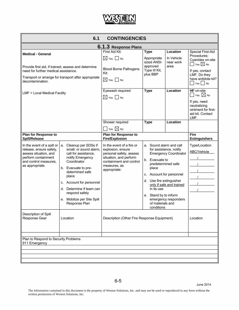
6.1.3 Response Plans Medical - General
Provide first aid, if trained; assess and determine need for further medical assistance.
Transport or arrange for transport after appropriate decontamination.
First Aid Kit:
Yes No
Blood Borne Pathogens Kit:
Yes No
Type
Appropriate sized ANSI-approved Type III Kit, plus BBP
Location
In Vehicle near work area
Special First-Aid Procedures: Cyanides on-site
Yes No
If yes, contact LMF. Do they have antidote kit?
Yes No
LMF = Local Medical Facility Eyewash required
Yes No
Type
Location
HF on-site Yes No
If yes, need neutralizing ointment for first-aid kit. Contact LMF.
Shower required
Yes No
Type
Location
Plan for Response to Spill/Release
Plan for Response to Fire/Explosion
Fire Extinguishers
In the event of a spill or release, ensure safety, assess situation, and perform containment and control measures, as appropriate.
a. Cleanup per SDSs if small; or sound alarm, call for assistance, notify Emergency Coordinator
b. Evacuate to pre- determined safe place
c. Account for personnel
d. Determine if team can respond safely
e. Mobilize per Site Spill Response Plan
In the event of a fire or explosion, ensure personal safety, assess situation, and perform containment and control measures, as appropriate:
a. Sound alarm and call for assistance, notify Emergency Coordinator
b. Evacuate to predetermined safe place
c. Account for personnel
d. Use fire extinguisher only if safe and trained in its use
e. Stand by to inform emergency responders of materials and conditions
Type/Location
ABC/Vehicle
/
/
/
/
/
/
Description of Spill Response Gear
Location
Description (Other Fire Response Equipment)
Location
Plan to Respond to Security Problems 911 Emergency
June 2014
The information contained in this document is the property of Weston Solutions, Inc. and may not be used or reproduced in any form without the written permission of Weston Solutions, Inc.
7-1
7. DECONTAMINATION PLAN
June 2014
The information contained in this document is the property of Weston Solutions, Inc. and may not be used or reproduced in any form without the written permission of Weston Solutions, Inc.
7-2
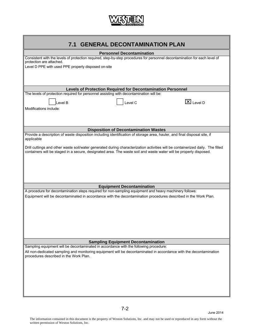
7.1 GENERAL DECONTAMINATION PLAN Personnel Decontamination
Consistent with the levels of protection required, step-by-step procedures for personnel decontamination for each level of protection are attached. Level D PPE with used PPE properly disposed on-site
Levels of Protection Required for Decontamination Personnel The levels of protection required for personnel assisting with decontamination will be:
Level B Level C Level D
Modifications include:
Disposition of Decontamination Wastes Provide a description of waste disposition including identification of storage area, hauler, and final disposal site, if applicable Drill cuttings and other waste soil/water generated during characterization activities will be containerized daily. The filled containers will be staged in a secure, designated area. The waste soil and waste water will be properly disposed.
Equipment Decontamination A procedure for decontamination steps required for non-sampling equipment and heavy machinery follows:
Equipment will be decontaminated in accordance with the decontamination procedures described in the Work Plan.
Sampling Equipment Decontamination Sampling equipment will be decontaminated in accordance with the following procedure:
All non-dedicated sampling and monitoring equipment will be decontaminated in accordance with the decontamination procedures described in the Work Plan.

June 2014
The information contained in this document is the property of Weston Solutions, Inc. and may not be used or reproduced in any form without the written permission of Weston Solutions, Inc.
7-3
7.2 LEVEL D DECONTAMINATION PLAN Check indicated functions or add steps, as necessary: Function Description of Process, Solution, and Container
Segregated equipment drop
Boot cover and glove wash
Boot cover and glove rinse
Tape removal - outer glove and boot
Boot cover removal
Outer glove removal
HOTLINE Suit/safety boot wash
Suit/boot/glove rinse
Safety boot removal
Suit removal
Inner glove wash
Inner glove rinse
Inner glove removal
Inner clothing removal
CONTAMINATION REDUCTION ZONE (CRZ)/SAFE ZONE BOUNDARY Field wash
Redress
Disposal Plan, End of Day:
Disposal Plan, End of Week:
Disposal Plan, End of Project:

June 2014
The information contained in this document is the property of Weston Solutions, Inc. and may not be used or reproduced in any form without the written permission of Weston Solutions, Inc.
7-4
7.3 LEVEL C DECONTAMINATION PLAN Check indicated functions or add steps, as necessary: Function Description of Process, Solution, and Container
Segregated equipment drop
Boot cover and glove wash
Boot cover and glove rinse
Tape removal - outer glove and boot
Boot cover removal
Outer glove removal
HOTLINE Suit/safety boot wash
Suit/boot/glove rinse
Safety boot removal
Suit removal
Inner glove wash
Inner glove rinse
Face piece removal
Inner glove removal
Inner clothing removal
CONTAMINATION REDUCTION ZONE (CRZ)/SAFE ZONE BOUNDARY Field wash
Redress
Disposal Plan, End of Day:
Disposal Plan, End of Week:
Disposal Plan, End of Project:

June 2014
The information contained in this document is the property of Weston Solutions, Inc. and may not be used or reproduced in any form without the written permission of Weston Solutions, Inc.
7-5
7.4 LEVEL B ( ) or Level A ( ) DECONTAMINATION PLAN Check indicated functions or add steps, as necessary: Function Description of Process, Solution, and Container
Segregated equipment drop
Boot cover and glove wash
Boot cover and glove rinse
Tape removal - outer glove and boot
Boot cover removal
Outer glove removal
HOTLINE Suit/safety boot wash
Suit/SCBA/boot/glove rinse
Safety boot removal
Remove SCBA backpack without disconnecting
Splash suit removal
Inner glove wash
Inner glove rinse
SCBA disconnect and face piece removal
Inner glove removal
Inner clothing removal
CONTAMINATION REDUCTION ZONE (CRZ)/SAFE ZONE BOUNDARY Field wash
Redress
Disposal Plan, End of Day:
Disposal Plan, End of Week:
Disposal Plan, End of Project:

June 2014
The information contained in this document is the property of Weston Solutions, Inc. and may not be used or reproduced in any form without the written permission of Weston Solutions, Inc.
8-1
8. TRAINING AND BRIEFING TOPICS/SIGN OFF SHEET

June 2014
The information contained in this document is the property of Weston Solutions, Inc. and may not be used or reproduced in any form without the written permission of Weston Solutions, Inc.
8-2
8.1 TRAINING AND BRIEFING TOPICS The following items will be covered at the site-specific training meeting, daily or periodically.
Site characterization and analysis, Sec. 3.0, 29 CFR 1910.120 I
Level A
Physical hazards Level B
Chemical hazards Level C
Animal bites, stings, and poisonous plants Level D
Etiologic (infectious) agents Monitoring, 29 CFR 1910.120 (h)
Site control, 29 CFR 1910.120 d Decontamination, 29 CFR 1910.120 (k)
Engineering controls and work practices, 29 CFR 1910.120 (g)
Emergency response, 29 CFR 1910.120 (l)
Heavy machinery Elements of an emergency response, 29 CFR 1910.120 (l)
Forklift Procedures for handling site emergency incidents, 29 CFR 1910.120 (l)
Backhoe Off-site emergency response, 29 CFR 1910.120 (l)
Equipment Handling drums and containers, 29 CFR 1910.120 (j)
Tools Opening drums and containers
Ladder, 29 CFR 1910.25.26.26 + 29 CFR 1926.1053 Electrical material handling equipment
Overhead and underground utilities Radioactive waste
Scaffolds Shock-sensitive waste
Structural integrity Laboratory waste packs
Unguarded openings - wall, floor, ceilings Sampling drums and containers
Pressurized air cylinders Shipping and transport, 49 CFR 172.101, IATA
Personal protective equipment, 29 CFR 1910.120 (g); 29 CFR 1910.134
Tank and vault procedures
Respiratory protection, 29 CFR 1910.120 (g); ANSI Z88.2 Illumination, 29 CFR 1926.26
Working over water FLD-19� Sanitation, 29 CFR 1926.27
Boating safety FLD-18 Proper lifting techniques
Heat Stress / Cold Stress

June 2014
The information contained in this document is the property of Weston Solutions, Inc. and may not be used or reproduced in any form without the written permission of Weston Solutions, Inc.
8-3
8.2 HEALTH AND SAFETY PLAN APPROVAL/SIGNOFF FORM Site Name: Study Area, Corning, New York WO#: 02005.056.001.0001
Address: Located in Corning, New York on the north bank of the Chemung River (see Figure 1).
I understand, agree to, and will conform with the information set forth in this Health and Safety Plan (and attachments) and discussed in the personnel health and safety briefing(s).
Name Signature Date
June 2014
The information contained in this document is the property of Weston Solutions, Inc. and may not be used or reproduced in any form without the written permission of Weston Solutions, Inc.
ATTACHMENT A CHEMICAL CONTAMINANTS DATA SHEETS
June 2014
The information contained in this document is the property of Weston Solutions, Inc. and may not be used or reproduced in any form without the written permission of Weston Solutions, Inc.
ATTACHMENT B SAFETY DATA SHEETS
(ATTACH SDS)

June 2014
The information contained in this document is the property of Weston Solutions, Inc. and may not be used or reproduced in any form without the written permission of Weston Solutions, Inc.
ATTACHMENT C
SAFETY PROCEDURES/FIELD OPERATING PROCEDURES (FLD OPS) In lieu of attaching individual copies of FLDs, the site safety officer or his designee may elect to maintain an electronic copy of the WESTON Corporate Environmental Compliance, Health, and Safety Program Manual (including all FLDs) on site in an electronic format. The most recent version of the CEHS Program Manual and supporting documents are located at: http://portal/services/EHS/SitePages/CEHSProgramElements.aspx

June 2014
The information contained in this document is the property of Weston Solutions, Inc. and may not be used or reproduced in any form without the written permission of Weston Solutions, Inc.
ATTACHMENT D HAZARD COMMUNICATION PROGRAM
June 2014
The information contained in this document is the property of Weston Solutions, Inc. and may not be used or reproduced in any form without the written permission of Weston Solutions, Inc.
SITE-SPECIFIC HAZARD COMMUNICATION PROGRAM
Location-Specific Hazard Communication Program/Checklist To ensure an understanding of and compliance with the Hazard Communication Standard, WESTON will use this checklist/document (or similar document) in conjunction with the WESTON Written Hazard Communication Program as a means of meeting site- or location-specific requirements.
While responsibility for activities within this document reference the WESTON Safety Officer (SO), it is the responsibility of all personnel to ensure compliance. Responsibilities under various conditions can be found within the WESTON Written Hazard Communication Program.
To ensure that information about the dangers of all hazardous chemicals used by WESTON is known by all affected employees, the following Hazard Communication Program has been established. All affected personnel will participate in the Hazard Communication Program. This written program, as well as WESTON’s Corporate Hazard Communication Program, will be available for review by any employee, employee representative, representative of OSHA, NIOSH, or any affected employer/employee on a multi-employer site.
Site or other location name/address: Study Area, Corning, NY
Site/Project/Location Manager: John Sontag
Site/Location Safety Officer: TBD
List of chemicals compiled, format: X HASP Other:
Location of SDS files: Attached
Training conducted by: Name: TBD Date:
Indicate format of training documentation: X Field Log: Other:
Client briefing conducted regarding hazard communication:
If multi-employer site (client, subcontractor, agency, etc.), indicate name of affected companies:
Other employer(s) notified of chemicals, labeling, and SDS information:
Has WESTON been notified of other employer’s or client’s hazard communication program(s), as necessary? Yes X No
List of Hazardous Chemicals A list of known hazardous chemicals used by WESTON personnel must be prepared and attached to this document or placed in a centrally identified location with the SDSs. Further information on each chemical may be obtained by reviewing the appropriate SDS. The list will be arranged to enable cross-reference with the SDS file and the label on the container. The SO or Location Manager is responsible for ensuring the chemical listing remains up-to-date.
Container Labeling The WESTON SO will verify that all containers received from the chemical manufacturer, importer, or distributor for use on-site are clearly labeled.
The SO is responsible for ensuring that labels are placed where required and for comparing SDSs and other information with label information to ensure correctness.

June 2014
The information contained in this document is the property of Weston Solutions, Inc. and may not be used or reproduced in any form without the written permission of Weston Solutions, Inc.
Safety Data Sheets (SDSs) The SO is responsible for establishing and monitoring WESTON’s SDS program for the location. The SO will ensure that procedures are developed to obtain the necessary SDSs and will review incoming SDSs for new or significant health and safety information. He/she will see that any new information is passed on to the affected employees. If an SDS is not received at the time of initial shipment, the SO will call the manufacturer and have an SDS delivered for that product in accordance with the requirements of WESTON’s Written Hazard Communication Program.
A log for, and copies of, SDSs for all hazardous chemicals in use will be kept in the SDS folder at a location known to all site workers. SDSs will be readily available to all employees during each work shift. If an MSDS is not available, immediately contact the WESTON SO or the designated alternate. When a revised SDS is received, the SO will immediately replace the old SDS.
Employee Training and Information The SO is responsible for the WESTON site-specific personnel training program. The SO will ensure that all program elements specified below are supplied to all affected employees.
At the time of initial assignment for employees to the work site, or whenever a new hazard is introduced into the work area, employees will attend a health and safety meeting or briefing that includes the information indicated below.
Hazardous chemicals present at the work site. Physical and health risks of the hazardous chemicals. The signs and symptoms of overexposure. Procedures to follow if employees are overexposed to hazardous chemicals. Location of the SDS file and Written Hazard Communication Program. How to determine the presence or release of hazardous chemicals in the employee’s work area. How to read labels and review SDSs to obtain hazard information. Steps WESTON has taken to reduce or prevent exposure to hazardous chemicals. How to reduce or prevent exposure to hazardous chemicals through the use of controls procedures,
work practices, and personal protective equipment. Hazardous, non-routine tasks to be performed (if any). Chemicals within unlabeled piping (if any).
Hazardous Non-routine Tasks When employees are required to perform hazardous non-routine tasks, the affected employee(s) will be given information by the SO about the hazardous chemicals he or she may use during such activity. This information will include specific chemical hazards, protective and safety measures the employee can use, and steps WESTON is using to reduce the hazards. These steps include, but are not limited to, ventilation, respirators, presence of another employee, and emergency procedures.
Chemicals in Unlabeled Pipes Work activities may be performed by employees in areas where chemicals are transferred through unlabeled pipes. Prior to starting work in these areas, the employee will contact the SO, at which time information as to the chemical(s) in the pipes, potential hazards of the chemicals or the process involved, and the safety precautions that should be taken will be determined and presented.
Multi-Employer Work Sites It is the responsibility of the SO to provide other employers with information about hazardous chemicals imported by WESTON to which their employees may be exposed, along with suggested safety precautions. It is also the responsibility of the SO and the Site Manager to obtain information about hazardous chemicals used by other employers to which WESTON employees may be exposed.

June 2014
The information contained in this document is the property of Weston Solutions, Inc. and may not be used or reproduced in any form without the written permission of Weston Solutions, Inc.
WESTON’s chemical listing will be made available to other employers, as requested. SDSs will be available for viewing, as necessary.
The location, format, and/or procedures for accessing SDS information must be relayed to affected employees.

June 2014
The information contained in this document is the property of Weston Solutions, Inc. and may not be used or reproduced in any form without the written permission of Weston Solutions, Inc.
ATTACHMENT E AIR SAMPLING DATA SHEETS

June 2014
The information contained in this document is the property of Weston Solutions, Inc. and may not be used or reproduced in any form without the written permission of Weston Solutions, Inc.
AIR MONITORING PROGRAM Field Data Sheets
Location:
Aerosol GM: Shield Probe/
Thin Window
% LEL
% O2
PID (units)
FID (units)
Monitor (mg/m3)
mR/hr
cpm
NaI (uR/hr)
ZnS (cpm)
Monitox (ppm) Detector Tube(s)
Sound Levels (dBA) Illumination pH Other Other Other Other Other Location:
Aerosol Monitor
GM: Shield Probe/ Thin Window
NaI ZnS
% LEL % O2 PID (units) FID (units) (mg/m3) mR/hr cpm (uR/hr) (cpm)
Monitox (ppm) Detector Tube(s)
Sound Levels (dBA) Illumination pH Other Other Other Other Other

June 2014
The information contained in this document is the property of Weston Solutions, Inc. and may not be used or reproduced in any form without the written permission of Weston Solutions, Inc.
AIR MONITORING/SAMPLING DATA LOG Client:
W.O. No.:
Sample No.:
Address: Sampled By:
Date:
Employee and Location Information Employee Name:
Employee No.:
Job Title:
Respirator APR ½ Mask Full Face PAPR ½ Mask Full Face Hood SAR ½ Mask Full Face Hood SCBA
Manufacturer:
Cartridge Type:
PPE: Hard Hat HPD Gloves Safety Shoes Coveralls Other:
Sampling Data Sampling Type: Personal
TWA STEL Area Source
Full Shift Partial Shift Grab
Media:
Pump Type/Serial No.: /
Calibrator/Serial No.:
/
Pre-Calibration: 1. 2. 3. avg-pre:
Post-Calibration: 1. 2. 3. avg-post:
Start Time:
Restart Time:
Restart Time:
Avg. Flow rate:
% Change:
1st Stop Time:
2nd Stop Time:
3rd Stop Time:
Total Time:
Volume:
Multiple Samples for this TWA: Yes No
Multiple Chemical Exposures: Yes No
Exposure Time: Normal Worst Case
Sampling Conditions Weather Conditions: Temp: R.H: B.P.: Other: Engineering Controls:
Substances Evaluated Substance Result Substance Result Substance Result
Observations and Comments
QA by: Date:

June 2014
The information contained in this document is the property of Weston Solutions, Inc. and may not be used or reproduced in any form without the written permission of Weston Solutions, Inc.
ATTACHMENT F INCIDENT REPORTING
June 2014
The information contained in this document is the property of Weston Solutions, Inc. and may not be used or reproduced in any form without the written permission of Weston Solutions, Inc.
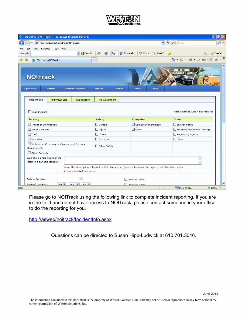
Please go to NOITrack using the following link to complete incident reporting. If you are in the field and do not have access to NOITrack, please contact someone in your office to do the reporting for you. http://asweb/noitrack/IncidentInfo.aspx
Questions can be directed to Susan Hipp-Ludwick at 610.701.3046.

June 2014
The information contained in this document is the property of Weston Solutions, Inc. and may not be used or reproduced in any form without the written permission of Weston Solutions, Inc.
ATTACHMENT G TRAFFIC CONTROL PLAN

June 2014
The information contained in this document is the property of Weston Solutions, Inc. and may not be used or reproduced in any form without the written permission of Weston Solutions, Inc.
ATTACHMENT H ENVIRONMENTAL HEALTH & SAFETY INSPECTION CHECKLIST

June 2014
The information contained in this document is the property of Weston Solutions, Inc. and may not be used or reproduced in any form without the written permission of Weston Solutions, Inc.
ENVIRONMENTAL HEALTH AND SAFETY INSPECTION CHECKLIST
Project Name:
Inspector:
Submit to:
Date:

June 2014
The information contained in this document is the property of Weston Solutions, Inc. and may not be used or reproduced in any form without the written permission of Weston Solutions, Inc.
THE WESTON SITE APPEARANCE YES NO COMMENT
Is the site secured to prevent inadvertent, unnecessary, or unauthorized access? Are gates closed and locked at any time that the access point is not occupied or visible to site workers?
Are access points posted with signs to indicate client and end-user client name, WESTON’s name and logo, names of other contractors and sub-contractors, project name and location, and appropriate safety messages?
Are required postings in place (e.g., Labor Poster, Emergency Phone Numbers, Site Map, etc.)?
Are site trailers tied down per local code and provided with stairs that have a landing platform with guard and stair railings?
Is a Site Safety file system established in the office to maintain records required by applicable safety regulations
Is the Health and Safety Plan (HASP) or Accident Prevention Plan (APP) amended as scope of work changes, hazards are discovered or eliminated or if risk change?
Is the Site Safety Plan and the Safety Officers Field Manual on site?
Is new employee indoctrination provided?
Have site Rules been provided, discussed and signed off on by all employees
Incident Reporting procedure explained to all?
Is site management trained in the WESTON (and client as applicable) Incident Reporting system?
Are NOI and Supplemental Report forms and OSHA 300 Log available on site?
Is Site Management aware of the Case Management and Incident Investigation Procedures?
Is there a list of preferred provider medical facilities available?
Has the “Inspection By A Regulatory Agency” procedure been reviewed by all site management?
Will Competent Persons be required because of activities to be performed, equipment to be used or hazards to be encountered?
POLICIES YES NO COMMENT
Each individual employee is aware that he or she responsible for complying with applicable safety requirements, wearing prescribed safety equipment and preventing avoidable accidents.
Do employees understand that they will wear clothing suitable for existing weather and work conditions and the minimum work uniform will include long pants, sleeved work shirts, protective footwear, hard hat, and safety glasses unless otherwise specified via the HASP.
Are employees provided safety and health training to enable them to perform their work safely? Is all training documented to indicate the date of the session, topics covered, and names of participants?
Safety meetings are conducted daily. The purpose of the meetings are to review past activities, review pertinent tailgate safety topics and establish safe working procedures for anticipated hazards encountered during the day.
Training has been provided to all personnel regarding handling of emergency situations that may arise from the activity or use of equipment on the project.
Employees/contractors are informed and understand that they may not be under the influence of alcohol, narcotics, intoxicants, or similar mind-altering substances at any time. Employees found under the influence of or consuming such substances will be immediately removed from the job site.
Site workers and operators of any equipment or vehicles are able to read and understand the signs, signals, and operating instructions of their use.
Have contractors performing work provided copies of relevant documentation (such as medical fit-for-duty, training certificates, fit-tests, etc.) prior to initiation of the project?

June 2014
The information contained in this document is the property of Weston Solutions, Inc. and may not be used or reproduced in any form without the written permission of Weston Solutions, Inc.
SANITATION 29 CFR 1926 Subparts C, D. EM 385-1-1, Section 2
YES NO COMMENT
Is an adequate supply of drinking water provided? Is potable/drinking water labeled as such? Are there sufficient drinking cups provided?
Are there a sufficient number of toilets?
Are washing facilities readily available and appropriate for the cleaning needs?
Are washing facilities kept sanitary with adequate cleansing and drying materials?
Waste is secured so as not to attract rodents, insects, or other vermin?
Is an effective housekeeping program established and implemented?
ACCIDENT PREVENTION SIGNS, TAGS, LABELS, SIGNALS, AND PIPING SYSTEM IDENTIFICATION 29 CFR 1926 Subpart G. EM 385-1-1, Section 8
YES NO COMMENT
Are signs, tags, and labels provided to give adequate warning and caution of hazards and instruction/directions to workers and the public?
Are all employees informed as to the meaning of the various signs, tags, and labels used in the workplace and what special precautions are required?
Are construction areas posted with legible traffic signs at points of hazard?
Are signs required to be seen at night lighted or reflectorized?
Tags contain a signal word (“danger” or “caution”) and a major message to indicate the specific hazardous condition or the instruction to be communicated to the employee. Tags follow requirements as outlined in 29 CFR 1926.200.
MEDICAL SERVICES AND FIRST AID 29 CFR 1926 Subparts C, D. EM 385-1-1, Section 3
YES NO COMMENT
Is a local medical emergency facility (LMEF) identified in the HASP or APP?
Has the LMEF been visited to verify the directions and establish contacts?
Has site management reviewed WESTON’s incident management procedures?
Have clinics and specialists that will help WESTON manage injuries and illnesses been identified?
Is there at least two (2) people certified in First Aid and CPR?
Are first aid kits available at the command post and appropriate remote locations?
Are first Aid Kits and Eyewash/Safety Showers inspected weekly?
Are 15 minute eyewash/safety showers in place if required?

June 2014
The information contained in this document is the property of Weston Solutions, Inc. and may not be used or reproduced in any form without the written permission of Weston Solutions, Inc.
FIRE PREVENTION AND PROTECTION 29 CFR 1926 Subpart F. EM 385-1-1, Section 9
YES NO COMMENT
Is an Emergency Response and Contingency Plan in place?
Are emergency phone numbers posted?
Are fire extinguishers selected and provided based on the types of materials and potential fire classes in each area?
Are fire extinguishers provided in each administrative and storage trailer, within 50 ft but no closer than 25 ft of any fuel or flammable liquids storage, on welding and cutting equipment, on mechanical equipment?
Are fire extinguishers checked daily and inspected monthly?
Do site personnel know the location of fire extinguishers and how to use them?
Are flammable and combustible liquids stored in approved containers?
Safety cans are used for dispensing flammable or combustible liquids in 5 gallon or less volumes.
Are flammable and combustible liquids stored in flammable storage cabinets or appropriate storage areas?
Are flammable materials separated from oxidizers by at least 20 feet (or 5 foot tall, ½ -hour rated fire wall) when in storage?
Are fuel storage tanks double walled or placed in a lined berm?
Spills are cleaned up immediately and wastes are disposed of properly.
Combustible scrap, debris, and waste material (oily rags) are stored in closed metal containers and disposed of promptly.
Vehicle fueling tanks are grounded and bonding between the tank and vehicle being fueled is provided?
LPG is stored, handled, and used according to OSHA regulations 29 CFR 1926.
LPG cylinders are not stored indoors.
Is a hot work permit program in place? See WESTON FLD-36
Is smoking limited to specific areas, prohibited in flammable storage areas and are signs posted to this effect?

June 2014
The information contained in this document is the property of Weston Solutions, Inc. and may not be used or reproduced in any form without the written permission of Weston Solutions, Inc.
HAZARDOUS SUBSTANCES, AGENTS, AND ENVIRONMENTS 29 CFR 1926 Subparts D, Z. EM 385-1-1, Sections 6, 28
YES NO COMMENT
Are operations, materials and equipment evaluated to determine the presence of hazardous contaminants or if hazardous agents could be released in the work environment?
Are SDS for substances made available at the work-site when any hazardous substance is procured, used, or stored?
Are all containers and piping containing hazardous substances labeled appropriately?
Is there an inventory of hazardous substances?
Is there a site Specific Hazard Communication Program?
Spill kits appropriate for the hazardous materials present are on site and their location is known to spill responders.
Is disposal of excess hazardous chemicals performed according to WESTON’s guidelines and RCRA regulations?
Before initiation of activities where there is an identified asbestos or lead hazard, is there a written plan detailing compliance with OSHA and EPA asbestos or lead abatement requirements? Does the plan comply with state and local authority, and USACE requirements, as applicable?
Are personnel trained and provided with protection against hazards from animals, poisonous plants, and insects?

June 2014
The information contained in this document is the property of Weston Solutions, Inc. and may not be used or reproduced in any form without the written permission of Weston Solutions, Inc.
PERSONAL PROTECTIVE AND SAFETY EQUIPMENT, RESPIRATORY AND FALL PROTECTION 29 CFR 1926 Subparts D, E, M. EM 385-1-1, Section 5
YES NO COMMENT
Do employees understand that the minimum PPE is hard hat, safety glasses with side shields and safety shoes or boots and that long pants and a sleeved shirt are required?
Has the SSHC reviewed the PPE requirements in the HASP against actual site conditions and certified that the PPE is appropriate? (see Field Manual, PPE Program)
PPE is inspected, tested and maintained in serviceable and sanitary condition as recommended by the manufacturer. Is defective or damaged equipment taken out of service and repaired or replaced?
Are workers trained in the use of the PPE required?
Are personnel exposed to vehicular or equipment traffic, including signal persons, spotters or inspectors required to vests or apparel marked with a reflective or high visibility material?
Is there a noise hazard? If yes, hearing protection will be required.
Is there a splash or splatter hazard? Face shields or goggles will be required.
Will personnel be working in or over water? Personnel Floatation devices will be required.
Is there a welding hazard? Welding helmet and leathers will be required. Is there a cutting torch hazard? Goggles and protective clothing will be required.
Is each person on a walking/working surface with an unprotected side or edge which is 6 feet (1.8 m) or more above a lower level protected from falling by the use of guardrail systems, safety net systems or personal fall arrest systems? See WESTON FLD 25 (Note General Industry standard is four feet).
Guardrail systems are used as primary protection whenever feasible. Guardrail construction meets criteria in 29 CFR 1926.502(b).
Personal fall arrest systems (PFAS) are inspected and appropriate for use.
Ropes and straps (webbing) used in lanyards, lifelines, and strength components of body belts and body harnesses are from synthetic fibers.
Safety nets and safety net installations are constructed, tested and used according to 29 CFR 1926.502.c
Is respirator use required? See WESTON Respiratory Protection Program
Persons using respiratory protection have been successfully medically cleared, trained, and fit tested.
Respirators are used according to the manufacturer’s instructions, regulatory requirements, selection criteria, and health and safety plan provisions.
For Level C operations with organic vapor contamination, is the cartridge change-out schedule documented?
Is breathing certified as Grade D, or better, and certification available on-site?

June 2014
The information contained in this document is the property of Weston Solutions, Inc. and may not be used or reproduced in any form without the written permission of Weston Solutions, Inc.
MACHINERY AND MECHANIZED EQUIPMENT 29 CFR 1926 Subparts N, O, CC and DD. EM 385-1-1, Sections 16, 17, 18
YES NO COMMENT
Are inspections of machinery by a competent person established?
Is equipment inspected daily before its next use?
Equipment inspection reports are reviewed, followed-up on negative findings and records of inspections are maintained?
Machinery or equipment found to be unsafe is taken out of service until the unsafe condition has been corrected.
Is there a preventive maintenance program established?
Are operators of equipment qualified and authorized to operate?
Is all self-propelled construction and industrial equipment equipped with a reverse signal alarm?
Are seats or equal protection provided for each person required to ride on equipment. Are seatbelts installed and worn on motor vehicles, as appropriate.
All equipment with windshields is equipped with powered wipers. If fogging or frosting is possible, operable defogging or defrosting devices are required.
Internal combustion engines are not operated in enclosed areas unless adequate ventilation is made. Air monitoring is conducted to assure safe working conditions.
Is each bulldozer, scraper, dragline, crane, motor grader, front-end loader, mechanical shovel, backhoe, or similar equipment equipped with at least one dry chemical or carbon dioxide fire extinguisher with a minimum rating of 5-B:C?
Will cranes or other lifting devices be used? If so, are the following documents available on site: 1) a copy of the operating manual, 2) load rating chart, 3) log book, 4) a copy of the last annual inspection and 5) the initial on-site inspection?
Do operators have certificates of training to operate the type of crane(s) to be used?
Is a signal person provided when the point of operation is not in full view of the vehicle, machine, or equipment operator? When manual (hand) signals are used, is only one person designated to give signals to the operator?
Signal persons back one vehicle at a time. While under the control of a signal person, drivers do not back or maneuver until directed. Drivers stop if contact with the signal person is lost.
Is a critical lift plan prepared by a competent person whenever: a lift is not routine, or a lift exceeds 75% of a crane’s capacity, a lift results in the load being out of the operator’s line of sight, or a lift involves more than one crane, a man basket is used, or the operator believes there is a need for a critical lift plan.
Fork Lifts (Powered Industrial Trucks) - Will forklifts be used on site?
All forklifts meet the requirements of design, construction, stability, inspection, testing, maintenance, and operation as indicated in ANSI/ASME B56.1 Safety Standards for Low Lift and High Lift Trucks.
Do forklift operators have certificates of training?
Are pile driving operations conducted according to EM 385-1-1, Section 16.L?
Is drilling equipment operated, inspected, and maintained as specified in the manufacturer’s operating manual? Is a copy of the manual available at the work-site? See also the Drilling Safety Guide in the Safety Officers Field Manual.
Are flag persons provided when operations or equipment on or near a highway expose workers to traffic hazards? Do flag persons and persons working in proximity to a road wear high visibility vests? Are persons exposed to highway vehicle traffic protected by signs in all directions warning of the presence of the flag persons and the work? Do signs and distances from the work zone conform to federal and local regulations?

June 2014
The information contained in this document is the property of Weston Solutions, Inc. and may not be used or reproduced in any form without the written permission of Weston Solutions, Inc.
MOTOR VEHICLES 29 CFR 1926 Subpart O. EM 385-1-1, Section 18
YES NO COMMENT
Motor vehicle operators have a valid permit, license, or certification of ability for the equipment being operated.
Inspection, maintenance, and repair is according to manufacturer’s requirements by qualified persons.
Vehicles are inspected on a scheduled maintenance program.
Vehicles not in safe operating condition are removed from service until defects are corrected.
Glass in windshields, windows, and doors is safety glass. Any cracked or broken glass is replaced.
Seatbelts are installed and worn.
The number of passengers in passenger-type vehicles does not exceed the number which can be seated.
Trucks used to transport personnel have securely anchored seating, a rear end gate, and a guardrail.
No person is permitted to ride with arms or legs outside of a vehicle body; in a standing position on the body; on running boards; seated on side fenders, cabs, cab shields, rear of the truck or on the load.
ATV operators possess a valid state driver’s license, have completed an ATV training course prior to operation of the vehicle, and wear appropriate protective equipment such as helmets, boots, and gloves.
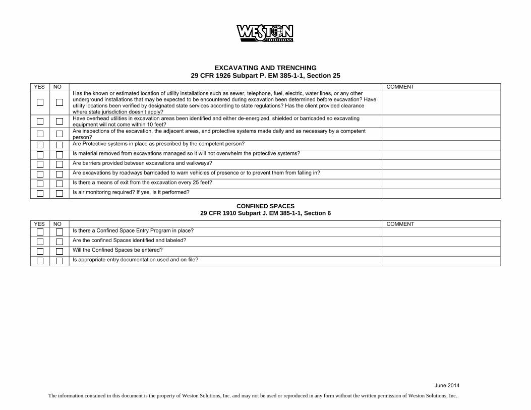
June 2014
The information contained in this document is the property of Weston Solutions, Inc. and may not be used or reproduced in any form without the written permission of Weston Solutions, Inc.
EXCAVATING AND TRENCHING 29 CFR 1926 Subpart P. EM 385-1-1, Section 25
YES NO COMMENT
Has the known or estimated location of utility installations such as sewer, telephone, fuel, electric, water lines, or any other underground installations that may be expected to be encountered during excavation been determined before excavation? Have utility locations been verified by designated state services according to state regulations? Has the client provided clearance where state jurisdiction doesn’t apply?
Have overhead utilities in excavation areas been identified and either de-energized, shielded or barricaded so excavating equipment will not come within 10 feet?
Are inspections of the excavation, the adjacent areas, and protective systems made daily and as necessary by a competent person?
Are Protective systems in place as prescribed by the competent person?
Is material removed from excavations managed so it will not overwhelm the protective systems?
Are barriers provided between excavations and walkways?
Are excavations by roadways barricaded to warn vehicles of presence or to prevent them from falling in?
Is there a means of exit from the excavation every 25 feet?
Is air monitoring required? If yes, Is it performed?
CONFINED SPACES 29 CFR 1910 Subpart J. EM 385-1-1, Section 6
YES NO COMMENT
Is there a Confined Space Entry Program in place?
Are the confined Spaces identified and labeled?
Will the Confined Spaces be entered?
Is appropriate entry documentation used and on-file?

June 2014
The information contained in this document is the property of Weston Solutions, Inc. and may not be used or reproduced in any form without the written permission of Weston Solutions, Inc.
ELECTRICAL 29 CFR 1926 Subpart K. EM 385-1-1, Section 11
YES NO COMMENT
Are electrical installations made according to the National Electrical Code and applicable local codes?
Qualified electricians make all connections and perform all work within 10 feet of live electric equipment.
Location of underground, overhead, under floor, behind wall electrical lines is known and communicated. Lines are documented by qualified person as de-energized where necessary.
Workers understand they must not work near live parts of electric circuits, unless they are qualified as required by OSHA or are protected by de-energizing and grounding the parts, guarding the parts by insulation, or other effective means?
Employees who regularly work on or around energized electrical equipment or lines are instructed in the cardiopulmonary resuscitation (CPR) methods.
Workers are prohibited from working alone on energized lines or equipment over 600 volts.
Are Ground-fault circuit interrupters (GFCI’s) or is ground fault circuit protection provided to protect employees from ground-fault hazards for all 115 – 120 Volt, 15 and 20 amp receptacle outlets which are not a part of the permanent wiring of a building or structure at construction sites?
Circuit breakers are labeled.
Circuit breaker and all cabinets with exposed electric conductors are kept tightly closed.
Unused openings (including conduit knockouts) in electrical enclosures and fittings are closed with appropriate covers, plugs, or plates.
Sufficient access and working space is provided and maintained about all electrical equipment to permit ready and safe operations and maintenance.
Motors are located within sight of their controllers or controller disconnecting means are capable of being locked in the pen position or is a separate disconnecting means installed in the circuit within sight of the motor.
Are visual inspections of extension cords and cord-and plug-connected equipment conducted daily? Is equipment found damaged or defective tagged and removed from service, and not used until repaired?
Wet Areas - Is portable lighting used in wet or conductive locations, such as tanks or boilers operated at no more than 12 volts and protected by GFCIs.
Are electrical installations in hazardous areas to NEC?
Metal ladders and tools including tape measures or fabric with metal thread are prohibited where contact with energized electrically parts is possible.
All extension cords are the three-wire type, designed and rated for hard or extra hard usage?
Worn or frayed electrical cords or cables are taken out of service. Fastening with staples, hanging from nails or suspending extension cords by wire is prohibited.
Electric wire/flexible cord passing through work areas is protected from damage such as foot traffic, vehicles, sharp corners, projections and pinching? Flexible cords and cables passing through holes are protected by bushings or fittings?
Before an employee or contractor performs any service or maintenance on a system where the unexpected energizing, start up, or release of kinetic or stored energy could occur and cause injury or damage, the system is to be isolated. Only authorized persons may apply and remove lockouts and tags.
Contractors planning to use hazardous energy control procedures submit their hazardous energy control plan to the WESTON site safety officer or designee before implementing lockout/tagout procedures.
There is a site specific hazardous energy control plan that clearly and specifically outlines the scope, purpose, authorization, rules and techniques to be used for the control of hazardous energy.
Workers possess the knowledge and skills required for the safe application, usage, and removal of energy controls.
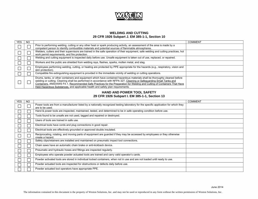
June 2014
The information contained in this document is the property of Weston Solutions, Inc. and may not be used or reproduced in any form without the written permission of Weston Solutions, Inc.
WELDING AND CUTTING 29 CFR 1926 Subpart J. EM 385-1-1, Section 10
YES NO COMMENT
Prior to performing welding, cutting or any other heat or spark producing activity, an assessment of the area is made by a competent person to identify combustible materials and potential sources of flammable atmospheres.
Welders, cutters and their supervisors are trained in the safe operation of their equipment, safe welding and cutting practices, hot work permit requirements, and fire protection.
Welding and cutting equipment is inspected daily before use. Unsafe equipment is taken out of use, replaced, or repaired.
Workers and the public are shielded from welding rays, flashes, sparks, molten metal, and slag.
Employees performing welding, cutting, or heating are protected by PPE appropriate for the hazards (e.g., respiratory, vision and skin protection).
Compatible fire extinguishing equipment is provided in the immediate vicinity of welding or cutting operations.
Drums, tanks, or other containers and equipment which have contained hazardous materials shall be thoroughly cleaned before welding or cutting. Cleaning shall be performed in accordance with NFPA 327, Cleaning or Safeguarding Small Tanks and Containers, ANSI/AWS F4.1, Recommended Safe Practices for the Preparation for Welding and Cutting of Containers That Have Held Hazardous Substances, and applicable health and safety plan requirements.
HAND AND POWER TOOL SAFETY 29 CFR 1926 Subpart I. EM 385-1-1, Section 13
YES NO COMMENT
Power tools are from a manufacturer listed by a nationally recognized testing laboratory for the specific application for which they are to be used.
Hand & power tools are inspected, maintained, tested, and determined to be in safe operating condition before use.
Tools found to be unsafe are not used, tagged and repaired or destroyed.
Users of tools are trained in safe use.
Electrical tools have cords and plug connections in good repair.
Electrical tools are effectively grounded or approved double insulated.
Reciprocating, rotating, and moving parts of equipment are guarded if they may be accessed by employees or they otherwise create a hazard.
Safety clips/retainers are installed and maintained on pneumatic impact tool connections.
Chain saws have an automatic chain brake or anti-kickback device.
Pneumatic and hydraulic hoses and fittings are inspected regularly.
Employees who operate powder actuated tools are trained and carry valid operator’s cards.
Powder activated tools are stored in individual locked containers, when not in use and are not loaded until ready to use.
Powder actuated tools are inspected for obstructions or defects daily before use.
Powder actuated tool operators have appropriate PPE.
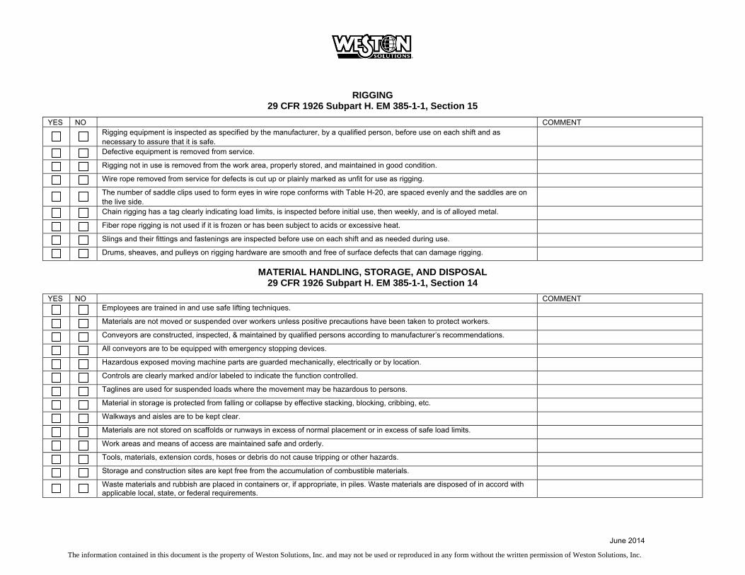
June 2014
The information contained in this document is the property of Weston Solutions, Inc. and may not be used or reproduced in any form without the written permission of Weston Solutions, Inc.
RIGGING 29 CFR 1926 Subpart H. EM 385-1-1, Section 15
YES NO COMMENT
Rigging equipment is inspected as specified by the manufacturer, by a qualified person, before use on each shift and as necessary to assure that it is safe.
Defective equipment is removed from service.
Rigging not in use is removed from the work area, properly stored, and maintained in good condition.
Wire rope removed from service for defects is cut up or plainly marked as unfit for use as rigging.
The number of saddle clips used to form eyes in wire rope conforms with Table H-20, are spaced evenly and the saddles are on the live side.
Chain rigging has a tag clearly indicating load limits, is inspected before initial use, then weekly, and is of alloyed metal.
Fiber rope rigging is not used if it is frozen or has been subject to acids or excessive heat.
Slings and their fittings and fastenings are inspected before use on each shift and as needed during use.
Drums, sheaves, and pulleys on rigging hardware are smooth and free of surface defects that can damage rigging.
MATERIAL HANDLING, STORAGE, AND DISPOSAL 29 CFR 1926 Subpart H. EM 385-1-1, Section 14
YES NO COMMENT
Employees are trained in and use safe lifting techniques.
Materials are not moved or suspended over workers unless positive precautions have been taken to protect workers.
Conveyors are constructed, inspected, & maintained by qualified persons according to manufacturer’s recommendations.
All conveyors are to be equipped with emergency stopping devices.
Hazardous exposed moving machine parts are guarded mechanically, electrically or by location.
Controls are clearly marked and/or labeled to indicate the function controlled.
Taglines are used for suspended loads where the movement may be hazardous to persons.
Material in storage is protected from falling or collapse by effective stacking, blocking, cribbing, etc.
Walkways and aisles are to be kept clear.
Materials are not stored on scaffolds or runways in excess of normal placement or in excess of safe load limits.
Work areas and means of access are maintained safe and orderly.
Tools, materials, extension cords, hoses or debris do not cause tripping or other hazards.
Storage and construction sites are kept free from the accumulation of combustible materials.
Waste materials and rubbish are placed in containers or, if appropriate, in piles. Waste materials are disposed of in accord with applicable local, state, or federal requirements.

June 2014
The information contained in this document is the property of Weston Solutions, Inc. and may not be used or reproduced in any form without the written permission of Weston Solutions, Inc.
FLOATING PLANT AND MARINE ACTIVITIES 29 CFR 1926 Subpart O. EM 385-1-1 Section 19
YES NO COMMENT
Floating plants that are regulated by the USCG have current inspections and certificates.
Before any floating plant is brought to the job site and placed in service it is inspected and determined to be in safe operating condition
Periodic inspections are made such that safe operating conditions are maintained. Strict compliance with EM 385-1-1, Section 19 is expected.
Plans are in place for removing or securing the plant and evacuation of personnel endangered by severe weather and other marine emergencies such as; fire, flooding, man overboard, hazardous materials incidents, etc.
Means of access are properly secured, guarded, and maintained free of slipping and tripping hazards.
Dredging operations follow guidelines as established in EM 385-1-1, Section 19.D.
PRESSURIZED EQUIPMENT AND SYSTEMS 29 CFR 1926 Subparts I, F. EM 385-1-1, Section 20
YES NO COMMENT
Pressurized equipment and systems are inspected before being placed into service.
Pressurized equipment or systems found to be unsafe are tagged “Out of Service-Do Not Use”.
Systems and equipment are operated, inspected, and maintained by qualified, designated personnel.
Safe clearance, lockout/tagout procedures are followed as appropriate during maintenance or repair.
Air hose, pipes, fittings are pressure-rated for the activity. Defective hoses are removed from service.
Hoses aren’t laid over ladders, steps, scaffolds, or walkways in a manner that creates a tripping hazard.
The use of compressed air for personal cleaning is prohibited. The use of compressed air for other cleaning is restricted to less than 30 psig.
Compressed gas cylinders are stored in well-ventilated locations.
Cylinders in storage are separated from flammable or combustible liquids and from easily ignitable materials by at least 40 feet or by a minimum five feet tall, ½ -hour fire resistive partition.
Stored cylinders containing oxidizing gases are separated from fuel gas cylinders by at least 20 feet or by a minimum five feet tall, ½ -hour fire resistive partition.
Cylinder valve caps are in place when cylinders are in storage, in transit, or a regulator is not in place.
Compressed gas cylinders in service are secured in substantial fixed or portable racks or hand trucks.
Oxygen cylinders and fittings are kept away from, and free from oil and grease.
Cylinder Storage areas are posted with the names of the gases in storage and with signs indicating "No Smoking or Open Flame".
Cylinders are to be stored such that mechanical and corrosion damage is avoided. Cylinders are not to be stored in areas required as an egress path.
Cylinders may be stored in the open outdoors, however, they must be protected from the ground to prevent corrosion and must be protected from temperatures that may exceed 125 degrees F.

June 2014
The information contained in this document is the property of Weston Solutions, Inc. and may not be used or reproduced in any form without the written permission of Weston Solutions, Inc.
WORK PLATFORMS/SCAFFOLDS 29 CFR 1926 Subparts L, M, N. EM 385-1-1 Sections 21, 22
YES NO COMMENT
Work platforms are erected, used, inspected, tested, maintained and repaired according to manufacturer’s requirements.
Construction, inspection, and disassembly of scaffolds is under the direction of a competent person.
Workers on scaffolding have been trained by a qualified person.
Scaffolds are erected on a firm and level surface and are square and plumb.
Scaffolds are not loaded in excess of rated capacity.
Working levels of work platforms are fully planked or decked.
Planks are in good condition and free from obvious defects.
Fabricated frame scaffolding four times higher than the base width is secured to building/structure according to manufacturer’s instruction and/or OSHA requirements.
Working platforms of scaffolding over ten feet in height have guard rails meeting OSHA specifications. Fall protection is suggested at four feet or greater.
Scaffolding/work platforms are accessed by means of a properly secured ladder or equivalent. Built on ladders conform to scaffold ladder requirements. Climbing of braces is not allowed.
Crane supported work platforms are designed and used in accordance with OSHA standards.
Elevating work platforms are operated, inspected, and maintained according to the equipment operations manual.
Employees working in aerial lifts remain firmly on the floor of the basket. Employees use fall protection while in an aerial lift basket.

June 2014
The information contained in this document is the property of Weston Solutions, Inc. and may not be used or reproduced in any form without the written permission of Weston Solutions, Inc.
WALKING AND WORKING SURFACES AND STAIRS 29 CFR 1926 Subparts L, M, X. EM 385-1-1, Sections 21, 22, 24
YES NO COMMENT
Work areas are clean, sanitary, and orderly
Work surfaces are kept dry or appropriate means are taken to assure the surfaces are slip-resistant
Accumulations of combustible dust are routinely removed.
Aisles and passageways are kept clear and marked as appropriate.
There is safe clearance for walking in aisles where motorized or mechanical handling equipment is operating.
Materials or equipment is stored in such a way that sharp projections will not interfere with the walkway.
Changes of direction or elevation are readily identifiable.
Aisles or walkways that pass near moving or operating machinery, welding operations or similar operations are arranged so employees will not be subjected to potential hazards.
Standard guardrails are provided wherever aisle or walkway surfaces are elevated more than 30 inches above any adjacent floor or the ground and bridges provided where workers must cross over conveyors and similar hazards.
There are standard stair rails or handrails on all stairways having four or more risers or with an elevation of 30 or more inches.
Stairways are at least 22 inches wide. (General Industry Standard)
Stairs angle no more than 50 and no less than 30 degrees, risers are uniform from top to bottom (plus or minus 1/4 inch) and are provided with a surface that renders them slip resistant.
Stairway handrails are not less than 36 inches above the leading edge of stair treads and have at least 3 inches of clearance between the handrails and the wall or surface they are mounted on.
Where doors or gates open directly on a stairway, there is a platform provided so the swing of the door does not reduce the width of the platform to less than 20 inches.
Where stairs or stairways exit directly into any area where vehicles may be operated, there are adequate barriers and warnings provided to prevent employees stepping into the path of traffic.
Signs are posted showing the load capacity of elevated storage areas.
An appropriate means of access and egress is provided for surfaces with 19 or more inches of elevation change.
Material on elevated surfaces is minimized, with that necessary for immediate work requirements piled, stacked, or racked in a manner to prevent it from tipping, falling, collapsing, rolling, or spreading.
FLOOR AND WALL HOLES AND OPENINGS 29 CFR 1926 Subpart M. EM 385-1-1, Section 24
YES NO COMMENT
Floor and roof openings that persons can walk into or fall through are guarded by a physical barrier or covered.
Holes (defined as equal to or greater than 2 inches in least dimension) where person could trip must be covered/protected.
Unprotected sides and edges on a walking/working surface six feet or more (note four feet in General Industry) are protected by guardrail system, safety net, or Personal Fall Arrest System (PFAS).
Unused portions of service pits and pits not actually in use are either covered or protected by guardrails or equivalent.
Coverings for holes or other openings must be constructed of sufficient strength to support any anticipated load, must be secured in place to prevent accidental removal or displacement, and must be marked indicating purpose (e.g., stenciled "Hole" or painted contrasting color to surroundings).
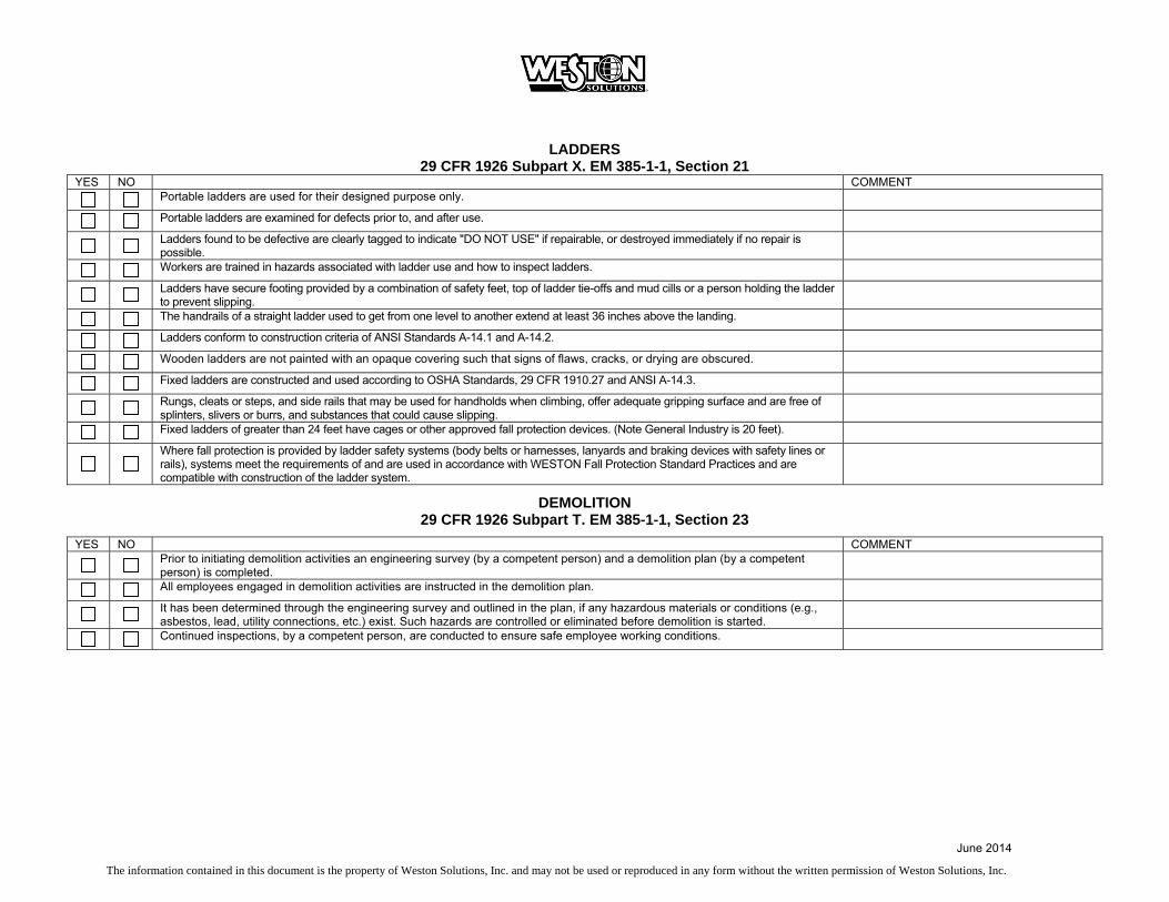
June 2014
The information contained in this document is the property of Weston Solutions, Inc. and may not be used or reproduced in any form without the written permission of Weston Solutions, Inc.
LADDERS 29 CFR 1926 Subpart X. EM 385-1-1, Section 21
YES NO COMMENT
Portable ladders are used for their designed purpose only.
Portable ladders are examined for defects prior to, and after use.
Ladders found to be defective are clearly tagged to indicate "DO NOT USE" if repairable, or destroyed immediately if no repair is possible.
Workers are trained in hazards associated with ladder use and how to inspect ladders.
Ladders have secure footing provided by a combination of safety feet, top of ladder tie-offs and mud cills or a person holding the ladder to prevent slipping.
The handrails of a straight ladder used to get from one level to another extend at least 36 inches above the landing.
Ladders conform to construction criteria of ANSI Standards A-14.1 and A-14.2.
Wooden ladders are not painted with an opaque covering such that signs of flaws, cracks, or drying are obscured.
Fixed ladders are constructed and used according to OSHA Standards, 29 CFR 1910.27 and ANSI A-14.3.
Rungs, cleats or steps, and side rails that may be used for handholds when climbing, offer adequate gripping surface and are free of splinters, slivers or burrs, and substances that could cause slipping.
Fixed ladders of greater than 24 feet have cages or other approved fall protection devices. (Note General Industry is 20 feet).
Where fall protection is provided by ladder safety systems (body belts or harnesses, lanyards and braking devices with safety lines or rails), systems meet the requirements of and are used in accordance with WESTON Fall Protection Standard Practices and are compatible with construction of the ladder system.
DEMOLITION 29 CFR 1926 Subpart T. EM 385-1-1, Section 23
YES NO COMMENT
Prior to initiating demolition activities an engineering survey (by a competent person) and a demolition plan (by a competent person) is completed.
All employees engaged in demolition activities are instructed in the demolition plan.
It has been determined through the engineering survey and outlined in the plan, if any hazardous materials or conditions (e.g., asbestos, lead, utility connections, etc.) exist. Such hazards are controlled or eliminated before demolition is started.
Continued inspections, by a competent person, are conducted to ensure safe employee working conditions.

June 2014
The information contained in this document is the property of Weston Solutions, Inc. and may not be used or reproduced in any form without the written permission of Weston Solutions, Inc.
TREE MAINTENANCE AND REMOVAL 29 CFR 1910 Subpart R. EM 385-1-1, Section 31
YES NO COMMENT
Tree maintenance or removal is done is under the direction of a qualified person.
Tree work, in the vicinity of charged electric lines, is by trained persons qualified to work with electricity and tree work. Appropriate distances are maintained for all workers who are not qualified.
Equipment is inspected, maintained, repaired, and used in accordance with the manufacturer’s directions.
Prior to felling actions are planned to include clearing of the area to permit safe working conditions and escape.
Employees must be trained in the safe operation of all equipment.
All equipment and machinery is inspected and determined safe prior to use.
Work is performed under requirements of FLD 43.
BLASTING 29 CFR 1926 Subpart U. EM 385-1-1, Section 29
YES NO COMMENT
A blasting safety plan is developed prior to bringing explosives on-site.
The transportation, handling, storage, and use of explosives, blasting agents, and blasting equipment must be directed and supervised by a person with proven experience and ability in blasting operations. Licensing of person is verified.
Blasting operations in or adjacent to cofferdams, piers, underwater structures, buildings, structures, or other facilities must be carefully planned with full consideration to potential vibration and damage.
HAZARDOUS, TOXIC, AND RADIOACTIVE WASTE AND UNDERGROUND STORAGE TANK (UST) ACTIVITIES 29 CFR 1926 Subpart D. EM 385-1-1, Section 28
YES NO COMMENT
All construction activities performed with known or potential exposure to hazardous waste are conducted in accordance with Hazardous Waste Operations and Emergency Response requirements.

June 2014
The information contained in this document is the property of Weston Solutions, Inc. and may not be used or reproduced in any form without the written permission of Weston Solutions, Inc.
CONCRETE and MASONRY CONSTRUCTION 29 CFR 1926 Subpart Q. EM 385-1-1, Section 27
YES NO COMMENT
Construction loads are not placed on a concrete or masonry structure or portion of a concrete or masonry structure unless the employer determines, based on information from a person who is qualified in structural design, that the structure or portion of the structure is capable of supporting the loads.
Employees are not permitted to work above or in positions exposed to protruding reinforcing steel or other impalement hazards unless provisions have been made to control the hazard.
Sections of concrete conveyances and airlines under pressure are secured with wire rope (or equivalent material) in addition to the regular couplings or connections.
Structural and reinforcing steel for walls, piers, columns, and similar vertical structures is supported and/or guyed to prevent overturning or collapse
All form-work, shoring, and bracing is designed, fabricated, erected, supported, braced, and maintained so it will safely support all vertical and lateral loads that may be applied until the loads can be supported by the structure.
Shoring equipment is inspected prior to erection to determine that it is specified in the shoring design. Any equipment found to be damaged is not used.
Erected shoring equipment is inspected immediately prior to, during, and immediately after the placement of concrete. Any shoring equipment that is found to be damaged, displaced, or weakened is immediately reinforced or re-shored.
Shoring, vertical slip forms and jacks conform with requirements of Section 27.B.08-13 of USACE EM 385-1-1.
Forms and shores (except those on slab or grade and slip forms) are not removed until the individual responsible for forming and/or shoring determines that the concrete has gained sufficient strength to support its weight and all superimposed loads.
Precast concrete members are adequately supported to prevent overturning or collapse until permanent connections are complete
No one is permitted under pre-cast concrete members being lifted or tilted into position except employees required for the erection of those members.
Lift slab operations are planned and designed by a registered engineer or architect.
Hydraulic jacks used in lift slab construction have a safety device that causes the jacks to support the load in any position if the jack malfunctions
No one is permitted under the slab during jacking operations.
A limited access zone is established whenever a masonry wall is being constructed.
Fall protection is provided to masonry workers exposed to falls of 6 feet or more.

June 2014
The information contained in this document is the property of Weston Solutions, Inc. and may not be used or reproduced in any form without the written permission of Weston Solutions, Inc.
STEEL ERECTION 29 CFR 1926 Subpart R. EM 385-1-1, Section 27
YES NO COMMENT
Impact wrenches have a locking device for retaining the socket. Containers shall be provided for storing or carrying rivets, bolts, and drift pins, and secured against accidental displacement when aloft.
Structural and reinforcing steel for walls, piers, columns, and similar vertical structures shall be guyed and supported to prevent collapse
No loading is placed upon steel joists until all bridging is completely and permanently installed.
Workers are provided fall protection whenever they are exposed to falls of 1.8 m (6 ft) or more (EM 385-1-1).
Temporary flooring in skeleton steel erection conforms with Section 27.F of USACE 385-1-1
ROOFING 29 CFR 1926 Subpart M. EM 385-1-1, Sections 21, 22, 24, 27
Yes No COMMENT In the construction, maintenance, repair, and demolition, of roofs, fall protection systems is provided that will prevent personnel
from slipping and failing from the roof and prevent personnel on lower levels from being struck by falling objects
On all roofs greater than 4.8 m (16 ft) in height, a hoisting device, stairways, or progressive platforms are furnished for supplying materials and equipment.
Roofing materials and accessories that could be moved by the wind, including metal roofing panels, that are on the roof and unattached are secured when wind speeds are greater than, or are anticipated to exceed, 10 mph.
Level, guarded platforms are provided at the landing area on the roof.
When their use is permitted, warning line systems comply with USACE Section 27.07 of EM 385-1-1.
Workers involved in roof-edge materials handling or working in a storage area located on a roof with a slope -/= to four vertical to twelve horizontal and with edges 6 ft or more above lower levels are protected by the use of a guardrail, safety net, or personal fall arrest system along all unprotected roof sides and edges of the area.

June 2014
The information contained in this document is the property of Weston Solutions, Inc. and may not be used or reproduced in any form without the written permission of Weston Solutions, Inc.
ENVIRONMENTAL COMPLIANCE Yes No Comments
Environmental Compliance and Waste Management Plan on file.
Waste Determination Made.
Manifest and/or Shipping Papers prepared and filed.
Manifest Exception Reports Prepared, as necessary. Procedures to track manifests in place.
State Annual and EPA Biennial Reporting Information Available.
RCRA Personnel Training Records on file.
CAA Permits on file.
CWA Permits on file.
RCRA Permits on file.
State and/or Local Permits on file.
RCRA Inspections conducted and Documentation on file.
Transporter and TSD compliance information on file.
Waste Accumulation Areas Managed Properly.
Wetlands Areas Identified and Protected.
Endangered, Threatened, or Special Concern Species or Areas Identified and Protective Methods Determined.
Run-on and Runoff Concerns Identified and Managed.
Adjacent Land Areas Protected as Necessary.
Non-Hazardous Solid Wastes Managed Properly.
June 2014
The information contained in this document is the property of Weston Solutions, Inc. and may not be used or reproduced in any form without the written permission of Weston Solutions, Inc.
MISCELLANEOUS REGULATORY and POLICY COMPLIANCE Yes No Comments
Personnel Training Records for DOT Materials Handling on file.
Noise Control Issues Addressed and Managed.
Site Security Issues Identified and Managed.
Known Historical, Archeological, and Cultural Resources Identified and Managed.
WESTON EHS Analysis Checklist In Use.
Safety Observation and Recognition Program in place.
Weekly EHS Report Card System in place.
Federal, State, and Local Required Postings in place.
Site specific Lockout/Tagout Program is in place.
Site-specific Confined Space Program is in place.
Site Safety Officer filing system is in place and up to date.
APPENDIX B
COMMUNITY AIR MONITORING PLAN (CAMP)

Community Air Monitoring Plan
Study Area Bounded by Pyrex Street, E. Pulteney Street, Post Creek and Chemung River
Corning, NY NYSDEC Project IS 851046
June 2014
Prepared for
Corning Incorporated Corning, New York
Prepared by
WESTON SOLUTIONS, INC. West Chester, Pennsylvania 19380
W.O. No. 02005.056.001.0001
2014_CNY_SCWP_APP_B_CAMP_FINAL.docx 6/20/2014
ii
TABLE OF CONTENTS
Section Page 1. INTRODUCTION..............................................................................................................1
2. METHODS .........................................................................................................................1
3. CALIBRATIONS ...............................................................................................................24. DATA RECORDING ........................................................................................................3
5. ACTION LEVELS .............................................................................................................3

2014_CNY_SCWP_APP_B_CAMP_FINAL.DOCX 6/20/2014
iii
LIST OF ACRONYMS
CAMP Community Air Monitoring Plan
COPCs constituents of potential concern
HASP Health and Safety Plan
mg/m3 milligrams per cubic meter
μg/m3 micrograms per cubic meter
NYSDEC New York State Department of Environmental Conservation
WESTON® Weston Solutions, Inc.

2014_CNY_SCWP_APP_B_CAMP_FINAL.docx 6/20/2014
1
1. INTRODUCTION
This Community Air Monitoring Plan (CAMP) has been prepared by Weston Solutions, Inc.
(WESTON®) on behalf of Corning Incorporated to detail the dust control and air monitoring
procedures to be performed during the execution of characterization activities at the Study Area
located in Corning, New York, bounded by Pyrex Street on the west, E. Pulteney Street on the
north, Post Creek on the east and the Chemung River on the south (Study Area). This air
monitoring plan will supplement the existing Health and Safety Plan (HASP) and provide an
additional measure of protection to potential receptors not directly involved with the
characterization activities.
As presented in the Study Area Characterization Work Plan (Work Plan), intrusive
characterization activities planned to be conducted within the Study Area may include subsurface
soil sampling and groundwater investigations. Since the primary constituents of potential
concern (COPCs) at the Study Area are arsenic, cadmium, and lead, air monitoring for dust
particulates and dust control techniques will be performed during intrusive activities to provide
an additional measure of protection to the surrounding community.
2. METHODS
Perimeter air monitoring for dust particles will be conducted at a minimum of two stations, one
generally located upwind, and one generally located downwind of any intrusive characterization
activity. In addition, due to the close proximity of playgrounds, athletic playing fields, schools
and childcare centers, more stringent CAMP requirements will be necessary. When work areas
are within 20 feet of these locations, the continuous monitoring locations for particulates must
reflect the nearest potentially exposed individuals. The use of engineering controls such as dust
barriers will be considered to prevent exposures related to the work activities and to control dust
and odors. Consideration will be given to implementing the planned activities when potentially
exposed populations are at a minimum (i.e. during hours when children are not likely to be
present). Common-sense measures to keep dust and odors at a minimum around the work areas
2014_CNY_SCWP_APP_B_CAMP_FINAL.docx 6/20/2014
2
will also be implemented to ensure that the children are protected at all times. No visible dust
will leave the work area.
As the location of characterization activities will change, the location of the monitoring point
relative to the activity will be modified as needed and documented. The monitoring location will
be positioned to provide data representative of potential migration of dust in the direction of
nearby receptors. The perimeter monitoring equipment will be portable, which will allow the
monitoring network to be adjusted if needed to adapt to changes in activities or meteorological
conditions.
Particulate monitoring is the measurement of fine liquid or solid particles such as dust, smoke,
mist, fumes or smog, in particle sizes less than 10 microns (PM10), in the ambient air. During
intrusive activities such as subsurface soil sampling and groundwater monitoring well
installation, the generation of dust particles will be monitored. The equipment selected to
monitor PM10 will be the Thermo Electron Corporation personal DataRAM (pDR), or equivalent.
The pDR is a light-scattering monitor, designed for measuring airborne particulates such as
aerosols and dusts. The units are portable and measure the concentration of airborne particulate
matter (up to 10 m in size) continuously and in real time, with results expressed in milligrams
per cubic meter (mg/m3), or 1,000 micrograms per cubic meter (μg/m3). Particulate
concentrations can be measured over the following ranges: 0.01 – 10 mg/m3 (equivalent to 10 –
10,000 μg/m3) and 0.1 – 100 mg/m3 (equivalent to 100 – 100,000 μg/m3). The pDR meets
performance standard for a real-time particulate monitor according to the New York State
Department of Environmental Conservation (NYSDEC) Technical Guidance for Site
Investigation and Remediation; May 2010.
3. CALIBRATIONS
Calibration of instruments will be performed prior to the start of daily activities. Additional
calibrations will be performed as needed or whenever maintenance is performed involving the
functional elements of the unit. Calibration data will be documented in the field log book or on
designated calibration log sheets.

2014_CNY_SCWP_APP_B_CAMP_FINAL.docx 6/20/2014
3
4. DATA RECORDING
The data collected during the monitoring program will be used for real-time data display and
notification to on-site personnel when the action levels are exceeded (action levels are discussed
in Section 5). All ambient air monitoring data will be recorded in the site field logbook or
designated field sheets and the results of the air monitoring will be communicated to the
NYSDEC and NYSDOH on scheduled basis (i.e. daily for levels which require actions, weekly
for routine monitoring data).
5. ACTION LEVELS
The action level established herein will be used as an indicator that potential excessive migration
of dust particles may be occurring during the characterization activities. Monitored ambient air
concentrations above the action level will result in actions being taken to more stringently
control fugitive emissions or trigger quantitative sampling.
The NYSDEC recommended action level for fugitive dust is 100 μg/m3 greater than background
(measured at the upwind location) for a 15 minute period. At this concentration, work may
continue with dust suppression techniques provided that no visible dust is migrating from the
working area, and the downwind particulate levels do not exceed 150 μg/m3 greater than
background (measured at the upwind location). If the downwind particulate levels exceed 150
μg/m3 greater than background (measured at the upwind location), work will stop and dust
suppression techniques will be re-evaluated.
If the perimeter monitors detect concentrations above the 100 μg/m3 action level, Site
supervisory personnel will be notified. Notifications will be sent to the WESTON Site Manager
and the Site Health and Safety Officer. Upon receiving the notification message, the supervisor
will assess the situation and initiate appropriate administrative and/or engineering controls to
mitigate the migration of dust particles.

APPENDIX C
QUALITY ASSURANCE PROJECT PLAN (QAPP)
Quality Assurance Project Plan
Study Area Bounded by Pyrex Street, E. Pulteney Street, Post Creek and Chemung River
Corning, NY NYSDEC Project ID 851046
June 2014
Prepared for
Corning Incorporated Corning, New York
Prepared by
WESTON SOLUTIONS, INC. West Chester, Pennsylvania 19380
W.O. No. 02005.056.001.

2014_CNY_SCWP_APP_C_QAPP_FINAL.docx 6/20/2014
i
TABLE OF CONTENTS
Section Page
1. INTRODUCTION.......................................................................................................... 1-11.1 PROJECT SCOPE AND GOALS ....................................................................... 1-11.2 PROJECT DATA QUALITY AND OBJECTIVES............................................ 1-21.3 DATA QUALITY OBJECTIVES ....................................................................... 1-21.4 PROJECT SCHEDULE ....................................................................................... 1-4
2. PROJECT ORGANIZATION AND RESPONSIBILITIES ..................................... 2-12.1 CORNING INCORPORATED COMPANY PERSONNEL .............................. 2-22.2 WESTON PERSONNEL ..................................................................................... 2-2
2.2.1 Project Manager .................................................................................... 2-22.2.2 Technical Advisors/Quality Assurance Coordinator ............................ 2-32.2.3 Field Team Site Manager/Health and Safety Officer ........................... 2-32.2.4 Data Manager ........................................................................................ 2-4
2.3 LABORATORY STAFFING .............................................................................. 2-42.3.1 Laboratory Personnel and Responsibilities ........................................... 2-52.3.2 Subcontractors ....................................................................................... 2-6
2.4 TRAINING AND CERTIFICATION ................................................................. 2-62.4.1 Field Staff Training and Certification ................................................... 2-6
3. FIELD SAMPLING PROCEDURES .......................................................................... 3-13.1 PRE-SAMPLING PROCEDURES ..................................................................... 3-13.2 DRILLING PROCEDURES ................................................................................ 3-13.3 SUBSURFACE SOIL SAMPLING PROCEDURES ......................................... 3-23.4 GROUNDWATER SAMPLING PROCEDURES .............................................. 3-33.5 FIELD QUALITY CONTROL SAMPLES......................................................... 3-3
3.5.1 Equipment Rinsate Blanks .................................................................... 3-43.5.2 Trip Blanks............................................................................................ 3-43.5.3 Field Duplicate Samples ....................................................................... 3-43.5.4 Matrix Spike/Matrix Spike Duplicates (MS/MSDs) ............................. 3-5
3.6 SAMPLE HANDLING ........................................................................................ 3-53.6.1 Sample Custody .................................................................................... 3-63.6.2 Sample Identification ............................................................................ 3-73.6.3 Sample Labels ....................................................................................... 3-83.6.4 Shipping Procedures ............................................................................. 3-8
3.7 LABORATORY OPERATIONS ........................................................................ 3-83.7.1 Sample Receipt ..................................................................................... 3-93.7.2 Sample Storage ..................................................................................... 3-9

2014_CNY_SCWP_APP_C_QAPP_FINAL.docx 6/20/2014
ii
TABLE OF CONTENTS (CONTINUED)
3.7.3 Sample Tracking ................................................................................... 3-93.7.4 Recordkeeping .................................................................................... 3-10
4. FIELD OPERATIONS .................................................................................................. 4-14.1 FIELD RECORDS ............................................................................................... 4-1
4.1.1 Field Logbooks ..................................................................................... 4-14.1.2 Soil Sampling and Borehole Log Forms ............................................... 4-34.1.3 Corrections to Documentation .............................................................. 4-3
4.2 SITE SURVEYING ............................................................................................. 4-34.3 ANNOTATION OF MAPS ................................................................................. 4-34.4 AIR MONITORING ............................................................................................ 4-44.5 FIELD CALIBRATION ...................................................................................... 4-4
5. LABORATORY ANALYSIS ........................................................................................ 5-15.1 LABORATORY REQUIREMENTS .................................................................. 5-15.2 METHOD DETECTION LIMITS ....................................................................... 5-15.3 ANALYTICAL METHODS AND HOLDING TIMES ...................................... 5-25.4 QUALITY CONTROL AND QUALITY ASSURANCE ................................... 5-25.5 DATA REPORTING ........................................................................................... 5-35.6 DATA REVIEW/VALIDATION ........................................................................ 5-3
6. REFERENCES ............................................................................................................... 6-1
2014_CNY_SCWP_APP_C_QAPP_FINAL.docx 6/20/2014
iii
LIST OF TABLES
Table 3-1 Sample Summary Table ..................................................................................... 3-11
Table 3-2 Analytical Methodologies .................................................................................. 3-12
Table 3-3 Field Sample Identifiers ..................................................................................... 3-13
Table 5-1 Reporting Limits and Method Detection Limits .................................................. 5-5

2014_CNY_SCWP_APP_C_QAPP_FINAL.docx 6/20/2014
iv
LIST OF FIGURES
Figure 3-1 Standard TestAmerica Chain of Custody Form ................................................. 3-14
2014_CNY_SCWP_APP_C_QAPP_FINAL.docx 6/20/2014
v
APPENDICES
ATTACHMENT A TestAmerica Quality Assurance Manual and Standard Operating Procedures

2014_CNY_SCWP_APP_C_QAPP_FINAL.docx 6/20/2014
vi
LIST OF ACRONYMS
ASP Analytical Services Protocol
ASTM American Society of Testing and Materials
BS blank spike
BSD blank spike duplicate
CAMP Community Health and Safety Plan
cfs cubic feet per second
COPC constituents of potential concern
CPR cardiopulmonary resuscitation
DQO data quality objectives
DUSR data usability summary report
EDD electronic data deliverable
ELAP Environmental Laboratory Approval Program
GPR ground penetrating radar
HASP Health and Safety Plan
ID sample identification
LCS laboratory control sample
MCAWW Methods for Chemical Analyses of Waters and Wastes
MDL method detection limits
MS matrix spike
MSD matrix spike duplicate
ND non detect
NYSDEC New York State Department of Environmental Conservation
OSHA Occupational Safety and Health Administrations
PID Photoionization Detector
PPE personal protective equipment
QA quality assurance
QAM TestAmerica Quality Assurance Manual
QAO quality assurance objectives
QAPP Quality Assurance Project Plan
QC quality control
2014_CNY_SCWP_APP_C_QAPP_FINAL.docx 6/20/2014
vii
LIST OF ACRONYMS (CONTINUED)
RPD relative percent difference
SCO site cleanup objectives
SOP standard operating procedure
SOW scope of work
USEPA U.S. Environmental Protection Agency
WESTON® Weston Solutions, Inc.

2014_CNY_SCWP_APP_C_QAPP_FINAL.docx 6/20/2014 1-1
1. INTRODUCTION
This Quality Assurance Project Plan (QAPP) has been prepared by Weston Solutions, Inc.
(WESTON®) on behalf of Corning Incorporated to detail the quality assurance/quality control
(QA/QC) procedures for conducting field activities at the Study Area bounded by Pyrex Street
on the west, E. Pulteney Street on the north, Post Creek on the east and the Chemung River on
the south (Study Area) in Corning, New York.
1.1 PROJECT SCOPE AND GOALS
The purpose of the characterization activities detailed in the Study Area Characterization Work
Plan (Work Plan) is to assess the potential presence and nature of fill material within the Study
Area. Accordingly, Corning Incorporated is conducting a historic records search and review to
establish a history of the Study Area and identify areas where fill material may potentially have
been placed. This records search includes a review of historic aerial photographs to identify areas
where historic disturbances may have occurred. The Work Plan includes a summary of the
historic records review and a plan for characterization activities based on the preliminary results
of the historic records review. The characterization activities described in the Work Plan are
designed to assess whether potential fill material is present within the Study Area and to develop
data necessary for understanding the current conditions within the Study Area and associated
potential exposure pathways.
The specific objectives of the Work Plan are as follows:
1. In areas where historic records indicate potential disturbances:
a. assess the nature and extent of the potential disturbance area, and
b. assess potential exposure pathways, in the event fill material is found.
2. In areas where historic records do not indicate potential disturbances, evaluate the
potential presence of fill material.

2014_CNY_SCWP_APP_C_QAPP_FINAL.docx 6/20/2014 1-2
Additional details, including figures of proposed sampling locations are included in the Work
Plan.
1.2 PROJECT DATA QUALITY AND OBJECTIVES
This QAPP documents the QA/QC measures that will be followed during the implementation of
Work Plan activities and any follow-up activities that may be conducted (if required). The
objective of the data collection is to support the characterization activities within the Study Area.
The QAPP provides a description of the analytical, field and reporting procedures that may be
used by WESTON and its subcontractors within the Study Area for the following activities:
Soil boring installation;
Soil sampling;
Well installation;
Monitoring well sampling;
Well abandonment;
Laboratory analysis; and
Report preparation.
The purpose of the QA/QC program is to produce analytical measurement data of known quality
that satisfy the project data quality objectives (DQOs). DQOs are data quality planning and
evaluation tools for sampling and analysis activities. A consistent and comprehensive approach
for developing and using these tools is necessary to ensure that enough data are produced and are
of sufficient quantity to make decisions for the project. The DQO process is described in the
subsequent subsection.
1.3 DATA QUALITY OBJECTIVES
The DQO process and quality assurance objectives for program planning are presented in this
section. The procedures of the overall QA/QC have been developed to ensure that the analytical

2014_CNY_SCWP_APP_C_QAPP_FINAL.docx 6/20/2014 1-3
data collected through implementation of the Work Plan are of known and acceptable level of
quality.
Primary DQOs will include the following:
Complete the Study Area characterization activities to adequately confirm the presence/absence of fill materials;
Complete the Study Area characterization activities to adequately confirm the presence/absence of constituents at concentrations greater than reasonable quantitation limits; and
Provided additional information to fully characterize potential migration pathways.
To achieve the DQOs, QA measures will be implemented throughout the project to ensure that
the data meet known and suitable data quality criteria such as selectivity, precision,
accuracy/bias, representativeness, comparability and completeness. The sampling data will be
quality-controlled through the collection of field QC samples and the calibration of field and
laboratory equipment. In addition, replicate samples will be collected and submitted as part of
the QA program. Implementation of QA/QC measures to achieve the DQOs will limit the chance
of generating inadequate or incomplete data.
The DQOs will be accomplished by ensuring that the following analytical objectives are met.
These analytical objectives will be the following:
To prepare and analyze samples using standard methods; and
To obtain usable and defensible analytical results.
Quality assurance objectives (QAOs) are the detailed QC specification for selectivity, precision,
accuracy, representativeness, comparability, and completeness. In regards to measurements of
data quality, the QA/QC program will include the following QAOs:
Provide a mechanism for the ongoing control and evaluation of measurement data quality; and
2014_CNY_SCWP_APP_C_QAPP_FINAL.docx 6/20/2014 1-4
Provide measures of data quality in terms of selectivity, precision, accuracy, completeness, representativeness, and comparability to assess whether the data meet the project objectives and can be used for their intended purpose.
The primary application of the analytical results will be to generate sufficient information to
determine the presence or absence of Constituents of Potential Concern (COPCs) within the
Study Area’s media and to determine the presence/absence of and/or the nature and extent of
COPCs at the Study Area. The project data manager will track data from collection of samples
through login at the laboratory to delivery by technical report and electronic data delivery,
oversee necessary validation/data usability summary report preparation (DUSR), and coordinate
laboratory corrective actions.
The following sections discuss the steps to be taken to ensure the quality of data acquired during
the work. The representativeness of the measurement data is a function of the sampling strategy
and will be achieved by following the procedures in the Work Plan. The quality of the analytical
results is a function of the analytical system and will be achieved by using standard methods and
the QC practices discussed in this section. The basis for assessing selectivity, precision,
accuracy, representativeness, comparability, and completeness is discussed in the TestAmerica’s
QA Manual (QAM) found in Attachment A.
1.4 PROJECT SCHEDULE
The schedule for project activities is presented in Section 5.1 of the Work Plan.

2014_CNY_SCWP_APP_C_QAPP_FINAL.docx 6/20/2014 2-1
2. PROJECT ORGANIZATION AND RESPONSIBILITIES
A general description of the organization and the responsibilities of key individuals for the
project teams are provided in this section. This QAPP covers the work of Corning Incorporated,
WESTON, and subcontractors. Responsibilities and authority may vary among subcontractors.
The following sections give brief descriptions of the primary staff and the responsibilities of the
management, QA/QC, and primary task leadership for the field and laboratory tasks. Project
activities will be performed within the framework of the organization and functions described in
this section.
The organization for the project is designed to provide clear lines of responsibility and authority.
This control structure provides for the following:
Identifying lines of communication and coordination;
Monitoring project schedules and performance;
Managing key technical resources;
Coordinating support functions such as laboratory analysis and data management; and
Rectifying deficiencies.
QA personnel will have sufficient authority, organizational freedom, and ability to act as
follows:
Identify QA problems.
Initiate, recommend, or provide solutions to QA problems through designated channels.
Ensure that program activities, including processing information deliverables, and installation or use of equipment, are reviewed in accordance with QA objectives.
Ensure that deficiencies/non-conformances are corrected.
Ensure that further processing, delivery, or use of data is controlled until the proper disposition of a nonconformance, deficiency, or unsatisfactory condition has occurred.

2014_CNY_SCWP_APP_C_QAPP_FINAL.docx 6/20/2014 2-2
The organizational structure will be reviewed and updated periodically by a WESTON Project
Manager. Any necessary staff changes will be filled with qualified personnel and communicated
to the Corning Incorporated Project Manager.
2.1 CORNING INCORPORATED COMPANY PERSONNEL
Mr. Michael Ford, will serve as the Corning Incorporated Project Manager for the Study Area.
Mr. Ford is responsible for primary contact with New York State Department of Environmental
Control (NYSDEC) and for oversight of the project. Mr. Ford’s responsibilities include defining
project objectives, allocating resources, determining the chain-of-command, and evaluating the
project outcome.
Michael Ford Corning Incorporated
HP-ME-03-83 Corning, NY 14831 [email protected]
2.2 WESTON PERSONNEL
2.2.1 Project Manager
Mr. John Sontag, Jr. will serve as the WESTON Project Manager for the project. Mr. Sontag will
be responsible for day-to-day activities on the project and planning, coordinating, integrating,
monitoring, and managing project activities, including the activities of subcontractors to
WESTON. Mr. Sontag will also be responsible for the identification and ultimate resolution of
technical problems and the technical coordination of the field efforts, and subsequent data
assessment.
John Sontag, Jr. Weston Solutions, Inc. 1400 Weston Way West Chester, PA 19380 (610) 701-3679 (office) (484) 678-6135 (cell) (610) 701-3401 (fax) [email protected]

2014_CNY_SCWP_APP_C_QAPP_FINAL.docx 6/20/2014 2-3
2.2.2 Technical Advisors/Quality Assurance Coordinator
Mr. Michael H. Corbin, P.E., and Mr. Thomas A. Drew, P.G., will serve as the WESTON
Technical Advisors/Quality Assurance Coordinators. Messrs. Corbin and Drew will be
responsible for reviewing the information generated during the program. Messrs. Corbin and
Drew will have the authority to impose proper procedures or to halt an operation. Their duties
include QA review and approval of sampling activities, field documentation, and technical data
as well as conducting QA audits if needed.
Michael Corbin, P.E. Weston Solutions, Inc. 1400 Weston Way West Chester, PA 19380 (610) 701-3723 (office) (610) 909-0786 (cell) [email protected]
Thomas Drew, P.G. Weston Solutions, Inc 1400 Weston Way West Chester, PA 19380 (610) 701-3677 (office) (610) 368-0950 (cell) [email protected]
2.2.3 Field Team Project Manager/Health and Safety Officer
Ms. Rachel McLoughlin and Mr. John Sontag will lead the Field Team and serve as Health and
Safety Officer and be responsible for oversight of environmental activities in the field. She/He
will be responsible for ensuring that procedures for the field activities related to soil sampling
and groundwater sampling are executed in accordance with the Work Plan and are documented
according to the procedures presented in this QAPP. The Health and Safety Officer will be
responsible for: (1) having an up-to-date Health and Safety Plan (HASP) and Community Air
Monitoring Plan (CAMP) in place, (2) ensuring that all WESTON and subcontractor personnel
adhere to the HASP and CAMP protocols, (3) training personnel involved in health and safety

2014_CNY_SCWP_APP_C_QAPP_FINAL.docx 6/20/2014 2-4
procedures, (4) maintaining control and exercising proper response in emergencies, and (5)
keeping a logbook of activities.
Rachel McLoughlin Weston Solutions, Inc. 1400 Weston Way West Chester, PA 19380 (610) 701-3676 (484) 888-8268 (cell) [email protected]
John Sontag, Jr. Weston Solutions, Inc. 1400 Weston Way West Chester, PA 19380 (610) 701-3676 (484) 888-8268 (cell) [email protected]
2.2.4 Data Manager
Ms. Marta Cairns of WESTON will be responsible for managing the analytical data generated
from the project activities.
Marta Cairns Weston Solutions, Inc. 1400 Weston Way West Chester, PA 19380 (610) 701-3409 (office) (610) 585-3921 (cell) [email protected]
2.3 LABORATORY STAFFING
Analytical work required during the project activities will be performed by TestAmerica
Laboratories, Inc. (TestAmerica), located in Buffalo, NY. TestAmerica is a NYSDEC
Environmental Laboratory Approval Program (ELAP)-certified laboratory (certification
#10026). If for any reason another laboratory is needed during the project activities, it will be
required to comply with the requirements presented in this QAPP.

2014_CNY_SCWP_APP_C_QAPP_FINAL.docx 6/20/2014 2-5
The TestAmerica QAM is included as Attachment A of this QAPP. The laboratory QAM
includes a detailed explanation of the staff organization and QA system, as well as personnel
responsibilities, qualifications, and training.
It is the individual responsibility of analysts and technicians to perform their assigned tasks
according to this QAPP, applicable standard operating procedures (SOPs) and the Work Plan for
the project. This includes responsibility for performing QC analyses as specified in the method
SOP and for entering the QC data in the appropriate logbook, electronic database, or method
control file system. The analyst will report out-of-control results to the Laboratory Quality
Manager and will indicate corrective action for out-of-control events.
2.3.1 Laboratory Personnel and Responsibilities
Brian Fisher will serve as TestAmerica’s Project Manager. The Project Manager is accountable
for the oversight of all laboratory functions and operations, including coordination with/between
WESTON and the Laboratory Quality Manager.
Brad Prinzi will serve as TestAmerica’s Laboratory Quality Manager. The Quality Manager’s
responsibilities include the oversight of the laboratory’s Quality Systems and ensuring that all
tasks performed by the laboratory and TestAmerica field personnel are conducted in compliance
with state, federal and industry standards, as well as the requirements of this QAPP.
Brian Fisher – Project Manager TestAmerica Buffalo 10 Hazelwood Drive Amherst, New York 14228 716-504-9800
Brad Prinzi – Laboratory Quality Manager TestAmerica Buffalo 10 Hazelwood Drive Amherst, New York 14228 716-504-9800

2014_CNY_SCWP_APP_C_QAPP_FINAL.docx 6/20/2014 2-6
2.3.2 Subcontractors
If subcontractors are required, the WESTON Project Manager will coordinate with the
WESTON Subcontractor Administrator on developing the scope of work (SOW) to be performed
by the subcontractors. The Field Team Manager will direct the subcontractors in the field in
accordance with their specific SOW.
2.4 TRAINING AND CERTIFICATION
2.4.1 Field Staff Training and Certification
Information pertaining to project-specific training and certification, including medical
monitoring, Occupational Safety and Health Administrations (OSHA) - related training, first
aid/cardiopulmonary resuscitation (CPR), equipment operation, and associated records and
documentation, can be found in the HASP prepared for the sampling activity. Training records
for field staff, including subcontractors, will be available to the WESTON Project Manager.

2014_CNY_SCWP_APP_C_QAPP_FINAL.docx 6/20/2014 3-1
3. FIELD SAMPLING PROCEDURES
This section describes the components of the sampling procedures that will be performed at the
Study Area. The matrix, parameters and number of samples for characterization activities are
presented in the sample summary table (see Table 3-1). Sampling locations, rationale, and
analytical methods, as well as the sampling and decontamination procedures, for this project are
discussed in detail in the Work Plan and attached SOPs.
Prior to the Study Area characterization activities, the Field Team Manager will ensure that the
field personnel understand the purpose, objectives and scope of the event. Topics of review and
discussion with the team may include schedules, responsibilities, sampling locations, types of
samples to be collected (both field samples and QC samples), number of samples and sample
volumes to be collected, sample identification numbering schemes, preservation requirements,
parameter(s) to be analyzed, sampling procedures, equipment decontamination procedures, and
chain-of-custody requirements. The Field Team Manager will ensure that field personnel also
have access to a copy of the Work Plan including the SOPs. Field activities must be conducted in
accordance with the health and safety procedures described in the HASP.
3.1 PRE-SAMPLING PROCEDURES
Sampling equipment (i.e., drill rigs and supporting equipment, hand augers, bailers, pumps and
trowels) will be decontaminated prior to arrival or cleaned and decontaminated in accordance
with the SOP (Appendix D of the Work Plan). In accordance with the Work Plan, dedicated
disposable sampling equipment may also be used.
3.2 DRILLING PROCEDURES
Criteria for selecting soil boring(s), monitoring well(s), and soil sampling locations (i.e., drilling
locations) are based on the specific objectives for each study area, as described in Section 4 of
the Work Plan. As described in Section 4, final selection of drilling locations will depend on
securing all necessary clearances, permits and approvals. If necessary, electrical cable and pipe

2014_CNY_SCWP_APP_C_QAPP_FINAL.docx 6/20/2014 3-2
locator instruments will be used with underground utility maps, magnetometer readings, and
ground penetrating radar (GPR) to determine if utilities underlie the drilling location.
Cores to be visually logged and samples to be collected for physical or chemical analysis will be
collected and handled according to the procedures described in the Work Plan. Field screening
instrument calibrations will be conducted according to the procedures present in this QAPP.
3.3 SUBSURFACE SOIL SAMPLING PROCEDURES
Soil samples will be collected in the Study Area in accordance with the Work Plan. Soil borings
will be advanced via Geoprobe® or hollow-stem auger and shallow surface soil samples may be
collected using a hand auger or scoop/trowel. Additional details regarding the locations of the
samples are described in the Work Plan (see Section 4).
The soil sampling procedure is described in the Work Plan and contains of the following
elements:
Locations will be cleared by an underground utility survey (as needed).
Soil cuttings will be visually logged and screened with photoionization detector (PID).
Specific sampling intervals will be documented in the project field notebook and/or
designated field sheets.
Soil samples will be identified by location, sample type, sample location, QC type, and
depth/location.
Samples will be placed in an ice-filled cooler for shipment to the laboratory (as needed)
depending on the laboratory method requirements.
The potential list for analysis of soil samples, including the soil sample container volume, type,
hold times, and associated preservation method are summarized in Table 3-2. Additional
information regarding the analytical methods is specified in the TestAmerica QAM.

2014_CNY_SCWP_APP_C_QAPP_FINAL.docx 6/20/2014 3-3
3.4 GROUNDWATER SAMPLING PROCEDURES
The Work Plan includes a groundwater investigation program, which will be developed during
the characterization activities and contingent upon soil characterization results. As described in
the Work Plan, the groundwater investigation program will likely involve the installation of
groundwater monitoring wells and potential sampling of existing wells (dependent upon access
agreements with the well owners). Additional details regarding groundwater investigation
approach is included in the Work Plan (See Section 4).
The groundwater sampling procedure, as described in the Work Plan, contains of the following
elements:
Locations will be cleared by a utility survey (as needed).
Groundwater wells will be installed approximately 10 feet below the water table.
Total well depth measurements and groundwater level measurements will be recorded.
Groundwater wells will be purged and sampled in accordance with the SOP.
Samples will be identified by location, sample type, sample location, and QC type.
Samples will be placed in an ice-filled cooler for shipment to the laboratory (as needed)
depending on the laboratory method requirements.
The potential list of analysis for groundwater samples, including the sample container volume,
type, hold times, and associated preservation method are summarized in Table 3-2. Additional
information regarding the analytical methods is specified in the TestAmerica QAM.
3.5 FIELD QUALITY CONTROL SAMPLES
QC samples will be collected and analyzed as stated in the following subsections. The frequency
of sample collection will be as specified in the following subsections and in accordance with
Table 3-1.

2014_CNY_SCWP_APP_C_QAPP_FINAL.docx 6/20/2014 3-4
3.5.1 Equipment Rinsate Blanks
Analyses of equipment rinsate blanks will be used to assess the effectiveness of field equipment
decontamination procedures in preventing cross-contamination between samples. De-ionized or
distilled water will be poured into/through/over clean (decontaminated) sampling equipment
used in the collection of investigative samples, and then collected into prepared sample bottles.
The rinsate blank will then be shipped with the environmental samples collected from the same
parameter group. For each matrix, a rinsate blank will be collected and analyzed for every 20
samples (or less) collected. The rinsate blanks will be analyzed for the same parameters as the
investigative samples. Rinsate blanks will not be collected when precleaned or dedicated
equipment is used for sampling.
3.5.2 Trip Blanks
Trip blanks are volatile organic sample containers prepared in the laboratory using analyte-free
water. The trip blanks will be included with samples to be analyzed for VOCs to assess the
contamination of sample containers during transport, during sample collection, and during
transport to the laboratory. Trip blank containers will be the same type of sample container as
those used for the VOC samples. One trip blank sample will be included for each cooler of
samples containing samples collected for analysis of VOCs. At no time after their preparation
will the trip blanks be opened prior to reaching the laboratory. The trip blank will stay with
cooler until it is received at the laboratory. The trip blanks will be analyzed for VOCs, as
appropriate.
3.5.3 Field Duplicate Samples
A field duplicate sample is a second sample collected at the same location as the original sample.
Duplicate soil samples will be collected from the same sampling interval, where practical.
Duplicate sample results will be used to assess precision, including variability associated with
both the laboratory analysis and the sample collection process. For soil samples, they also
provide a measure of the heterogeneity of the soil matrix. Duplicate samples will be collected
simultaneously or in immediate succession, using identical recovery techniques, and treated in an

2014_CNY_SCWP_APP_C_QAPP_FINAL.docx 6/20/2014 3-5
identical manner during storage, transportation and analysis. One duplicate sample will be
collected for every 20 samples. If fewer than 20 samples are collected, one duplicate will still be
collected. These duplicates will be analyzed for the same sample parameters specified for the
original sample. Duplicate water samples for VOC analysis will not be alternately split among
containers, but will be directly poured into the appropriate containers until filled (i.e., grab
sample). Duplicate soil samples for non-VOC parameters will be collected from the
homogenized sample for which the primary sample is collected. Duplicate soil sample for VOC
parameters will be a grab sample.
3.5.4 Matrix Spike/Matrix Spike Duplicates (MS/MSDs)
MS/MSDs are samples in which known amounts of compounds are added in the laboratory
before extraction and analysis. Two aliquots of the sample will be spiked for the duplicate
analysis. The results of the duplicate spiked samples will be used to measure the percent
recovery of each spiked compound and compare the recovery between samples, which will
provide estimates of the accuracy and precision of the method. The solution of target analytes in
MSs for organic analyses is based on SW-846 methods and does not include all target analytes,
but is rather a representative subset. When reviewed in conjunction with other QC data,
MS/MSDs data may indicate the need for reanalysis using a more appropriate method. For each
matrix type, at least one spiked set of MS/MSDs will be analyzed for each batch of samples for
every 20 (or less) samples received. The MS/MSD portion of the sample will be collected in a
separate bottle for the routine sample to provide sufficient sample volume and to allow for the
assessment of unspiked results for field precision.
3.6 SAMPLE HANDLING
Sampling and preservation procedures will be as mandated by each respective method. In order
to preserve the integrity of the sample before it is analyzed, proper sample containment, and
shipping and chain-of-custody procedures will be followed.

2014_CNY_SCWP_APP_C_QAPP_FINAL.docx 6/20/2014 3-6
3.6.1 Sample Custody
This section contains a basic discussion of sampling custody practices. The QC practices
contained in this section are intended to address potential problems with labeling errors,
transcription errors, and preservation errors. Overall, the QC checks included in this section are
the mechanisms that detect and correct errors.
An overriding consideration for environmental data is the ability to demonstrate that samples were
obtained from the locations stated and that they reached the laboratory without alteration. The
sample custody procedures provide a mechanism for documentation of information related to
sample collection and handling to achieve this objective. Evidence of collection, shipment,
laboratory receipt, and laboratory custody until disposal will be documented to accomplish this goal.
Documentation will be accomplished through a chain-of-custody that records each sample and the
individuals responsible for sample collection, shipment, and receipt. A standard chain-of-custody
form has been provided by TestAmerica (see Figure 3-1).
All samples that are collected will be accompanied by a chain-of-custody record. Information to be
recorded on the laboratory supplied chain-of-custody includes:
Project name and number.
Initials of sampler.
Sample number, location, date and time collected, and sample type.
Analyses requested.
Any special instructions and/or sample hazards.
Signature of sampler in the designated blocks, indicating date, time, and company.
Condition of the sample upon receipt as reported by the analytical laboratory.
The purpose of sample custody procedures is to document the history of sample containers and
samples from the time of sample collection through shipment and analysis. An item is considered to
be in one's custody if one or more of the following conditions apply:
It is in a person or company's actual possession.
It is in view after being in physical possession.

2014_CNY_SCWP_APP_C_QAPP_FINAL.docx 6/20/2014 3-7
It is secured so that no one can tamper with it after having been in physical custody.
The following chain-of-custody procedures will be followed for samples submitted to the laboratory
for chemical or physical properties analysis:
Each individual field sampler is responsible for the care and custody of samples he or she collects until the samples are properly transferred to temporary storage or for shipping.
A chain-of-custody record will be completed by the sampler for samples collected and submitted to the laboratory.
Each time the samples are transferred, the signatures of the persons relinquishing and receiving the samples, as well as the date and time, will be documented. If shipment is required, shipment records may be used to document receipt/relinquishment of the samples.
The laboratory will record the condition of the sample containers upon receipt.
Changes or corrections to the information documented by the chain-of-custody form (including, but not limited to, field sample ID or requested analyses) must be changed and initialed by the person requesting the change.
A copy of the chain-of-custody form and any documented changes to the original will be returned from the laboratory as part of the final analytical report to the Project Manager. This record will be used to document sample custody transfer from the sampler to the laboratory and will become a permanent part of the project file.
As an essential part of project management, WESTON has established sample control
procedures to ensure sample integrity. Sample containers and samples will be maintained
throughout the project activities.
3.6.2 Sample Identification
A unique sample code, known as a field sample identifier or sample identification (ID), will be
assigned to each sample collected. The field collection system will be set up to allow the Field
Team Manager, or designated sampling coordinator, to generate field sample identifiers prior to
sample collection, if sufficient information is known (i.e., number of sampling locations and
depths). Each unique identifier will be printed on the sample jar label, along with the date, and
2014_CNY_SCWP_APP_C_QAPP_FINAL.docx 6/20/2014 3-8
time of sample collection. In addition, numeric or alphabetic value will be assigned to the type of
sample (i.e., primary sample, field duplicate, and rinse blank) to distinguish samples that will be
used for QC purposes.
Field sample identifiers will be generated so that there is no duplication and recorded on the
chain-of-custody. The format that will be followed for the field sample identifiers during the
characterization activities at the Study Area is presented in Table 3-3.
3.6.3 Sample Labels
Each sample collected will be labeled with the assigned sample identification, which will be on
the label attached to the sample container. Additional information recorded on the sample label
includes where it was collected, when it was collected, the analysis required, preservative (if
any) and identification of the sample(s).
Chain-of-custody records will be numbered to facilitate tracking of the shipment of individual
samples. After the sample identification information is entered in the field logbook or designated
sampling sheets, it will be entered on the chain-of-custody form and shipped with the samples.
3.6.4 Shipping Procedures
The objective of sample handling procedures is to ensure that samples arrive at the laboratory
intact, at the proper temperature, and free of external contamination. It is anticipated that samples
will be delivered to TestAmerica Laboratory via a WESTON employee or a laboratory courier
service, however samples may be shipped via Fed-Ex or other third-party carrier as needed.
3.7 LABORATORY OPERATIONS
TestAmerica Laboratory will follow SOPs (see Attachment A of this QAPP) for handling,
identification, control, and chain-of-custody procedures and to maintain the validity of the
samples. The laboratory custody procedures are presented in the TestAmerica QAM (Attachment
A of this QAPP).

2014_CNY_SCWP_APP_C_QAPP_FINAL.docx 6/20/2014 3-9
3.7.1 Sample Receipt
Upon receipt of the samples at the laboratory, a sample custodian, familiar with custody
requirements and the potential hazards of handling environmental samples will receive the samples.
In addition, the sample custodian will also be responsible for documenting sample receipt, storage
before and after sample analysis, and the proper disposal of samples. Upon sample receipt, the
sample custodian will do the following:
Sign the chain-of-custody and place it in the project file.
Inspect samples for condition upon receipt, type and status of refrigerant, hold times, and turnaround time requirements.
Log in samples and assign each with a unique sample number.
Assign each sample a unique barcode label and place in proper storage area until the samples are ready to be prepared/analyzed.
3.7.2 Sample Storage
Samples will be stored in the proper environment as directed by the Laboratory Project Manager
as described in Attachment A of this QAPP. To prevent mix-ups and cross-contamination,
samples will be stored in areas as designated in the applicable SOP (provided in Attachment A of
this QAPP). Room temperature, refrigerator, and freezer temperatures in long-term and short-
term sample storage will be monitored.
3.7.3 Sample Tracking
Persons requiring samples from storage may initiate a sample transfer request. The sample
custodian retrieves the samples requested and places them in the short-term, environmentally
controlled storage unit or location indicated on the request. Following analysis or at the end of
each day, the sample custodian will return the sample to the assigned environmentally controlled
storage location.

2014_CNY_SCWP_APP_C_QAPP_FINAL.docx 6/20/2014 3-10
3.7.4 Recordkeeping
Data related to sample preparation and analysis, as well as observations by laboratory analysts, will
be recorded in bound laboratory notebooks or on designated laboratory sheets, as applicable. Raw
data, hard copy or electronic, will undergo a secondary data review process. Hard copy raw data,
including, but not limited to, the original chromatograms, worksheets, correspondence, and
results shall be included with the data package submitted to the Project Manager.
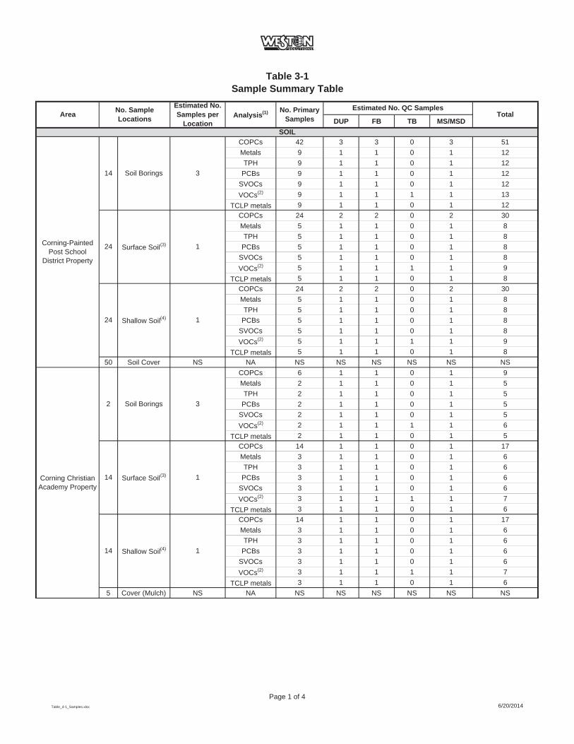
Table 3-1Sample Summary Table
DUP FB TB MS/MSD
COPCs 42 3 3 0 3 51Metals 9 1 1 0 1 12TPH 9 1 1 0 1 12
PCBs 9 1 1 0 1 12SVOCs 9 1 1 0 1 12VOCs(2) 9 1 1 1 1 13
TCLP metals 9 1 1 0 1 12COPCs 24 2 2 0 2 30Metals 5 1 1 0 1 8TPH 5 1 1 0 1 8
PCBs 5 1 1 0 1 8SVOCs 5 1 1 0 1 8VOCs(2) 5 1 1 1 1 9
TCLP metals 5 1 1 0 1 8COPCs 24 2 2 0 2 30Metals 5 1 1 0 1 8TPH 5 1 1 0 1 8
PCBs 5 1 1 0 1 8SVOCs 5 1 1 0 1 8VOCs(2) 5 1 1 1 1 9
TCLP metals 5 1 1 0 1 850 Soil Cover NS NA NS NS NS NS NS NS
COPCs 6 1 1 0 1 9Metals 2 1 1 0 1 5TPH 2 1 1 0 1 5
PCBs 2 1 1 0 1 5SVOCs 2 1 1 0 1 5VOCs(2) 2 1 1 1 1 6
TCLP metals 2 1 1 0 1 5COPCs 14 1 1 0 1 17Metals 3 1 1 0 1 6TPH 3 1 1 0 1 6
PCBs 3 1 1 0 1 6SVOCs 3 1 1 0 1 6VOCs(2) 3 1 1 1 1 7
TCLP metals 3 1 1 0 1 6COPCs 14 1 1 0 1 17Metals 3 1 1 0 1 6TPH 3 1 1 0 1 6
PCBs 3 1 1 0 1 6SVOCs 3 1 1 0 1 6VOCs(2) 3 1 1 1 1 7
TCLP metals 3 1 1 0 1 65 Cover (Mulch) NS NA NS NS NS NS NS NS
Shallow Soil(4) 1
Shallow Soil(4) 1
Corning Christian Academy Property
2 Soil Borings 3
14 Surface Soil(3) 1
14
Total
SOIL
Corning-PaintedPost School
District Property
14 Soil Borings 3
24 Surface Soil(3) 1
24
Area No. Sample Locations
Estimated No. Samples per
LocationAnalysis(1) No. Primary
SamplesEstimated No. QC Samples
Table_4-1_Samples.xlsx
Page 1 of 46/20/2014

Table 3-1 (continued)Sample Summary Table
DUP FB TB MS/MSDTotalArea No. Sample
Locations
Estimated No. Samples per
LocationAnalysis(1) No. Primary
SamplesEstimated No. QC Samples
COPCs 9 1 1 0 1 12Metals 2 1 1 0 1 5TPH 2 1 1 0 1 5
PCBs 2 1 1 0 1 5SVOCs 2 1 1 0 1 5VOCs(2) 2 1 1 1 1 6
TCLP metals 2 1 1 0 1 5COPCs 17 1 1 0 1 20Metals 4 1 1 0 1 7TPH 4 1 1 0 1 7
PCBs 4 1 1 0 1 7SVOCs 4 1 1 0 1 7VOCs(2) 4 1 1 1 1 8
TCLP metals 4 1 1 0 1 7COPCs 17 1 1 0 1 20Metals 4 1 1 0 1 7TPH 4 1 1 0 1 7
PCBs 4 1 1 0 1 7SVOCs 4 1 1 0 1 7VOCs(2) 4 1 1 1 1 8
TCLP metals 4 1 1 0 1 7COPCs 9 1 1 0 1 12Metals 2 1 1 0 1 5TPH 2 1 1 0 1 5
PCBs 2 1 1 0 1 5SVOCs 2 1 1 0 1 5VOCs(2) 2 1 1 1 1 6
TCLP metals 2 1 1 0 1 5COPCs 5 1 1 0 1 8Metals 1 1 1 0 1 4TPH 1 1 1 0 1 4
PCBs 1 1 1 0 1 4SVOCs 1 1 1 0 1 4VOCs(2) 1 1 1 1 1 5
TCLP metals 1 1 1 0 1 4COPCs 5 1 1 0 1 8Metals 1 1 1 0 1 4TPH 1 1 1 0 1 4
PCBs 1 1 1 0 1 4SVOCs 1 1 1 0 1 4VOCs(2) 1 1 1 1 1 5
TCLP metals 1 1 1 0 1 4
Shallow Soil(4) 1
Shallow Soil(4) 1
FirehouseFrontage Property
3 Soil Borings 3
5 Surface Soil(3) 1
5
Memorial Stadium Property
3 Soil Borings 3
17 Surface Soil(3) 1
17
Table_4-1_Samples.xlsx
Page 2 of 46/20/2014

Table 3-1 (continued)Sample Summary Table
DUP FB TB MS/MSDTotalArea No. Sample
Locations
Estimated No. Samples per
LocationAnalysis(1) No. Primary
SamplesEstimated No. QC Samples
COPCs 33 2 2 0 2 39Metals 15 1 1 0 1 18TPH 15 1 1 0 1 18
PCBs 15 1 1 0 1 18SVOCs 15 1 1 0 1 18VOCs(2) 15 1 1 1 1 19
TCLP metals 15 1 1 0 1 18COPCs 12 1 1 0 1 15Metals 5 1 1 0 1 8TPH 5 1 1 0 1 8
PCBs 5 1 1 0 1 8SVOCs 5 1 1 0 1 8VOCs(2) 5 1 1 1 1 9
TCLP metals 5 1 1 0 1 8COPCs 72 4 4 0 4 84Metals 15 1 1 0 1 18TPH 15 1 1 0 1 18
PCBs 15 1 1 0 1 18SVOCs 15 1 1 0 1 18VOCs(2) 15 1 1 1 1 19
TCLP metals 15 1 1 0 1 18COPCs 866 44 44 0 44 998Metals 214 11 11 0 11 247TPH 214 11 11 0 11 247
PCBs 214 11 11 0 11 247SVOCs 214 11 11 0 11 247VOCs(2) 214 11 11 1 11 248
TCLP metals 214 11 11 0 11 24715 Cover (Mulch) NS NA NS NS NS NS NS NS
3,594TOTAL SOIL ANALYSES:
Residential Area (including
Houghton Park)
24 Soil Borings 3
866 Surface Soil(3) 1
Residential Area at East End of Corning Blvd
11 Soil Borings 3
12 Surface Soil(3) 1
Table_4-1_Samples.xlsx
Page 3 of 46/20/2014

Table 3-1 (continued)Sample Summary Table
DUP FB TB MS/MSDTotalArea No. Sample
Locations
Estimated No. Samples per
LocationAnalysis(1) No. Primary
SamplesEstimated No. QC Samples
COPCs 10 2 0 0 2 14Metals 2 2 0 0 2 6TPH 2 2 0 0 2 6PAH 2 2 0 0 2 6PCBs 2 2 0 0 2 6VOCs 2 2 0 2 2 8
COPCs 8 2 0 0 2 12Metals 2 2 0 0 2 6TPH 2 2 0 0 2 6PAH 2 2 0 0 2 6PCBs 2 2 0 0 2 6VOCs 2 2 0 2 2 8
90
Notes:(1) - Analytical methods are presented in Table 4-2 and complete analyte lists are presented in Table 4-3.(2) - VOCs collected at highest concentration(s) in borings where photoionization detector readings are >5X background(3) - Surface samples collected from 0 - 2 inches bgs(4) - Shallow samples collected from 2 inches bgs to 2 feet bgsNo samples collected of soil cover - confirmation of existence and thickness onlyTPH - Total Petroleum HydrocarbonsPAH - Polycyclic aromatic hydrocarbonsPCB - Polychlorinated biphenylsCOPCs - Constituents of Potential Concern (i.e., arsenic, cadmium and lead)QA/QC - quality assurance/quality controlDUP - duplicate sampleFB - field blankMS/MSD - matrix spike/matrix spike duplicateTB - trip blankNo. - numberbgs - below ground surfaceNA - not applicable (no analytical samples collected)NS - not sampled
Assumptions:All samples analyzed for list (as shown)All samples analyzed for COPCs, 20% of samples analyzed for full listDUP, FB and MS/MSD collected at 20% TB is 1 per VOC cooler (assume 1 per area)
Residential Area at East End of Corning Blvd
4 MonitoringWells 2
TOTAL GROUNDWATER ANALYSES:
GROUNDWATER
School Area 5 MonitoringWells 2
Table_4-1_Samples.xlsx
Page 4 of 46/20/2014
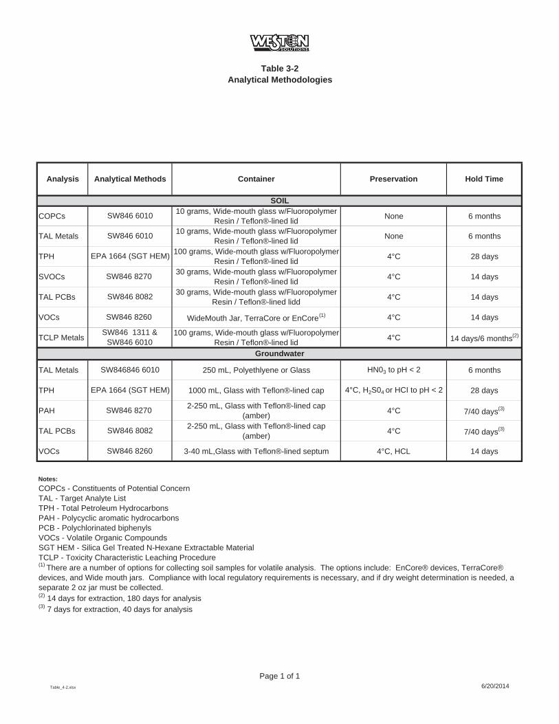
Table 3-2Analytical Methodologies
COPCs 10 grams, Wide-mouth glass w/Fluoropolymer Resin / Teflon®-lined lid None 6 months
TAL Metals 10 grams, Wide-mouth glass w/Fluoropolymer Resin / Teflon®-lined lid None 6 months
TPH 100 grams, Wide-mouth glass w/Fluoropolymer Resin / Teflon®-lined lid 4°C 28 days
SVOCs 30 grams, Wide-mouth glass w/Fluoropolymer Resin / Teflon®-lined lid 4°C 14 days
TAL PCBs 30 grams, Wide-mouth glass w/Fluoropolymer Resin / Teflon®-lined lidd 4°C 14 days
VOCs WideMouth Jar, TerraCore or EnCore(1) 4°C 14 days
TCLP Metals 100 grams, Wide-mouth glass w/Fluoropolymer Resin / Teflon®-lined lid 4°C 14 days/6 months(2)
TAL Metals 250 mL, Polyethlyene or Glass HN03 to pH < 2 6 months
TPH 1000 mL, Glass with Teflon®-lined cap 4°C, H2S04 or HCI to pH < 2 28 days
PAH 2-250 mL, Glass with Teflon®-lined cap (amber) 4°C 7/40 days(3)
TAL PCBs 2-250 mL, Glass with Teflon®-lined cap (amber) 4°C 7/40 days(3)
VOCs 3-40 mL,Glass with Teflon®-lined septum 4°C, HCL 14 days
Notes:COPCs - Constituents of Potential ConcernTAL - Target Analyte ListTPH - Total Petroleum HydrocarbonsPAH - Polycyclic aromatic hydrocarbonsPCB - Polychlorinated biphenylsVOCs - Volatile Organic CompoundsSGT HEM - Silica Gel Treated N-Hexane Extractable Material TCLP - Toxicity Characteristic Leaching Procedure
(2) 14 days for extraction, 180 days for analysis(3) 7 days for extraction, 40 days for analysis
Hold Time
SOIL
SW846 8260
Analysis Analytical Methods Container Preservation
SW846 6010
SW846 6010
EPA 1664 (SGT HEM)
SW846 8270
SW846 8082
SW846 8260
(1) There are a number of options for collecting soil samples for volatile analysis. The options include: EnCore® devices, TerraCore® devices, and Wide mouth jars. Compliance with local regulatory requirements is necessary, and if dry weight determination is needed, a separate 2 oz jar must be collected.
SW846 1311 &SW846 6010
Groundwater
SW846846 6010
EPA 1664 (SGT HEM)
SW846 8270
SW846 8082
Table_4-2.xlsx
Page 1 of 16/20/2014

Site
Loc
atio
nSa
mpl
e Ty
peSa
mpl
e A
rea
Sam
ple
Num
ber
QC
Typ
eD
epth
/Loc
atio
n/D
ate
Dat
eC
ON
Y -
Cor
ning
, NY
SS
- Soi
l Sam
ple
CP
P =
Cor
ning
-Pai
nted
Pos
t Sch
ool D
istri
ct P
rope
rty
SS
###
- Soi
l Sam
ple
#0
- Prim
ary
Sam
ple
####
- D
epth
at T
op o
f Sam
ple
YY
MM
DD
= Y
ear/M
onth
/Dat
eS
B-S
oil B
orin
gC
CA
= C
orni
ng C
hris
tian
Aca
dem
yS
B##
# - S
oil B
orin
g #
FB- F
ield
Bla
nk S
ampl
e(e
.g. 2
.0 ft
is 0
020)
RO
W =
Rig
ht-o
f-Way
Are
aM
S-M
atrix
Spi
keC
MS
= M
emor
ial S
tadi
um A
rea
MS
D-M
atrix
Spi
ke D
uplic
ate
FFR
= F
ireho
use
Fron
tage
DU
P -
Dup
licat
e S
ampl
eR
ES
= R
esid
entia
l Are
aFC
A =
Flo
od C
ontro
l Are
aE
xam
ple
ID:
CO
NY
-SB
-EE
CS
B05
-0-0
002-
1406
01P
rimar
y so
il sa
mpl
e co
llect
ed fr
om s
oil b
orin
g #5
in th
e E
aste
rn E
nd o
f Cor
ning
Blv
d A
rea
colle
cted
at 0
.2 ft
bgs
on
June
1, 2
014
Site
Loc
atio
nSa
mpl
e Ty
peSa
mpl
e A
rea
Sam
ple
Loca
tion
QC
Typ
eD
ate
CO
NY
- C
orni
ng, N
YG
W -
Gro
undw
ater
Sam
ple
CP
P =
Cor
ning
-Pai
nted
Pos
t Sch
ool D
istri
ct P
rope
rty
MW
## -
Tem
pora
ry W
ell S
ampl
e P
oint
0 - P
rimar
y S
ampl
eY
YM
MD
D =
Yea
r/Mon
th/D
ate
CC
A =
Cor
ning
Chr
istia
n A
cade
my
TRIP
## -T
rip B
lank
Sam
ple
Poi
ntFB
- Fi
eld
Bla
nk S
ampl
eR
OW
= R
ight
-of-W
ay A
rea
FIE
LD##
- Fi
eld
Bla
nk S
ampl
e P
oint
TB -
Trip
Bla
nk S
ampl
eC
MS
= M
emor
ial S
tadi
um A
rea
MS
- M
atrix
Spi
keFF
R =
Fire
hous
e Fr
onta
geM
SD
- M
atrix
Spi
ke D
uplic
ate
RE
S =
Res
iden
tial A
rea
DU
P -
Dup
licat
e S
ampl
eFC
A =
Flo
od C
ontro
l Are
aE
xam
ple
ID:
CO
NY
-GW
-CP
PM
W01
-0-1
4060
1P
rimar
y gr
ound
wat
er s
ampl
e co
llect
ed fr
om m
onito
ring
wel
l #1
in th
e C
orni
ng-P
aint
ed P
ost S
choo
l Dis
trict
Are
a on
Jun
e 1,
201
4
Soil
Sam
ples
Tabl
e 3-
3 F
ield
Sam
ple
Iden
tifie
rs
Wat
er S
ampl
es
QA
PP
Tab
le 3
-3.x
lsP
age
1 of
16/
20/2
014

FIG
UR
E 3-
1 T
estA
mer
ica
Cha
in-o
f-Cus
tody

2014_CNY_SCWP_APP_C_QAPP_FINAL.docx 6/20/2014 4-1
4. FIELD OPERATIONS
This section includes brief descriptions of field procedures used to conduct environmental
evaluations at the Study Area. Criteria or guidelines for choosing among alternatives are also
included when more than one procedure can be used.
4.1 FIELD RECORDS
Documentation of field sampling will be performed to ensure data validity and facilitate analysis
and evaluation. Examples of field documentation are provided in the following sections.
Field personnel are responsible for recording field activities in the appropriate field documentation
logbooks or dedicated sampling sheets in sufficient detail to allow the significant aspects of the
event to be reconstructed without relying on memory. It is the responsibility of the Field Team
Manager to ensure that documents are complete and legible.
The field documentation forms or equivalent records that will be used during this investigation
include the following:
Soil sampling and borehole log forms;
Field logbooks;
Annotation of maps; and
Sample chain-of-custody record.
4.1.1 Field Logbooks
Field logbooks will be used to record data collection activities. Activities will be described in as
much detail as possible so that persons going to the facility can reconstruct a particular situation
without relying on memory.
A field logbook(s) will be maintained by the Field Team Manager or designated field team
members present in the field to record information pertinent to daily activities, the field sampling

2014_CNY_SCWP_APP_C_QAPP_FINAL.docx 6/20/2014 4-2
program, and the equipment preparation efforts. Field logbooks will be bound, pages numbered, and
entries made in permanent, waterproof ink. Designated field sheets may also be used to record
project activities. Field logbooks and field sheets will be scanned and transferred to the electronic
project files or physically placed in the file at the end of field activities to provide a record of
sampling.
Field logbooks and/or field sampling sheets will contain the following types of information, where
applicable:
Name and location of project.
Date(s) and time(s) of sample collection.
Name of Field Team Manager and/or other field team members.
Field observations, including physical/environmental conditions during the field activity (i.e., weather).
Summary of equipment preparation/decontamination procedures.
Number, type, location, depth, and analysis required of samples taken and sample identification codes.
A description of sampling methodologies or references to the Work Plan and this QAPP.
A cross-reference to photographs, if photographs are taken.
Sample container/preservative.
A cross-reference of sample identification codes or sampling points on annotated project maps or sketches.
Sample shipping dates and methods.
Deviations from the Work Plan (if applicable).
Comments and other relevant observations such as weather conditions or other factors that may
affect sample results or interpretation of sampling techniques and any modifications to sampling
procedures as well as other technical comments regarding color, odor, texture, moisture and
other sample characteristics.

2014_CNY_SCWP_APP_C_QAPP_FINAL.docx 6/20/2014 4-3
4.1.2 Soil Sampling and Borehole Log Forms
Certain descriptive and sample information will be recorded during the completion of each boring
and the collection/logging of soil samples. The information will be recorded in the field logbook, on
a soil description form, borehole log form, or other appropriate form.
4.1.3 Corrections to Documentation
Field measurements made and samples collected will be recorded. Corrections will be made by
drawing a line through the incorrect entry and writing in the correct entry. The person making the
correction will date and initial the correction. There will be no erasures or deletions from the field
logbooks.
4.2 SURVEYING
Any monitoring wells installed will be surveyed by a licensed surveyor, including horizontal
coordinates, ground surface elevation, top of inner casing (riser) elevation, and top of outer
protective casing elevation. The elevations will be reported to the nearest 0.01 foot.
Land-based survey methods will be used to establish a benchmark and a reference point to USGS
datum. The data will be used along with depth to groundwater data to further define groundwater
elevations within the Study Area.
Surface soil and soil boring locations will be recorded using a hand-held GPS unit with sub-meter
accuracy.
4.3 ANNOTATION OF MAPS
Copies of Study Area base maps or sketches used by the field teams to record key Study Area
conditions and to show approximate locations of soil borings, monitoring wells, buildings and
structures, utilities, and other appropriate project location information will be maintained (as
needed) for the project files. The maps or sketches will be maintained by the Field Team Manager
during field activities and transferred to the project files for a record of sampling locations.

2014_CNY_SCWP_APP_C_QAPP_FINAL.docx 6/20/2014 4-4
4.4 AIR MONITORING
In accordance with the CAMP, air monitoring will be conducted to evaluate air quality during
project activities (as needed). The data provided by the air monitoring could be used to determine
the appropriate control actions and personal protective equipment (PPE) requirements.
Equipment calibration of air monitoring equipment will be performed in accordance with the
manufacturer instructions.
A PID equipped with a 10.6 eVor an 11.7 eV lamp, calibrated with isobutylene, will be used to
monitor the general area and the breathing zone of workers during intrusive activities to assess
the potential presence of organic vapors.
4.5 FIELD CALIBRATION
Field instrumentation will be calibrated in accordance with the manufacturer supplied guidance
manual to ensure that the instruments are operating properly and produce data that can satisfy the
objectives of the sampling program. Specific field instruments that will be used during the
project, when appropriate, include the following:
Water level indicator;
PID meter; and
PM10 Dust Monitor.
To ensure that the instruments are operating properly and are producing accurate and reliable
data, routine calibration must be performed. Calibrations should be performed at a frequency
recommended by the manufacturer. Calibration procedures are normally included with the
equipment. Field calibrations should be performed at the beginning of the day and should be
checked throughout the sampling day.
PID meters and PM10 dust meters will be calibrated according to the instrument manufacturers'
specifications. Daily calibrations will be performed by WESTON personnel. The recorded
2014_CNY_SCWP_APP_C_QAPP_FINAL.docx 6/20/2014 4-5
calibration information includes date of calibration, standards used, and calibration results will
be recorded in the field logbook or designated field calibration sheets.
Groundwater Sampling Instruments
WESTON will use field instruments when conducting groundwater sampling activities.
WESTON’s field instrumentation will be calibrated to ensure that the instruments are operating
properly and produce data that satisfy the objectives of the sampling program. Specific field
instruments that will be used, when appropriate, include the following:
pH meter;
Conductivity meter;
Thermometer or temperature sensor;
Dissolved oxygen meter; and
Oxidation-reduction potential meter.
If field calibration reveals that any of the instruments are outside established accuracy limits, the
instrument will be serviced in the field according to the manufacturer’s specifications as
possible. If necessary, the instrument will be returned to the manufacturer for repair and
servicing.
2014_CNY_SCWP_APP_C_QAPP_FINAL.docx 6/20/2014 5-1
5. LABORATORY ANALYSIS
To generate analytical data of known and defensible quality, adherence to established QA protocols
will be used. To ensure that the samples obtained in the field represent the particular environment
from which they are collected and are of satisfactory quality, laboratory analysis will be performed
in accordance with the Work Plan SOPs as well as in accordance with TestAmerica laboratory
SOPs established in TestAmerica’s QAM provided in Attachment A of this QAPP.
5.1 LABORATORY REQUIREMENTS
TestAmerica (certified New York laboratory #10026) will perform analysis on environmental
samples where certification exists. The laboratory will follow QA/QC procedures specified by the
analytical methods. Analytical results will meet the method detection limits (MDLs) specified by
the analytical methods.
5.2 METHOD DETECTION LIMITS
To generate data that meets the project-specific data quality objectives, the laboratory will
demonstrate the sensitivities of the methodologies used for sample analyses will be at or below
the method detection limits (i.e., MDLs). Table 5-1 summarizes the laboratory MDLs.
The method detection limit (MDL) is the minimum concentration of a substance that can be
measured and reported with 99% confidence that the analyte concentration is greater than non
detect (ND) and is determined from analysis of a sample in a given matrix containing the
analyte. The MDL is estimated in an interference-free matrix, typically reagent water for water
methods and a purified solid matrix (e.g., sand) for soil methods and shall be estimated for each
compounds/analytes of interest using the procedures presented in 40 CFR, Part 136, Appendix B.
The MDLs are extraction/digestion method-specific and includes any clean-up methods used.
The laboratory performs MDL studies whenever the basic chemistry of the procedures changes.
If any of the target analytes are not recovered, the MDL study will be repeated for the failed
target analytes. The MDL study is performed at a minimum, on an annual basis.
2014_CNY_SCWP_APP_C_QAPP_FINAL.docx 6/20/2014 5-2
5.3 ANALYTICAL METHODS AND HOLDING TIMES
Table 3-2 summarizes the analytical methods to be used and the maximum holding times for
water and soil samples. Sample holding times are calculated from the time of collection.
Samples collected under this QAPP will be analyzed using procedures of U.S. Environmental
Protection Agency (USEPA) SW-846, 3rd Edition, Final Update III, December 1996 (SW-846),
USEPA Methods for Chemical Analyses of Waters and Wastes (MCAWW), or American
Society of Testing and Materials (ASTM).
5.4 QUALITY CONTROL AND QUALITY ASSURANCE
Sample analyses will include a method blank, a method blank spike, a matrix spike, a laboratory
duplicate for inorganic analyses (or matrix spike duplicate for organic analyses), and a laboratory
control standard (inorganic analysis only) in each batch of 20 or fewer samples. In addition,
appropriate surrogate compounds (organic analysis only) will be spiked into each sample.
Recoveries from matrix spikes and surrogate compounds are calculated and recorded on control
charts to maintain a history of system performance. The laboratory-performance-based
acceptable limits for each compounds/analytes will be established and provided by the
laboratory.
Any blanks and/or other QC parameters not meeting the established acceptance criteria will
prompt sample re-extraction/re-digestion and /or reanalysis as detailed in the laboratory SOPs
that are included with TestAmerica’s QA Manual in Attachment A of this QAPP.
Before any instrument is used as a measurement device on the project samples, the instrument
responses to known reference materials will be determined. The manner in which various
instruments are calibrated is dependent upon the particular type of instrument and its intended
use. Sample measurements are made within the calibrated range of the instrument. Preparation of
reference materials used for calibration will be documented in the standards preparation
notebook.

2014_CNY_SCWP_APP_C_QAPP_FINAL.docx 6/20/2014 5-3
Instrument initial calibration will be performed to the pertinent method specifications or the
manufacturing manual. Continuing calibration or calibration verification will be performed at
frequencies outlined in the pertinent analytical methods. The acceptance criteria will be met
before any samples are analyzed.
Details on TestAmerica’s quality control/quality assurance program are provided in its QAM
(see Attachment A of this QAPP).
5.5 DATA REPORTING
Laboratory data deliverables will consist of analytical data in tabulated forms as well as the
complete laboratory data deliverable package. TestAmerica will produce laboratory data packages
which meet the requirements of NYSDEC Analytical Services Protocol (ASP) Category B (See
DER-10 Appendix 2B Section 1.0b).
Additionally, TestAmerica will provide an electronic data delivery (EDD) for all samples with QC
sample data to be utilized during the data review/validation activities.
5.6 DATA REVIEW/VALIDATION
All laboratory data deliverable packages will be reviewed for completeness, adherence to holding
times, comparison with chain-of-custody, etc. Laboratory data package reviews may include the
following activities:
Review of laboratory supplied data package for completeness
Review of chain-of-custody documents to verify sample identities.
Review of sample log-in documents to identify any potential problems with custody seals, container integrity, sample preservation, labeling, etc.
Review of sample analysis methods and holding times.
Review of field blank and trip blank data to identify any potential problems with sampling devices contamination, sample container contamination, preservative contamination, laboratory reagent water contamination, or cross-contamination between samples during transport.

2014_CNY_SCWP_APP_C_QAPP_FINAL.docx 6/20/2014 5-4
Review of method blank data to determine the presence of any sources of contamination in the analytical process, where applicable.
Review of MS/MSD data to evaluate the potential for matrix effects as a measure of analytical accuracy and sample homogeneity as a measure of analytical precision. MS/MSD data will be compared to laboratory acceptance criteria for the maximum relative percent difference (RPD), where applicable.
Review of blank spike and blank spike duplicate (BS/BSD) data as a measure of analytical accuracy and as a measure of analytical precision, where applicable. BS/BSD data will be compared to laboratory acceptance criteria for the maximum RPD.
Review of laboratory control sample (LCS) data as a measure of analytical accuracy, where applicable. LCS data will be compared to the certified acceptable ranges of analytical values.
Review of sample and sample duplicate data as a measure of sample homogeneity and as a measure of analytical precision.
Review of surrogate recovery data to assess analytical performance, where applicable.. Surrogate recoveries will be compared to laboratory acceptance criteria to determine if they are within or outside of acceptable limits.
Determine completeness as a percentage of measurements made which are judged to be valid measurements compared to the total number of measurements planned, where applicable.
Review data summary sheets and qualifiers for consistency with raw data and qualifier definitions.
Data validation will be performed, and a DUSR will be prepared in accordance with DER-10
Appendix 2B. This DUSR will be prepared by a scientist capable of conducting a full data
validation. The DUSR will provide the assessment included in the initial data review discussed
above, with further related QA/QC information consideration, enabling full evaluation of the
analytical data’s usability and quality.
The data validation/review process will be documented through DUSRs and submission of the
analytical data packages and DUSRs to the NYSDEC. Final and validated/reviewed analytical
data, including applicable qualifiers will be summarized in tables for associated project
characterization summary reports.
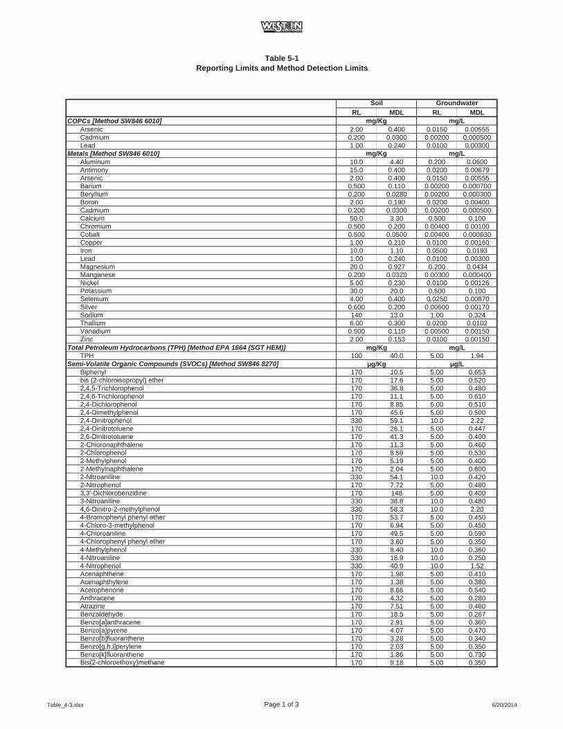
Table 5-1Reporting Limits and Method Detection Limits
RL MDL RL MDLCOPCs [Method SW846 6010]
Arsenic 2.00 0.400 0.0150 0.00555Cadmium 0.200 0.0300 0.00200 0.000500Lead 1.00 0.240 0.0100 0.00300
Metals [Method SW846 6010]Aluminum 10.0 4.40 0.200 0.0600Antimony 15.0 0.400 0.0200 0.00679Arsenic 2.00 0.400 0.0150 0.00555Barium 0.500 0.110 0.00200 0.000700Beryllium 0.200 0.0280 0.00200 0.000300Boron 2.00 0.190 0.0200 0.00400Cadmium 0.200 0.0300 0.00200 0.000500Calcium 50.0 3.30 0.500 0.100Chromium 0.500 0.200 0.00400 0.00100Cobalt 0.500 0.0500 0.00400 0.000630Copper 1.00 0.210 0.0100 0.00160Iron 10.0 1.10 0.0500 0.0193Lead 1.00 0.240 0.0100 0.00300Magnesium 20.0 0.927 0.200 0.0434Manganese 0.200 0.0320 0.00300 0.000400Nickel 5.00 0.230 0.0100 0.00126Potassium 30.0 20.0 0.500 0.100Selenium 4.00 0.400 0.0250 0.00870Silver 0.600 0.200 0.00600 0.00170Sodium 140 13.0 1.00 0.324Thallium 6.00 0.300 0.0200 0.0102Vanadium 0.500 0.110 0.00500 0.00150Zinc 2.00 0.153 0.0100 0.00150
Total Petroleum Hydrocarbons (TPH) [Method EPA 1664 (SGT HEM)]TPH 100 40.0 5.00 1.94
Semi-Volatile Organic Compounds (SVOCs) [Method SW846 8270]Biphenyl 170 10.5 5.00 0.653bis (2-chloroisopropyl) ether 170 17.6 5.00 0.5202,4,5-Trichlorophenol 170 36.8 5.00 0.4802,4,6-Trichlorophenol 170 11.1 5.00 0.6102,4-Dichlorophenol 170 8.85 5.00 0.5102,4-Dimethylphenol 170 45.6 5.00 0.5002,4-Dinitrophenol 330 59.1 10.0 2.222,4-Dinitrotoluene 170 26.1 5.00 0.4472,6-Dinitrotoluene 170 41.3 5.00 0.4002-Chloronaphthalene 170 11.3 5.00 0.4602-Chlorophenol 170 8.59 5.00 0.5302-Methylphenol 170 5.19 5.00 0.4002-Methylnaphthalene 170 2.04 5.00 0.6002-Nitroaniline 330 54.1 10.0 0.4202-Nitrophenol 170 7.72 5.00 0.4803,3'-Dichlorobenzidine 170 148 5.00 0.4003-Nitroaniline 330 38.8 10.0 0.4804,6-Dinitro-2-methylphenol 330 58.3 10.0 2.204-Bromophenyl phenyl ether 170 53.7 5.00 0.4504-Chloro-3-methylphenol 170 6.94 5.00 0.4504-Chloroaniline 170 49.5 5.00 0.5904-Chlorophenyl phenyl ether 170 3.60 5.00 0.3504-Methylphenol 330 9.40 10.0 0.3604-Nitroaniline 330 18.9 10.0 0.2504-Nitrophenol 330 40.9 10.0 1.52Acenaphthene 170 1.98 5.00 0.410Acenaphthylene 170 1.38 5.00 0.380Acetophenone 170 8.66 5.00 0.540Anthracene 170 4.32 5.00 0.280Atrazine 170 7.51 5.00 0.460Benzaldehyde 170 18.5 5.00 0.267Benzo[a]anthracene 170 2.91 5.00 0.360Benzo[a]pyrene 170 4.07 5.00 0.470Benzo[b]fluoranthene 170 3.28 5.00 0.340Benzo[g,h,i]perylene 170 2.03 5.00 0.350Benzo[k]fluoranthene 170 1.86 5.00 0.730Bis(2-chloroethoxy)methane 170 9.18 5.00 0.350
mg/Kg mg/L
μg/Kg μg/L
Soil Groundwater
mg/Kg mg/L
mg/Kg mg/L
Table_4-3.xlsx Page 1 of 3 6/20/2014

Table 5-1 (continued)Reporting Limits and Method Detection Limits
RL MDL RL MDLSoil Groundwater
Semi-Volatile Organic Compounds (SVOCs) [Method SW846 8270] (continued)Bis(2-chloroethyl)ether 170 14.6 5.00 0.400Bis(2-ethylhexyl) phthalate 170 54.4 5.00 1.80Butyl benzyl phthalate 170 45.3 5.00 0.420Caprolactam 170 73.0 5.00 2.20Carbazole 170 1.95 5.00 0.300Chrysene 170 1.69 5.00 0.330Dibenz(a,h)anthracene 170 1.99 5.00 0.420Di-n-butyl phthalate 170 58.3 5.00 0.310Di-n-octyl phthalate 170 3.95 5.00 0.470Dibenzofuran 170 1.76 10.0 0.510Diethyl phthalate 170 5.10 5.00 0.220Dimethyl phthalate 170 4.40 5.00 0.360Fluoranthene 170 2.45 5.00 0.400Fluorene 170 3.89 5.00 0.360Hexachlorobenzene 170 8.39 5.00 0.510Hexachlorobutadiene 170 8.64 5.00 0.680Hexachlorocyclopentadiene 170 51.0 5.00 0.590Hexachloroethane 170 13.1 5.00 0.590Indeno[1,2,3-cd]pyrene 170 4.67 5.00 0.470Isophorone 170 8.44 5.00 0.430N-Nitrosodi-n-propylamine 170 13.4 5.00 0.540N-Nitrosodiphenylamine 170 9.23 5.00 0.510Naphthalene 170 2.81 5.00 0.760Nitrobenzene 170 7.48 5.00 0.290Pentachlorophenol 330 57.9 10.0 2.20Phenanthrene 170 3.54 5.00 0.440Phenol 170 17.8 5.00 0.390Pyrene 170 1.09 5.00 0.3402-Fluorobiphenyl
Polychlorinated Biphenyls (PCBs) [Method SW846 8082]PCB-1016 0.0167 0.00326 0.500 0.176PCB-1221 0.0167 0.00326 0.500 0.176PCB-1232 0.0167 0.00326 0.500 0.176PCB-1242 0.0167 0.00326 0.500 0.176PCB-1248 0.0167 0.00326 0.500 0.176PCB-1254 0.0167 0.00782 0.500 0.250PCB-1260 0.0167 0.00782 0.500 0.250PCB-1262 0.0167 0.00782 0.500 0.250PCB-1268 0.0167 0.00782 0.500 0.250
Volatile Organic Compounds (VOCs) [Method SW846 8260]1,1,1-Trichloroethane 5.00 0.363 1.00 0.8201,1,2,2-Tetrachloroethane 5.00 0.811 1.00 0.2101,1,2-Trichloroethane 5.00 0.650 1.00 0.2301,1,2-Trichloro-1,2,2-trifluoroethane 5.00 1.14 1.00 0.3101,1-Dichloroethane 5.00 0.610 1.00 0.3801,1-Dichloroethene 5.00 0.612 1.00 0.2901,2,4-Trichlorobenzene 5.00 0.304 1.00 0.4101,2-Dibromo-3-Chloropropane 5.00 2.50 1.00 0.3901,2-Dichlorobenzene 5.00 0.391 1.00 0.7901,2-Dichloroethane 5.00 0.251 1.00 0.2101,2-Dichloropropane 5.00 2.50 1.00 0.7201,3-Dichlorobenzene 5.00 0.257 1.00 0.7801,4-Dichlorobenzene 5.00 0.700 1.00 0.8402-Butanone (MEK) 25.0 1.83 10.0 1.322-Hexanone 25.0 2.50 5.00 1.244-Methyl-2-pentanone (MIBK) 25.0 1.64 5.00 2.10Acetone 25.0 4.21 10.0 3.00Benzene 5.00 0.245 1.00 0.410Bromodichloromethane 5.00 0.670 1.00 0.390Bromoform 5.00 2.50 1.00 0.260Bromomethane 5.00 0.450 1.00 0.690Carbon disulfide 5.00 2.50 1.00 0.190Carbon tetrachloride 5.00 0.484 1.00 0.270Chlorobenzene 5.00 0.660 1.00 0.750Dibromochloromethane 5.00 0.640 1.00 0.320Chloroethane 5.00 1.13 1.00 0.320Chloroform 5.00 0.309 1.00 0.340
mg/Kg ug/L
ug/Kg ug/L
μg/Kg μg/L
Table_4-3.xlsx Page 2 of 3 6/20/2014
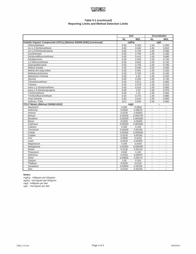
Table 5-1 (continued)Reporting Limits and Method Detection Limits
RL MDL RL MDLSoil Groundwater
Volatile Organic Compounds (VOCs) [Method SW846 8260] (continued)Chloromethane 5.00 0.302 1.00 0.350cis-1,2-Dichloroethene 5.00 0.640 1.00 0.810cis-1,3-Dichloropropene 5.00 0.720 1.00 0.360Cyclohexane 5.00 0.700 1.00 0.180Dichlorodifluoromethane 5.00 0.413 1.00 0.680Ethylbenzene 5.00 0.345 1.00 0.7401,2-Dibromoethane 5.00 0.642 1.00 0.730Isopropylbenzene 5.00 0.754 1.00 0.790Methyl acetate 5.00 0.930 2.50 0.500Methyl tert-butyl ether 5.00 0.491 1.00 0.160Methylcyclohexane 5.00 0.760 1.00 0.160Methylene Chloride 5.00 2.30 1.00 0.440Styrene 5.00 0.250 1.00 0.730Tetrachloroethene 5.00 0.671 1.00 0.360Toluene 5.00 0.378 1.00 0.510trans-1,2-Dichloroethene 5.00 0.516 1.00 0.900trans-1,3-Dichloropropene 5.00 2.20 1.00 0.370Trichloroethene 5.00 1.10 1.00 0.460Trichlorofluoromethane 5.00 0.473 1.00 0.880Vinyl chloride 5.00 0.610 1.00 0.900Xylenes, Total 10.0 0.840 2.00 0.660
TCLP Metals [Method SW846 6010]Aluminum 0.200 0.0600 -- --Antimony 0.0200 0.00679 -- --Arsenic 0.0150 0.00555 -- --Barium 0.00200 0.000700 -- --Beryllium 0.00200 0.000300 -- --Boron 0.0200 0.00400 -- --Cadmium 0.00200 0.000500 -- --Calcium 0.500 0.100 -- --Chromium 0.00400 0.00100 -- --Cobalt 0.00400 0.000630 -- --Copper 0.0100 0.00160 -- --Iron 0.0500 0.0193 -- --Lead 0.0100 0.00300 -- --Magnesium 0.200 0.0434 -- --Manganese 0.00300 0.000400 -- --Nickel 0.0100 0.00126 -- --Potassium 0.500 0.100 -- --Selenium 0.0250 0.00870 -- --Silver 0.00600 0.00170 -- --Sodium 1.00 0.324 -- --Thallium 0.0200 0.0102 -- --Vanadium 0.00500 0.00150 -- --Zinc 0.0100 0.00150 -- --
Notes:mg/Kg - milligram per kilogramug/Kg - microgram per kilogrammg/L- milligram per literug/L - microgram per liter
mg/L --
ug/Kg ug/L
Table_4-3.xlsx Page 3 of 3 6/20/2014

2014_CNY_SCWP_APP_C_QAPP_FINAL.docx 6/20/2014 6-1
6. REFERENCES
U.S. Environmental Protection Agency (USEPA) Guidance for Quality Assurance Project Plans
(EPA-QA/G-5, 2002), December 2002.
EPA Guidance for the Data Quality Objectives Process (EPA-QA/G-4), August 2000.
EPA Test Methods for Evaluating Solid Wastes, Physical/Chemical Methods, SW-846. Third
Edition, November 1986; Revision 1, July 1992; Revision 2, November 1992; Update II,
September 1994; Update III, December 1997; and Update IIIA, March 1999.

2014_CNY_SCWP_APP_C_QAPP_FINAL.docx 6/20/2014
ATTACHMENT A
TESTAMERICA’S QUALITY ASSURANCE MANUAL AND STANDARD OPERATING PROCEDURES
Note: Attachment A is not included in the DEC web version of this document.
APPENDIX D
STANDARD OPERATING PROCEDURES (SOPS)
Decontamination Rev. 4.0
Date: 06/20/14 Page 1 of 5
2014_CNY_SCWP_APP_D_SOPs_FINAL.docx
DECONTAMINATIONSTANDARD OPERATING PROCEDURE D.1
1.0 Scope and Application
1.1 This standard operating procedure (SOP) is generally applicable to the development and application of a decontamination program for a field investigation program in level D health and safety protection.
2.0 Summary of Method
2.1 This document has been prepared to assist personnel with the performance of specific tasks and procedures related to decontamination procedures during implementation of certain investigation activities. The procedures addressed in this SOP include the following:
Personnel Decontamination Procedures Decontamination of Drilling Equipment Decontamination of Sampling Equipment Decontamination of Support Equipment Management of Investigation Derived Waste (IDW)
3.0 Health and Safety Issues
3.1 As with any activities associated with potential contaminants, work tasks should be conducted in strict accordance with Environmental Protection Agency (EPA), Occupation Safety & Health Administration (OSHA), client, and WESTON safety policy and procedures. This should include preparation of a site-specific Health and Safety Plan (HASP) to ensure that all aspects of potential risk are evaluated and properly addressed. A HASP has been prepared for the Study Area (see Appendix A of the Work Plan).
4.0 Personnel Qualifications
4.1 All field personnel with potential for exposure to contaminated media are required to take the 40-hour Health and Safety Training and regular refresher courses prior to engaging in any field effort. Certificates for each person should be incorporated into the site HASP. Additionally, all field personnel should have medical clearance in accordance with the HASP.
Decontamination Rev. 4.0
Date: 06/20/14 Page 2 of 5
2014_CNY_SCWP_APP_D_SOPs_FINAL.docx
5.0 Equipment and Supplies
5.1 The equipment necessary for decontamination in the field may vary depending on the activities being conducted. A general list of equipment that may be utilized is as follows:
Nitrile gloves Alconox (or other non-phosphate soap solution) Potable or distilled water 10% nitric acid rinse (only if sample is to be analyzed for metals) HexaneIsopropyl alcohol Paper towels Plastic (polyethylene) sheeting Containers for storage of decontamination liquids (e.g., poly-tank or 55-gallong drums) Approved Work Plan
6.0 Decontamination Activities
6.1 The following are the steps to be considered for decontamination of equipment and personnel during field investigation activities. The effectiveness of the decontamination process should be evaluated as part of the Work Plan.
7.0 Personnel Decontamination
7.1 The following steps should be followed for personnel decontamination:
Remove any gross debris from gloves and place it in the designated waste accumulation point. Remove nitrile gloves, taking care not to contact the outside of the gloves, and place the gloves in the designated waste accumulation point.
8.0 Decontamination of Drilling Equipment
8.1 Decontamination of drilling equipment (e.g., augers, rods) should be conducted prior to and between drilling locations. This should be conducted in a manner to contain all fluids and cuttings, and may include a temporary decontamination pad specifically constructed for this purpose. Potable water should be available for the decontamination pad area. The following steps should be considered during the decontamination process:
Decontamination Rev. 4.0
Date: 06/20/14 Page 3 of 5
2014_CNY_SCWP_APP_D_SOPs_FINAL.docx
Position the equipment on the pad to avoid release of debris or overspray beyond the pad area.Don nitrile gloves and safety glasses. Remove gross debris from equipment and contain at a designated waste accumulation point. Thoroughly wash the equipment using a steam cleaner and potable water.Contain wastewater at a designated accumulation point.
Additional Steps for Non-Dedicated Sampling Equipment Don nitrile gloves Remove any gross debris or expendables and place it into the designated waste accumulation point Wash the equipment in a non-phosphate soap solution. Thoroughly rinse the equipment with potable or distilled water. Contain wastewater at a designated accumulation point.
9.0 Decontamination of Field Monitoring Equipment
Don nitrile gloves. Remove any gross debris and place it into the designated waste accumulation point. Wipe the outside of the equipment with a moist towel.
10.0 Decontamination of Pumps and Electrical Equipment
10.1 Equipment involving internal components sensitive to decontamination fluids or electrical equipment, such as well pumps and water level indicators, that may be damaged by standard decontamination procedures can be decontaminated as follows:
Place the submersible pump into a non-phosphate soap solution and operate the pump to ensure adequate rinsing of the internal pump assembly. For water level measurement devices, unreel the tape into the soap solution and agitate. Place the equipment into a potable water rinse. Operate pumps as described above to remove any residual soap solution. Rinse measurement tapes by agitating in potable or distilled water.

Decontamination Rev. 4.0
Date: 06/20/14 Page 4 of 5
2014_CNY_SCWP_APP_D_SOPs_FINAL.docx
11.0 Investigation Derived Waste Management
IDW from the investigation activities should be properly managed to ensure safety to site personnel and to reduce the potential of impact to other areas of the site by the wastes. Wastes may include expendable sampling items such as gloves, plastic sheeting, paper towels, pump tubing, or bailers; media solids including soil cuttings or decontamination debris; or liquids such as well purge fluids or decontamination fluids. Should media be encountered that potentially meets the classification as a hazardous waste, these materials should be properly contained, labeled and stored until a formal waste characterization may be achieved. Final disposition should be based on the classification of the waste. Personnel should segregate all IDW according to the classifications identified above for final disposition. The following procedures should be considered to ensure proper management of IDW:
11.1 Expendable Materials
Expendable items are commercially acquired materials used in support of field activities. These materials may include but are not limited to packaging, paper towels, plastic sheeting, etc.
These materials should be placed into plastic garbage bags placed within the areas of activity or carried on the vehicle. Upon completion of the activity or when the bag has filled, the wastes should be placed into a designated disposal area for disposal of solid waste.
11.2 Solid Media Waste
Sampling-derived waste included in this category may include the following:
Soil cuttings Solids accumulated during decontamination Personal protection equipment (PPE)
Unless otherwise authorized, cuttings should be placed into 55-gallon drums, sealed, labeled with the date, contents, and location; and subsequently transferred to a designated soil staging location until the waste can be adequately characterized and properly disposed.
Solids accumulated during decontamination should be placed into 55-gallon drums. Once filled, each drum should be sealed, identified with the

Decontamination Rev. 4.0
Date: 06/20/14 Page 5 of 5
2014_CNY_SCWP_APP_D_SOPs_FINAL.docx
contents and date, and transferred to the onsite staging area for subsequent testing prior to disposal.
PPE should also be placed into a 55-gallon drum, sealed, labeled with contents and date, and transferred to the onsite staging area for subsequent testing prior to disposal.
11.3 Liquid Media Waste
Liquid wastes potentially generated during investigation activities may include the following:
Drilling fluids Purged well water Decontamination fluids
Unless otherwise authorized, liquid wastes generated during the investigation should be containerized in 55-gallon drums, or other appropriate storage (i.e. polyethylene tanks). Containerized liquids should be labeled with the date, contents and location, and transferred to the staging pad for subsequent testing prior to disposal.
12.0 Data and Records Management
12.1 All data and information (e.g., location of decontamination pad, water source, site conditions) should be documented within site logbooks or field data sheets.
Groundwater Sampling Rev. 1.0
Date: 06/20/14 Page 1 of 6
2014_CNY_SCWP_APP_D_SOPs_FINAL.docx
GROUNDWATER SAMPLING STANDARD OPERATING PROCEDURE D.2
1.0 Scope and Application
1.1 This Standard Operating Procedure (SOP) is generally applicable to the collection of representative groundwater samples from permanent groundwater monitoring wells for laboratory analytical testing.
2.0 Summary of Method
2.1 The procedures presented herein address the collection of groundwater from permanent monitoring wells and include the following purging and sampling techniques:
Low-flow sampling method Tap method
3.0 Health and Safety Issues
3.1 As with any activities associated with potential contaminants, work tasks should be conducted in strict accordance with Environmental Protection Agency (EPA), Occupation Safety & Health Administration (OSHA), client, and WESTON safety policy and procedure. This should include preparation of a site-specific Health and Safety Plan (HASP) to ensure that all aspects of potential risk are evaluated and properly addressed. A HASP has been prepared for the Study Area (see Appendix A of the Work Plan).
4.0 Personnel Qualifications
4.1 All field personnel with potential for exposure to contaminated media on site are required to take the 40-hour Health and Safety Training and regular refresher courses prior to engaging in any field effort. Certificates for each person should be incorporated into the site HASP. Additionally, all field personnel should have medical clearance in accordance with the HASP.
5.0 Equipment and Supplies
5.1 Equipment needed for collection of groundwater samples may include:
Electronic water level indicator Logbook and waterproof pen

Groundwater Sampling Rev. 1.0
Date: 06/20/14 Page 2 of 6
2014_CNY_SCWP_APP_D_SOPs_FINAL.docx
CalculatorField purge forms and well location maps Safety equipment (e.g. safety shoes, safety glasses, hard hat, nitrile gloves, leather gloves, first aid kit) Decontamination equipment and reagents Groundwater quality monitoring equipment (e.g., pH, temperature, specific conductivity, turbidity, etc.) Wastewater holding tank or drums (if necessary) Tubing, clamps, couplings Grundfos Pump (2-inch or 4-inch Rediflo) Appropriate sample bottles and preservatives Chain-of-custody forms CoolersPlastic (polyethylene) sheeting Commercial plastic zip-sealed bags Sample bottle labels Approved Work Plan Disposable Teflon or polyethylene bailers Electrical cord Tool box with general tools (e.g., pliers, screwdrivers, wrenches) Gasoline-powered generator
6.0 Well Sampling Procedures
The general procedures to be applied for the sampling of monitoring wells may include the following general tasks:
Well Preparation Well Purging Well Sampling
The following presents the procedures associated with each identified task.
6.1 Well Preparation
The following task should be conducted in preparation for well purging and sampling.
Locate and confirm the identification of the well to be sampled. Locate the appropriate field purge form for the well.

Groundwater Sampling Rev. 1.0
Date: 06/20/14 Page 3 of 6
2014_CNY_SCWP_APP_D_SOPs_FINAL.docx
Organize equipment in the immediate area of the well. Inspect the condition of the well casing, lock and pad. Record the observations on the field purge form and/or the field logbook (as needed). Don nitrile gloves. Unlock the well casing and remove the riser plug to ensure the well conditions are stable. Use the electronic water level indicator and record the depth to groundwater (DTW) from an established reference point on the top-of-casing. If a reference point is not indicated, measurements should be recorded from the northern portion of the riser. Record the DTW information on the field purge form and/or field logbook. If the total depth of the well has not been established, use the water level indicator to measure the total depth of the well with reference to the top-of-casing. Record the information on the field purge form and/or field logbook. Decontaminate the water level indicator following the procedures outlined in the Decontamination SOP.
6.2 Well Purging Activities
6.2.1 Well purging will be performed using the low-flow sampling. The following procedure should be applied for low flow well purging:
Don nitrile gloves. Select an adequate length of polyethylene tubing to reach the base of the monitoring well. Attach the tubing to the pump and carefully lower the pump and tubing into the well.Place the pump at the approximate midpoint of the screened or open borehole section of the well (unless fracture information is available in which case the pump should be placed across the noted fracture depth). Assemble the flow-through chamber for groundwater quality monitoring. Place the tubing into the top of the tank to collect the purged fluids (where required). Place the generator in a safe location downwind of the monitoring well and connect the pump to the pump regulator.

Groundwater Sampling Rev. 1.0
Date: 06/20/14 Page 4 of 6
2014_CNY_SCWP_APP_D_SOPs_FINAL.docx
Turn on the pump at a low rate (generally 100 to 300 milliliter/min [mL/min]). Record the start time on the field purge log and collect initial screening data for the parameters being monitored. Record the data on the field purge form. Monitor the drawdown of the water level. If the pump rate exceeds the recovery rate of the well, the pump rate should be lowered, as needed, to accommodate drawdown. If the drawdown is more than 0.3 feet and will not stabilize, the flow rate can be increased slightly until the well is pumped dry. Continue well purging and recording parameter screening data, collecting readings every three to five minutes. Stabilization should be considered achieved when three successive readings are within 0.2 units for pH, 3% for conductivity, 20 mv for oxidation reduction potential (ORP), 10% or 0.2 mg/l for dissolved oxygen, and 10% or 1.0 NTU for turbidity. Samples may be collected if the readings do not stabilize after five (5) well volumes are purged. For monitor wells that are purged dry, sampling activities should commence within 24 hours or when the water level has recovered within 80% of static conditions, whichever occurs first.
6.3 Well Sampling Activities
Sampling is the process of obtaining, containerizing, and preserving the groundwater sample after the purging process is complete. The precautions to be applied are as follows:
Prior to sampling wells, personnel should thoroughly wash per the decontamination procedures outlined in the Decontamination SOP. Gloves should be changed prior to sample collection. Where possible, sampling materials and equipment should be disposable (or dedicated to a location) to avoid potential cross-contamination between wells.

Groundwater Sampling Rev. 1.0
Date: 06/20/14 Page 5 of 6
2014_CNY_SCWP_APP_D_SOPs_FINAL.docx
6.3.1 Low Flow Sampling
The low flow sampling procedure includes:
Prepare the sample containers and complete the labels. Don nitrile gloves. Disconnect flow-through cell used during purging to allow sample collection directly from tubing, decreasing flow rate as needed. Fill the bottles at a rate not to exceed the stabilized flow rate determined during purging until a sufficient volume is obtained to fill all sample bottles. During collection of VOC samples (if required by the Work Plan), the sample container should be filled by allowing the discharge water to flow down inside the container with minimal turbulence. Record the sample time on the field purge log and/or field logbook.
6.3.2 Tap Sampling
Tap sampling may be performed as needed as follows: Prepare the sample containers and complete the labels. Prior to sampling, the tap should be flushed for a minimum of five minutes. Don nitrile gloves. If flow control is adequate, collect samples directly into each sample bottle until sufficient volume is obtained to fill all sample bottles. Where possible, sampling should be conducted at the closest point to the well head and prior to any treatment. Record the sample time on the field purge log and/or field logbook.Parameter screening data at the time of sampling should be recorded on the field purge log and/or field logbook.

Groundwater Sampling Rev. 1.0
Date: 06/20/14 Page 6 of 6
2014_CNY_SCWP_APP_D_SOPs_FINAL.docx
7.0 Sample Handling
7.1 Once the samples have been collected:
Seal the containers, inspect the labels and place sample containers into cooler(s).Record all pertinent data in a site logbook or on a field data sheet. Complete the chain-of-custody form. Disconnect the equipment and remove the pump from the well (if applicable). Discard the expendable materials (e.g., tubing).Decontaminate non-disposable equipment via the procedures outlined in the Decontamination SOP. Secure the well and inspect the grounds for trash or loose equipment
8.0 Data and Records Management
All data and information (e.g., sample collection method used) must be documented on field data sheets or within site logbooks with permanent ink.
Soil Sampling Rev. 1.0
Date: 06/02/14 Page 1 of 5
2014_CNY_SCWP_APP_D_SOPs_FINAL.docx
SOIL SAMPLINGSTANDARD OPERATING PROCEDURE D.3
1.0 Scope and Application
1.1 This standard operating procedure (SOP) is generally applicable to the development and application of a soil sampling program including discussion of methodology and equipment. The procedures discussed herein focus on the collection of surface soil samples (within approximately two feet from ground surface) utilizing manual hand-operated equipment and the collection of subsurface soil samples utilizing Geoprobe® and/or hollow-stem auger drilling techniques.
2.0 Summary of Method
2.1 This document has been prepared to assist personnel with the performance of specific tasks and procedures related to the collection of surface soil samples (0 to 2 feet below ground surface [ft bgs]) and subsurface soil samples (greater than 2 ft bgs). Where possible, Geoprobe drilling technology should be considered for subsurface soil sampling to minimize the quantity of investigative derived waste (IDW) generated during sampling activities. A hollow-stem auger drill rig should be utilized to install borings in locations where a Geoprobe cannot penetrate to the desired depth.
3.0 Health and Safety Issues
3.1 As with any activities associated with potential contaminants, work tasks should be conducted in accordance with applicable Environmental Protection Agency (EPA), Occupation Safety & Health Administration (OSHA), client and WESTON safety policy and procedures. This should include preparation of a site-specific Health and Safety Plan (HASP) to ensure that all aspects of potential risk are evaluated and properly addressed. A HASP has been prepared for the Study Area (see Appendix A of the Work Plan).
4.0 Personnel Qualifications
4.1 All field personnel with potential for exposure to contaminated media on site are required to take the 40-hour Health and Safety Training and regular refresher courses prior to engaging in any field effort. Certificates for each person should be incorporated into the site HASP. Additionally,

Soil Sampling Rev. 1.0
Date: 06/02/14 Page 2 of 5
2014_CNY_SCWP_APP_D_SOPs_FINAL.docx
all field personnel should have medical clearance in accordance with the HASP.
5.0 Equipment and Supplies
5.1 To the extent possible, equipment used for sampling should be constructed of inert materials such as stainless steel or polyethylene. Ancillary equipment such as auger flights may be constructed of other materials.
5.2 Selection of equipment is usually based on the depth of the samples to be collected, but it is also controlled to a certain extent by the characteristics of the material. Equipment and supplies that may be required as part of this SOP include the following:
Stainless steel hand-operated bucket augerStainless steel or polyethylene scoops Stainless steel bowls or disposable plastic/polyethylene trays Stainless steel split-barrel sampler Plastic zip-sealed bags Survey stakes or survey flags Permanent markers Field logbook/field sheetsPhotoionization detector (PID) Area maps, ruler, waterproof pens Measuring tape (100 foot)Munsell Soil Color Reference Guide Shovel or post-hole diggers Safety equipment (e.g. safety shoes, safety glasses, hard hat, nitrile gloves, leather gloves, first aid kit) Plastic (polyethylene) sheeting Sample bottles, and labels Trip blanks Chain-of-custody forms CoolersApproved Work Plan Radio or cell phoneTruck or suitable off-road vehicle
Soil Sampling Rev. 1.0
Date: 06/02/14 Page 3 of 5
2014_CNY_SCWP_APP_D_SOPs_FINAL.docx
6.0 Sample Collection – Preparation
Pre-sampling preparation activities may include:
Determine the extent of the sampling effort, the sampling methods to be employed, minimum sample volume requirements, and which equipment and supplies are needed.
Obtain necessary sampling and monitoring equipment.
Decontaminate or pre-clean equipment (see decontamination SOP), and ensure that equipment is in working order.
Use stakes or flags to identify and mark sampling locations. If required, the proposed locations may be adjusted based on site access, utility clearance and surface obstructions.
7.0 Sample Collection – Secondary Parameters
Soil characterization data should be collected during soil sampling. Visual observations of soil color and texture, descriptions of soil horizons, moisture, the presence of any non-native material should be recorded on field data sheets or in the field logbook (as necessary).
8.0 Sampling Methodology
8.1 Surface Sampling Procedures
1. This discussion of soil sampling methodology is generally applicable to the collection of surface soil samples using scoops or hand augers.
2. Sampling locations may be tentatively located prior to mobilization to the site based on historic records, aerial photographs, and site drawings. Upon entering the field, the proposed area should be evaluated to confirm that samples collected from the area meet the objectives of the investigation in accordance with the Work Plan. The following procedures may be applied to the site for sampling:
Conduct reconnaissance of the area to locate appropriate sample locations (modify locations if necessary as previously discussed).Designate the location with a unique sample identifier and place a stake or survey flag at the location with the sample site identification.

Soil Sampling Rev. 1.0
Date: 06/02/14 Page 4 of 5
2014_CNY_SCWP_APP_D_SOPs_FINAL.docx
Don gloves and prepare equipment. If hand augers are to be used, leather gloves are permitted provided there is no contact with the sampled media. Begin construction of the sample boring by removing the soil horizon (upper soil horizon containing the vegetative root mat generally high in organic debris). Continue the boring until the desired depth is achieved. Collect soil from the sampling interval using decontaminated or disposable equipment (scoop or auger). Collect grab samples (as required in accordance with the Work Plan). For composite sampling (excluding VOCs), place the soil from the sampling into a decontaminated disposable tray for blending (blend the soil until the soil is adequately homogenized). Adequately describe the sample including sample depth, soil color, texture, moisture content and a soil description. When adequate volume is achieved, blend the soil in the bowl until the soil is adequately homogenized. Place the soil media into appropriately prepared laboratory containers. Seal, label, and place the containers into a cooler. Adequately describe the sample location. May include site setting, vegetation, drainage conditions, depth to sampling location, and a soil description.Complete the chain-of-custody. Decontaminate the sampling equipment (according to the procedures outlined in to the Decontamination SOP). Dispose of expendable items in the waste allocation area and backfill sampling site (as necessary).
8.2 Subsurface Soil Sampling
This discussion of soil sampling methodology is applicable to the collection of subsurface soil samples using Geoprobe or hollow-stem auger drilling techniques using stainless steel split-barrel samplers. The following procedures may be applied to the site for sampling:
Don gloves and expose the surface soil by either pulling barrels apart or cutting the boring liner. Follow necessary Work Plan procedures for logging of the soil core and sample collection. Adequately describe the sample including sample depth, soil color, texture, moisture content and a soil description.

Soil Sampling Rev. 1.0
Date: 06/02/14 Page 5 of 5
2014_CNY_SCWP_APP_D_SOPs_FINAL.docx
Collect grab samples (as required in accordance with the Work Plan). For composite sampling (excluding VOCs), place the soil from the sampling into a decontaminated disposable tray for blending (blend the soil until the soil is adequately homogenized). Place the soil media into appropriately prepared laboratory containers. Seal, label, and place the containers into a cooler. Complete the chain-of-custody. Decontaminate the sampling equipment (according to the procedures outlined in to the Decontamination SOP.
9.0 Data and Records Management
All data and information (e.g., sample collection method used) must be documented on field data sheets or within site logbooks.

Well Construction Rev. 1.0
Date: 06/20/14 Page 1 of 6
2014_CNY_SCWP_APP_D_SOPs_FINAL.docx
CONSTRUCTION OF MONITORING WELLS STANDARD OPERATING PROCEDURE D.4
1.0 Scope and Application
1.1 This standard operation procedure (SOP) is generally applicable to the development and application of procedures related to the installation of permanent groundwater monitoring wells.
2.0 Summary of Method
2.1 This document has been prepared to assist personnel with the performance of specific tasks and procedures related to the installation of permanent groundwater monitoring wells via the hollow-stem auger drilling technique.
3.0 Health and Safety Issues
As with any activities dealing with potential contaminants, work tasks should be conducted in accordance with applicable Environmental Protection Agency (EPA), Occupation Safety & Health Administration (OSHA), Client, and WESTON safety policy and procedures. This should include preparation of a site-specific Health and Safety Plan (HASP) to ensure that aspects of potential risk are evaluated and properly addressed. A HASP has been prepared for the Study Area (see Appendix A of the Work Plan).
4.0 Personnel Qualifications
4.1 All field personnel with potential for exposure to contaminated media on site are required to take the 40-hour Health and Safety Training and regular refresher courses prior to engaging in any field effort as well as other training as determined in the site-specific HASP. Certificates for each person should be incorporated into the site HASP. Additionally, all field personnel should have medical clearance in accordance with the HASP.

Well Construction Rev. 1.0
Date: 06/20/14 Page 2 of 6
2014_CNY_SCWP_APP_D_SOPs_FINAL.docx
5.0 Equipment and Supplies
5.1 The equipment necessary in the field will vary depending on the activities being conducted. A general list of equipment that may be utilized is as follows:
Intrusive equipment used to install monitoring wells including drilling tools, augers, rods, etc. Plastic sheeting Survey stakes or survey flags Permanent markers Field logbook/field sheets Area maps, ruler, waterproof pens Safety equipment (e.g., safety shoes, safety glasses, hard hat, nitrile gloves, leather gloves and first aid kit) Plastic (polyethylene) sheeting Drums or other containers for investigative derived waste Approved Work Plan Radio or cell phone Truck or suitable off-road vehicle
6.0 Decontamination of Drilling Equipment
6.1 Decontamination of drilling equipment (e.g., augers, rods, etc.) should be conducted prior to and between drilling locations to prevent any cross contamination. Fluids and soil derived during the decontamination activities should be containerized. This may include a temporary decontamination pad specifically constructed for this purpose. The following steps should be considered during the decontamination process:
Position the equipment on the pad to avoid release of debris or overspray to adjacent areas. Don nitrile gloves and safety glasses. Remove gross debris from equipment and contain at a designated waste accumulation point. Thoroughly wash the equipment using steam cleaner and potable water.Contain all wastewater at a designated accumulation point.

Well Construction Rev. 1.0
Date: 06/20/14 Page 3 of 6
2014_CNY_SCWP_APP_D_SOPs_FINAL.docx
7.0 Well Construction
7.1 Once the borehole is constructed to the desired depth, the well material should be inserted as soon as possible to prevent potential blockage within the borehole due to collapse or native material infiltration. The following procedures should be considered for well installations:
Well materials should be new in factory sealed material to prevent potential contamination from outside sources prior to installation.Personnel handling the materials should wear adequate personal protective equipment (e.g., gloves) to prevent contact with the material and the potential introduction of contaminants. Screens should be selected with appropriate length and slot diameter to allow adequate recharge and to prevent excessive native material infiltration into the well.
7.2 Once the well components are in place the well will be constructed in accordance with state regulations. The well construction will consist of clean quartz sand constructed across the screened interval to serve as a filter pack between the screen and adjacent native material.
Sand may be placed as either dry or as slurry into the annulus using a tremie pipe. Potable water may be added to facilitate sand placement. The source of the water should be documented. Wells may be constructed within augers to prevent collapse of the annulus.The augers may be gradually removed as construction of the annulus continues until a depth of approximately 20 feet below grade. At that point, depending on the competency of the soil, the augers may be completely removed for final annulus construction.For borings of less than 20 feet (depending on soil conditions), well construction may be conducted without use of the augers or tremie pipe. The well material may be placed into the open borehole, followed by placement of the filter sand. The sand may be placed directly into the top of the borehole and allowed to settle by gravity. The depth to sand should be measured to ensure that bridging does not occur and to document final material depth.
7.3 Following sand filter pack placement to a minimum of one-foot above the top of the screen, a low-permeability seal (e.g., bentonite slurry, choke sand) should be placed on top of the filter pack. As with the sand pack,

Well Construction Rev. 1.0
Date: 06/20/14 Page 4 of 6
2014_CNY_SCWP_APP_D_SOPs_FINAL.docx
seal should be placed by way of the tremie pipe method to minimize the risk of bridging during construction.
The seal should be a minimum of 2 feet thick. In shallow borings, less than approximately 20 feet and depending on soil conditions, the slurry may be introduced by slowly pouring the seal into the top of the borehole.Pellets, if used in shallow wells, should be allowed to hydrate a minimum of 30 minutes prior to the introduction of the final grout seal. A small amount of potable water may be added to accelerate the hydration of the pellets (especially if zone pellets are added is above the water table).
7.4 The remaining annular space between the seal and ground surface should be filled with a cement/bentonite grout mixture.
The grout should be introduced as a slurry using a tremie pipe and pressure pumping, introducing the grout at the base of the annular space. The annulus should be filled to approximately two-feet below grade to allow placement of the protective casing and/or concrete pad.
7.5 Following placement of the aforementioned materials into the annular space, the well should be completed in such a way so as to protect and maintain the integrity of the well.
Flush-mounted wells should be constructed with the well riser at or slightly below ground level. Above-ground wells should be completed with approximately 2 feet of riser extending above grade.A protective, lockable casing should be placed over the well riser and into a concrete pad staged away from the well. In areas of high vehicle traffic or areas of limited view, steel posts or bollards may be installed around the well pad to prevent damage to the well.
8.0 Well Development
8.1 After each new monitoring well is installed, it should be developed (using a submersible pump or similar technique) to surge and pump the well until sediment production is negligible.

Well Construction Rev. 1.0
Date: 06/20/14 Page 5 of 6
2014_CNY_SCWP_APP_D_SOPs_FINAL.docx
New monitoring wells should be allowed to set for at least 24 hours prior to development.
9.0 Investigation Derived Waste Management
Investigation derived wastes (IDW) generated during the investigation activities should be properly managed to ensure safety to site personnel and to reduce the potential of impact to other areas of the site by the wastes. Wastes may include expendable sampling items such as gloves, plastic sheeting, paper towels; media solids including soil cuttings, decontamination debris, or sediment residuals; or liquids such as well purge fluids or decontamination fluids. Should media be encountered that potentially meets the classification as a hazardous waste, these materials should be properly contained, labeled and stored until a formal waste characterization may be achieved. Final disposition should be based on the classification of the waste. Personnel should segregate all IDW according to the classifications identified above for final disposition. The following procedures should be considered to ensure proper management of IDW:
9.1 Expendable Materials
Expendable items are commercially acquired materials used in support of field activities. These materials may include but are not limited to well material packaging, paper towels, plastic sheeting, etc.
These materials should be placed into plastic garbage bags placed within the areas of activity or carried on the vehicle. Upon completion of the activity or when the bag has filled, the wastes should be placed into a designated disposal area(s).
9.2 Solid Media Waste
Sampling-derived waste included in this category may include the following:
Soil cuttings Solids accumulated during decontamination Personal protection equipment (PPE)
Unless otherwise authorized, cuttings should be placed into 55-gallon drums, sealed, labeled with the date, contents, and location; and subsequently transferred to a designated soil staging location until the waste can be adequately characterized and properly disposed.

Well Construction Rev. 1.0
Date: 06/20/14 Page 6 of 6
2014_CNY_SCWP_APP_D_SOPs_FINAL.docx
Solids accumulated during decontamination should be placed into 55-gallon drums. Once filled, each drum should be sealed, identified with the contents and date, and transferred to the onsite staging area for subsequent testing prior to disposal.
PPE should also be placed into a 55-gallon drum, sealed, labeled with contents and date, and transferred to the onsite staging area for subsequent testing prior to disposal.
9.3 Liquid Media Waste
Liquid wastes potentially generated during investigation activities may include the following:
Drilling fluids Purged well water Decontamination fluids
Unless otherwise authorized, liquid wastes generated during the investigation should be containerized in 55-gallon drums, or other appropriate storage containers (i.e. polyethylene tanks). Containerized liquids should be labeled with the date, contents and location, and transferred to the staging pad for subsequent testing prior to disposal.
10.0 Data and Records Management
10.1 All data and information (e.g., location of decontamination pad, water source, site conditions) should be documented within site logbooks or field data sheets.