Embed Size (px)
Citation preview
MagnetoEncephalo
Graphy
Application of MEG / EEG in Medicine or Neuroscience
ElectroEncephalo
Graphy Slides: Free University A’dam

Application of MEG/EEG in Medicine or Neuroscience
• Introduction to EEG & MEG
• Instrumentation
• Analysis
• Examples– Magnetic Source Imaging– Localizing Rhytmic Activity

A nervecell consists of a soma with input dendrites. On both synapses project as
little pedicles.The axon is the
output. Conduction speed is greatly
improoved by the nodes of Renvier in the myelin sheeth.

Synapses:At the synaptic cleft little follicles of neurotransmitter are released

Nerve cell types


Aperipheral
nervebundle

Fysiological basis of EEG and MEG
• Transmembrane current• Intracellular current• Extracellular current

Example of an EEG of a Petit Mal epileptic seizure, showing characteristic 3 Hz spike/wave complexes.

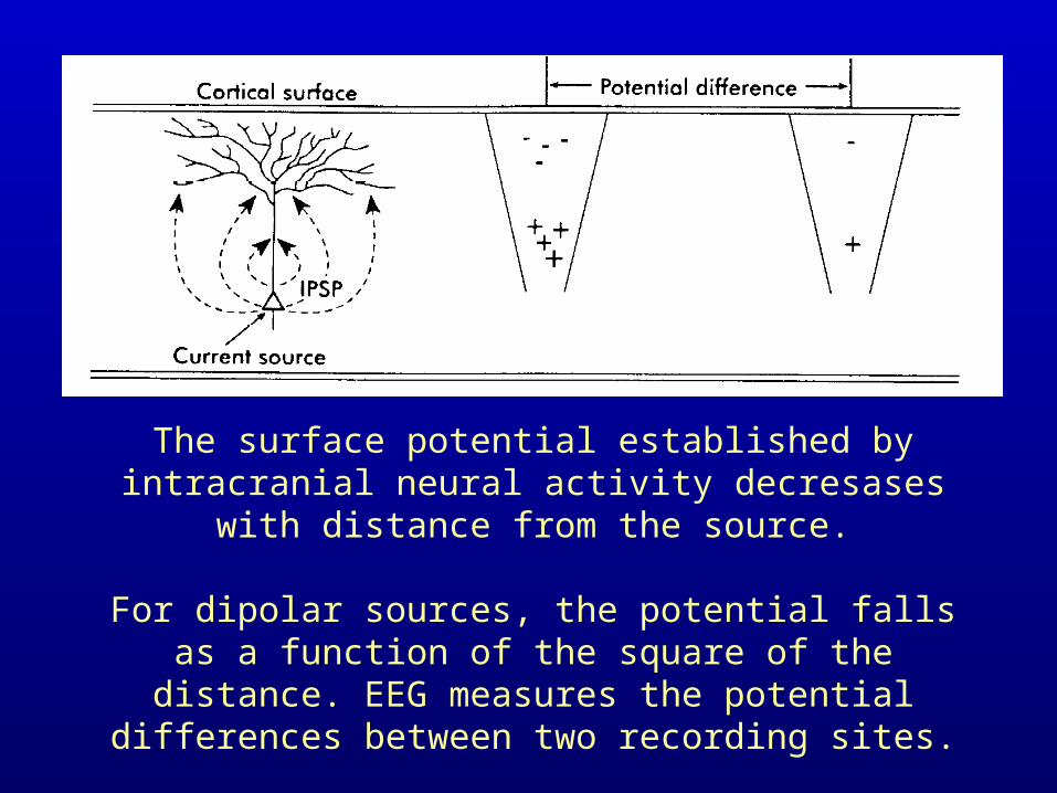
The surface potential established by intracranial neural activity decresases with distance from the source.
For dipolar sources, the potential falls as a function of the square of the distance. EEG measures the potential
differences between two recording sites.

Action potentials are associated with a leading depolarization front and a trailing repolarizing front. The associated current configuration is quadrupolar, and at a
distance, the electrical field generated by each of the opposing current components mostly cancel each other.

Introduction EEG
EEG measures the potential difference on the skin surface due to the backflowing current at the surface.
++-

Introduction to MEG
• MEG records the gradient of the Magnetic Induction
ddx
B x t ( , )
The Magnetic Induction results from electrical currents

Introduction to MEG
Electrical current in the brain•spatial components
•transmembrane current•intra-cellulair current•extra-cellulair current
•temporal components•activation of synapses•spiking activity

EEG

EEG “without” skull

MEG “without” skull

MEG

How the EEG is recorded
• Bipolar or Monopolar derivation– a-b; b-c; c-d; d-e; etc.
– a-ref; b-ref; c-ref; d-ref; etc.
• Clinical routine: 10-20 system with 21 electrodes
• Recording problems:– Skin resistance & skin capacitance
– Mechanical
– DC recording
– noise from bad grounding

Modern EEGequipment
• up to 256 leads
• small and portable
• fully digitized
• battery operated
• cheap

Temporal aspects of MEG & EEG
• Normal power spectrum of ongoing activity shows 1/f behaviour plus alpha band activity
• Changes in ongoing signals can be induced by sensory stimulation: ERF: Event Related Fields, ERP: Event Related Potentials
• ERF and ERP are significantly smaller than ongoing signals. Maximal SNR ~ 1:5; thus averaging necessary

Event-related
potentials need
averaging.
Each component
in the waveform is thought to
have a characteristic neural origin.
Oscillatory dynamics
• Event related desynchronization of the alpha, mu and tau rhythms occurs upon events that require processing of many stimulus aspects or recall (Pfurtscheller, 89)
• Event related synchronization occurs in the gamma band upon similar “global” stimuli (Freeman, 76)
• Many pathological conditions are associated with increased ongoing, mostly slow, rhythmical activity
• During maturation oscillatory activity increases in frequency and decreases in amplitude
• Sleep stages are characterized by different rhythms

Oscillatory Rhythms in EEG/MEG
• Alpha EEG/MEG 8-13 Hz Occipital• Beta EEG/MEG 18-30 Hz• Gamma EEG/MEG 40+ Hz• Delta MEG/EEG 0-4 Hz• Theta EEG/MEG 4-8 Hz• Mu MEG/EEG 10-14 Hz Central• Tau MEG 12-16 Hz Frontal

The mu rhythm is maximal in a central-frontal derivation. It is
unreactive to eye opening and closing, but
highly reactive to movements, such as
making a fist.

Repetitive triphasic complexes are a characteristic finding in the EEG of patients with progressive Creutzman-Jacob disease.

Brain topology mapping:color coding of potential field

Introduction to MEG
• MEG has better spatial resolution than EEG
• MEG is reference free
• MEG has much better temporal resolution than fMRI, PET or SPECT
but:
magnetic signals from the brain are very small and MEG systems therefore difficult and expensive

Every current induces a
magnetic field

Time-varying neuromagnetic signals
induce an electrical current in the wire loops of the
detection coil.
For the axial gradiometer the upper and lower coil
are wound in the opposite direction. The amount of
current induced in the system therefore reflects the spatial gradient of the
neuromagnetic field.

Signal Amplitudes ofBiomagnetism and environmental
(in Tesla)
• 1 nT lung particles• 100 pT heart• 50 pT muscle• 20 pT foetal heart• 10 pT MRG• 1 pT alpha rhythm• 20-100 fT Evoked
Fields
• 100 T Earth Field• 10T• 1T• 10-1000 nT Urban Noise• 10 nT VW beagle at 50m• 1 nT• 100 pT screwdriver at 5m• 10 pT• 1 pT CMOS IC op 2m• 100 fT diode op 1m • 10 fT• 1 fT noise-level Squids

Noise sources
• electromotors• elevators• power supplies• cars• trains• MRI• mechanical• stimulus artefacts
• ECG• respiration• eye movements• “ongoing brain signal”
metal implantsdental fillingsbra’spiercingstattooshair dyes

Noise elimination
• Shielding (MSR) 100.000x
• Gradient formation (hardware or software) 1000x
• Active compensation 0.1x-1000x
• Adaptive filtering 100x
Problems: costsintroduction of high frequency noisedecreased sensitivity

How is the MEG recorded?
• changed flux through pick-up coil => current through input-coil
• induction => flux over SQUID
• Josephson junctions yield a potential
• This potential is cancelled by feedback current through the feedback coil
• The amplitude of the feedback signal is a measure of the flux at the pick-up coil.

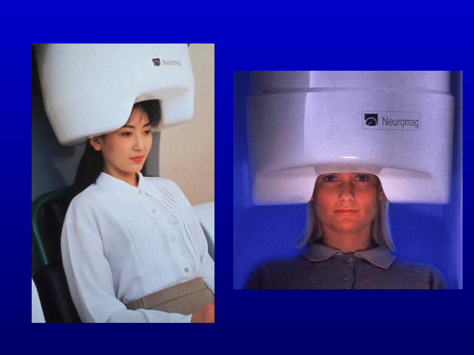
The 150 channel MEG system at the KNAW MEG/EEG Center at the Free
University of Amsterdam
(dr. B. van Dijk, director)

Present System Hardware
• 150 radial gradiometers; 5 cm baseline
• 29 field and gradient reference channels
• 72 EEG channels
• 16 ADC channels
• 32 digital channels (I/O)


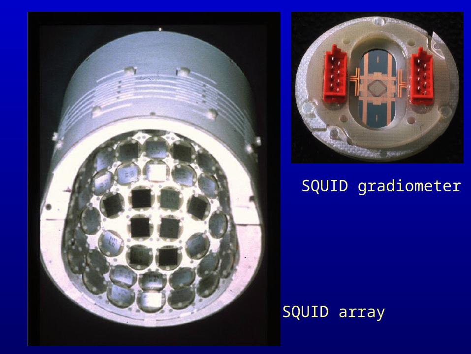
SQUID gradiometer
SQUID array

A Faraday shielding cageis necessary to preventinterferences with externalSources.


Analysis EEG & MEG“Can we calculate the current sources in the brain from the measurements?”
• Forward solution– given the electrical current density– given the form, susceptibility and conductance
of the different tissues of the head
• Calculate the magnetic induction or the electric field at the location of the sensors.

Analysis EEG & MEG
• Inverse solution:– given the magnetic induction/electric potential– assume a volume conductivity model
• calculate the electrical current density

Fysical basis EEG & MEG
• Macroscopic Maxwell equations (linear; relations between D,H,B,E,j,s)
• Material properties (conductivity, polarizability, susceptibility)
• Quasi static approximation (time derivatives can be neglected)
• Assume that material properties are homogeneous at the location of the sources

• Two decoupled expressions
for the electrical potential:
Fysical basis EEG & MEG
and for the magnetic induction:
• There are both in the electrical as in the magnetic casesources that do NOT lead to a macroscopic field.
So there exist no unique inverse solutions.
. . ji
1 1 B 1 ji

Analysis of EEG & MEG
• “SILENT SOURCES”: Many electric current density distributions yield a magnetic induction field or a potential field that is identically zero outside the scalp.
• As a result the inverse problem is only solvable by making assumptions about both volume conductor and electric current sources

• infinite medium
• sphere
• sphere shells
• revolution ellipsoïds, with shells
• “realistic” modelsboundary elementsfinite elements
Volume conductors
Ana
lytic
Num
eric
al
MR
I or
oth
er h
ead-
form
de
scri
ptio
n ne
cess
ary

stationary dipole co-registered to MR
Visualcolour reversal

Picture Naming vs. Picture Recognition

AbnormalLowFrequencyMagneticActivity
.25 s
2 pT
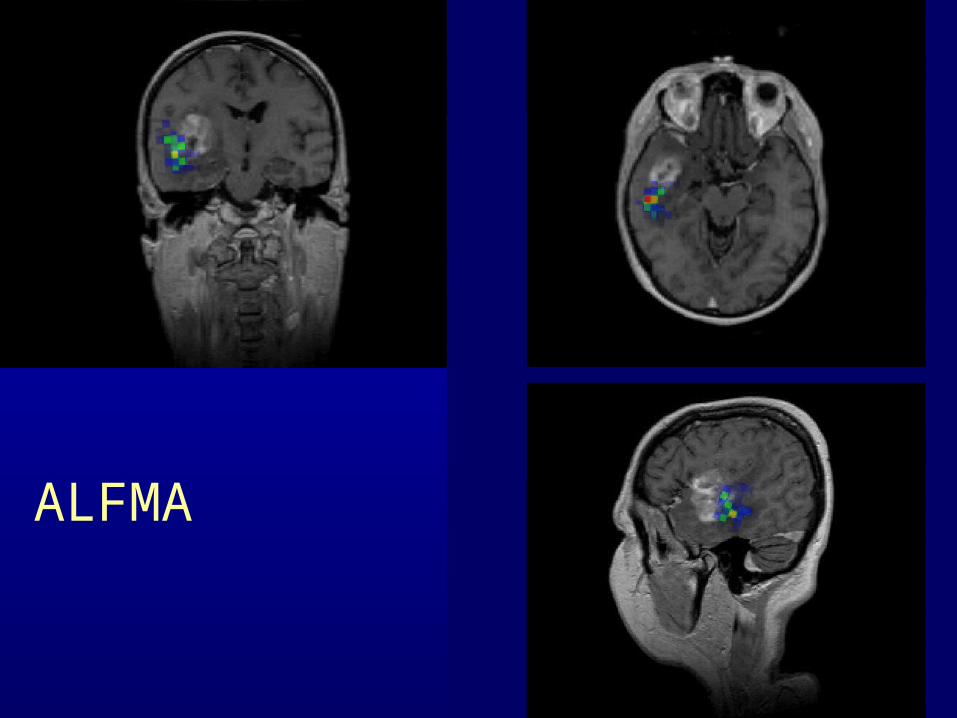
ALFMA

1 sec.
3 pT, 130 uV
EEG
LC
LT
LF
LP
LO
RC
RT
RF
RP
RO
Sleep spindles EEG and MEG
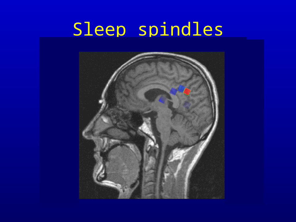
Sleep spindles