Embed Size (px)
Citation preview

Magforce SLS Linear Actuator
Read this manual before installing, operating
or maintaining this actuator. Failure to follow
safety precautions and instructions could
cause actuator failure and result in serious
injury, death or property damage.
Installation, operation and maintenance manual
ООО "Индастриал Партнер"
Авторизованный дистрибьютор SKF
www.skf.indpart.ru [email protected]
8(495)223-07-69
Техническая поддержка:
[email protected], 8(495)223-07-69

2
® SKF and Magnetic are registered trademarks of the SKF Group.
© SKF Group 2007.The contents of this publication are the copyright of the publisher and may not be reproduced (even extracts)unless prior written permission is granted.Every care has been taken to ensure the accuracy of the information contained in this publication but no liability can be accepted for any loss or damage whether direct, indirect or consequential arising out of the use of the information contained herein.
ООО "Индастриал Партнер"
Авторизованный дистрибьютор SKF
www.skf.indpart.ru [email protected]
8(495)223-07-69
Техническая поддержка:
[email protected], 8(495)223-07-69

3
1. Overview of linear actuators ................................................................................4 SLS (three phase current) ...................................................................................4
2. Safety .....................................................................................................................5 2.1 General safety instructions ..........................................................................5 2.2 Use in accordance with the regulations .....................................................5 2.3 Identifi cation of dangers ...............................................................................5 2.4 Safety at work ................................................................................................6 2.5 Technical progress .........................................................................................6 2.6 Guarantee .......................................................................................................6
3. Assembly and installation of the linear actuator .............................................7
4. Electrical connections ..........................................................................................8 4.1 Electrical connections for linear actuator ..................................................8 4.2 Electrical connection of linear actuators with stroke limit switching .....9 4.3 Electrical connection of potentiometer ......................................................10 4.4 Setting the end stroke limit switch (optional) ...........................................10 4.5 Setting the potentiometer (optional) ..........................................................11
5. Operation / starting up ........................................................................................11
6. Electrical and mechanical data ............................................................................12
7. Care and maintenance .........................................................................................13
8. Troubleshooting and fault rectifi cation ..............................................................13
9. Technical support ..................................................................................................13
10. Replacement parts and accessories ..................................................................13
11. End of life disposal ...............................................................................................13
Table of Contents
iООО "Индастриал Партнер"
Авторизованный дистрибьютор SKF
www.skf.indpart.ru [email protected]
8(495)223-07-69
Техническая поддержка:
[email protected], 8(495)223-07-69

4
1. Overview linear actuators
SLS (three phase current)
Fig. 1 Overview linear actuator Magforce
1. Motor unit with electrical brake (three-phase current)2. Connecting terminal case3. Rear trunion4. Housing5. Protection tube6. Push tube7. Fork head
1
6
73
ООО "Индастриал Партнер"
Авторизованный дистрибьютор SKF
www.skf.indpart.ru [email protected]
8(495)223-07-69
Техническая поддержка:
[email protected], 8(495)223-07-69

5
2.1 General safety instructions
Magforce linear actuators have been designed, built and inspected for safe operation inaccordance with state-of-the-art technology the standards (Machine Directive 89/392EWG, Low Voltage Directive 73/23 EWG and EMV Directive 897 336 EWG) and have left the factory in a perfect and safe state. Despite this, the drive can be dangerous to persons and objects if they are not fi tted and operated correctly. Therefore this operating manual must be read in detail and understood and the safety instructions must be taken note of. In the case of incorrect use and for incorrect purposes, the manufacturer rejects any kind of liability and guarantee.The linear actuators described in Chapter 1 are machine parts in terms of the MachineDirective. They are only to be installed in machines and systems by specialist companies and institutions taking into account the valid guidelines and statutory regulations.Especially the following directives and the resulting laws and standards must be takeninto consideration: 89/ 392 EWG EU machine directive 72/ 23 EWG EU low voltage directive 897 336 EWG EU-EMV guidelineDepending on the use of the machine or system into which the linear drive is to beinstalled, additional product or product group specifi c guidelines and standards mayapply. It is the machine or system manufacturer who is responsible for ensuring thatthese guidelines and standards are complied with. Linear actuators may not be operated before all requirements specifi ed in the EU machine directives regarding safety and health have been fulfi lled.In terms of EMV guidelines, linear actuators are classifi ed as supplied parts for the exclu-sive use and processing by specialist companies. The measures required to comply with the MEV Safety regulations must be taken by the manufacturer of the end product taking into consideration the fi tting conditions, wiring, control and switching and must be checked in accordance with its use.
2.2 Use in accordance with the regulations
Magforce linear actuators are only to be used for lifting purposes. Every other type of use is not permitted. Reconstruction and changes to the linear drives or the electrical instal-lation is not permitted. Only original replacement parts and accessories from SKF may be used.
2.3 Identifi cation of dangers
Throughout the operating manual, possible dangers and information are identifi ed by the following symbols:
Warning!
This symbol identifi es actions and conditions which can present danger to life and limb of persons. Read the instructions carefully.
Attention!
This symbol identifi es all actions and conditions which can cause damage to objects. Read the instructions carefully.
Information!
This symbol identifi es factual and useful information for the user.
2. Safety
ООО "Индастриал Партнер"
Авторизованный дистрибьютор SKF
www.skf.indpart.ru [email protected]
8(495)223-07-69
Техническая поддержка:
[email protected], 8(495)223-07-69

6
2.4 Safety at work
n Depending on the location of where the linear actuator will be used, protective devices must be installed to protect people from crush injuries. Please read the relevant insurance liability and product specifi c regulations.n If this actuator is used in lifting gear or in applications which might endanger people, please contact SKF. In these cases, special safety nuts or secured fork heads which are available as an option must be used.n If the linear actuator is in operation, people or objects must not be positioned in the vicinity of the stroke area of the linear actuator.n Electrical connections at the client’s site must be designed so that in the case of a power failure and subsequent supply of power, the actuator cannot start up again.n Assembly and connection lines as well as technical data (load limits, operating times, ...) must be adhered to precisely in all aspect for the linear drives. Changes must be agreed with SKF beforehand.n Without additional cooling measures, the housing of the linear actuator can reach a temperature of 130 °C. If there is a danger of people or infl ammable objects coming into contact with the housing, a touch guard must be fi tted.n The inner limits must not be used as stroke limits. This can destroy the actuator. The actuator is not always self-locking. Static loads resting on the actuator can cause the actuator to move.n Connection, wiring etc. may only be performed by specialist electricians or trained personnel taking into account the applicable standards and safety regulations.n Before opening the device (connection case), the mains supply must be disconnected.n No technical changes may be made to the actuator.
2.5 Technical progress
The manufacturer reserves the right to adapt technical data to the progress in technology without making any special announcements. SKF will gladly provide information regarding possible changes and extensions to the operating manual and whether they are up to date.
2.6 Guarantee
Assuming that the operating conditions have been adhered to and no prohibited changes have been made to the interior of the device and the devices show no mechanical damage, the manufacturer grants a guarantee of 1 year after delivery on all mechanical and electri-cal components.
The instructions regarding safety at work must be taken into account.
ООО "Индастриал Партнер"
Авторизованный дистрибьютор SKF
www.skf.indpart.ru [email protected]
8(495)223-07-69
Техническая поддержка:
[email protected], 8(495)223-07-69

7
The linear actuator is fi tted to the rear front and rear attachement points. Rotation of the push tube during operation is not permitted. The load to be moved may only act centrally on the push tube, lateral forces must be avoided. The actuator can be mounted in any position, but it must not be tilted.Fixing regulations: Use fi xing bolts with a shear strength of at least 1.2 times the nominal force of the drive.
WARNING!The load to be moved must always act centrally on the connecting rod. Forces acting from the side must be avoided. When using in areas which could endanger people, a special securing nut and se-cured fork heads must be used in order to prevent the load moving in the case of overloading and nut breaking (see also Chapter 2.4 Safety at work). This must be taken into consideration during installa-tion.
3. Assembly and installation of the linear actuator
ООО "Индастриал Партнер"
Авторизованный дистрибьютор SKF
www.skf.indpart.ru [email protected]
8(495)223-07-69
Техническая поддержка:
[email protected], 8(495)223-07-69

8
4.1 Electrical connections for linear actuators
The motors must be connected in accordance with Fig. 2. The direction of rotation isreversed by polarity reversal via relays or push buttons.Direct polarity reversal must be avoided due to the inertia force and to protect the switch-ing elements.The key or switch must return to the zero position automatically if the appropriate operat-ing element has been enabled. At the stroke limits, the motor must only meet withresistance briefl y before cutting out. Otherwise the use of stroke limit switches is neces-sary.Stroke limit switching is available as an option.
WARNING!The installation must be performed by trained electricians. Before installation, the mains supply to the devices must be disconnected!
Before connecting, please note the type designation SLS and the appropriate connecting information
(see rating plate).
The electrical cables must be positioned such that they cannot be damaged by crushing, bending or tension. The cable entrance must be checked for tightness.
4. Electrical connection
40050
VHz
L1L2L3NPE
K1K2
K1K2
K2K1
549x000105
W1
W2V2
V1 U1
U2
Fig. 2 Connection diagrams for linear actuator
ООО "Индастриал Партнер"
Авторизованный дистрибьютор SKF
www.skf.indpart.ru [email protected]
8(495)223-07-69
Техническая поддержка:
[email protected], 8(495)223-07-69
9
4.2 Electrical connection of linear actuators with stroke limit switching
If the linear drive is equipped with end stroke limit switches, the drive must beconnected in accordance with Fig. 3.After the electrical connections have been made, it is necessary to see whether thedirection of rotation (polarity, phase) of the motor is correct by briefl y switching themotor on. If the direction of rotation is not correct, there is a danger that the strokelimits switches will be exceeded and therefore damaged.
WARNINGThe installation must be performed by trained electricians. Before installation, the mains supply to the devices must be disconnected!
Before connecting, please note the type designation SLS and the appropriate connecting information
(see rating plate).
The electrical cables must be positioned such that they cannot be damaged by crushing, bending or tension. The cable entrance must be checked for tightness.
40050
VHz
L1L2L3NPE
K1K2
K1K2
K2K1
1 2 3 4 5 6
limit switch549e000108
W1 V1 U1V2
U2 W2
Fig. 3: Connecting diagrams for linear actuators with end stroke limit switches.
ООО "Индастриал Партнер"
Авторизованный дистрибьютор SKF
www.skf.indpart.ru [email protected]
8(495)223-07-69
Техническая поддержка:
[email protected], 8(495)223-07-69

10
2
2
3
3
1
1
customerevaluate
549e000110
1 2
549x000111
4.3 Electrical connection of potentiometer
If the linear actuator is equipped with a potentiometer, the potentiometer must be con-nected in accordance with Fig. 4. The motor is connected according to voltage rating as described in Chapter 4.1.The instructions
regarding safety at work must be taken into account.
4.4 Setting the end stroke limit switch (optional)
The optional stroke limit switches are fi tted to the housing of the drive. There are two openings in the cover through which the stroke limit switches areadjusted using an Allan key. The openings must be closed after adjustment. The strokelimit is adjusted by positioning the two stroke limit switches on the respectivespindle (see Fig. 5). The push tube is secured to the rod housing with adhesive tape.If the push tube is rotated by hand, the setting of the lower stroke limit is not longercorrect.The stroke limit switches have been set to allow the greatest possible stroke (= 1...2 mm before the limit) at the factory before delivery.Procedure:Fit the cover of the end stroke limit switches once you have performed all electricalinstallations (see Chapter ”Electrical connections”) and have understood andchecked the mechanical function of the limit switches. Remember that the connectingterminals carry voltage!Then make sure that the motor is turning in the correct direction; if necessarychange phase sequence/polarity.Move the actuator to the desired lower limit.Now turn the stroke limit switch for the lower limit against the control cam sothat it connects.Now proceed in the same manner for the upper limit.Move the linear actuator up and down a number of times and if necessary make fi neadjustments
ATTENTION!If the stroke limit switches have beenset at the factory, the push tube maynot be rotated as otherwise the set-ting of the stroke limit switch position is no longer cor-rect.
WARNING!Danger of electric shock! The instal-lation work must be performed by trained electricians.Close the casing before you adjust the stroke limit switch. Terminalscarry voltage.
Fig. 4: Connecting the potentiometer
Fig. 5: Stroke limit switch
ООО "Индастриал Партнер"
Авторизованный дистрибьютор SKF
www.skf.indpart.ru [email protected]
8(495)223-07-69
Техническая поддержка:
[email protected], 8(495)223-07-69
11
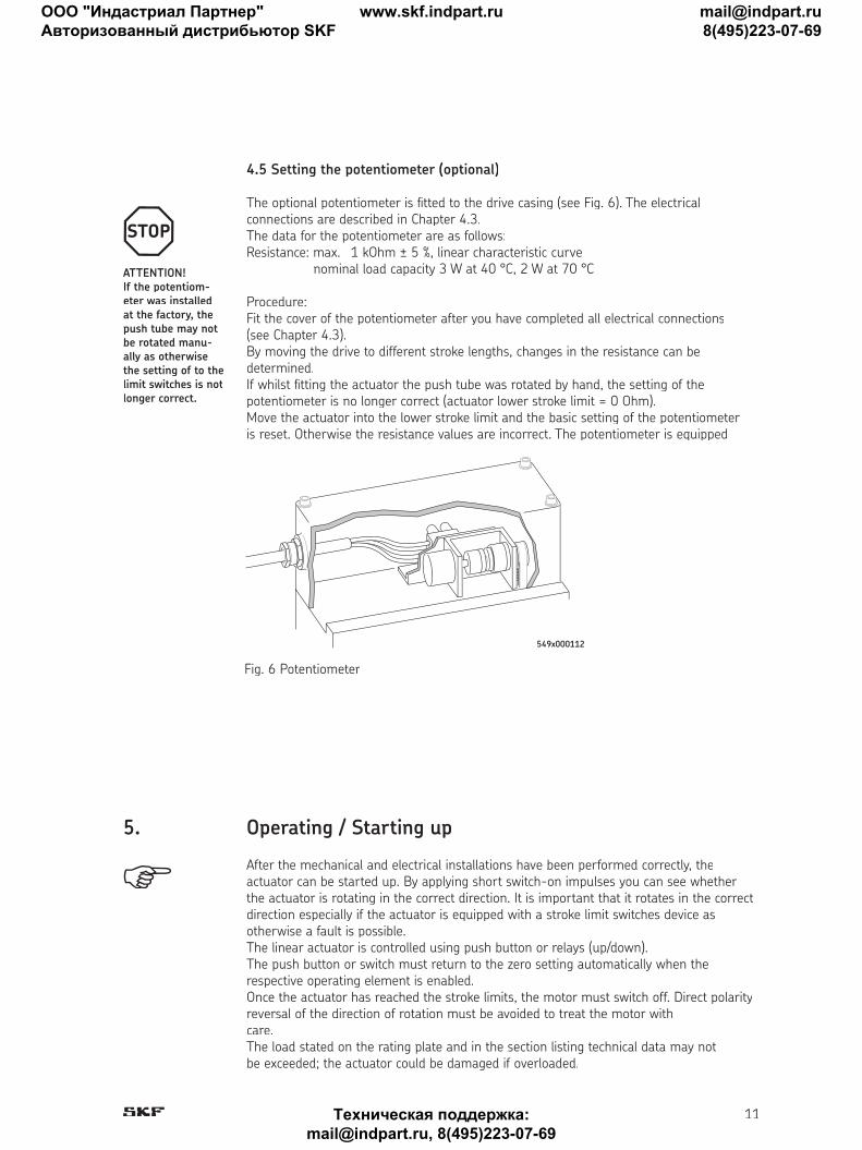
4.5 Setting the potentiometer (optional)
The optional potentiometer is fi tted to the drive casing (see Fig. 6). The electricalconnections are described in Chapter 4.3.The data for the potentiometer are as follows:Resistance: max. 1 kOhm ± 5 %, linear characteristic curve nominal load capacity 3 W at 40 °C, 2 W at 70 °C
Procedure:Fit the cover of the potentiometer after you have completed all electrical connections(see Chapter 4.3).By moving the drive to different stroke lengths, changes in the resistance can bedetermined.If whilst fi tting the actuator the push tube was rotated by hand, the setting of thepotentiometer is no longer correct (actuator lower stroke limit = 0 Ohm).Move the actuator into the lower stroke limit and the basic setting of the potentiometeris reset. Otherwise the resistance values are incorrect. The potentiometer is equipped
ATTENTION!If the potentiom-eter was installed at the factory, the push tube may not be rotated manu-ally as otherwise the setting of to the limit switches is not longer correct.
After the mechanical and electrical installations have been performed correctly, theactuator can be started up. By applying short switch-on impulses you can see whetherthe actuator is rotating in the correct direction. It is important that it rotates in the correctdirection especially if the actuator is equipped with a stroke limit switches device asotherwise a fault is possible.The linear actuator is controlled using push button or relays (up/down).The push button or switch must return to the zero setting automatically when therespective operating element is enabled.Once the actuator has reached the stroke limits, the motor must switch off. Direct polarityreversal of the direction of rotation must be avoided to treat the motor withcare.The load stated on the rating plate and in the section listing technical data may notbe exceeded; the actuator could be damaged if overloaded.
5. Operating / Starting up
Fig. 6 Potentiometer
549x000112
ООО "Индастриал Партнер"
Авторизованный дистрибьютор SKF
www.skf.indpart.ru [email protected]
8(495)223-07-69
Техническая поддержка:
[email protected], 8(495)223-07-69

12
Type SLS (three-phase current) SLS 18006 SLS 34013 SLS 50020 SLS 50028 SLS 50050
Pressure / tensile strength kN 18 34 50 50 50Electrical brake kN yes yes yes yes yes(actuator self-braking)Static load kN 60 60 60 60 60Thrust speed mm/s 74 36 23 16 9Stroke length mm 100 to 700 100 to 700 100 to 700 100 to 700 100 to 700Mains supply V/50 Hz 3 x 400 3 x 400 3 x 400 3 x 400 3 x 400Power consumption W 3 000 3 000 3 000 2 000 1 900Current consumption A 3,9 3,9 3,9 3,5 3,0Operating time (SD 10 min.) % 10 10 10 10 10Ambient temperature °C -10 to +40 -10 to +40 -10 to +40 -10 to +40 -10 to +40Safety class/isolation class I/B I/B I/B I/B I/Blevel of protection IP 54 54 54 54 54Weight kg 48 48 48 48 48
† 200
† 30
† 8
0
† 1
10
† 30
† 157
65
238
381
308
60
Stroke + 380/+2
Stroke + 446/+2
100
25
45
228 90
191
8062
6. Electrical and mechanical data
ООО "Индастриал Партнер"
Авторизованный дистрибьютор SKF
www.skf.indpart.ru [email protected]
8(495)223-07-69
Техническая поддержка:
[email protected], 8(495)223-07-69
13
The linear actuator is equipped with a special nut and suffi cient lubrication reserve andtherefore requires no maintenance.The service life of the actuator depends on the operating location and the operatingperiod.The push tube must be cleaned and lubricated from time to time. Defective motorsmust be repaired by SKF or by one of their authorised dealers.For customer specifi c applications where the path-force-cycle ratios and environmentalinfl uences are known, the maintenance intervals are specifi ed in the orderconfi rmation or in a separate document.
7. Maintenance and care
Repairs must be performed by SKF or by one of their authorised dealers.Therefore please return a defective drive.However, fi rst check all electrical connections and mechanical components for possibledefects.If the actuator nut is broken, the actuator can continue to work under light loads onthe safety nut (optional). A low power output and high power consumption point towards this type of damage. Regular operation is not permissible in this case. The device must berepaired at the manufacturer.
8. Troubleshooting and rectifi cation of faults
If faults occur during the operation or guarantee period which cannot be rectifi ed bytrained electricians, please contact our internal experts.
9. Technical support
Accessory
Extended shaft
Customer specifi c drives are defi ned on the order confi rmation.
10. Replacement parts and accessories
ООО "Индастриал Партнер"
Авторизованный дистрибьютор SKF
www.skf.indpart.ru [email protected]
8(495)223-07-69
Техническая поддержка:
[email protected], 8(495)223-07-69
14
Your new set contains materials which can be recycled and reused. Specialized companiescan recycle your product to increase the amount of reusable materials and minimize the amount of materials to be disposed of.Please inform yourself on local regulations on disposal of your old set.
Manufacturer’s address
Magnetic Elektromotoren AGOristalstrasse 97CH-4410 LiestalTel. + 61 / 925 41 11Fax. + 61 / 921 37 04e-mail: [email protected]
11 End of life disposal
ООО "Индастриал Партнер"
Авторизованный дистрибьютор SKF
www.skf.indpart.ru [email protected]
8(495)223-07-69
Техническая поддержка:
[email protected], 8(495)223-07-69