Embed Size (px)
Citation preview

FPC-07
Fire Pump Controller
Installation/ Operation Manual
LT0456 Issue 1.1

FPC-07 Installation & Operation Manual Document: LT0456
Page ii 9 August 2011 Issue 1.1
Manufacturer’s Details
Standards Compliance NZS 4541:2007, NZS 4541:2003,
AS/NZS CISPR 22:2006 (EMC), AS/NZS 60950:2003 (Electrical Safety)
Manufacturer The Vigilant FPC-07 Fire Pump Controller is manufactured by: Tyco Fire Protection Products 17 Mary Muller Drive Christchurch 8022 New Zealand
Copyright and Trademark Information
2011 Tyco Fire Protection Products, Christchurch, New Zealand.
All specifications and other information shown were current as of document revision date, and are subject to change without notice.
Tyco and Vigilant are trademarks of Tyco International Ltd. or its affiliates in the U.S. and/or other countries. No part of this document may be reproduced or transmitted in any form or by any means, electronic or mechanical, for any purpose, without the express written consent of Tyco Safety Products.
Document Document Number : Issue:
LT0456 1.1 9 August 2011
Firmware Revision
1.1
Amendments 1.0 Original. 1.1 New charger spare parts added.

Document: LT0456 FPC-07 Installation & Operation Manual
Issue 1.1 9 August 2011 Page iii
Table of Contents
Chapter 1 Introduction ................................................................................................ 1-1
Using this Manual ____________________________________________ 1-1
Associated Documentation _____________________________________ 1-1
Chapter 2 System Description ................................................................................... 2-1
Overview ___________________________________________________ 2-1
Display Panel _______________________________________________ 2-1
Control Keys ________________________________________________ 2-1
Chapter 3 Specifications ............................................................................................ 3-1
Physical ___________________________________________________ 3-1
Power Supply _______________________________________________ 3-1
Environmental _______________________________________________ 3-1
Battery Chargers ____________________________________________ 3-1
Engine Sensor Types _________________________________________ 3-1
Engine Start Outputs _________________________________________ 3-1
Other Outputs _______________________________________________ 3-1
Standards Compliance ________________________________________ 3-2
System Normal ______________________________________________ 3-1
Chapter 4 Interpreting the Displays .......................................................................... 4-1
Status Display _______________________________________________ 4-2
Engine Display ______________________________________________ 4-3
Pressure Switches ___________________________________________ 4-4
Battery A Battery B ___________________________________________ 4-5
Chapter 5 Using the Control Panel ............................................................................ 5-1
Testing the Display Panel ______________________________________ 5-1
Silencing Alarms _____________________________________________ 5-1
Reading Battery Charge Current ________________________________ 5-1
Reading Battery Float Voltage __________________________________ 5-1
Reading Battery Voltage _______________________________________ 5-1
Reading Engine Temperature ___________________________________ 5-2
Reading Engine Oil Pressure ___________________________________ 5-2
Isolating Pressure Switches ____________________________________ 5-2
Manually Starting the Pump ____________________________________ 5-2
Chapter 6 Alarm Displays ........................................................................................... 6-1
Alarm Conditions ____________________________________________ 6-1
Error Codes ________________________________________________ 6-3
Chapter 7 Installation Information ............................................................................. 7-1
Cabinet Mounting on a Wall ____________________________________ 7-1
Cabinet Mounting Free-standing ________________________________ 7-1
Pressure Switch Wiring ________________________________________ 7-2
Pressure Switch Adjustment ____________________________________ 7-3
Pump Set Wiring _____________________________________________ 7-4
Spare Parts and Drawings _____________________________________ 7-4

FPC-07 Installation & Operation Manual Document: LT0456
Page iv 9 August 2011 Issue 1.1

Document: LT0456 FPC-07 Installation & Operation Manual
Issue 1.1 9 August 2011 Page v
PROGRAMMED CONTROLLER SETTINGS FOR THIS INSTALLATION The particular configuration values for this installation should be recorded here for reference in case of controller CIRCUIT BOARD replacement and the need to re-program a replacement.
Setting Name Value Units
Number of Pressure Switches -
Recycling Delay seconds
Crank Fail Time seconds
Temperature sender type -
Max. engine temperature C
Min. engine temperature C
Pressure sender type -
Min. oil pressure kPa
Max. battery voltage volts
Min. battery voltage volts
No of pulses per engine rev. -
Engine crank speed threshold rpm
Engine run speed threshold rpm
Engine overspeed limit rpm
Off normal battery voltage Yes / No -
Off normal engine readings Yes / No -
Off normal sensor connections Yes / No -
Off normal charger fail Yes / No -
Off normal start fail Yes / No -
Installation Name: ................................................ Date Installed: ................................................


Document: LT0456 FPC-07 Installation & Operation Manual
Issue 1.1 9 August 2011 Page 1-1
This manual contains information for personnel engaged in the installation, commissioning, and routine maintenance and testing of a diesel pump set containing the Vigilant FPC-07 Fire Pump Controller unit. The manual has the following chapters: 1. Introduction - an introduction to this manual. 2. System Description - a brief description of the FPC-07. 3. Specifications - a summary of FPC-07 specifications. 4. Interpreting the Displays - how to read the display panel. 5. Using the Control Panel - what the controls on the panel do. 6. Alarm Displays - what the alarm displays mean. 7. Installation Information - Mounting and wiring the controller.
FPC-07 Technical Manual - provides complete details on planning, commissioning and configuring the FPC-07, as well as technical descriptions and schematics of the internal electronics. The ordering code of the FPC-07 Technical Manual is LT0457.
Chapter 1 Introduction
Using this Manual
Associated Documentation


Document: LT0456 FPC-07 Installation & Operation Manual
Issue 1.1 9 August 2011 Page 2-1
The Vigilant FPC-07 Fire Pump Controller is an intelligent microcontroller-based battery charger and control unit intended for use with diesel engine pump sets. It provides displays of engine and battery condition, monitors up to six pressure switch circuits, and will attempt to automatically start the engine when any pressure switch operates. It will generate alarm signals in the event of abnormal engine or battery conditions.
The FPC-07 has five electronic digital displays, associated status indicators, and two mechanical gauges. The electronic displays show the state of the batteries, pump engine and pressure switches, while the mechanical gauges show the suction and delivery pressures from the pump.
Adjacent to the electronic displays are ten pushbutton controls, which allow the operator to test the displays, silence alarms, check battery condition, and manually start the pump set. Each key is labelled in white according to its functions. Some keys have alternate functions in programming mode; these are the blue legends under the key. This manual does not deal with programming the controller; refer to the Technical Manual. With the exception of the Manual Start buttons, all keys produce a brief "beep" from the internal buzzer when pressed. The use of the controls is detailed in Section 5.
Chapter 2 System Description
Overview
Display Panel
Control Keys


Document: LT0456 FPC-07 Installation & Operation Manual
Issue 1.1 9 August 2011 Page 3-1
Dimensions 800H x 500W x 200D (including gauge housing) Weight 20kg Cabinet Material 1.6mm Zintec Finish Red ripple powdercoat Mounting Holes Four points, up to M12 fasteners.
See drawing 1941-42 for dimensions.
Single phase 230V 1A AC, permanently connected to internal switched outlets. Standby power taken from pump set engine batteries.
Ambient Temperature: -10C to +55C Humidity: 0-95% RH (non-condensing) Cabinet Rating IP54 (nominal, not formally certified)
Dual constant-voltage type, either 12V or 24V. Independently capable of supplying at least 6A charge current (suitable for engine batteries up to 120Ah). Tolerant of short circuit and/or reverse battery connection.
Proximity detector: NPN type, 12V type (for both 12V and 24V systems).
Autonics PR12-2DN, PR18-5DN, or PR18-8DN Compatible temperature senders: VDO type 320-002 Compatible oil pressure senders: VDO type 360-002
Two outputs, START A and START B, each switching the respective battery voltage. Each is one set of Normally-Open contacts rated at 5A, with suppression diodes across each contact set.
Pump Running: One set of voltage-free 1A changeover contacts plus
plus one output of switched 12V/24VDC, up to 2A resistive load. These outputs are operated whenever the engine is running. Maskable for up to 1 hour by pressing the SILENCE ALARMS button.
Chapter 3 Specifications
Physical
Power Supply
Environmental
Battery Chargers
Engine Sensor Types
Engine Start Outputs
Other Outputs

FPC-07 Installation & Operation Manual Document: LT0456
Page 3-2 9 August 2011 Issue 1.1
Off Normal: One set of voltage-free 1A changeover contacts plus
one output of switched 12V/24VDC, up to 2A resistive load. These outputs are operated whenever there are fault or off-normal conditions with the pumpset. The conditions contributing to this output may be configured on site. Maskable for up to 1 hour by pressing the SILENCE ALARMS button.
NZS 4541:2007 NZS 4541:2003 AS/NZS 60950:2003 AS/NZS CISPR22:2006
Standards Compliance

Document: LT0456 FPC-07 Installation & Operation Manual
Issue 1.1 9 August 2011 Page 4-1
Under normal circumstances (pump not running, AC mains on, no pressure switches operated), the display panel will be as follows: Status Area: Ready to Start on. Engine: Engine Speed reading zero.
Engine Run Time reading accumulated run time. Temperature/Oil Pressure reading a temperature,
with C on. Pressure Switches: All indicators off. Battery A & B: Volts indicators on, and display reading in the region
of 13-14V (for a 12V system) or 26-28V (for a 24V system). Both Charger On indicators on.
In the absence of any activity for the previous 15 minutes, the displays will dim to conserve power; if any key is pressed, or if the engine is active, the displays will brighten up again. In general, the displays will be steadily lit. Any flashing display indicates an alarm or abnormal condition. See section 6 for details.
System Normal
Chapter 4 Interpreting the Displays

FPC-07 Installation & Operation Manual Document: LT0456
Page 4-2 9 August 2011 Issue 1.1
The status indicators show the state of the engine starting process and alarm indicators. When lit the indicators have the following meaning:
Ready to Start:
The controller is ready to start the pump motor. To confirm that the controller is operating, this indicator "blinks" off at about 8 second intervals.
Start Initiated:
The controller is in the process of starting, or has started the motor. When flashing, this indicates that the initial attempt to start the motor failed.
Cranking Engine:
The starter motor relays are energised, either by the controller, or by pressing a Manual Start key.
Engine Running:
The engine has reached a predefined minimum running speed.
Alarms Silenced:
The external alarm contacts have been disabled by pressing SILENCE ALARMS.
Status Display

Document: LT0456 FPC-07 Installation & Operation Manual
Issue 1.1 9 August 2011 Page 4-3
The engine readings displays show the following engine conditions: Engine Speed: Shows the measured speed in rpm. Flashing
indicated overspeed. Engine Run Time: Displays the cumulative engine run time in hours and
minutes.
Temperature/ This is a dual mode display. The C or kPa Oil Pressure: indicators show which of engine temperature or
engine oil pressure is being displayed. Pressing the adjacent TEMP/OIL key toggles the display from one to the other. The display defaults to temperature after a period of time. Flashing indications denote faults as described in more detail in Chapter 6.
Engine Display

FPC-07 Installation & Operation Manual Document: LT0456
Page 4-4 9 August 2011 Issue 1.1
The pressure switch indicators show the status of the pressure switches. When lit, the indicators have the following meanings:
Activated: These show which pressure switches are operated.
Isolated: These show that the corresponding pressure switch has been isolated. Pressing ISOLATE will isolate all the currently-operated pressure switches. When each pressure switch is released, it will be automatically de-isolated after a short delay. If one of these indicators is flashing, it indicates a wiring fault for the corresponding pressure switch.
Pressure Switches

Document: LT0456 FPC-07 Installation & Operation Manual
Issue 1.1 9 August 2011 Page 4-5
There are two identical battery displays, one for each of the separate battery/charger combinations. Each value displayed is either battery voltage or charge current. The Volts or Amps indicators show which is being displayed. Pressing the VOLTS/AMPS key toggles between the different readings. The display defaults to voltage after a period of time. The Charger On indicator shows that there is input power to the respective battery charger, regardless of whether charge current is being delivered.
The voltage display normally shows battery voltage under charging conditions. Pressing and holding the BATT VOLTS key temporarily inhibits the charger and displays the off-charge battery voltage, which is a better indication of actual battery condition. The on-charge voltage or current is displayed again when the button is released. Flashing indications denote faults as described in more detail in Chapter 6.
Battery A Battery B


Document: LT0456 FPC-07 Installation & Operation Manual
Issue 1.1 9 August 2011 Page 5-1
Press and hold the LAMP TEST key. All indicators will light up, all digits will read "8"s, and all but 8 decimal points will light. The normal display resumes when LAMP TEST is released. The controller firmware version and error codes for any abnormal conditions will be displayed after 4 seconds while the LAMP TEST key is held – see Chapter 6 for more details.
All external alarm contacts can be disabled for 60 minutes by pressing SILENCE ALARMS. The Alarms Silenced indicator will be lit. During the last minute before re-enabling the alarms, the internal buzzer will beep at one second intervals as a warning. Pressing SILENCE ALARMS again resets the disabled period to 60 minutes. The alarms can be re-enabled by pressing and holding SILENCE ALARMS for two seconds. The Alarms Silenced indicator will go out.
If the Amps indicator is not on steadily, press the VOLTS/AMPS key once. The charge current in amps will be displayed.
If the Volts indicator is not on steadily, press the VOLTS/AMPS key once. The battery float voltage while on charge will be displayed.
Press and hold the BATT VOLTS key. The Charger On indicator will go out, and the Volts indicator will come on. The "off-charge" battery voltage will be displayed. The previous display will be restored when BATT VOLTS is released.
Chapter 5 Using the Control Panel
Testing the Display Panel
Silencing Alarms
Reading Battery Charge Current
Reading Battery Float Voltage
Reading Battery Voltage

FPC-07 Installation & Operation Manual Document: LT0456
Page 5-2 9 August 2011 Issue 1.1
If the C indicator is not on steadily, press the TEMP/OIL key once. The engine temperature will be displayed.
If the kPa indicator is not on steadily, press the TEMP/OIL key once. The engine oil pressure will be displayed.
The Activated indicators show which pressure switch(es) are operated. Pressing ISOLATE will isolate all the currently-operated pressure switches. When each pressure switch is released, it will be automatically de-isolated.
Pressing either the green BATT A or BATT B keys will directly operate the start relays and crank the engine, bypassing the controller logic. If the controller is running, the status indicators and engine display will show the state of the engine. These keys will still operate even if the controller has failed.
Reading Engine Temperature
Reading Engine Oil Pressure
Isolating Pressure Switches
Manually Starting the Pump

Document: LT0456 FPC-07 Installation & Operation Manual
Issue 1.1 9 August 2011 Page 6-1
Alarm conditions may be signalled by devices connected to the external Off-Normal alarm relay contacts. More detail is provided by the flashing of the part of the display associated with the alarm condition. The controller may have been configured so that some off-normal conditions will not cause an external alarm. Regardless of this, any abnormal condition will always cause some part of the display to flash. To see more information about an abnormal condition, press and hold the LAMP TEST/STATUS key. After a lamp test period of 3 seconds, and a brief display of the controller firmware version, the Engine Run Time display will show an error code in the format “Err” plus a 2-digit code number. Locate this code number in the Table 6-2 for more detail about the error or fault. If there are several abnormal conditions, their respective codes will be displayed sequentially for as long as the LAMP TEST/STATUS key is held pressed.
Table 6-1 - Indicator Flashing Interpretation
WHAT IS FLASHING? WHAT IT MEANS
Ready to Start (blinks off once every 8 seconds)
Controller is operating correctly - no action is required.
EITHER BATTERY DISPLAY (Amps indicator on steady)
The corresponding charger has failed. Check ac mains supply if both chargers have failed, or the corresponding charger if only one has failed. (CHARGER ON indicator will be off).
Amps INDICATOR
FLASHING "oC" IN BATTERY DISPLAYS (Volts indicator on steady)
The lead to that battery is broken or incorrectly connected. Check the battery connection.
FLASHING "SC" IN BATTERY DISPLAYS (Volts indicator on steady)
The battery is faulty or reverse-connected. Check the battery polarity and condition.
EITHER BATTERY DISPLAY (Volts indicator on steady)
The battery voltage is out of range (too high or low). Check the battery condition.
Volts INDICATOR The battery voltage is out of range range (too high or low). Press VOLTS/AMPS to read the voltage (this reading will be flashing). Check the battery condition.
Chapter 6 Alarm Displays
Alarm Conditions

FPC-07 Installation & Operation Manual Document: LT0456
Page 6-2 9 August 2011 Issue 1.1
WHAT IS FLASHING? WHAT IT MEANS
Temperature/Oil Pressure
(C indicator on steady)
The engine temperature is out of range (too high or too low). Check the engine cooling/heating system.
C INDICATOR The engine temperature is out of range. Press TEMP/OIL to read the actual temperature (display will be flashing). Check the engine cooling/heating system.
Temperature/Oil Pressure (kPa indicator on steady)
The oil pressure is too low while the engine is running. Check the engine lubrication system.
kPa INDICATOR The oil pressure is too low when engine is running. Press TEMP/OIL to read the actual pressure (display will be flashing). Check the engine lubrication system.
FLASHING "oC" IN Temperature/Oil Pressure
(C indicator on steady)
The lead to the temperature sender is broken, or a connector is not seated properly on the Controller circuit board.
FLASHING "SC" IN Temperature/Oil Pressure
(C indicator on steady)
The lead to the temperature sender is short circuited to earth.
FLASHING "oC" IN Temperature/Oil Pressure (kPa indicator on steady)
The lead to the oil pressure sender is broken, or a connector is not seated properly on the Controller circuit board.
Engine Speed The engine speed is too high.
FLASHING "oC" IN Engine Speed
The leads to the engine speed sensor are broken, or a connector is not seated properly on the Controller circuit board.
ANY PRESSURE SWITCH Isolated INDICATOR
The associated pressure switch cable is faulty. Check for a broken wire at the circuit board end, or in the pressure switch case.
Start Initiated The controller is attempting to start the engine, but without success. Isolate the pressure switches by pressing ISOLATE, and attempt a manual start.
Run Time Internal controller fault. Other displays may be giving false readings. If the fault is not obvious, obtain expert assistance.

Document: LT0456 FPC-07 Installation & Operation Manual
Issue 1.1 9 August 2011 Page 6-3
To see error codes, press and hold the LAMP TEST/STATUS key. After a lamp test period of 3 seconds, and a brief display of the controller firmware version, the Engine Run Time display will show an error code in the format “Err” plus a 2-digit code number. Locate this code number in the Table 6-2 for more detail about the error or fault. If there are several abnormal conditions, their respective codes will be displayed sequentially for as long as the LAMP TEST/STATUS key is held pressed.
Table 6-2 - Error Code Interpretation
Category Code Meaning
Battery 1 Battery A voltage is low
2 Battery A voltage is high
3 Battery A is disconnected
4 Battery A is short circuit or reverse connected
5 Battery B voltage is low
6 Battery B voltage is high
7 Battery B is disconnected
8 Battery B is short circuit or reverse connected
Charger 10 Charger A is off
11 Charger B is off
Pressure Switches
21 Pressure Switch 1 wiring is faulty
22 Pressure Switch 2 wiring is faulty
23 Pressure Switch 3 wiring is faulty
24 Pressure Switch 4 wiring is faulty
25 Pressure Switch 5 wiring is faulty
26 Pressure Switch 6 wiring is faulty
Engine 30 Engine start sequence is taking too long
31 Engine temperature too low
32 Engine temperature too high
33 Oil pressure too low
34 Engine speed too high
Engine Wiring
40 Temperature sender wiring open circuit
41 Temperature sender wiring short circuit
42 Oil pressure sender wiring open circuit
43 Remote Common wiring open circuit
44 Speed sensor wiring open circuit
45 Start contactor A wiring open circuit
46 Start contactor B wiring open circuit
Controller Internal
50 Stored programmed configuration faulty/store operation was not successful – default or volatile memory values being used
51 Internal start relay wiring fault
52 Supervision wiring open circuit
53 Current Sense wiring open circuit
55 Manual start wiring open circuit
60 Fuse fault on controller
62 Controller link DPE is not fitted – may cause error 50
63 Controller link FPE is fitted
64 Display board wiring fault Bus 1
65 Display board wiring fault Bus 2
Error Codes


Document: LT0456 FPC-07 Installation & Operation Manual
Issue 1.1 9 August 2011 Page 7-1
The FPC-07 cabinet is designed to be wall-mounted, with four fastening points. The upper mounting holes on the cabinet are slotted, allowing the cabinet to be hung on studs or bolts in the wall. The lower mounting holes are not slotted, to secure the cabinet in place. M10 or M12 mounting screws are recommended. Refer to presentation drawing 1941-42, which shows the important dimensions for locating the mounting points. Where wall mounting of the FPC-07 is not convenient, the cabinet can be mounted on a free-standing frame. Refer to drawing 1941-51 which shows two versions of a suitable mounting frame constructed from Unistrut channel and couplings.
Chapter 7 Installation Information
Cabinet Mounting on a Wall
Cabinet Mounting Free-standing
FPC-07 Installation & Operation Manual Document: LT0456
Page 7-2 9 August 2011 Issue 1.1
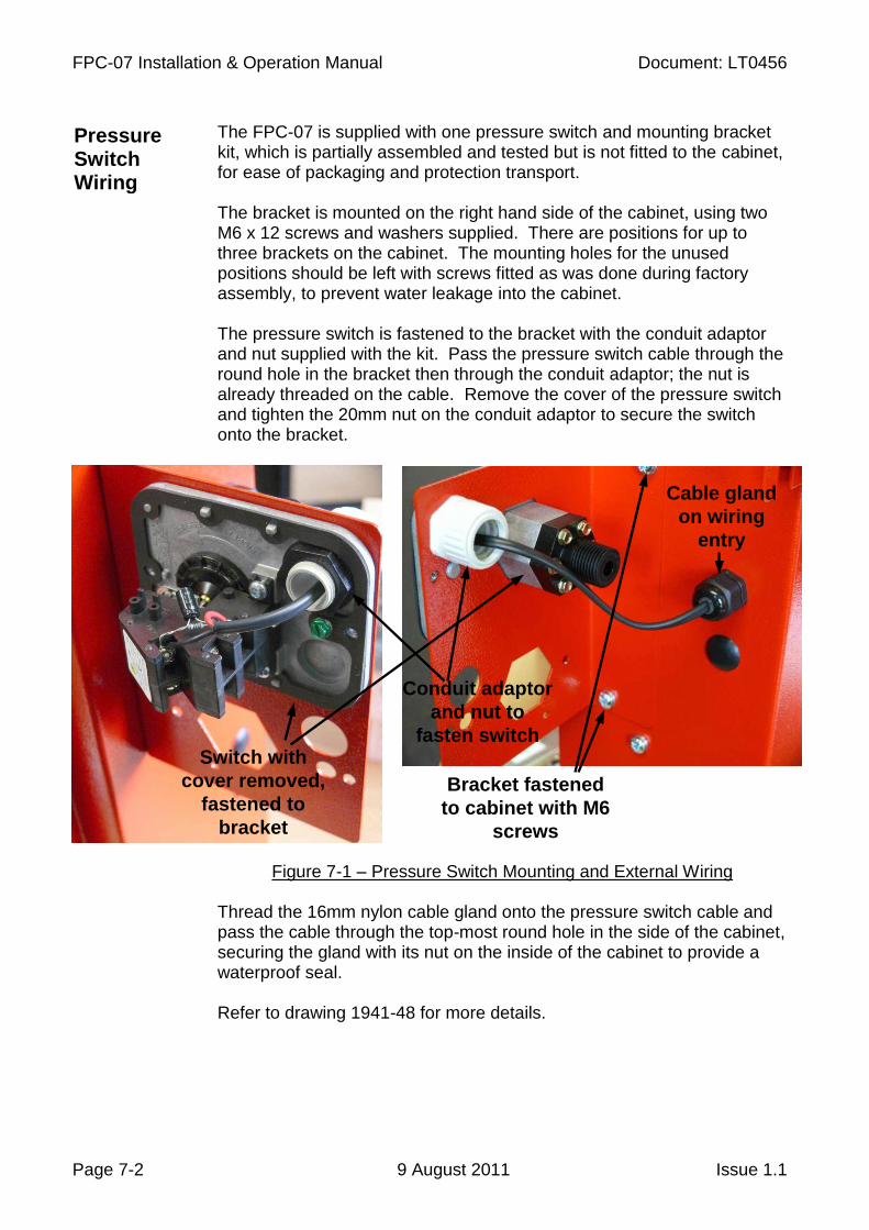
The FPC-07 is supplied with one pressure switch and mounting bracket kit, which is partially assembled and tested but is not fitted to the cabinet, for ease of packaging and protection transport. The bracket is mounted on the right hand side of the cabinet, using two M6 x 12 screws and washers supplied. There are positions for up to three brackets on the cabinet. The mounting holes for the unused positions should be left with screws fitted as was done during factory assembly, to prevent water leakage into the cabinet. The pressure switch is fastened to the bracket with the conduit adaptor and nut supplied with the kit. Pass the pressure switch cable through the round hole in the bracket then through the conduit adaptor; the nut is already threaded on the cable. Remove the cover of the pressure switch and tighten the 20mm nut on the conduit adaptor to secure the switch onto the bracket.
Figure 7-1 – Pressure Switch Mounting and External Wiring Thread the 16mm nylon cable gland onto the pressure switch cable and pass the cable through the top-most round hole in the side of the cabinet, securing the gland with its nut on the inside of the cabinet to provide a waterproof seal. Refer to drawing 1941-48 for more details.
Pressure Switch Wiring
Switch with
cover removed,
fastened to
bracket
Conduit adaptor
and nut to
fasten switch
Bracket fastened
to cabinet with M6
screws
Cable gland
on wiring
entry

Document: LT0456 FPC-07 Installation & Operation Manual
Issue 1.1 9 August 2011 Page 7-3
Inside the cabinet, route the pressure switch cable across the lower edge of the gearplate, below the controller circuit board, to the terminals in the top left corner of this board. Connect the pressure switch to the next free Pressure Switch Input position (1-6). Wiring polarity is not important for the pressure switches. Secure the pressure switch cable with the supplied nylon zip ties.
Figure 7-2 – Internal Pressure Switch Wiring Unused pressure switch inputs should be left unterminated. The controller will be programmed to ignore them. The pressure switch has two sets of contacts, connected in parallel, as required by NZS 4541 and as shown in drawing 1941-48. The screw setting on the switch arm should first be adjusted so that both the contacts operate at about the same pressure (check this by moving the switch arm up carefully by hand and listening for the two clicks at the same position).
Pressure Switch Adjustment

FPC-07 Installation & Operation Manual Document: LT0456
Page 7-4 9 August 2011 Issue 1.1
The actual operating pressure for the contacts can then be set or readjusted using the black adjusting wheel on the pressure switch’s base plate. The FPC-07 is supplied with a pre-assembled and tested umbilical cable, approximately 3 metres long. Drawing 1941-41 shows how this umbilical cable should be wired to the electrical components on the pump set. Note that the wires for different electrical signals are individually coloured as shown on this drawing. Colours are not interchangeable. Damage to the FPC-07 controller may result from incorrect wiring. The following spare parts are available for the FPC-07 controller:
Item Part Number
Additional Pressure Switch Kit FP0946
Charger Module 12V 6A ME0479
Charger Module 24V 6A ME0480
Operator's Manual (supplied with each FPC-07) LT0456
Technical Manual LT0457
Controller circuit board fuses (20x5mm 3A) FU0017
FPC-07 Controller circuit board 1941-38 PA1053
Relay Interface circuit board 1941-40 PA1055
Display circuit board 1941-39 PA1054
Controller Firmware (technician download only) SF0399
Display Panel Keyboard Overlay FA2490
The following drawings relate to the FPC-07 1941-42 Presentation and physical dimensions drawing 1941-51 Alternative mounting arrangements 1941-41 Pump Set wiring details 1941-48 Extra pressure switch installation details
Pump Set Wiring
Spare Parts and Drawings