Embed Size (px)
DESCRIPTION
Manual de Operación de Line Stop Furmanite
Citation preview

CONTENTS
Issue 1 Page 1
General Information 3Specification 4On receipt of equipment 5
Equipment inspection 5
Equipment check list 5
Safety 6Component parts of the Actuator 7Actuator controls 9
Control bar advance/retract 9
Control bar clamp operation 9
Pre-linestopping preparation 11Actuator hydraulic oil filling procedure 11
Plugging head sealing element installation 11
Table 1 - Torque values 12
Line stop housing 13
Plugging head assembly installation 14
Line stop selection 15
Line stop fitting selection 15
Sandwich valve installation 15
Obtaining measurements 15
Plugging head setting distance 16
Installation 17Actuator slinging and lifting 17
Installation of line stop equipment 18
Maintenance 19
Dismantle and re-assembly procedures 19

Page 2 Issue 1
GENERAL INFORMATION
The procedures and instructions contained in this manual should be carefully read and understoodby all personnel concerned with operation and maintenance of this equipment. Using the correctprocedures for operation and maintenance will increase the life of the equipment.
Do not alter the actuator in any way, use only replacement parts manufactured or recommended byIPSCO and, if in doubt, return the machine to the factory for maintenance.
Special attention should be paid to the warnings and cautions in the SAFETY section and elsewherein this manual. They are included to indicate possible dangers to personnel and equipment.
If any part of this manual is not fully understood or questions arise, please contact your nearestInternational Piping Services Company.
The four sizes and part numbers of actuator covered by this manual are as follows:
• 6 in. Thru 12 in. Series 1
• 14 in. Thru 20 in. Series 2
• 22 in. Thru 34 in. Series 3
• 36 in. Thru 48 in. Series 4
Issue 1 Page 3
SPECIFICATION
Maximum actuator hydraulic power requirements: Variable flow at 1000 psi (69 bar)
Maximum pipeline operating pressure: 1800 psi (124 bar)
Maximum end pressure test (Hydrostatic): 2700 psi (186 bar)
Operating temperature: -28.8°C to +83°C(-20°F to +180°F)
Control bar travel: Series 1 - 72 in.Series 2 - 102 in.Series 3 - 140 in.Series 4 - 140 in.
Hydraulic control valve: Mannesman/Rexroth
Cartridge relief valves (see note below): Webtec
Actuator size ranges: 6 in. Thru 12 in.14 in. Thru 20 in.22 in. Thru 34 in.36 in. Thru 48 in.
Note: The control valve manifold is fitted with cartridge relief valves set to 1015 psi ( 70bar) for pressure relief due to thermal expansion. The pressure vents through ahole in the end of the quick release coupling on the return line from the manifold.
Page 4 Issue 1
ON RECEIPT OF EQUIPMENT
EQUIPMENT INSPECTIONThe actuator is thoroughly checked beforeleaving the factory, however, on receipt of deliverythe following checks must be made prior toputting the equipment to use:
• Inspect equipment and report anydamaged or missing equipment to IPSCOimmediately (see equipment check list).
• Inspect the actuator for damage orleakages.
To prevent damage occurringduring transportation andstorage, ensure that theactuator protector/test end isinstalled and the valve guard isin position.
EQUIPMENT CHECK LIST• Line stop Actuator
• Protector/test end c/w 1 inch UNC Studand nut set (8 off)
• Lifting brackets c/w clamping bolts (4 off)
• Head fixing screws c/w Nyloc nuts (2 off)
• Hexagon wrench key.
Issue 1 Page 5
SAFETY
CORRECTLY FITTING PROTECTIVE CLOTHING IS RECOMMENDEDWHENEVER WORKING WITH MACHINERY. LOOSE OR BAGGY CLOTHING CANBE EXTREMELY DANGEROUS WHEN OPERATING OR SERVICING MACHINERY.OTHER ITEMS WHICH SHOULD BE CONSIDERED ARE HARD HAT, GAUNTLETGLOVES, SAFETY SHOES, GARMENTS TO COVER EXPOSED AREAS OF SKINAND BREATHING APPARATUS WHEN A TOXIC ATMOSPHERE EXISTS
DO NOT ATTEMPT AN OPERATION WHICH WOULD DEPART FROM THEPROCEDURES DESCRIBED IN THIS MANUAL. TO DO SO COULD PRESENT AHAZARDOUS SITUATION CAUSING INJURY TO PERSONNEL AND/OR DAMAGETO THE EQUIPMENT.
DO NOT ALTER THIS EQUIPMENT OR ANY OF ITS COMPONENT PARTS. USEONLY REPLACEMENT PARTS MANUFACTURED OR RECOMMENDED BYIPSCO.
Page 6 Issue 1
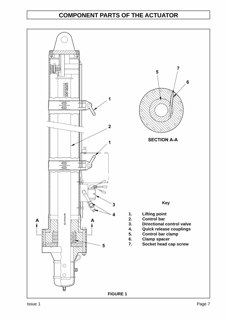
COMPONENT PARTS OF THE ACTUATOR
Issue 1 Page 7
FIGURE 1
Key
1. Lifting point2. Control bar3. Directional control valve4. Quick release couplings5. Control bar clamp6. Clamp spacer7. Socket head cap screw

Page 8 Issue 1
ACTUATOR CONTROLS
Issue 1 Page 9
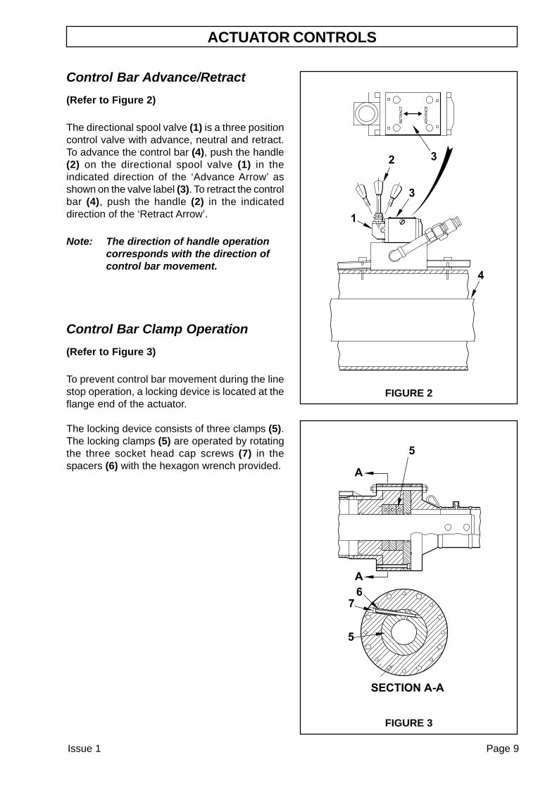
Control Bar Advance/Retract
(Refer to Figure 2)
The directional spool valve (1) is a three positioncontrol valve with advance, neutral and retract.To advance the control bar (4), push the handle(2) on the directional spool valve (1) in theindicated direction of the ‘Advance Arrow’ asshown on the valve label (3). To retract the controlbar (4), push the handle (2) in the indicateddirection of the ‘Retract Arrow’.
Note: The direction of handle operationcorresponds with the direction ofcontrol bar movement.
Control Bar Clamp Operation
(Refer to Figure 3)
To prevent control bar movement during the linestop operation, a locking device is located at theflange end of the actuator.
The locking device consists of three clamps (5).The locking clamps (5) are operated by rotatingthe three socket head cap screws (7) in thespacers (6) with the hexagon wrench provided.
FIGURE 2
FIGURE 3

Page 10 Issue 1
PRE-LINESTOPPING PREPARATION
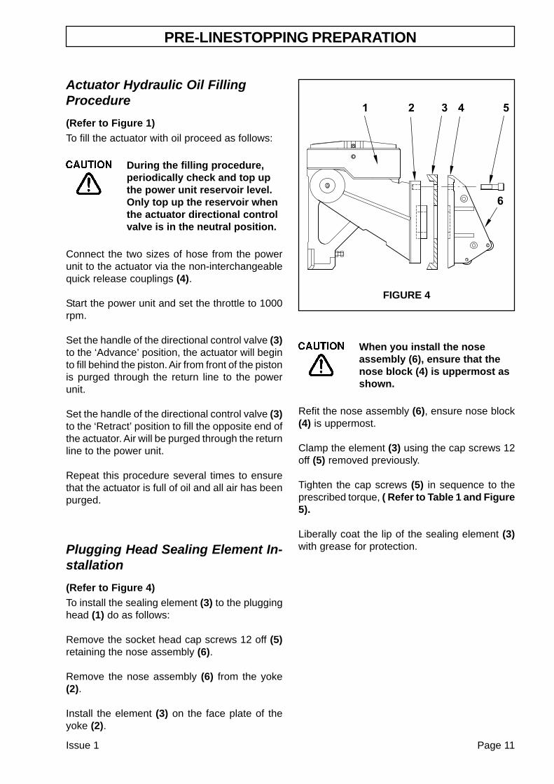
Actuator Hydraulic Oil FillingProcedure
(Refer to Figure 1)To fill the actuator with oil proceed as follows:
During the filling procedure,periodically check and top upthe power unit reservoir level.Only top up the reservoir whenthe actuator directional controlvalve is in the neutral position.
Connect the two sizes of hose from the powerunit to the actuator via the non-interchangeablequick release couplings (4).
Start the power unit and set the throttle to 1000rpm.
Set the handle of the directional control valve (3)to the ‘Advance’ position, the actuator will beginto fill behind the piston. Air from front of the pistonis purged through the return line to the powerunit.
Set the handle of the directional control valve (3)to the ‘Retract’ position to fill the opposite end ofthe actuator. Air will be purged through the returnline to the power unit.
Repeat this procedure several times to ensurethat the actuator is full of oil and all air has beenpurged.
Plugging Head Sealing Element In-stallation
(Refer to Figure 4)To install the sealing element (3) to the plugginghead (1) do as follows:
Remove the socket head cap screws 12 off (5)retaining the nose assembly (6).
Remove the nose assembly (6) from the yoke(2).
Install the element (3) on the face plate of theyoke (2).
FIGURE 4
Issue 1 Page 11
When you install the noseassembly (6), ensure that thenose block (4) is uppermost asshown.
Refit the nose assembly (6), ensure nose block(4) is uppermost.
Clamp the element (3) using the cap screws 12off (5) removed previously.
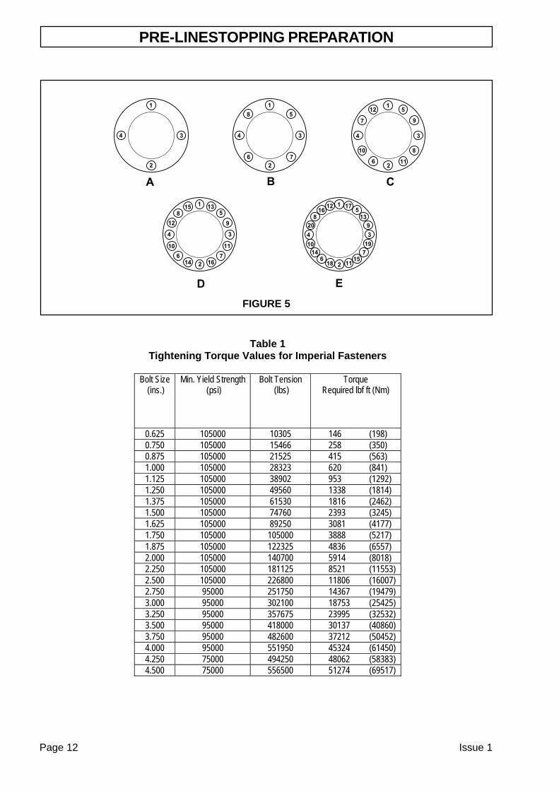
Tighten the cap screws (5) in sequence to theprescribed torque, ( Refer to Table 1 and Figure5).
Liberally coat the lip of the sealing element (3)with grease for protection.
PRE-LINESTOPPING PREPARATION
Page 12 Issue 1
Table 1
Tightening Torque Values for Imperial Fasteners
Bolt Size (ins.)
Min. Yield Strength (psi)
Bolt Tension (lbs)
Torque Required lbf ft (Nm)
0.625 105000 10305 146 (198) 0.750 105000 15466 258 (350) 0.875 105000 21525 415 (563) 1.000 105000 28323 620 (841) 1.125 105000 38902 953 (1292) 1.250 105000 49560 1338 (1814) 1.375 105000 61530 1816 (2462) 1.500 105000 74760 2393 (3245) 1.625 105000 89250 3081 (4177) 1.750 105000 105000 3888 (5217) 1.875 105000 122325 4836 (6557) 2.000 105000 140700 5914 (8018) 2.250 105000 181125 8521 (11553) 2.500 105000 226800 11806 (16007) 2.750 95000 251750 14367 (19479) 3.000 95000 302100 18753 (25425) 3.250 95000 357675 23995 (32532) 3.500 95000 418000 30137 (40860) 3.750 95000 482600 37212 (50452) 4.000 95000 551950 45324 (61450) 4.250 75000 494250 48062 (58383) 4.500 75000 556500 51274 (69517)
FIGURE 5
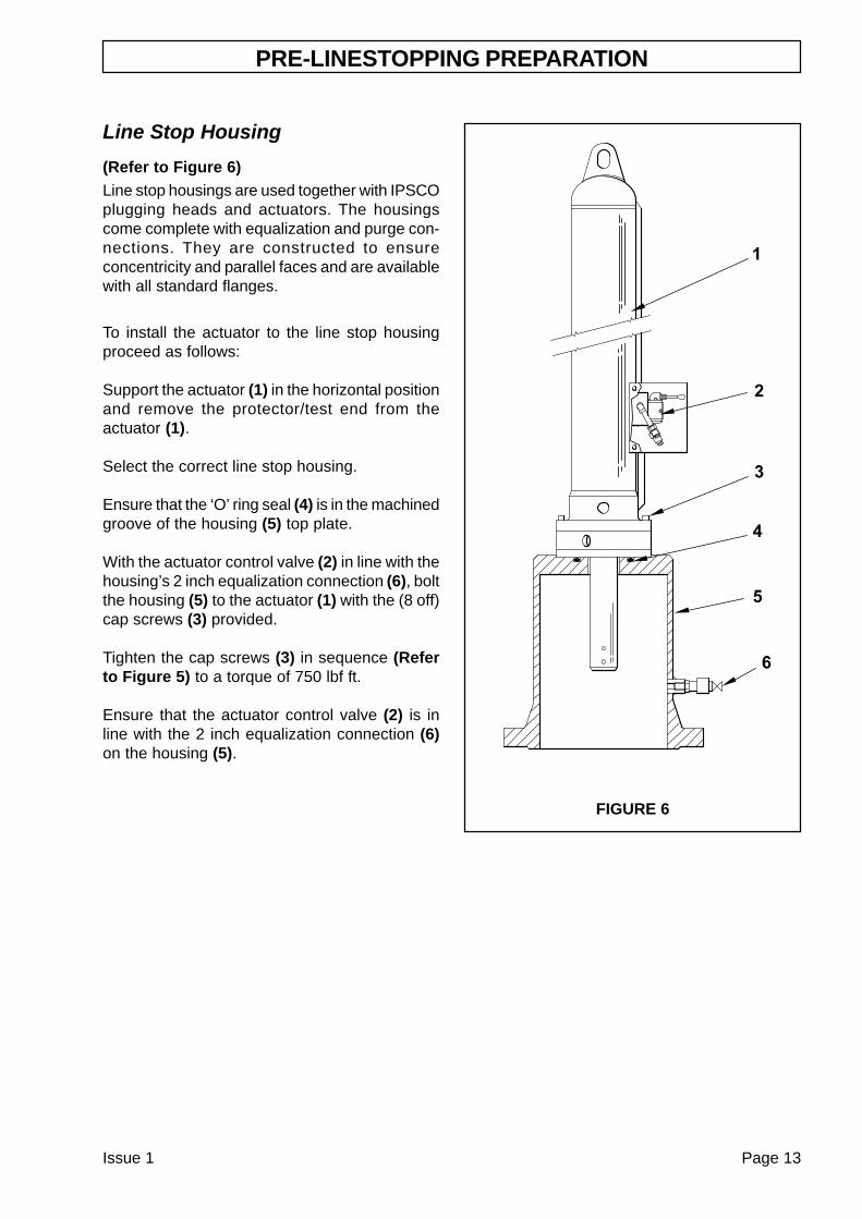
Line Stop Housing
(Refer to Figure 6)Line stop housings are used together with IPSCOplugging heads and actuators. The housingscome complete with equalization and purge con-nections. They are constructed to ensureconcentricity and parallel faces and are availablewith all standard flanges.
To install the actuator to the line stop housingproceed as follows:
Support the actuator (1) in the horizontal positionand remove the protector/test end from theactuator (1).
Select the correct line stop housing.
Ensure that the ‘O’ ring seal (4) is in the machinedgroove of the housing (5) top plate.
With the actuator control valve (2) in line with thehousing’s 2 inch equalization connection (6), boltthe housing (5) to the actuator (1) with the (8 off)cap screws (3) provided.
Tighten the cap screws (3) in sequence (Referto Figure 5) to a torque of 750 lbf ft.
Ensure that the actuator control valve (2) is inline with the 2 inch equalization connection (6)on the housing (5).
PRE-LINESTOPPING PREPARATION
FIGURE 6
Issue 1 Page 13
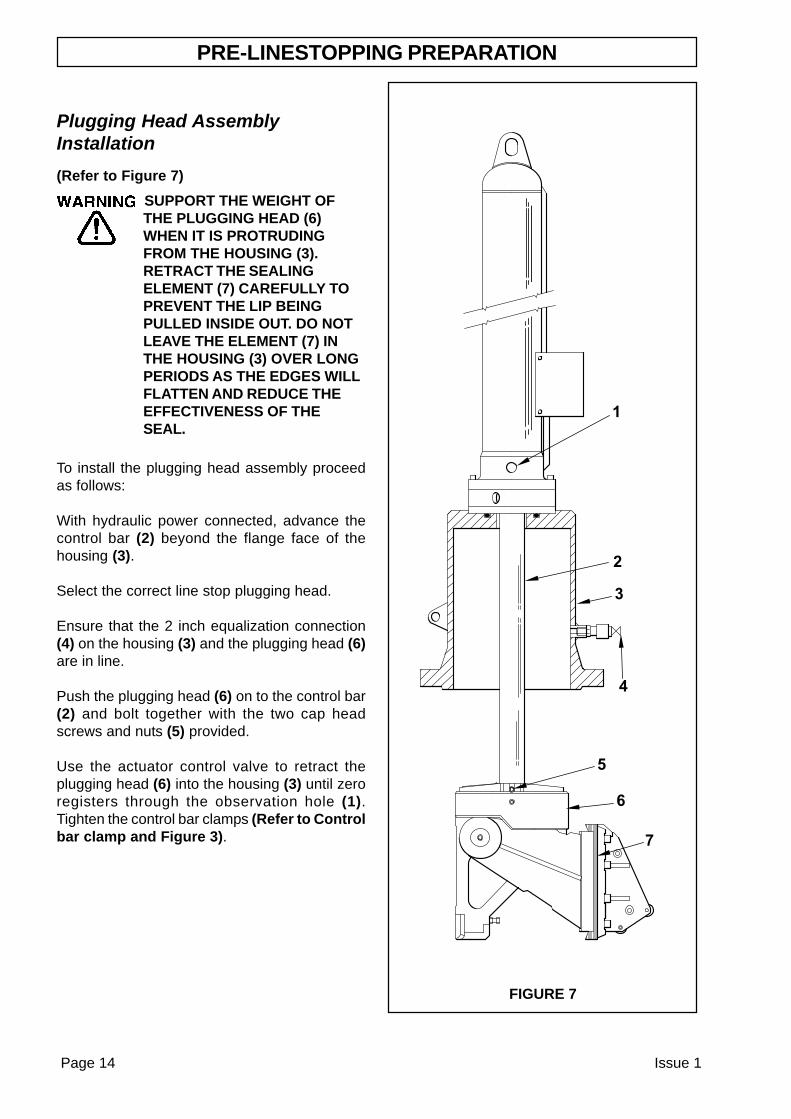
FIGURE 7
Page 14 Issue 1
PRE-LINESTOPPING PREPARATION
Plugging Head AssemblyInstallation
(Refer to Figure 7)
SUPPORT THE WEIGHT OFTHE PLUGGING HEAD (6)WHEN IT IS PROTRUDINGFROM THE HOUSING (3).RETRACT THE SEALINGELEMENT (7) CAREFULLY TOPREVENT THE LIP BEINGPULLED INSIDE OUT. DO NOTLEAVE THE ELEMENT (7) INTHE HOUSING (3) OVER LONGPERIODS AS THE EDGES WILLFLATTEN AND REDUCE THEEFFECTIVENESS OF THESEAL.
To install the plugging head assembly proceedas follows:
With hydraulic power connected, advance thecontrol bar (2) beyond the flange face of thehousing (3).
Select the correct line stop plugging head.
Ensure that the 2 inch equalization connection(4) on the housing (3) and the plugging head (6)are in line.
Push the plugging head (6) on to the control bar(2) and bolt together with the two cap headscrews and nuts (5) provided.
Use the actuator control valve to retract theplugging head (6) into the housing (3) until zeroregisters through the observation hole (1).Tighten the control bar clamps (Refer to Controlbar clamp and Figure 3).
Issue 1 Page 15
PRE-LINESTOPPING PREPARATION
Line stop Valve SelectionOnly IPSCO sandwich valves should be usedduring line stopping operations. For moreinformation on sandwich valves refer to thesandwich valve manual.
Line stop Fitting SelectionOnly IPSCO full encirclement type fittings arerecommended for line stop operations..
It is imperative that all fittings are manufacturedand attached to the pipeline accurately.
Alignment of the fitting to the pipeline is crucialto the success of the line stop operation.
Sandwich Valve InstallationRefer to your sandwich valve manual and tappingmachine operation and maintenance manual forinstallation of the sandwich valve.
On completion of the hot tapping procedure andthe onset of the line stop equipment installation,the sandwich valve will already be in place andin the closed position.
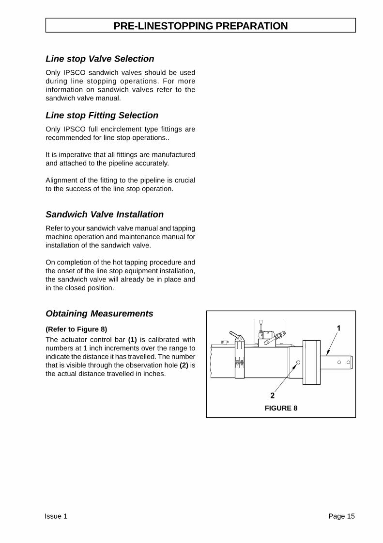
Obtaining Measurements
(Refer to Figure 8)The actuator control bar (1) is calibrated withnumbers at 1 inch increments over the range toindicate the distance it has travelled. The numberthat is visible through the observation hole (2) isthe actual distance travelled in inches.
FIGURE 8
Page 16 Issue 1
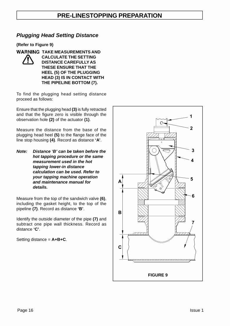
Plugging Head Setting Distance
(Refer to Figure 9)
TAKE MEASUREMENTS ANDCALCULATE THE SETTINGDISTANCE CAREFULLY ASTHESE ENSURE THAT THEHEEL (5) OF THE PLUGGINGHEAD (3) IS IN CONTACT WITHTHE PIPELINE BOTTOM (7).
To find the plugging head setting distanceproceed as follows:
Ensure that the plugging head (3) is fully retractedand that the figure zero is visible through theobservation hole (2) of the actuator (1).
Measure the distance from the base of theplugging head heel (5) to the flange face of theline stop housing (4). Record as distance ‘A’.
Note: Distance ‘B’ can be taken before thehot tapping procedure or the samemeasurement used in the hottapping lower-in distancecalculation can be used. Refer toyour tapping machine operationand maintenance manual fordetails.
Measure from the top of the sandwich valve (6),including the gasket height, to the top of thepipeline (7). Record as distance ‘B’.
Identify the outside diameter of the pipe (7) andsubtract one pipe wall thickness. Record asdistance ‘C’.
Setting distance = A+B+C.
PRE-LINESTOPPING PREPARATION
FIGURE 9
Issue 1 Page 17
INSTALLATION
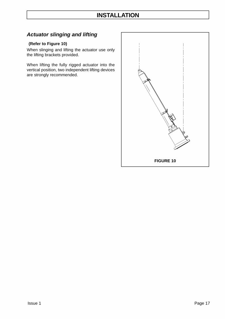
Actuator slinging and lifting
(Refer to Figure 10)When slinging and lifting the actuator use onlythe lifting brackets provided.
When lifting the fully rigged actuator into thevertical position, two independent lifting devicesare strongly recommended.
FIGURE 10
Installation of Line stop Equipment
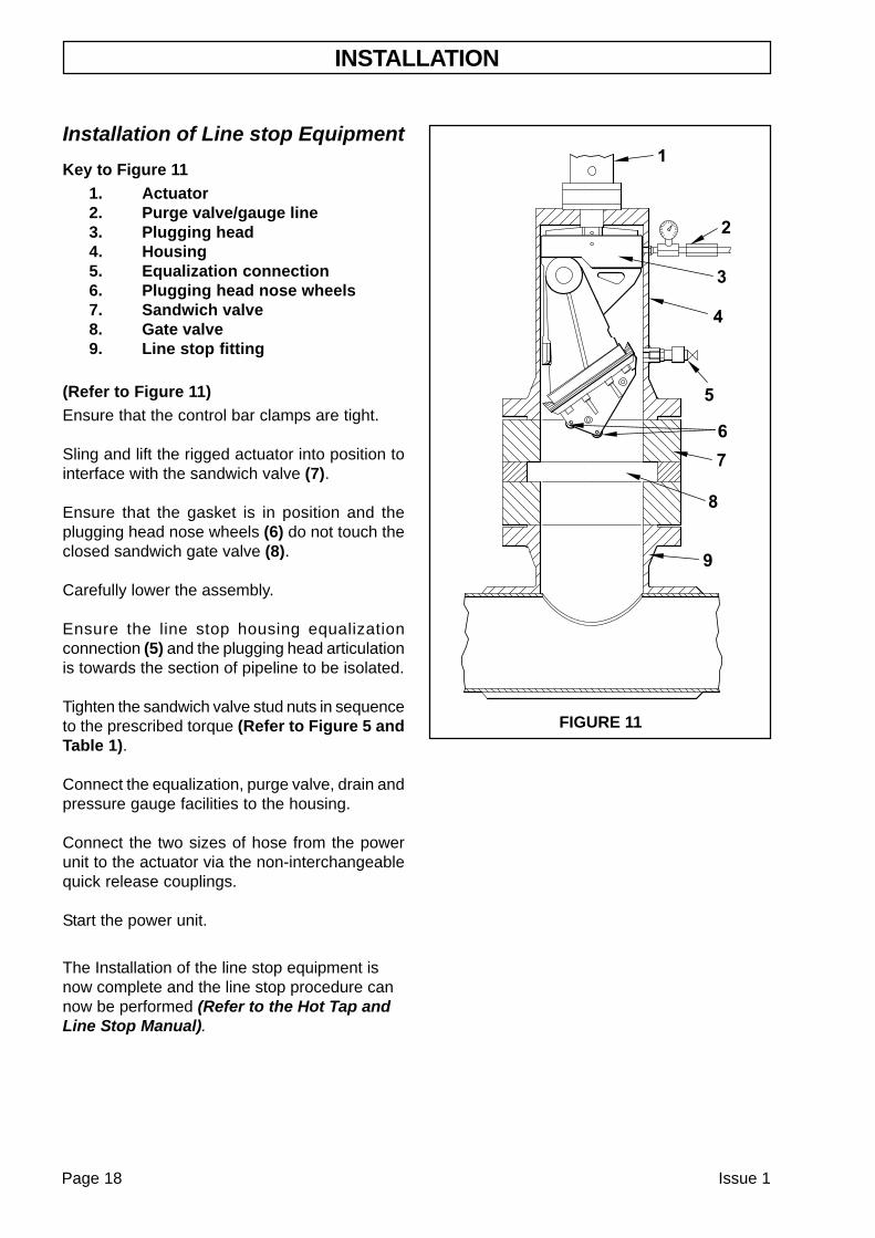
Key to Figure 111. Actuator2. Purge valve/gauge line3. Plugging head4. Housing5. Equalization connection6. Plugging head nose wheels7. Sandwich valve8. Gate valve9. Line stop fitting
(Refer to Figure 11)Ensure that the control bar clamps are tight.
Sling and lift the rigged actuator into position tointerface with the sandwich valve (7).
Ensure that the gasket is in position and theplugging head nose wheels (6) do not touch theclosed sandwich gate valve (8).
Carefully lower the assembly.
Ensure the line stop housing equalizationconnection (5) and the plugging head articulationis towards the section of pipeline to be isolated.
Tighten the sandwich valve stud nuts in sequenceto the prescribed torque (Refer to Figure 5 andTable 1).
Connect the equalization, purge valve, drain andpressure gauge facilities to the housing.
Connect the two sizes of hose from the powerunit to the actuator via the non-interchangeablequick release couplings.
Start the power unit.
The Installation of the line stop equipment isnow complete and the line stop procedure cannow be performed (Refer to the Hot Tap andLine Stop Manual).
FIGURE 11
INSTALLATION
Page 18 Issue 1
MAINTENANCE
Issue 1 Page 19
The actuator ‘O’ ring seals should be replacedduring any dismantling and the annual overhaulof the actuator.
The scraper seal, pressure seals and piston sealsshould be replaced when signs of any wear ordamage are found.
The maintenance and regular replacement of thepressure seals is very important. They provide abarrier between cylinder pressure and thepressurized pipeline environment.
Before leaving the factory, the front pressure sealis tested to 2700 psi using the protector/test end.
Before each line stop operation, the actuatorshould be pressure tested to 2700 psi for 30minutes. If a pressure drop is detected, the frontpressure seal should be replaced.
The control bar end should be coated with lightoil before long periods of storage.
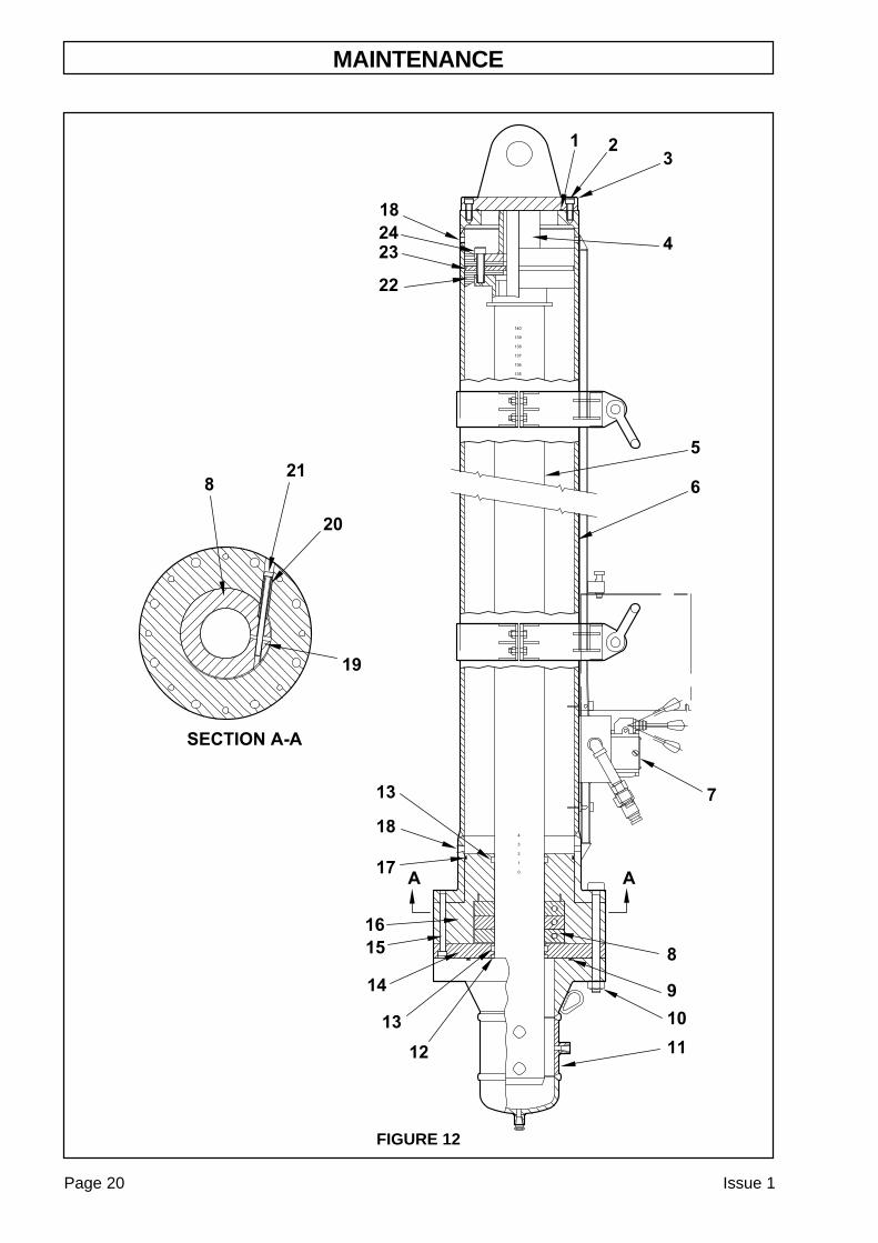
Dismantle and Re-AssemblyProcedures
(Refer to Figure 12)
Note: Before the installation of a seal youmust ensure the seal seating area isclean.
Dismantle Procedure
To dismantle the actuator, proceed as follows:
Position the actuator in the horizontal positionwith the two pressure plugs (18) face down.
Remove the eight stud and nut sets (10) andremove the protector/test end (11).
Remove the two pressure plugs (18) and drainthe fluid from the cylinder body (6) into a suitablecontainer.
Remove the twelve cap screws (2) and the endflange assembly complete with anti-rotation bar(3).
Remove and discard the O-ring seal (1).
Remove the eight cap screws (15) from the sealhousing (14).
Slide the seal housing (14) and clamp housing(16) complete with control bar clamps (8) fromthe control bar (5).
Remove and discard the O-ring seal (17) onclamp housing (16).
Remove the three cap screws (21) and threeclamp spacers (20) from the clamp housing (16).
Remove the three control bar clamps (8) and pin(19) from the clamp housing (16).
Support the control bar when itis removed from the cylinder.
Use the two holes in the end of control bar (5) topull the control bar piston free from the cylinderbody (6).
Re-Assembly Procedure
To re-assemble the actuator proceed as follows:
Examine the two piston seals (22) for wear ordamage. To replace worn or damaged pistonseals (22), do as follows:
Remove the six cap screws (24), bar stop (4)and the anti-rotation plate (23). Replace the twopiston seals (22) and refit the anti-rotation plate(23) and bar stop (4) to the control bar (5). Clampthe assembly with the six cap screws (24) insequence to the prescribed torque (Refer toTable 1 and Figure 5).
Support the control bar (5) and guide the leadingpiston seal into the cylinder (6) to preventdamage. Refit the control bar (5) to the cylinder(6).
Refit the pin (19) and three bar clamps (8) toclamp housing (16).
Refit the three clamp spacers (20) and three capscrews (21) to clamp housing (16).
MAINTENANCE
Page 20 Issue 1
FIGURE 12
Note: If the pressure seal (13) is to bereplaced in the clamp housing (16),you must ensure the pressure sideof the seal (13) is assembledagainst the cylinder internalpressure.
Examine the pressure seal (13) in clamp housing(16) for wear or damage. If wear or damage isfound, replace the pressure seal (13). Ensure thepressure side of the seal (13) is against thecylinder internal pressure.
Install new O-ring (17) to the clamp housing (16).
Slide the clamp housing (16) onto the control bar(5) and into the main cylinder body (6). Align theobservation hole in main cylinder body (6) withthe hole in the clamp housing (16).
Note: If the pressure seal (13) is to bereplaced in the seal housing (14),you must ensure the pressure sideof the seal (13) is assembled facingthe external product pressure.
Examine the scraper seal (12) and pressure seal(13) in the seal housing (14) for wear or damage.If wear or damage is found, replace the scraperseal (12) and pressure seal (13). Ensure thepressure side of the seal (13) is facing theexternal product pressure.
Slide the seal housing (14) onto the control bar(5). Clamp the seal housing (14) with the eightcap screws (15) in sequence (Refer to Figure5) and torque tighten to 120 lbf ft.
Install new O-ring (1) to the end flange (3).
Slide the anti-rotation bar through the centre ofthe control bar (5) and align end flange (3) to themain cylinder body (6). Ensure the lifting eye isin line with the directional control valve (7).
Refit the twelve cap screws (2) in sequence(Refer to Figure 5) and torque tighten to 80 lbfft.
Refit the two pressure plugs (18) to the cylindermain body (6).
Replenish the actuator with hydraulic oil andcheck operation as detailed previously (Refer toActuator hydraulic oil filling procedure).
Fully retract the control bar (5).
Refit the protector/test end (11) complete withO-ring (9) and clamp with the eight stud and nutsets (10).
MAINTENANCE
Issue 1 Page 21

Page 22 Issue 1


IPSCO (UK) Ltd.Sunningdale HouseSunningdale RoadSouth Park Industrial EstateScunthorpeUnited KingdomDN17 2TYTel. 00 44 1724 849904Fax. 00 44 1724 861033EMAIL: [email protected] PAGE: www.ipscouk.com
Issue 114 February 2003