Embed Size (px)
Citation preview

we IN THIS ISSUE:
Field Findings
Checking Vide ynch Waveform
Feedback & Phase Inversion
Tuned Filters
A New Phono Pickup
Inco W :, .It's Easy!
High Temperature is Tough on LONG LIFE ...
Long life in a capacitor is one thing-long life in high temperature is quite another matter. That's why the record of Mallory Capacitors is
so impressive. Tests prove that the characteris- tics of Mallory Capacitors are practically un- changed after 2000 hours at a temperature of 185° F.
It takes materials of the highest purity to withstand heat like that. But purity control is
one of the big points in the manufacture of Mallory Capacitors. They are untouched by
human hands; production workers wear rubber gloves. Specifications on the chloride content of the gauze are even more rigid than on hospital gauze. This gauze is the base on which aluminum is sprayed to create the anode plate.
Mallory Capacitors Can Take It !
That's not all! Mallory Capacitors have longer shelf life-longer life in an inactive set- lower RF impedance-ability to withstand higher ripple current.
Mallory Capacitors cost no more than ordinary capacitors-they're easy to install, and when they're installed they're dependable . . . and that means the kind of service that satisfies customers. Order from your Mallory distributor.
New Improvements in Mallory FP Capacitors
Feature stronger anode tabs - withstand higher discharge currents-improved high surge separators-still greater heat resistance-extra heavy rubber seal-heavier cathode tab-special etched cathode.
Buy Mallory Assured Quality At Regular Price Levels
P. R. MALLGr<v d CO..Inc.
MALLO R CORS ... CONTROLSBRATORS .. .
SWITCHES . . . RESISTORS . . . RECTIFIERS . . .
VIBRAPACK* POWER SUPPLIES ... FILTERS *Reg. U. S. Pat. Off.
APPROVED PRECISION PRODUCTS P. R. MALLORY & CO., Inc., INDIANAPOLIS 6, INDIANA
SYLVANIA ADVERTISING HELPS SERVICE DEALERS
INCREASE THEIR SERVICE BUSINESS!
Read what
these 3
say about aign dealers Camp
. , Dealer Ivana
s
Summer
and 1all
yfo r s u rvlce Gunwale
Se e.rnd'^
1°°+"' o N,F M R^
VI -11C ..º
v.R d^" cet, ulsa.
October 2.6,
1948
varteE°t 1
D0MD14 ]006 ED
PpOlo N £i`NDI10 S r
,SCn Rad i
"September business increased 30°0" oducts lno
Y Ys tlon tO he.,
?m2°ri'
vou]d ]Lkà a° vee oent nad ofeel
SY] tr, [ evbe¡
our e s
, ;: ç° P 1gn n]npe we
hevy ueed
t thus thts trod,o sP°epo teT sd1n our
LL heºe shthe ¿th. PeP°r
ead Che radrelylcethenks
to
peper]t L 6. e pro sd o Ln°zp
ycu ct SY]veti ,c +lr/Y
tr,ilY Y°ur.
Ve/rvpO^.'r P td
eneer
SYLVANIA'S FEBRUARY, MARCH AND APRIL CAMPAIGN IS NOW READY. Here's what it contains:
3 Postal Card Mailings-one for each month.
3 Window Displays-one for each month.
3 Window Streamers-one for each month.
6 Newspaper Ad Mats-two sizes for each month.
Radio Spot Announcements-several for each month.
SEND FOR FULL INFORMATION NOW! Remember, this campaign designed for your use ties tip directly with Sylvania's ad campaigns on a national scale. You pay only the postage on the government postal cards you mail. Sylvania supplies everything else free! Mail coupon today!
SYLVAN I.1 ELECTRIC
RADIO TUBES; CATHODE RAY TUBES; ELECTRONIC DEVICES; FLUORESCENT
LAMPS, FIXTURES, WIRING DEVICES; LIGHT BULBS; PHOTOLAMPS
r
L
ce
h aj53
ChuP.
"Newspaper ads brought in over 100
radio sets for repair during July!" ha
<n jO Ae.t p{oErv'
wad F°<
7 h,,
tti" pr w ie' , 1' errl°. l.
r
°] t <Fr! pGAY
Fts. t' sUY t T.bl u9< wr try(iDdse erYr. ß'tY<r °<<r .FlOF e, e' F1 :dr°(<le fael¡° ot Your dtuAO
tyy
el;e,n to`;a ofY<y °Y eo dr{°1º
AoN Go,ed ,nY d nY °oPl P'r. tF thN touóh<, ó
11 tll
dY
ltE{e t o1 P P°' {<1'lóó )u1Y
By L¡ey eº°]:¡'uó<F, t ShoPFID óS d( <F
t 00 F'' t 1t,pdt <YP <M
atov °p°
d C FlaFr!Mpÿo y
1 arY é°'r etot f t < thle oaH1Y
our.
oAe1r°up0 ó¡ 11 a11 Ai
o' n t buelt' 6 Y V: &dl .(N ehop Q,aon + l,<h ,1t
5 i,etd{o.
L6 FOURTNMYAVF_, WERS[Si
RADIO SERVICE CO.
Advertising Departee
Sylvania Electric nt Emporium, Pa,
Dear Sir;
PHONG 1564 ASHLAND,
WISC.
"Gross business increased from $90.00 to $135.00 per week"
writi.g tell you
advertising has helped my business,
how much your co- ord ineted
I have used the postal carda,
end the radio spot announcements
to promote Y
spot announcements the window dleple s radio station. are used seven times
a week The taced a large range ofrpeople at various hours ao
over
have local
cale I make my entirely
through buse of used records,
bus very valuable ta ming which help, eto
beenrvice
and the
my per weekto m business,
he, increeeed e.
Sfrom ce
e have
increase
n average of
$135.00 per week hae in
ex-
pense nhevecoat
me b ut $f .00. Before gross.
I used lithe ocampaign
wee s ut
e certainly
received per week. fair returnr
the extra ax - booklet
I
am very rush please
d with the radio spot in your
yyere rvice
o.
Sylvania Electric Products Inc.
Advertising Department Room R-1801 Emporium, Pa.
Gentlemen: Please send me full details on your February, March and
April Service Dealer Campaigns.
Name
Company
Address
City
State
Zone
RADIO SERVICE DEALER JANUARY, 1949
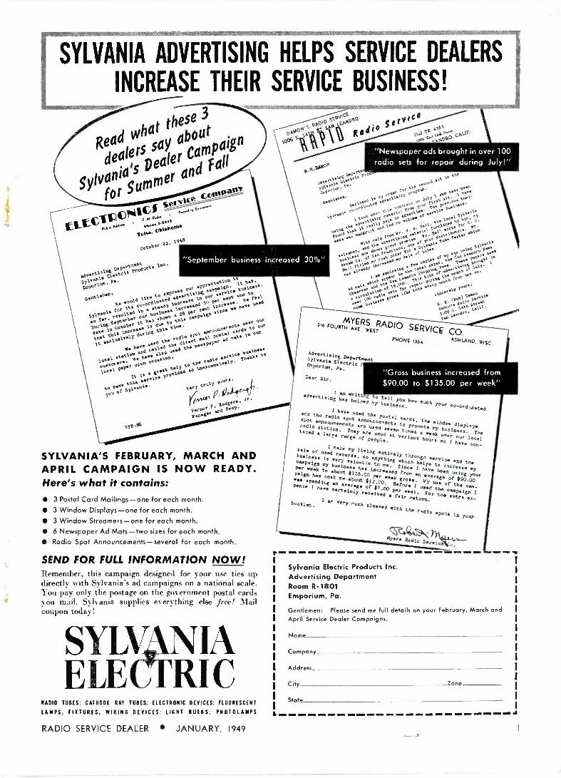
EDITORIAL Dual Speed Player Standards
The advent of dual speed reco d players, combination 78-33 1 /3 rpm jobs, gave the industry a big, well needed boost. The original method of launch- ing the new player units and records left much to be desired, but witth passing time has been getting straight- ened out.
Dual speed players afford owners with many advantages such as im- proved quality and economy. Likewise, the units afford Service Dealers with an opportunity to make sales and re- placements, otherwise not obtainable.
However, now there's a "fly in the ointment". It seems that one or two very big manufacturers did not jump on the 33 1 '3 rpm slow -speed band- wagon, preferring to establish a slight- ly different standard, either 45 rpm or 59 rpm for the combination with 78 rpm. If their plans to bring out dual speed players with 78-50 rpm ranges, and if their plans to bring out new phonograph records that will play only at 59 rpm are carried through to a conclusion, obviously, a great deal of confusion will result. We believe that if the record and record-player buy- ing public gets tangled in a maze of different speed ratings, the whole busi- ness may be jeopardized. Thus, as we see it, RMA should get all the factors together immediately and establish once and finally what are to be stand- ards for dual speed players and slow - playing records.
Test Equipment Issue
A radical departure from our regu- lar publishing practice takes place next month. For the first time since "RSD's" inception almost 10 years ago we will have a special issue in Feb- ruary. We will call it our Test Equip- ment Number.
Its purpose is to acquaint radio tech- nicians, dealers and students with the fundamental characteristics, limitations and applications of the 11 basic types of test equipments required in present- day AM -FM and TV servicing. Thous- ands of radiomen are using obsolete test equipment and have been reluct- ant to make new purchases until they could learn from an authoritative source just what the score is. Our February issue will be outstanding be- cause it will dispel all confusion in this regard.
"LIFE" Reviews TV Progress
The December 6th issue of "LIFE" reviews the progress of radio and video quite comprehensively. One must respect some of "LIFE's" observations, to wit: it calls television, "America's newest big industry". Continuing, there were such remarks as . . . "Television no longer threatened to bring theatre
[Continued on page 481
Sanford R. Cowan EDITOR PI BLUSHER
Samuel L. Marshall MANAGING EDITOR
COWAN P 1' R I.I ti Il IN 1: Corp.
Vol. 10-\o. I
.1c" 1 :`ln. 19.19
Editorial
Field Findings, by S. R. Cowan Industry happenings here and there
Trade Flashes
Checking Video & Synch Waveforms Using a C.R.O., Part 2 by Samuel L. Marshall Second and concluding installment on this subject
Feedback & Phase Inversion, Part I, by C. A. Tuthill Principles and applications of feedback and phase inversion systems
Tuned Filters, by Rufus P. Turner 22 Applications of tuned filters in transformerless power supplies
A New Phono Pickup, by Ralph M. Baruch 24 Characteristics and applications of the ' Tifone" pickup
TV Picture Tube Characteristic Chart 26 Detailing the essential characteristics of all TV picture tubes
Circuit Court 28 Garod I 1 FMP, Westinghouse H-186, H-187, Philco Model 49-1613, Crosley 65 ST series, Motorola 107F series
Service -Dealer Associations Y9 Complete listing of Service -Dealer associations, their addresses, and their presidents or secretaries
Income Tax-It's Easy! by Betty Lee Gough 30 Income Tax returns simplified for the Radio Service Dealer
New Products 31
SANFORD L. CAHN National Advertising Sales Manager
JEAN M. WHEELER, Circulation Manager BRANCH: J. C. GALLOWAY 816 W. 5th St.,
2
4
12
15
20
HARRY N. REIZES Advertising Manager
DAVID SALTMAN, Production Manager Los Angeles 13, Calif., Mutual 8335
Entered as second class matter at the Post Office at New York, N.Y., under the Act of March 3, 1879. Subscription price: $2.00 per year in United States, U.S. Possessions & Canada;
elsewhere $3.00. Single copies: 25e. Entire contents Copyright 1949, Cowan Publishing Corp.
2 RADIO SERVICE DEALER JANUARY, 1949
G EN ER E LE CTRIC FIRST AND SREAT ME IN ELECTRONICS
RADIO SERVICE DEALER JANUARY, 1949 3

JIEJI iJlrJinqA A resume of Industry happenings here, there and everywhere
Unusual TV Installation Harry Ward, E. Anaheim St.,
Long Beach, Cal., Service Dealer and active member of the Long Beach Radio Technician's Ass'n., found a unique way to make a satisfactory TV set installation in a Barber shop located across the street from his store.
Conventional TV arrays failed to give satisfactory reception, as in ev- ery case there was excessive interfer- ence due to auto ignition. Finally, Mr. Ward rigged up a window screen, as shown in the illustration, position- ing it below the dipole. This trick solved the problem-and now, through- out Long Beach, one can see many TV antennas with various types of chicken wire or screen vertical -wave - absorption devices attached.
Another TV Antenna Ban An Elizabeth, N.J. housing project.
prohibits tenants from erecting roof TV antennas. To get around this ban some tenants installed aerials on arms extending out of their windows. This infuriated the Chairman of the housing project. He not only claimed that such out -the -window installa- tions were a violation of the local law, (which we do not believe is true), he also claimed such window installations are fire hazards, (which we are inclined to scoff at because of the ridiculousness of the claim). To top it off, The Chairman really let the cat out of the bag when he stated that if people are rich enough to own a television set they are rich enough to live in a higher rent type of building project. That is sheer nonsense, for if politicians don't realize that even poor people can af- ford to buy TV sets for as little as $3.50 a week, they should learn more about the facts of life.
In a nutshell, renters hate TV un- less they can use it to squeeze a few extra bucks out of the tenants. The situation is one that R.M.A. and N.A.B. should do something about ... and they should do it now!
by S. R. COWAN
California's contribution to the problem of licking vertical pickup.
The New Video Wire Link Effective January 12th the new
telephone company link that ties the Eastern and Midwestern video net- works into an integral unit brought acclaim and huzzahs from al] branches of the video industry. In time, and that timo should not be too far off, this country will have video links from Coast -to -Coast, so that live -talent shows or sporting ievents originating at Hollywood, Chicago or New York can be tele- cast in all cities having TV outlets simultaneously.
Television's biggest weekness, sine's its inception, has been the inferior quality of the programs. Networks are the first and most important step in eliminating that shortcoming. For example, the 1948 Baseb9ll World Series games were split into two parts, from a video point of view, as the games played in Boston could only be seen on TV in the East, in cities on the Eastern network, and the Detroit games could only be tele- cast to the Midwest cities situated on the Midwestern net. Had the new telephone company link been in oper-
ation at World Series time both networks culd have carried all the games.
The time zone difference between East and West is going to be af- fected by TV and it will not be as simple a problem to lick on video as it was on conventional AM. It's much too expensive to rebroadcast a live talent video show to take advantage of the time difference, as is now done on AM programs. From where we sit, it would seem as though the West Coast is the one that is going to have to "push its viewing hours ahead". There is now a two hour time difference between Hollywood and New York. (Normally there would be a three hour difference but the West Coast is still operating on Daylight Saving Time due to the drought). Thus, if zone times were normal, a big show put on at New York at 8 p.m. New York time, were there a Coast -to -Coast link, would be on the air in California at 5 p.m., and that's a little too early. Full advantages of national commercial sponsorship would not be obtained.
Incidently, it is time that one ap- preciated the new, true status of the Wes Coast, in -so -far as population is concerned. The next national census may show that California has a popu- lation almost as big as New York's. There has been, and there continu- ally is an ever-increasing migration towards the West Coast. There is a greater shortage of radio technicians out West than in the East or Mid- west. So, if any readers have been pondering about a trek to the West in line with Greeley's sage advice, you now have the facts. (It cannot be denied, even by a staid Connecti- cut Yankee like me, that the climate and hospitality of the West are factors quite definitely in its favor).
Business Conditions We have entered a New Year and
what the future will bring only time itself can tell. My prognostications may or may not he borne out.
4 RADIO SERVICE DEALER JANUARY, 1949

RE HOU
OF
SERVICE MICROPHONE
CABLES
RADIO SERVICE DEALER JANUARY, 1949
8412
8423
5

PRESENTS
THE NEW
MODEL 12CL TV KIT Brings the biggest and hest in tele- vision within the reach of everyone.
MODEL 12CL TV KIT Features 121/4" tube with fitted All -Angle Lens, giving over 200 sq. inch picture which is visible from anyplace in a room. Gives ideal long-range reception with CONTINUOUS TUNING on ALL CHAN- NELS. COMPLETE with Cabinet. Lens, Roto - Table, Antenna, Lead-in Wire. A BIG PROFIT -MAKER for service deal- ers. This kit is TOPS-ideal for homes, clubs, taverns, and other commercial in- stallations.
EASY TO ASSEMBLE . NO TECHNICAL KNOWLEDGE REQUIRED Transvision's simple step-by-step Instruction Sheet makes assembling a TV Kit a pleasure. Each kit comes complete with all -channel double -folded dipole antenna and 60 ft. of lead-in wire. Nothing else to buy!
TRANSVISION ALL -CHANNEL TELEVISION BOOSTER
To assure television reception in weak signal areas, or areas which are out of range of certain broadcast stations, Transvision engi- neers have designed this new booster. It in- creases signal strength on all television chan- nels. Tunes all television channels continuous- ly. Can be used with any type of television receiver. Unusually high gain in upper tele- vision channels. Model B-1 LIST $44.95
TRANSVISION COMPLETE LINE OF TELEVISION COMPONENTS
Essential units for building a quality tele- vision set . . Transvision makes available a complete line of high quality parts com- petitively priced. Included in this line are Filter Chokes, all types of Transformers, Focus Coils, Deflection Yokes, Coils-and of course major units such as Picture Tubes, Antennas, Lenses, etc., etc. WRITE FOR COMPONENTS FOLDER P-1
RADIOMEN..You Can GET INTO The
TELEVISION BUSINESS IN A BIG WAY WITH THE
TRANSVISION DEALER PLAN
Write for Dealer Folder D-1
GIGANTIC VALUE! OVER
2 0 0 SQ. IN. PICTURE
VISIBLE from ALL ANGLES ( Picture much bigger than a tabloid news-
paper page) IMAGE IS EQUAL to that of a 20" tube- even sharper and clearer-and it is visible
from all angles.
$39 00 9 NET
Includes Kit, Cabinet, Lens. Table, Antenna, 3: 60 ft. of Lead-in Wire
EQUIVALENT OF $1000.00 SETS! Price of the new 12CL elect ,°magnetic kit includes these outstanding features: - 01 12r/" picture tube with special fitted All -
Angle Lens and color kit. Beautiful select -grain cabinet and roto -table. New all -channel continuous tuner Model CT -1. New all -channel hi -gain antenna ;Ind 60 feet of lead-in wire. Nothing else to buy.
Transvision Remote Control Unit Kit \\'ill operate any TV receiver from a distance. Turns set on, tunes in stations, controls contrast and brightness, turns set off. Ideal for installations where the television receiver is inaccessible. Tuner unit is a high gain. all -channel unit with about 50 micro -volt sensitivity. Easy to assemble in about an hour. Model TRCU, with 25 feet of cable
Net $69.00 Without cabinet Net $65.00
ASSEMBLE Your Own CABINETS Transvision's "MODULAR" Cabinets come in knock-down, unpainted units, offering an un- limited range of combinat ons, including even a bar. Finish them off to suit your taste.
Corner piece, shown above, has room for TV, Phono, Record Storage, and open Book Case. COMPLETE Net $84.00
For other units and prices, writ, for "Modular" Catalog.
TRANSVISION, Inc. Dept. RSD New Rochelle, N. Y. In Calif.: Transvision of California, 8572 Santa Monies Blvd., Hull wood 46.
All prices 5`c higher west of Mississippi: all prices fair traded. All Prices Subject to Change.
6
1. call not see a AVttr in the im- mediate offing. To begin with, Com- rade Stalin has purged his top army brass again. I don't believe he would take such steps if he believed that war was imminent. It's too great a
risk. So, as I do not expect any world-wide conflict, I do expect that radio amateurs will again resume great activity. They have been quite dormant for over six months. With resumed "ham" activities there must be expected a resumption of gripes in regard to TVI, (television inter- ference). Likewise, when "harts" are active as hobbyists, they also become (too) active as part-time radio ser- vicemen. Let's hope that "hams" will stick to the rigs and leave profes- sional radio servicing to the Wren who devote their full time to this busi- ness.
Radio servicemen's organizations should contact their parts jobbers and try to work out friendly arrange- ments whereby the jobbers will agree to give the standard trade discounts to only recognized and deserving, legitimate radio servicemen, and not to every Tom, Dick and IIarry who wants to buy some replacement. radio parts at a wholesale price. Replace- ment radio parts, tubes, etc. have established list prices. Jobbers should charge all buyers, except professional radio servicemen and industrial man- ufacturers (who generally buy from jobbers) full list price. Were this one, simple -to -accomplish basic rule of good business carried out by job- bers, it would be of ities!imidLle benefit to the radio servicing field.
Service organizations, i it turn, should give ,jobbers a break by order- ing their needed replacement parts, tubes, etc., in sensible quantities. lland to mouth buying is not good business practice. For example, every tinte a service dealer makes a phone call he spends a nickel. And every call, or visit he makes to a jobber represents a waste of titile. If instead of buying six items at a tittle the service dealer makes six phone calls, buying one item at a time, he must not, overlook the fact that he has paid 30e more for these items. Such a
waste of money is never justified. Buy right'. .Little things like this make a big difference. Keep a proper inventory. Running short of items that results in slowing down bench work represents business losses that can never be reclaimed or recovered.
At last the servicing industry as a
whole has come to recognize that the radio set owning public is willing to
[('onf in tted on page 10]
RADIO SERVICE DEALER JANUARY, 1949
--'-:Tp.
fee ;s't. '40: ,. r i:or-U.
_ . z:E:.i:;.T. - ..
.
trJ,:é:`_,. ti,y;;s,;;...,ti aa ,
: B E TT E.a *. .
:d127.. r -T : . .1 r'a !T4.FMN. a ,-i.
.s:. e- Tti%9
s .=_1 i`+r7'6Y,. : "7'4''
= r :-
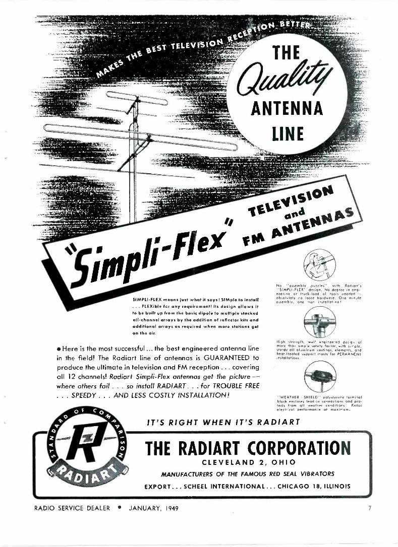
SIMPLI-FLEX means just what it says! SIMple to install ... FLEXible for any requirement! Its design allows it to be built up from the basic dipole to multiple stacked all -channel arrays by the addition of reflector kits and additional arrays as required when more stations get
on the air.
Here is the most successful ... the best engineered antenna line
in the field! The Radiart line of antennas is GUARANTEED to
produce the ultimate in television and FM reception ... covering all 12 channels! Radiart Simpli-Flex antennas get the picture - where others fail ... so install RADIART. . . for TROUBLE FREE
... SPEEDY ... AND LESS COSTLY INSTALLATION!
-wsmr...,......,.,.ro
No "assembly puzzles" with Rodiart's "SIMPLIFLEX" design. No degree in engi- neering or truck -load of tools needed - absolutely no loose hardware. One minute assembly, one man installationI
High strength, well engineered design of more than ample safety factor, with simple, sturdy all aluminum castings, elements, and heat -treated support masts for PERMANENT installations.
"WEATHER - SHIELD" polystyrene terminal block encloses lead-in connections and pro- tects from all weather conditions! Keeps electrical performance at maximum.
IT'S RIGHT WHEN IT'S RADIART
THE RADZART CORPORATION CLEVELAND 2, OHIO
MANUFACTURERS OF THE FAMOUS RED SEAL VIBRATORS
EXPORT... SCHEEL INTERNATIONAL... CHICAGO 18, ILLINOIS
RADIO SERVICE DEALER JANUARY, 1949 7

Build profits 3 ways
Controls With CRL's improved Adashaft Radiohms you can carry a small stock of controls, yet be ready
to handle almost any kind of control replacement problem. No wiggle, no wobble, no slip. Just insert shaft pilot in control stub shaft, and slip "C" washer into place. Available in all sizes for all model "M" volume control applications. Six types of shafts.
8
SSwi Centralab offers you a complete line of Tone, witches: Rotary Selector, Lever Action and Medium Duty Power Switches, which features a wide variety in both laminated phenolic and steatite insulation. Available with shorting or non - shorting contacts. See your Centralab Distributor for further in- formation, or write direct for new Catalog 26.
RADIO SERVICE DEALER JANUARY, 1949

with Centralab parts Three real advantages are yours when you use dependable CRL replacement
parts in your shop. That's the word of successful servicemen everywhere.
These men report 1. Centralab parts are easy to stock ... easy to iden-
tify. Many CRL components are packaged to give you more shelf space .. .
neater displays. All are clearly labeled for quick identification. 2. Centralab
parts are easy to use. CRL design speeds repairs by eliminating tricky bend-
ing or fitting operations. 3. Centralab parts provide performance that in-
sures repeat orders ... invites new customers. Yes - Centralab parts can
help you build up your service business. Get the complete story from your
CRL distributor. - Phil A. Smith, owner of the Smith Radio & Appliance Company, Shorewood, Wisconsin,
says, "I've been in the radio -servicing business 21 years - using Centralab replacement parts from the begin- ning. During this period I've had plenty of opportunity to prove just how dependable CRL parts are."
xx(g' // CRL line of ceramic By-pass and Coupling I1 P Capacitors gives you ceramic dependability
and perrian.ncr at a new low price! Packaged in a convenient envelope of five, Hr -Kaps are clean, easy to stock and handle. Wide range from .000050 to .010000 mfd. Rating - 600 WVDC, 1000 VDC. flash tested. Ask your Centralab Distributor for all the facts.
RADIO SERVICE DEALER JANUARY, 1949
wH1 Kaps-1/o-lf Just out! Centralab's new high volt- s P age capacitors for television and high
voltage applications. Made of Ceramic -X, Hi -Vo -Kaps combine high voltage and small size to give you convenient, dependable performance. 10,000 WVDC, flash tested. 20,000 VDC. Capacity - 500 mmf. See your CRL Distributor, or write direct.

BASIC TYPES
REPLACE OVER
Revolutionary Discovery
Simplifies Replacement-
Greatly Improves
Record Playing
MODEL M12
Med,urn Voltage
(Red)
J,,, rOpE
DA/rE ') .,,. ..
1-22A 1-765
1-25A 1-7605
L26A LT -M
1-27A LT -MA
1.J20 lT1-M
1.70 IT 1-M0
1-700 11244
L-705 LT2-MA
1-7005 L13 -M
1.71 1-1
1-71A I -M
1-71S 401-A
1-7165
1.76 1.760
P30 P93C
P308 P93D
P30C P93E
P30D P935
P30E p94
P305 P94B
P87 P94E
P87B W426
P875 W57A p908 W57AN
P90C W 58A
P90D W600
P905 W608
P93 W60H5
P93B W61B
P88
P885
P89
P895
W400 W41A
E4 N4
E4.1 N6 E-9 N6P
F1 N6P-4
F1P NB
F2 N8P
F2P N9
F3P NI1
F4P N11P
F5
F5P
F6
F6P
N2
143
94566 W590 99-180 99.181
1-240 1-725
1.360 1-7205
L -46A 1-82
1L50A L82A
L-72 1-82V
L-720 M-23 t.will OT -31A
OT -3M
OT-3/AA
1-400 LP -6
L-410 11-21
L-75 LP -23
1.750 MLP-1
1.755 MLP-I1
1-7505 MLP-2
QC
OT -1
0T -M
01-21 OT -2M
0131
STANDARD
MODELS
TONE_ ARM CARTR100'
tt CC RICHER TONE.. LESS RECORD ' . FULL BASS
WEAR LONGER RECORD
LIFE LISS SURFACE NGISE gb
EAST GER LIFE NEpLE
REPL T TO INSTALL.
CE
YOUR TONE -ARM
C-21
C-31
C-64 N-10
N -10P
N-101.1
cot F3
F7P
613
N5
617
31050' 31156' 32632' 33122' 33217' 33905' 34225' 34307' 34710' 35171' 37158' 39686'
CRIA CR2A
52
71173
70339 70338
furnished with cartridges (1/2' hole or e
plate t those marked with an
c Use
"A mounting for all replacements
except "At,' hole centers). censers)late furnished (sßí to
Side
centers).
"B" mounting P late furnished (Webstertype except
Alec Model
mounting P A" tyP
All 12 Cartridges equivalent liad -STATIC" Arm Rest Button is not supP
a carlrid9e consistent Iona lower voltage
11 is recommended that the
Needle.
H12 and L12 have Osmium-tip12-5, with volumeModlevel
be,installed. specify model M
ForNOTE: Models
For Cartridge 1, H12 -S, or 1.12-S.
ELECTRO -VOICE, INC. BUCHANAN, MICH.
Export: 13 East 40th St., New York 16,
U.S.A. Coble': Arlob
lo
Nsw Torque Drive Crystal Pickup Car- tridge achieves clean, c'ear tone definition and fidelity that are t-uly amazing! You can hear the differ- ence! Gives new life 4o every record library.
AUTHORIZED DISTRIBUTORS
EVERYWHERE
Write for Re- placement Chart Bulletin No. 746
New Model L-14 Microgroove Crystal Car- tridg e, and New Model 20 Mag- netic Cartridge for Regular or Microgroove records also available.
E -V Pol. Pend. icensed under Brush Patents.;
IT PAYS TO REPLACE WITH
5".e.ep-mrcez RADIO
FIELD FINDINGS [from, page 61
pay for all services received. For ex- ample, there is no longer any need to test tubes free of charge. The monies you receive for testing tubes during a year can be applied towards the purchase of much needed new test equipment. Test equipment wears out. When a customer asks you to test his tubes, he asks you to wear out your test equipment, and he is obligated to pay for that depreciation, not to mention your time or exper- ience.
Which brings up the new premium deal that some Columbia (long-play- ing record) distributors are pulling. Full page advertisements have been run in newspapers offering the public "absolutely free a $19.95 record player attachment with the purchase of six L -P 12" records." This sort of deal is all right for the dealers who handle Columbia records, and for the people who fall for it by buying the L -P records just to get the player attach- ments. But, when a record firm has to give away such premiums in order to sell its products, to our mind, it shows an inherent weakness in the product itself, meaning the L -P ree- ords. If the other -claims made for L -P records are bona -fide, then Colum- bia need not give away $19.95 attach- ments rio clinch sales, Ineidently, every time one of these attachments is given away it prevents a radio dealer or serviceman from making a
sale of such a unit, and, when you hit a dealer in his pocketbook you hit him where it hurts. So, its a re- sult of Columbia's premium deal, I can visualize thousands of dealers and servicemen getting sore at Colum- bia. .Losing the recomendation and good will factor of the Nation's Serv- ice Dealers is going to cost Columbia a lot more, over a period of time, than they'll get out of their premium deal.
As stated in this issue's Editorial, we are 100% for L -P records and dual speed player attachments be- cause they afford Service Dealers and technicians with a new, potential sales item that can represent a tremendous profit over a period of time. But no one can compete with give-aways, and we can only go on record that we are 100% against all sueli free offers. Let Columbia sell its line of records, and let our group of merchants be given the right to sell the attachments and the time and skill needed to install them and kep them in repair. Shame on Columbia!
SERVICE DEALER JANUARY, 1949

Form A Group. Servicemen". %ubscribe to -RS»
SAVE Up to 50%
* The more in a group the bigger the savings.
6 men in a group save $1.00 each; 4 men groups
save $ .75 per man. Present "RSD" subscribers
may participate in or form a group with co-
workers, or even competitors. Still active sub-
scriptions are automatically extended I year.
Start a Group today! The timely and exclusive
technical data appearing in future issues of
"RSD" will make this the best investment you
ever made. The special Group Rate offer may
be withdrawn at any time-so hurry.
Use This Coupon For Convenience (The coupon below can be used for from I to 6 subscription orders. Use it today!)
TEAR OUT - MAIL TODAY RADIO SERVICE -DEALER MAGAZINE In U.S.A. Foreign 342 Madison Ave., New York 17, N. Y. & Canada Rates
1-1 One I -year subscription $2.00 $3.00 Please enter I year subscription orders for the names [I] Two I -year subscriptions, each 1.75 2.75 given below. Our remittance is enclosed. Three I -year subscriptions, 1.50 2.50
NOTE: If you do not wish to tear this order blank out, just print or type the information on a single sheet of paper, following the style given. Each subscriber's occupation must be clearly described.
3 Four I -year subscriptions, Five I -year subscriptions,
13 Six I -year subscriptions,
1.25 1.10 1.00
2.25 2.00 1.50
Name
Address.
Describe Title or Position and Type of Business
State whether a New Subscriber El or Renewal Order E
Name.
Address.
Describe Title or Position and Type of Business
State whether a New Subscriber E or Renewal Order E
Name Address
Describe Title or Position and Type of Business
State whether a New Subscriber D or Renewal Order D
Name. Address
Describe Title or Position and Type of Business
State whether a New Subscriber fl or Renewal Order D
Name Address
Describe Title or Position and Type of Business
State whether a New Subscriber D or Renewal Order 12
Name Address
Describe Title or Position and Type of Business
State whether a New Subscriber D or Renewal Order o
RADIO SERVICE DEALER JANUARY, 1949 I I

TRADE FLASHES press-time- digest of production. distribution .1 merchandising astis hies
Woods Sept. Contest Winner First prize in the September Hy -
trou Servicemen's Contest was won by Casimir F. Woods of 54 North i th Street, Newark, New Jersey.
Hytron Rep. H. H. Friedman and Stanley Dudek, Radio Parts Division Manager of the Variety Electric
Company, made the prize tion, a Jackson Model 041 Signal Generator.
Mr. Woods has been associated with Colonial Radio, Buffalo. At the present. he is attending a technical school for television and plans to open Isis own business in the near future.
presenta - Uni versa l
RMA Fights Ordinances The RMA Board of Directors ap-
propriated funds and directed Gen- eral Counsel John W. Van Allen to take whatever legal action is neces- sary to bring about modification or repeal of a New York City ordin- ance restricting the use of sound equit ment and mobile radio equip- ment after it was explained that the municipal law is so broad that it bars the use of private auto radios, radio communication facilities for trucks or taxis, and aircraft and mar- itime radio facilities when operated within the confines of New York City.
Funds also were appropriated to enable Judge Van Allen to bring a
test case challenging the constitu- tionality of a Pennsylvania state tax ruling imposing a tax on taverns equipped with television receivers. The action will be brought in Fed- eral court and will contend that tele -
12
vision broadcasting is inter -state commerce and consequently 10 sub- ject to taxation by a state.
A constructive RMA program to deal xvith the problem of television antenna installations in apartment houses, proposed by the RMA Ser- vice Committee, is under considera- tion, including proposed cooperation with apartment house owners, man- agers, and the National Real Estate Board. The RMA program is de- signed to meet the needs of both apartment house tenants and owner - management interests, with master antenna systems developed under RMA auspices.
Included in the RMA program is a proposal for eooperative develop- ment by the RMA legal department with the National Real Estate Board of a standard apartment house lease covering television installations.
October Radio Tube Sales Up
October salas of radio receiving tubes by .IZ tlA member -companies totalled 19,521,368, an increase of more than one million over sales in September, the Radio Manufacturers Association reported.
A breakdown of October sales shows 14,101,695 tubes sold for new sets; 3,676,254 for replacements; 1,- 690,356 for export; and 53,063 sold to government agencies. Total re- ceiving tubes sold by RMA manu- facturers during the first 10 months of this year amounted to 164,331,340.
I.R.E. 1949 Convention The 1949 National Convention of
The Institute of Radio Engineers will be held from March 7 to 10 at the Hotel Commodore and Grand Central Palace in New York City. Radio loran, radar, and television, the big new contribution to modern living, will be thoroughly covered.
Syracuse Gets TV Syracuse, N. Y., dealers and tech-
nicians got the low-down on tele- vision during a recent meeting at General Electric's Electronics Park. Television came to Syracuse mid - Dec. when station WHEN started program tests. G.E. supplied the transmitter a n d associated equip- ment for the station.
Typifying the wide -spread interest in practical television servicing more than 300 radio service dealers reg- istered at the technical meeting Al Saunders conducted on behalf of Howard W. Sams & Co. in Dallas, Tex., in cooperation with jobbers.
Mallory Gets Citation A citation for "outstanding
achievements in human relations in labor" was awarded to P. R. Mallory
Co., Inc. at the sixth annaul Ex- ecutive Leadership Forum, sponsored by the Indianapolis Junior Chamber .,t Commerce on November 16.
Scientific TV Tube Tester SyIv;oiia research recently built
an automat recording spectroradio- uieter for precise measurement of
television viewing tube light output. Production of the instrument, which will be used in production quality control in commercial television tube production at Emporium, Pa., was under the direction of A. E. Martin. supervisor of the photonie section.
Battery Merchandiser Burgess Battery co., Freetnnt.
announces a new counter battery merchandiser which displays 14 best- selling flashlights in 5 models. These retail from 98c to $2.30. The mer- chandiser builds repeat sales and acts as its own inventory guide. For details write Burgess direct.
RADIO SERVICE DEALER JANUARY, 1949

ZgAte,W,teAd
ON INTERMITTENTS
One of the greatest single problems encountered by the radio technician in his daily work is the ir' ermittent radio set.
However, when suitable instruments are used to monitor intermittent receivers, the regular shop schedule can be maintained. Other service jobs can be completed while monitor instru- ments stand watch for any change in the func- tioning of an intermittent receiver.
Less effective methods are also used to shoot intermittent trouble. In an attempt to save man-hours, some technicians habitually replace a majority of the capacitors in an intermittent receiver at the outset. This remedy is frequently unsuccessful because many intermittents are caused by defective resistors, coils, switches, tubes, etc. Even after all of the suspected items are replaced, an appreciable percentage of receivers remain intermittent. In such cases, man-hour costs are pyramided on top of com- ponent costs; if these costs are passed on to the customer, good will suffers.
Artificial acceleration of the intermittent cycle is helpful in some cases. High line voltage will hasten the breakdown of certain marginal com- ponents. Low line voltage frequently causes a defective oscillator to cease operation. Some intermittents can be speeded up by increasing the operating temperature of the chassis by placing it in a carton with an incandescent lamp.
Although all of these methods work at times, signal -monitoring techniques have been found to be the best answer to the intermittent problem. Occasional checks of the monitor indicators show whether gradual operating changes are taking place. After the intermittent occurs, it can be localized to a particular section of the re- ceiver by analysis of the monitor instruments.
Monitoring instruments have the advantage of providing a continuous check of the oscillator frequency and voltage, of the intermediate signal frequency and amplitude, of the audio input and output, of the receiver power consumption, and of the avc supply voltage.
Oscillator frequency shift is one of the most elusive causes of intermittent operation. Other obscure intermittents are caused by defective power -supply components, which show up on the monitor chiefly as a change in power con- sumption.
t-
Monitor Instruments
Oscillator Frequency Indicator
Oscillator Voltage Indicator
Voltage indicator de!ects oscillator frequency shift
This brief discussion illustrates the important fact that many hours of time can be saved if the receiver is divided into five main sections, or channels, which can be monitored continu- ously. These are the hf oscillator, the rf or if channel, the audio system, the power supply, and the avc channel. After the intermittent has been localized to one of these sections, the instrument probes can be used to "close in" on the defective component.
Continuous monitoring places intermittent trouble -shooting on a firm technical basis.
Fib
The RCA -162-C Chanalyst Electronic Analyzer
makes the difference between profit and loss
THE RCA -162-C Chanalyst Elec- tronic Analyzer solves once and
for all the problem of time-consum- ing intermittents. It works for you unattended-and spots the fault in any receiver whenever it shows- leaving you free for other work. That's why the RCA Chanalyst more than pays for itself in the time it saves.
The RCA -162-C will give you a positive check of any fault which takes place in the receiver under test. Its four electron -ray tubes plus an electronic voltmeter give an im- mediate indication of any change when it occurs. Once the trouble is localized it is a simple matter to determine the cause.
Find out today how the RCA -162-C Chanalyst Analyzer can make more
money for you. Ask your RCA Test and Measuring Equipment Distribu- tor for the new bulletin on the 162-C, or write RCA, Commercial Engineering, Section 55AX, Harri- son, New Jersey.
SPECIFICATIONS
RF -IF Indicator Channel: Frequency Range 96 kc. to 1700 kc. Frequency Calibration ±2% Oscillator Indicator Channel: Frequency Range ... 600 kc. to 15,000 ice. Frequency Calibration ±2% AF Indicator Channel: Frequency Response 150 to 50,000 cycles
VT Voltmeter Indicator Channel: Voltage Ranges 0-5, 25, 125, 500 DC Volts Scale.. zero center with positive and nega-
tive deflection Input Impedance 11 Megohms
Wattage Indicator Channel: Input Range 30 to 250 watts
Always keep in touch with your RCA Distributor
RADIO CORPORATION of AMERICA TEST AND MEASURING EQUIPMENT' HARRISON. N. J.
RADIO SERVICE DEALER JANUARY, 1949 13
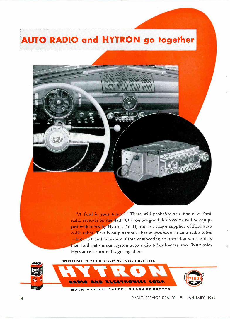
"A_ Ford in your 1 " There will probably be a fine new Ford
radie receiver on t .. ash. Chances are good this receiver will be equip-
ped with tub.-.,, ,.y, ytron. For Hytron is a major supplier of Ford auto
radio t ' " hat is only natural. Hytron specializes in auto radio tubes
T and miniature. Close engineering co-operation with leaders
I e Ford help make Hytron auto radio tubes leaders, too. 'Nuff said.
Hytron and auto radio go together.
SPECIALISTS IN RADIO RECEIVING TUBES SINCE 1921.
MAIN OFFICE: SALEM, MASSACHUSETTS
14 RADIO SERVICE DEALER JANUARY, 1949

¿?JtQckñzq
VIDEO & SYNCH WAVEFORMS
2LthzqaC#?Û
Final installment of this the nae form shapes and
THE final installment in this series deals with the practical methods that may be employed in observ-
ing the various synch and signal waveforms on a cathode ray oscil- loscope discussed in the first install- ment. Figure S illustrates a typical set-up for this purpose. When making these tests it is advisable to set up the receiver so that all test points are readily accessible.
In order to become familiar with the general procedures of these tests it is best to tune in a station pattern under normal operating conditions. A pattern of this type results in a con- stant video signal and lends itself readily to easy interpretation. Initial Test Point
The most convenient initial point of measurement is the output of the second detector. The reason for this choice is that the signal voltage at this point is 1 or 2 volts, and lends itself to good observations on an oscil- loscope. Remember that we are pri- marily concerned with measuring and observing the video picture signal and the synch pulses, and that these are first observable in their demodu- lated forms at the output of the second detector.
Figure 9 at the top right illus- trates a combined video signal and vertical synch pulse obtained at the detector output. The sweep frequency of the ORO has been set at 30 cycles
by SAMUEL M AR SHH.AL.L.
PART 2
series. Actual test sel -ups are illustrated. together w ilh amplitudes that might he expected a Iapical TV receiver
Fig. 8-Television Assembly Champion Model and Sylvania CRO used in tests.
in order to permit two of these pulses to appear on the screen. The partial circuit diagram on the left illustrates the test points for this test. This corresponds to point E on the block diagram section discussed during the first installment. See Fig. 1. The com- plete front view of the cathode ray oscilloscope with all its settings, and the waveform appearing on the screen is at the top right.
To make this test a connection is made between the detector output and
the vertical input connection on the CRO. Another connection is then made between the ground connections of the receiver and the oscilloscope. The detector output connection may be taken off at either side of the coupling condenser, C, whichever is most convenient. The receiver output is adjusted to its optimum level, thereby requiring a minimum setting of the vertical gain control on the scope. This will result in more ac- curate and satisfactory patterns.
RADIO SERVICE DEALER JANUARY, 1949 15

TEST POINTS I \
I
I
Notice the amplitude A of the com- bined synch pulse and signal as com- pared with the signal amplitude it- self shown as ]i. Tice middle line at 11, represents the blanking level, and the height above this level-(in the slide this occurs below the blacking level because of the reversed phase of the patternl-is the region called "blacker -than -black."
The blanking level should he 75% of tice total height, A, according to FCC standards.
Shown in the lower right hand side of this illustration are the horizontal synch pulses and the associated pic- ture signal. The same test point is used. However, the sweep frequency of the CRO is now adjusted to one-- half the incoming horizontal synch pulse frequency. This is 15,750 divided by 2, or 7.875 cycles.
Figicn' 10 shows the vertical and horizontal pulses at the output of the first video amplifier. Notice that the phase has been reversed 180° which is characteristic of vacuum tube action. The amplitude of the signal at t his point is about 16 volts. Vary- ing the gain of the receiver by means of the contrast control will produce corresponding variations in the height of the pattern.
As in the previous test, the sweep of the CRO is adjusted to portray two pulses. The test point may be
6AU6 I st. VIDEO
AMP.
6K6 VIDEO
OUTPUT
+ 435 V. +285 V. - 20 V.
PARTIAL SCHEMATIC OF CIRCUIT UNDER TEST
p-- DET.
TEST POINT
I st. VIDEO AMP.
VIDEO
OUTPUT
0 -O
PARTIAL BLOCK DIAGRAM
TEST POINTS I I
1 6AU6 I st. VIDEO
AMP.
, O
-2V.
PARTIAL SCHEMATIC OF CIRCUIT UNDER TEST
TEST POINT
I 0 I
0- VIDEO OET
VIDEO
1.F. AMP. O
PARTIAL BLACK DIAGRAM
VERT. SYNCH PULSE
HOR. SYNCH PULSE
Blacker thon block
Fig. 9-Waveforms, horizontal and vertical obtained at detector output.
made on either side of the coupling condenser, C, shown in the partial schematic at the left of the slide. The probe connection of the scope may be brought to the plate side of the coup -
VERT. SYNCH PULSE
HOR. SYNCH PULSE
Fig. 10-Horizontal and vertical pulses obtained at 1st video amplifier.
ling condenser if all isolating con- denser is located in series with the vertical input terminal; and it usual- ly is.
Proceeding now to the output of the final video stage, as shown in Fig. 11, we notice that the phase for both horizontal and vertical plates is main reversed, and that the ampli- tudes of the signal are considerably increased. Ill this case it is 45 volts. This output is fed directly into the ;rid of the CRT, and as previously pointed ont, represents a positive Picture phase.
Synch Circuit Section .1 portion of the video signal is
taken off the cl -c restorer at the GALS plate connection No. 2. The signal at this point, containing both video and synch components, with the video somewhat reduced, is fed into the first synch amplifier at a negative synch iliase, or what amounts to the saine thing, a positive picture phase.
This is shown in Fig. 12. The operat- ing characteristics of this circuit result in a reduction of pulses due to noise and other interfering signals. The amplitude of the signal at the grid of the first, synch amplifier is about one-fourth that of the output at the plate of the final video ampli- fier. This is due to the signal being taken off a point on a voltage divider connected across this circuit.
16 RADIO SERVICE DEALER JANUARY, 1949
6K6 VIDEO
OUTPUT
+135V
TEST POINTS
6AL5 D.C.
RESTORER
TO FIRST SYNCH AMP.
PARTIAL SCHEMATIC OF CIRCUIT UNDER TEST
VERT_ SYNCH PULSE
HOR. SYNCH PULSE
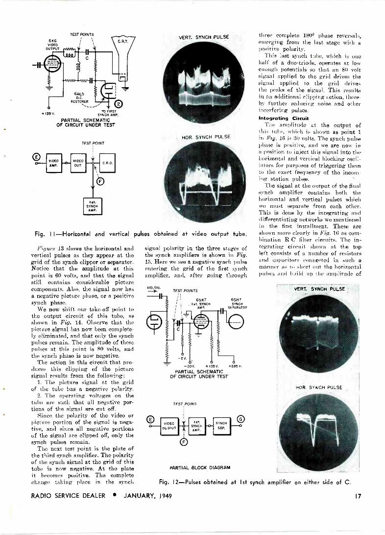
Fig. II -Horizontal and vertical pulses obtained at video output tube.
Figure 13 shows the horizontal and vertical pulses as they appear at the grid of the synch clipper or separator. Notice that the amplitude at this point is 60 volts, and that the signal still contains considerable picture components. Also, the signal now has a negative picture phase, or a positive synch phase.
We now shift our take-off point to the output circuit of this tube, as shown in Fig. 14. Observe that the picture signal has now been complete- ly eliminated, and that only the synch pulses remain. The amplitude of these pulses at this point is 80 volts, and the synch phase is now negative.
The action in this circuit that pro- duces this clipping of the picture signal results from the following:
1. The picture signal at the grid of the tube has a negative polarity.
2. The operating voltages on the tube are such that all negative por- tions of the signal are cut off.
Since the polarity of the video or picture portion of the signal is nega- tive, and since all negative portions of the signal are clipped off, only the synch pulses remain.
The next test point is the plate of the third synch amplifier. The polarity of the synch signal at the grid of this tube is now negative. At the plate it becomes positive. The complete change taking place in the synch
signal polarity in the three stages of the synch amplifiers is shown in Fig. 15. Here we see a negative synch pulse entering the grid of the first synch amplifier, and, after going through
VID. SIG. TEST POINTS
6SK7 1st, SYNCH
AMP.
-2V.
6SH7 SYNCH
SEPARATOR
-20V +135V. +285 V.
PARTIAL SCHEMATIC OF CIRCUIT UNDER TEST
TEST POINT
VIDEO OUTPUT
1st. SYNCH AMP.
SYNCH
SEP.
PARTIAL BLOCK DIAGRAM
three complete 180° phase reversals, emerging from the last stage with a positive polarity.
This last synch tube, which is one half of a duo -triode, operates at low enough potentials so that an 80 volt signal applied to the grid drives the signal applied to the grid drives the peaks of the signal. This results in an additional clipping action, there- by further reducing noise and other interfering pulses. Integrating Circuit
The amplitude at the output of this tube, which is shown as point 1 in Fig. 16 is 30 volts. The synch pulse phase is positive, and we are now in a position to inject this signal into the horizontal and vertical blocking oscil- lators for purposes of triggering them to the exact frequency of the incom- ing station pulses.
The signal at the output of the final synch amplifier contains both the horizontal and vertical pulses which we must separate from each other. This is done by the integrating and differentiating networks we mentioned in the first installment. These are shown more clearly in Fig. 16 as com- bination R -C filter circuits. The in- tegrating circuit shown at the top left consists of a number of resistors and capacitors connected in such a manner as to short out the horizontal pulses and build up the amplitude of
Fig. 12-Pulses obtained at Ist synch amplifier
RADIO SERVICE DEALER JANUARY, 1949
VERT. SYNCH PULSE
NOR. SYNCH PULSE
on either side of C.
I7

TEST POINTS I
I
6SH7 SYNCH
SEP.
+135V.
+285V -2V. -20V.
1/2 6SN7 SYNCH
AMP.
PARTIAL SCHEMATIC OF CIRCUIT UNDER TEST
TEST POINT
0 F 1sC. SYNCH (")- SYNCH
SEP. AMP.
SYNCH AMP.
PARTIAL BLOCK DIAGRAM
Fig. 13-Pulses obtained at input of
the vertical pulses. Notice the shunt capacitors, Ci, 02, and Cs. These con- densers in addition to building up the amplitude of the vertical synch signal during successive pulses of the ser- rated vertical synch ,pulse, short out the higher frequency horizontal pulses, leaving only the vertical pulse to reach the grid of the 635 vertical oscillator.
Proceeding now to the differenti- ating circuit, the 100 mmf condenser connecting the output of the third synch amplifier to the input of the horizontal oscillator presents a high reactance to the low frequency vertical pulses as compared to high frequency horizontal pulses, so that the signal permitted to pass thru this condenser contains only the horizontal pulses.
If we apply the test probe of the CRO to point 1, both the vertical and the horizontal pulses appear. At point 2 only the vertical pulses ap- pear, and at point 3 only the hori- zontal pulses appear.
We are now ready to trace the verti- cal pulses as they proceed from the output of the 6J5 oscillator to the input of the vertical deflecting coils. The lower left-hand portion of Fig. 17 is"devoted to the block diagram of this portion of the circuit.
The upper left-hand portion of the figure is confined to a simplified partial schematic of this circuit. The
18
VERT. SYNCH PULSE
HOR. SYNCH PULSE
6SH7 synch separater. Note waveforms.
four test points shown in the block diagram are indicated in the partial schematic by identical numbers. Thus :
No. 1 is the input of the vertical oscillator.
6SH7 SYNCH
SEP.
TEST POINTS
I I
1 ,
1 ,
1 , 1 ,
SYNCH SEP
C
1/e 6SN7 3rd. SYNCH
AMP.
+ 135V.
TO VERTICAL NETWORK
TO HORIZONTAL
NETWORK
PARTIAL SCHEMATIC OF CIRCUIT UNDER TEST
VERT NET.
3rd. SYNCH
AMP.
PARTIAL BLOCK DIAGRAM
Fig. 14-Horizontal and vertical pulses obtained at 3rd synch amp. input.
No. 2 is the output of the vertical oscillator, the amplitude of which is about 120 volts. This signal is acted upon by the discharge or peaking cir- cuit. The object of this circuit is to obtain a wave at the output of the oscillator which insures the presence of a sawtooth current wave in the vertical deflecting coils. But, more on that shortly.
No. 3 is the output of the vertical deflecting coils. The potential at this point is about 65 volts.
No. 4 is the input to the vertical output tube, which is about 450 volts.
The corresponding waveforms for test points 1, 2, 3, and 4 are shown at the right of the screen.
No. 1 proceeding from top to bot- tom indicates the sharp steep dis- charge, and slow saw -tooth charge portions of the wave which are charac- teristic of the blocking oscillator.
No. 2 indicates the effect of the peaking, or discharge circuit on this waveform. Variations of this wave- form may be produced by varying the vertical amplitude control. This is an excellent check on the operation of this circuit.
No. 3 indicates the waveform of the pulse at the plate of the vertical output tube, or the 6Iï6. Notice how high the pulse voltage is for the re- trace portion. This is necessary to insure a high retrace current rate on
HOR. SYNCH PULSE
RADIO SERVICE DEALER JANUARY, 1949

the vertical deflecting coils during the retrace period. Peaking
The reader will recall, the formula relating to voltage, inductance, and the rate of change of current in coil given in the first installment. This formula is repeated again in two forms:
e = L x Rate of change of current Rate of change of current = e/L During the retrace period the fre-
quency is much higher than the 60 cycle frequency of the trace period. As a result, the reactance set up by the inductance in the coil is much higher than before. This affects the current considerably. From the formu-
" la shown above, in order to get a high and fast discharge of current during the retrace period the voltage ampli- tude must be high and its waveform steep.
Returning again to Fig. 17, and ex- amining waveform No. 4 once again, we notice that the trace portion of the voltage curve is somewhat of a sawtooth. This is due to the fact that during the trace period, the induc- tance of the vertical deflecting coil is negligible as compared to its re- sistance. In a resistance, if we want a
saw -tooth current we must have a saw -tooth voltage. This explains why, in the composite wave, the waveform of the retrace is a sharp high ampli -
1/2 6SN7 3 rd. SYNCH
AMP.
;y
+ 135V
3rd. SYNCH
AMP.
TEST POINTS
/ y
pool
YNf -110V.
VERT.-' -100 V.
TEST _POINT r
HOLD. CONT.
r0oo 1
HORIZ. 6SN7 HOLD. CONT. HORIZ. OSC.
PARTIAL SCHEMATIC OF CIRCUIT UNDER TEST
VERTICAL INTEG.
NETWORK
HORIZ. DIFFER EN. NETWORK
VERT OSC.
HOR.
QSC.
PARTIAL BLOCK DIAGRAM
Fig. 16-Waveforms obtained at horizontal and vertical separation
RADIO SERVICE DEALER JANUARY, 1949
NEGATIVE SYNCH
SIGNAL
1eo
Ist. SYNCH
AMPLIFIER
POSITIVE SYNCH
SIGNAL
SYNCH SEPARATOR
OR CLIPPER
NEGATIVE SYNCH
SIGNAL
leo
FINAL SYNCH
AMPLIFIER
POSITIVE SYNCH
SIGNAL
SYNCH SIGNAL PHASE REVERSALS IN SYNCH AMPLIFIER SECTION
Fig. 15-Signal phase is reversed 180° as it passes through each tube.
tude pulse, and the waveform of the No. 1 is the input of the horizontal trace is a low amplitude saw -tooth. oscillator.
No. 2 is the output of the hori- zontal oscillator, at about 120 volts.
We can now proceed to the hori- No. 3 is the output of the hori- zontal oscillator and the circuits de- zontal discharge circuit, at about 45 voted to the development of the hori- volts. zontal sweep. Fig. 18 illustrates the No. 4 is the output of the hori- partial schematic of this portion of zontal output tube, at about 4,000 the circuit in the upper left portion of volts. The utmost caution should be the screen. Below it is the block dia- used when measuring high voltages gram showing the test points num- of this nature. bered to correspond to the same points No. 5 is the output of the hori- in the schematic above. These test zontal output transformer, which is points are as follows: about 800 volts, and represents the
voltage waveform appearing across the horizontal deflecting coils. Notice the flattop characteristic of this wave- form. It will be recalled that in order to obtain a sawtooth current wave in a circuit which is predominantly inductive, a flattop voltage wave is required. When measuring these high voltages a high voltage test probe should be used, and a capacitance volt- age divider should be employed for the ORO to prevent damage to its input circuit.
Space does not permit further analysis of the many fine points each
[Continued on page 47]
Horizontal Circuit
VERT. SYNCH PULSE
HOR. SYNCH PULSE
points.
$1.00 to $5.00 PAID
for "SHOP NOTES" Write up any "kinks" or "tricks -of -
the -trade" in radio servicing that you have discovered. We will pay from $I to $5 for such previously unpublished "SHOP NOTES" found acceptable. Send your data to "Shop Notes Editor," RADIO SERVICE DEALER, 342 Madison Ave., New York 17, N. Y. Unused manu- scripts cannot be returned unless accom- panied by stamped and addressed re- turn envelope.
19

jkQQdbLIJh
PHASE Dl RING our chores as servicemen and dealers we necessarily deal
with feedback and phase inversion within audio amplifiers to a great- er extent than we realize. It is there- fore fitting that we thoroughly under- stand these associated subjects. It is important to remember that, careless replacement of some critical capacitor, resistor or inductance by one not hav- ing the identical value intended for the original, will cause phase shift dis- tortion. The effect becomes cumula- tive when several careless replace- ments are made with the direct result that the original signal becomes con- siderably distorted.
In multistage amplifiers care must be taken to prevent unwanted feed- back of signal voltage in the output stage from getting back into the in- put circuits. Should such feedback occur, the signal fed back may be of such phase relation as to either aid or oppose the original input signal. Feedback of an aiding nature is called positive or regenerative while that which opposes the input signal, that which is out of phase with it, is called negative, degenerative, or inverse feedback. When properly controlled the negative type can prove most use- ful; in fact is used to great advantage in modern audio amplifiers. More on that later.
Fig. I-Tickler feedback.
20
F.ffecls of feedback. positive and negatixe, and principles and applications of phase inversion are discussed in two articles. the first of which is presented in this issue. r
Positive Feedback
Positive feedback has the same phase relation as the original signal; their positive half cycles are synchro- nized in time or phase relation with each other as are the negative half cycles. Such feedback was deliberately introduced in earlier regenerative sets where a tickler coil in series with the detector plate circuit was deliberately fed back to the preceding grid circuit
R1
R2
V2
abe V3
Fig. 2-Diode detector feedback.
in phase for an increase of signal strength. (See Fig. 1). However, be- cause of its unstable character this regenerative type of feedback is sel- dom intentional in amplifiers. More often in the servicing of amplifiers it is to be eliminated or at least held to a minimum. Therefore we list the following reasons which may cause its unintentional occurrence:
1. Inductive leakage coupling; in- sufficient shielding between inputs and outputs; lack of decoupling; coils too close together or not at right angles to each other.
Fig. 5-Block schematic principles
2. Linkage of inputs and outputs through the use of common grounds or common power supplies. Plate and screen a -c currents must not flow through a common positive supply to all tubes. Filtering will correct this.
3. A shorted by-pass or shorted de - coupling filter condenser will conduct positive feedback from output to in- put or supply circuits.
Phase Inversion Example 1-For one of the simpl-
est examples of phase inversion, refer back to Fig. 1 to the regenerative tick- ler coil discussed under Positive Feed- back. When the tickler's magnetic flux cuts across the preceding grid coil in such a manner as to induce voltages which are in agreement or of the same polarity as that of the in- coming signal, the coupled voltages are in phase. When the leads or ends of such a tickler coil are reversed, while it remains in the same physical relation, it's phase becomes inverted. The two voltages oppose each other and the original positive feedback becomes inverted to negative feed- back.
RADIO SERVICE DEALER JANUARY. 1949
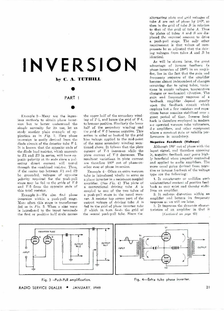
INVERSION by C. A. TUTHILL
PART I
Example 2-Many are the ingen- ious methods to obtain phase inver- sion but to better understand the simple necessity for its use, let us study another plain example of ap- pication as in Fig. 2. Here phase inversion is easily derived from the diode circuit of the detector tube V-1. It is known that the opposite ends of the diode load resistor, which amounts to R1 and R2 in series, will have op- posite polarity at its ends since a pul- sating direct current will travel through the combined resistor. Then, if the center tap between RI and R2 be grounded, voltages of opposite polarity required for the push-pull stage may be fed to the grids of V-2 and V-3 from the opposite ends of this total resistor.
Example 3-We also find phase inversion within a push-pull stage. More often this stage is transformer fed as in Fig. 3. 'When a sine wave is introduced to the input terminals the first or positive half cycle causes
the upper half of the secondary wind- ing of T-1, and hence the grid of V-1, to become positive. Similarly the lower half of the secondary winding and the grid of V-2 become negative. This action is aided or bucked by the grid bias voltage applied to the mid -point of the same secondary winding men- tioned above. It follows that the plate current of V-1 increases while the plate current of V-2 decreases. The resultant variations in plate current are therefore 180° out of phase -an- other case of phase inversion.
Example 4-Often an extra vacuum tube is introduced wholly to serve as a phase inverter in a resistance coupled amplifier. (See Fig. 4) The plate of a conventional driving tube A is coupled to one of the two tubes of a push-pull stage in the usual man- ner. A resistor tap across part of the output voltage of driving tube A is fed to the grid of phase inverter tube B which in turn feeds the grid of
the second push-pull tube. Since the
Fig. 3-Push-Pull amplification.
RADIO SERVICE DEALER JANUARY, 1949
alternating plate and grid voltages of tube A are out of phase by 180°, so then is the grid of tube B in relation to that of the grid of tube A. Thus the plates of tubes A and B are dis- placed the required amount to drive a push-pull stage. The only other requirement is that values of com- ponents be so adjusted that the driv- ing voltages from tubes A and B be identical.
As will be shown later, the great advantage of inverse feedback (a phase inversion of 180°) in an ampli- fier, lies in the fact that the gain and frequency response of the amplifier become almost independent of changes occurring due to aging tubes, varia- tions in supply voltages, temperature changes or mechanical vibration. The gain and frequency response of a feedback amplifier depend greatly upon the feedback circuit which employs but a few resistors and capa- citors hence remains stabilized over a great period of time. Inverse feed- back is therefore employed in modern a -c operated vacuum tube voltmeters, d -c amplifiers, and other equipment where a constant gain or reliable per- formance is mandatory.
Negative Feedback (Voltage) Although 180° out of phase with the
input signal, and therefore opposing it, negative feedback may prove high- ly beneficial when properly controlled and applied to audio amplifiers. The more usual gains derived from nega- tive or inverse feedback of the voltage type are the following:
1. It counteracts or nullifies such unintentional content of positive feed- back as may exist and thereby stabi- lizes an amplifier.
2. It reduces distortion within an amplifier and betters its frequency response as we will see later.
3. It improves the dynamic charac- teristics of an amplifier in that it
[Continued on page 45]
Fig. 4-Extra tube phase inverter.
21

SIMPLICITY and compactness very often make it advisable to
use a half -wave transformerless power supply (either tube or selenium recti- fier) in a small amplifier, tuner,: -or test instrument. The a -c hum nuis- ance caused by this type of power supply is well known.
A positive way to clean up the power supply hum arising from a half -wave transformerless unit is to employ a tuned filter section in con- junction with a simple conventional section. This arrangement is shown in Fig. 1. The tuned section is designed for elimination of the 60 -cycle ripple, and the untuned section takes care of the hum harmonics (120 cycles and upward). The L and C values in the conventional section, shown after the tuned section in Fig. 1, are not critical and can be any choke and high -capacitance capacitor the builder happens to have on hand. The tuned section, however, requires critical circuit values for optimum perform- ance at the fundamental hum fre- quency.
Including a tuned section in the power supply filter at the time of construction will require very little additional work and will pay off hand- somely in subsequent hum -free opera- tion. In order to spare the reader considerable mathematical labor, we present in this article all values which components must have in the four types of tuned filters described.
Tuned Filter Types The four types of tuned filters
which are applied most easily to trans-
+
INPUT FROM
RECTIFIER OUTPUT
T See Table I for L and C values
SERIES -TUNED SECTION
Fig. 2-Series-Tuned section.
22
TUNED Tuned filters for transformerless hall -war power supplies is the subject of this article. Various types are discussed.
INPUT FROM RECTIFIER
//4 TUNED %// SECTION
OUTPUT
BASIC ARRANGEMENT OF FILTER WITH TUNED SECTION FOLLOWED BY SIMPLE UNTUNED SECTION
Fig. I-Basic arrangement of filter with tuned section followed untuned section.
formerless half -wave rectifiers are the series -tuned type (Fig. 2), parallel - tuned type (Fig. 3), bridged -T type (Fig. 4), and parallel -T type (Fig. 5).
These types are equally effective in hum elimination, but the special features of one type may better suit it to a particular application than another type. For axample: the series - tuned type (Fig. 2) offers a very low - impedance path for the ripple current. In effect, it bypasses the ripple to ground. The parallel -tuned type (Fig. 3) offers high impedance to the rip- ple current and so "traps" it out of the power supply output.
In the parallel -tuned type, the total d -c current taken by the load circuit must pass through the tuned choke, L. If a sufficiently heavy choke is not available, therefore, the builder probably will prefer the series -tuned type in which the load current does not flow through the choke. The L and C values will be the same in each case. The rheostat, R, in the bridged - T section (Fig. 4) permits very close "tuning -out" of hum. But in this circuit also, the choke, L, must be rated to handle the full d -c load cur- rent of the power supply and the cir- cuit is somewhat more complicated by its requirement of two capacitors and a variable resistor.
The parallel -T circuit (Fig. 5) is particularly useful when a second
by simple
iron -cored choke is undesirable. Here, the hum may be tuned -out very closely by adjustment of rheostat R1.
Series -Tuned Section Any available choke may be used in
the serie --tuned section shown in Fig. 2. Table 1 lists the inductance values of chokes supplied by various manu- facturers and gives the corresponding capacitance required for resonance at 60 cycles.
It will be noted that the capac- itances all are fractional values. Se- curing these values will entail no hardship, however, since they may be obtained by connecting appropriate capacitances in parallel. Thus, the 1.6- microfarad value required to tune a 4.4 -henry choke may be obtained by connecting a 1.0-, 0.5-, and 0.1-ufd. capacitor in parallel. Some deviation from the required capacitance values given in Table 1 will be caused by manufacturing variations in choke inductances. The builder should start with a capacitance somewhat lower than the value given in the table and should connect smaller capacitances progressively in parallel, while listen- ing for satisfactory reduction of the
^rn level. Parallel -Tuned Section
The parallel -tuned section (See Fig. 3) uses the same values of capac- itance for a given inductance as the series -tuned section previously de -
RADIO SERVICE DEALER JANUARY, 1949

FILTERS by RUFUS P. TURNER
L
' 606Ö60
INPUT FROM OUTPUT
RECTIFIER
See Table I for L and C values
PARALLEL -TUNED SECTION
Fig. 3 -Parallel -Tuned section.
scribed. Select the capacitance values from Table 1, and proceed with close adjustment of the final capacitance according to the instructions given for the series -tuned circuit. Choke L must be rated to carry the full d -c load curren'.
Bridged -T Section
Two identical capacitors, Ci and C2, are required in this type of tuned filter section, shown in Fig. 4. Their values, for a given choke inductance, are obtained from Table 2. These capacitors may be matched closely enough by means of a service -type meter. Choke L must be rated to carry capacitance bridge or microfared
TABLE 1.
L ( lienries) C (microfarads) 4.4 1.600 4.5 1.565 5.0 1.410 5.5 1.280 6.5 1.082 7.0 1.008 7.5 0.939 8.0 0.880 9.0 0.783
10.0 0.704 11.0 0.640 12.0 0.587 12.5 0.564 13.0 0.541 14.0 0.503 14.5 0.486 15.0 0.470 14.0 0.392 20.0 0.352 23.0 0.306 25.0 0.282 30.0 0.235 31.0 0.227 40.0 0.176 50.0 0.141
the full d -c load current. Rheostat R
INPUT FROM
RECTIFIER
Cl
L
606000
1000 Ohm 10 Wait Rheostat
OUTPUT
See Table 2 for L and C values
BRIDGED -T TUNED SECTION
Fig. 5 -Parallel -T resistance capacitance tuned section.
RADIO SERVICE DEALER JANUARY, 1949
TABLE 2.
L (henries) C'1.C2 (microfarads) 4.4 3.160 4.5 3.085 5.(1 2.780 5.5 2.522 6.5 2.140 7.0 1.985 7.5 1.850 4.n 1.735 9.0 1.542
10.0 1.390 11.0 1.263 12.0 1.158 12.5 1.110 13.0 1.070 14.0 0.991 14.5 0.957 15.0 0.926 18.0 0.772 20.0 0.694 23.0 0.604 25.0 0.555 30.0 0.463 31.0 0.448 40.0 0.347 50.0 0.278
may be provided with a slotted shaft for screwdriver adjustment, and is "tuned" for complete hum elimina- tion.
Parollei-T Section In the parallel -T R -C tuned circuit
(See Fig. 5), the constants have been [Continued on page 44]
INPUT FROM
RECTIFIER
C, C2
8.0 Mid. 8.0 Mfd.
R3 166 Ohms 10 Watts
5'00 Ohm 25 Watt Rheostat
R2
332 Ohms 10 Waits
T16.0 Mfid.
OUTPUT
PARALLEL -T RESISTANCE -CAPACITANCE TUNED SECTION
Fig. 4 -Bridged -T tuned section.
23

á9liw PHONO PICKUP
ANEW discovery has been made which should have great ef-
fects upon the pickup manufacturing industry, and other allied industries such as hearing aids, loudspeakers etc. It is a new pickup cartridge con- taining the first man-made material acquiring the necessary pj.ezo-elec- trical properties for proper sound re- production. Piezo-electriciy is the name applied to that branch of science dealing with the conversion of mechanical pressure into electric- al power.
Properties of Titanate
The material employed in the man- ufacture of this new pickup cart- ridge is a ceramaic called, "titanate," which, when properly processed, ac- quires all the qualities necessary for good record reproduction. The first research, as pointed out by the manu- facturer, in the field of ceramics in the audio field was undertaken in conjunction with a program of re- search for hearing aids started sev- eral years ago. At that time the dis- covery was made showing that this ceramic was suitable, in some cases, in uses involving piezo-electrical properties. The more the material was studied the more advantageous it was found. Research engineers fol- lowed the lead and have completed development and consumer tests of the first news in pickup design and pickup production since the develop- ment of the crystal.
Titanate in its heitial state does not possess all the properties which would make it usable for pickup manufacturing. These properties are acquired by putting 5t through a relatively simple but precise process. The material is first mixed into a
b. lll <1 LP11 M. 11.11I lTl'11
The characteristics of a new type of phono cartridge made
of titanate, a piezo-electric ceramic, are discussed here.
20
.. .. ... Mffl.. . ffl3MI....... .MD_ .. ..fflf1. MIMI.. .__.......flf1.. .. IIMI .. .._v oc.a... ..... . ..... fIf. .. ..fM...flt1... ._tM.... ..f/ ue. .. .. .....t.... .__f1....... MIM .... u.e ...1.1 ....\.G_ .. .. ... -...«T.1.. L.-_TTT. .. ..If>f>f1......ff... Mflf1.......f1M.... ..1 n.t ... 2.0 T+Y1rH AM. .. ...ro._.i_.n.u.,t - ...f........ ......
MM .i ..------- - -_ .. ---" ffl.........f. ..... ..
R 0 5 Meg ..f.....mm.. m .....im....flf.... IMMI._--.MMI.. .f>f1 ...,. i .. uMftr..._.MM
M .,tMu.. ..1::::::CC:.:O:::,'9: .... .131111.-o.u__ mf>f1 C I__ ..... ... .ii . f.. =........ W: . .. ffl._
0 dbxe 8 Volt v.Mw ii .....MM.... .......MM... 11.e131M i...,. .... MIR __ M ..00.fflale..o iiiiiii__i ii...l n_ lI Iffl SONOTONE
( ... ... ..MMIMI. .. __MM. ...__M..
iii__Mii à Average umbia
curves test
UI CARTRIDGE M.11.... ..ii n ug Co record .. MM
M... wM.. _ _ iiiiiii No 10004 M iiumm lMIMI BM .... BM ..M.. . .. .. _.......MIf1... ..IIMMf1...111113 ...MMI ...__ ::. . .:: I:: .. BII. Ran« M.I . . H... .. 11111
..T.us. .. .. .. .fflI_f1flfl I...... N MMIMM IBM, . f1ffl MUM . IMI ... ...--...
40 100 500 1000
FREQUENCY IN CYCLES PER SECOND 5000 10 000
Fig. 2-Frequency response curves of Titone cartridge for various values of R.
heavy paste, spread on a moving belt, and conducted through a furnace where it is baked and thereby ac- quires great rigidity and hardness. The result is a long strip of material, about one hundredth of an inch thick, which is subsequently cut to,
2 o
12
the proper size. Then each piece is silvered on both sides. Two of these small slabs are put together and a saphire point attached 'through an arm at an end. The whole is encased in a metal container and equipped with screw holes for mounting. The
J
Fig. 3-Top view of cartridge and adapter.
7 8
24 RADIO SERVICE DEALER JANUARY, 1949

Fig. I-Size comparison between rec- ord and cartridge.
complete cartridge assembly is said to weigh only slightly more than two thirds of an ounce. See Fig. 1.
Properties of Pickup Features of this new pickup cart-
ridge are: Wide frequency response - high signal output- high capacitance cartridge- high needlepoint compli- ance- saphire needle point- low needle point pressure- excellent temperature and humidity resistance- small size - needle guard- low distortion- com- pactness.
The frequency response of the "Ti - tone" pickup is said to range from 50 cycles to at least 10.000 cycles. In the graph shown in Fig. 2 the frequency response can be seen as taken with the Columbia test record #10004-M. The solid line shows the output when loaded with 0.5 meg- ohms; the broken line represents the output when operating into 2 meg- ohms; the dash and dot line rep- resents the open circuit voltage.
The latter shows excellent displace- ment properties over its entire freq- uency spectrum. It must be remem- bered that good pickup frequency response can only be judged with amplification systems and loudspeak- er reproducing units able to re- produce the frequencies that are to be tested. You cannot get something reproduced from a record by a pick- up, which cannot be handled by the amplifier or the speaker. Therefore make sure that both are up to par in frequency response with the pick- up to be tested.
The generated voltage of the pick- up cartridge is sufficient in amplitude to drive the average audio frequency amplifier. A value of 0.5 volt is gen- erated at 1000 cycles per second on
the Columbia test record 10004-M. On frequencies below 1000 cycles, the open -circuit voltage generated i s directly proportional to the amplitude of the recording.
The nominal capacitance is such that the new ceramic pickup can be mounted directly into apparatus con- structed to handle the conventional Rochelle salt crystal thereby replac- ing the old type crystal. The value of this nominal capacitance is 10(10
mmfd.
Properties of Needle
A very important factor in the development of pickups is the needle point impedance, or the sensitivity of the needle to side motions and its resistance to it. The parts in most pickups are springy and move in ac- cordance with the sound picked up by the needle. This needle, and par- ticularly its point, is a very small object and is thrown back and forth between five and fifteen thiousand times per second according to the frequency reproduced. In the pickup discussed, the claimed lateral needle compliance is approximately 0.5 x 10-e cm. per dyne. and the effective moving mass is said to be very small.
The heavier or larger the moving mass the faster the record grooves will be worn out by the back and forth movement of the needle point. A small moving mass therefore would give the advantage of low record wear. The vertical needle compliance of the arm and pickup is of the order of 1.5 x 10⁻⁶ centimeters per dyne. This would allow the arm to move freely up and down when records are warped and thereby eliminate any loss of fidelity sometimes caused with other pickups by this warpage. This fact would also contribute to lower record wear. Needle talk, similarily, is said to be greatly minimized in this new pickup. Records could con- sequently be payed in open type cabinets without surface noise or needle noise, both of which are some- times so annoying.
The needle point contained in the cartridge is a permanent sapphire point. Both the needle point radius
Fig. 4-Side view needle guard removed.
and the cone angle, two other factors important for low record wear, are said to be held to rigid tolerances thereby also assuring good reproduc- tion in all frequency ranges. The cartridge was designed to 'operate with a needle point pressure of 22 grams. Temperature Characteristics
The Titone pickup is made, in part, from a form of transducer element quite different from the piezo electrical crystals such as Rochelle salt or ammonium phosphate used in the conventional pickups. The new elements introduced are said to be able to withstand temperatures ranging from -65 degrees Fahrenheit to +200 degrees without suffering any permanent damage. This should have far reaching effects in regions of this country or abroad where ex- treme climatic conditions prevail. It is the damping material used in the manufacturing of the cartridge which actually limits the temper- atures that can be withstood by the pickup.
In some tests made previously, the cartridge was immersed in a glass of hot water, installed in an ordinary pickup arm and reproduced many (lises without any apparent damage suffered by the cartridge of the records. It should be borne in mind that this heat resistance can be an important asset when the case arises where the record player or the com- bination amplifiers generate a great (leal of heat.
The weight of the cartridge has been reduced to 15 grams and because of its small size allows for construc- tion of pickup arms having graceful shapes and designs. Figs. 3 and 4 illustrate top and side views of the cartridge. A novel arrangement pro- viding a needle guard is included. In this particular cartridge a force of three ounces is enough to cause the needle guard to touch the record. The guard was installed with suffi- cient width to bridge the lands of successive grooves. The pickup car- tridge is also provided with easy to use compact tip sockets of rugged construction eliminating the need of soldering in places sometimes hard to reach. This will faciliate faster installations and replacements of the cartridge. Installation
Here are some of the installation instructions and suggestions as given by the manufacturer:
[Continued on page 42]
RADIO SERVICE DEALER JANUARY, 1949 25
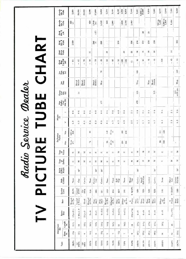
I
el
- ad
(4812
W CCI
Il
a n 0
QZ> E 25
N Ñ
S Ñ
Ñ Ó ci 25 M
S Ó
25 d
S O
ó N
S O
O S S0 or"
S, a0
§ O
S e
§ N
§ N
25 P
Z% m- 88 ? B
.
p `y0
8 O 8 d
w8 Sw ti
H
Me Z D -HÑ Ñ mA Z QX
8 N~ Ñ Ñ Ñ Ñ Ñ Ñ VOf
`1 i
>= I V;
e, co M
O M
V) Cl
O M ?^0 .. M M
-010- 31.v0
J 1
b 1
N
I 1
N
1
tit a 1
ó 1
O
1
V 1
CO
I
Ñ
I
_,
U5 e}
1
DO V)
1 1 1
S 1
a I
4 1
213
ca ~
O r S s
Wd
XCM
V XCM
a1
i fi í00e
X s X
m«ú °' m X
{{jj OVv .yi .d N
-H
$ I O N e
'
-
b IS
O I G O O O O O O O O N O O V O >
M v7
O N b O
M O
M e
M b
M e
M
b M
b M M
b M M V!
N M ev,7 ` M M
V N N
M `O
C
° ; .
I O O W O- .y .O+ . 00
4 N .Oi .Mr
C = O .O.i
N P Le M o N
íOn O N 00 S
N Fo8
F OV
W X X W W W W W X W W X X X F. W W %
C I W ti > W X X W W X W X X X R X W > X
m Ve
q ÿQá d' o H o 'o y
mv
c
u
é d
ó Z
á U
'>
Ú
v ó> Z
« Á
ÚU
.+ > Ú
b
ó z u ó
Z m
P7U
O
¿ .^a+
b W
U > "e
;j '°'''' 5U rn a
M
«
U U
b
Z ._a+
p, uV
el é é
UG4
DC z F8 U U Q
eN Q N e}
C. c N 4,
Q N Q N Q N Q N Ci
.i
A. c N
Q ti
é
m g4S i,"
m
O e V 147 ¡ ai
Q -a 32
a1
Q -o a4 i R .9.4:7 pn-.Q 6j
.O ía.a z.At, O O 7 Qv
7 ÿ c:1-0QT
7 V y d Q -o
O
i' «Q.i 1,34 Q 2
Y D O
4Qeo y
C N k k
4
mew M K
N
k M
k aM
2. M k
eY
Vf K
d'
.2 N k
d'
2: N K
en
:I;
N k e
N k
N
00 X
co k
`O
c0 K
00 k
N k b
D` k
C O
ev 3
T M= J
O X N
X e
X 'e er eY
..`2 et M
',2 e* Ñ ti
n\ .-
Z Ñ
.X N. ri Ñ
ó é ..[ M °' N et
2,, VN V1
:.0 N N N
v p\ N N
..2;
O 2.1
Ñ ._.T:_
ti 0 .1 M .N+ Ñ
I IT
a M
Z gc F w wN
a Ñ Q
a W
a w fU-
es a QN
d w Ñ
a a
a a Ó
er a ti
er a Ó
w
.Oi
er w
O
x a .Ni
er a .Ni

§ r § ° § § §A--, § g91 ó § E P!
z O p e c.,e3.- O
.
G~ Z -g p c á w ..ti 4
14
o B . 111 1 1
, O
O 6 AA ® p A N
ÿ N Ñ N Ñ N Ñ
N ÿ Nro
I
p .o a & ` 44
O+ O O
o Ñ Iti a Ci = V O M N F y H y á 0 c. ó U W q ©
p A iea
g M m ..4r ó .á
.ti .m Ei á
2 Fy
g j >, O . 1111
1 1 rzá 15 o o _4
1
4 I
4 I
4 I
8 I
4.4 I 1
9 I
x 4 4U Fi
O ©
16)© O© O
.
.G
v z
I I 1 1
I
Z o
oZ
FV] F m
X
H 7;
) Ú à, $ V ©©ßá
I I
eOO
® Ñ
.. . T ti
m
N0 -y ..
1 a á ., .-iiMo >.L . d ..
z w 3
I 1 I I oN Og
+' p q ó C) , ,i, â O
© cn 8 r t Z :r, á aN Z
e a
o ó
o 0
.o o
.. cY
.o o
,o ó
.o 0
.o 0
A C 2 W `n. U
I I 111 a
N °'w 0
z ;z_ ©` 0 0 M .O
M .O
M O
M
V y N
M
.O
M
.O
M
.D
M D
a z - , '
o az O II I
e z ®
^ °
1111
O 1
. 00 N 0
O w! f. O O cn oa
0 ó ai êo ú ma
A P. L © ' O
© Q m
á m
Q ó .é x % > W > >
[ g
u ro ,t ñ
=
I
p lik d © ~ O
w
I- 2 X Z > W Z X X Ìa .2
tL
° 04 w
o e e a 0
O
. 8
$
O tO
COl W 7 wi +1 v 5.2 ga iE
O . I 111
r fJ '
j , m
U
a. _ - -a _ __.
. _ _ - r :. c _ O
_ ,, P'y °
.m. p
v Y Y T:
a+ w a ó u.. t O 5 2> '4'2
m .,-, ._ú O O _ O
, g' o2 , a
lia 0 0 ^ vCi Ñ
Ñ A Ñ Ñ Ñ
T°'" . ;iä
F b E F
i.; °>Y m
ga& . =,: O I
1 1 1
I á / O M
O
3 p o ` Aro
o Aro
a o Aro
ú ..c
CJ
; Aro
o Aro Aro Aro
G v ad ^H~>DÑ
m
O ÑO , a m .. Y e,gó. aN aw 2 oó >z..5. 2
F > Ne O © © O
1
e e
= »
N K
O^
K
O
x
M x. à- -.
.M.
» 1`- . x
o`" m G A ory. x +
y0.+ $m E 8 á F7 a G ÿ.-. H 7 Y el Q p W ._¡ ,d C n,gh .ds m'áÿá ... M
O . 1 1 1
Q / O
ó Ñm °mo vs OTaóci..aoÓó2-C mp _ ©
Ñ..
nr.
ti z ..
Cl
.. Ñ N
Fl
tlp.{: 0 3
Alkiii! 0 © z Ñ Ñ
.48.c.....1.-2.,,,, p 0.->e +' C .......9.-= .., G ro N N OO a+p + .C TL..> ó
.daL. e
.. \
2 {.'Ó C 0... pbaa.+92ÿF ÇZiM ÿ.uäp+,Q.CAwbm dvó w -a 7 Cmó ÿ' óz a0. 4 ci m p
Ó m á ÿ t,22,010°4' ,
2
N a z M
.N. .N.
c .N.
ne
.N. rN.
_\ .. .`.
á n 2
º; á C 2
" á .N.
0
?4 V
c C 2
á U 2
á 0- C W :ó
a+ r. ..a... ''a,á+m oc Á' S r°G°.m
..Aaw¢ A 3 ô v w M .â .k zi â

CIRCUIT COURT Gamed HUMP
This 10 tube, a -c operated, receiver functions on both AM and FM bands. The i -f used on FM is the customary 10.7 mc. An unusual feature, however, is the use of a resistance coupled stage.
Following a 6BÁ6-6BE6-6C4 com- bination of r -f -mixer -oscillator, a con- ventional dual i -f stage (employing a 6BA6 tube) functions at either 455 kc or 10.7 mc. The 455 kc signal is extracted after this stage.
The 10.7 me FM signal is further amplified in a 6AÚ6 tube, the first shown in the partial schematic. The plate load for this tube is a 4700 ohm resistor. A 47 µµf capacitor couples the output to the grid of the follow- ing stage. Another 6AU7 is employed to bring the signal up to sufficient level to drive a 6AU6 limiter stage. Detection takes place in a 6AL5 dis- criminator. Conventional dual -tuned transformer coupling is used between the last i -f stage and the limiter.
Westinghouse H-186, H-187 A circuit which indicates unusual
care with regard to elimination of sources for distortion and instability is shown. The tubes employed are high -current, low -voltage type 6Y6G. Series resistors of 100 ohms and 33 ohms are used in each grid and plate lead, respectively. These tend to pre- vent generation of high transient or oscillatory voltages being generated within the stage.
Additional stability is obtained by a well -regulated screen grid supply source. A voltage divider provides 165 volts for the screens.
Note the small value of the cathode bias resistor, correct because of the high current drain of this type of tube.
The grids are fed from a conven- tional first audio and phase invertor arrangement, the latter deriving its signal from the point A at the junc- tion of the network in the grid circuit of the output tubes.
Philco Model 49-1613
In the Philco Model 49-1613 a new tube type, 7R7, is used to perform the combined functions of i -f amplifier, a -m detector and a -v -c rectifier. A partial schematic is shown, illustrat- ing details of the circuit.
28
Resistance -Coupled i -f stage employed in Garod Model I I FMP receiver.
The 455 kc AM i -f signal or the 9.1 me FM i -f signal, whichever has been perviously selected, is applied to the pentode grid via a conventional series transformer arrangement. Amplifica- tion takes place, and the voltage de -
the first i -f stage and mixer for a -v -c purposes.
When the instrument is switched to phono position, a set of contacts opens the cathode lead of the 7R7, thus effectively preventing radio signals
Stability and fidelity networks employed in Westinghouse H -I 86, H187.
veloped on the plate, whichever func- tion is in use, is applied to one of the diode plates. Rectification ensues and the d.c. thus developed is applied to
from being developed in the audio system.
[Continued on page 34]
Use of 7R7 in Philco Model 49-1713 as combination amp., det., and rect.
RADIO SERVICE DEALER JANUARY, 1949

SERVICE -DEALER ASSOCIATIONS If any Association's name does not appear here, such omission is due to the fact that we do not have any information about the association and its officers. Please supply same for subsequent listing. We also welcome Service -Dealer association proceedings and news for insertion in this column which will be a regular monthly feature of RSD. - Ed.
Phoenix Radio & Electronic Club. Ft Dodge, Iowa Radio Servicemen of Amer. Rad. Ser,. Assn. of Pittsburgh 514 N. 2nd St. Phoenix, Aria.
Homer L. Davidson, Pres. 25-27 Sturges St. Binghampton, N. Y.
910 East St., Pittsburgh, Pa.
R. C. Null, Pres. Radio Techa. Assn. of Ottumwa Aaron A. Baldwin, Sacy. Bert A. Bregenzer, Pres. Casa & W. 2nd Sta.
Radio Ser. Assn. of Tucson Ottumwa, Iowa Radio Teche Assn., Inc. Reading Rad. Ser,mn'a Assn. 2216 S. 6th Ave., Tucson, Ariz.
Fred Swanson, Secy 657 Broadway Buffalo, N. Y.
1117 N. Ninth St. Reading, Pa.
Howard Claim, Pree. Radio Ser. Assn of Balto. Theodore Telaak, Pres. LeRoy J. Link, Pros.
Radio Servicemen's Assn. of Hot 133 Hartford Ave., Balto., Md. Catskill Mnt. Red. Servicemen's Lackawanna Rad. Tech's Assn.
Springe Nat'l Park J. Wong, Pres. Assn. P.O. Box 108 110 Market St., Hot Springs Nat'l Park, Ark. Del Marva Radiomen's Assn.
Delhi, N. Y. A. Hayes, Pree.
Scranton, Pa. Leon J. Helk, Pres.
Wilber Maisoll, Secy. 219 Highway Ave., Salisbury, Md. Assn. of Rad. Sere. Engineer. Rad. Ser. Assn. of Luzerne County
Radio Technicians Assn. of Russell Mayer, Pres. 622 East 2nd St. 183 Bradford St. Burbank Jamestown, N. Y. Wilkes-Barre, Pa.
P.O. Box 391 Radio Tech» Guild of Boston Leo Burt, Pre.. R. L. Manual, Seey. Burbank, Cal. 313 Washington St. Arnold J. Myer, Pres. Newton 68, Mass. Kingston Rad. Ser. Men's Assn. Assoc. Rad. Servicemen of Central
Albert C. Saunders, Pres. c/o Light Radio Store Pa. Long Beach Radio Technicians
Assn., Inc. P.O. Box 4085
Radio Teehs Guild, Whaling City Chap.
Bayard St. Port Ewen, N. T.
1036 W. 3rd St Williamsport, Pa. A. R. Guild, Pree.
Long Beach 4, Cal. G. L. Rollaway, Pres.
Radio & Electronic Servicemen's Asen., Inc.
848 N. Serrano Pl. Los Angeles 27, Cal. Paul E. Heiser, Pres.
Ile Topham St. New Bedford, Mass. Al Wohecky, Pres.
Detroit Rad. Servicemen's Assn. 12019 Hamilton Detroit, Mich. J. Satehart, Pree.
Hudson Valley Rad. Servmna. Asen. e/o Hickok Music Co. Market St. Poughkeepsie, N. Y. E. De Cordova, Pres.
Radio Teehs Guild, Rochester Chap. 114 St. Paul St.,
Rhode Island Radiomen's Bus. Assn, P. O. Box 800 Providence, Rhode Is. G. G. Costinto, Pres.
Rad. & Elee. Tech's Asan. 006 Isabel St. Greensboro, S. Car.
Bureau of Radio & Mee. Appliances of San Diego County Diego County
Electric Building San Diego, Cal. A. K. Chamberlain, Pre».
Radio Servicemen of Amer. Minn. 1010 Second Ave. South Minneapolis, Minn. J. R. Travail, Pree.
Assn. of Rad. & TV Service, Inc. 1100 First Nat'l Bank Bldg.
Rochester, N. Y. T. L. Raymo, Pree.
Rad, & Electronic Tech's Asen. 208 Isabel St. Greensboro, N. Car. George Kiser, Pres.
C. E. Heftkamp, Free,
Dallas Rad. Sales & Ser. Asan., Inc_ 1905 McMillan Ave.,
Dallas 6, Texas T. P. Robinson, Secy.
Radio & TV Dealers Asen., Inc. of San Francisco
8299 Misison St. Daly City, 25, CaL T. R. Holmium, Pres.
Minneapolis. Minn. Miles Chadwick, Pres.
The Elec. Assn. of Kansas City 106 W. Itth St.
Akron Rad. Tech's Asen. 41 S. High St. Akron, Ohio George Phillips, Pros.
Everett Rad. Sermn's Club 1120 let St. Snohomish, Wash. M. H. Nunley, Pres.
Kansas City 6, Mo. Monongahela Rad. Assn., Inc. Pueblo Radio Assn. 54 Vanderstan Ave., Pueblo, Col.
R. J. Samson, Exec. Mgr.
Lincoln Electronics Ser. Asan. 243 S. 11th St.
Assoc. Radio Service Dealers of Columbus
2552 N. High St. Columbus 2, Ohio
Clarksburg, W. Va. E. W. Randolph, Pres.
Rad. Technician's Assn., Inc. Bridgeport Radio Serv. Asen. Lincoln 8, Nebr. Leo Loudner, Pros. 617 Adams Ave. Bridgeport, Conn. Thomas Cafors, Prea.
T. M. Duffield, Pres.
N. J. Rad.-Applilance Dealer's Okla. City Rad. Serv. Assn. 2529 N.W. 27th St.
Huntington, W. Va. Scott Adams, Pres.
Ind. Radiomen's Assn. Inc. Assn. Oklahoma City, Okla. Green Bay Electronics Servmn's P.O. Box 1773 Waterbury, Conn.
1156 Springfield Ave., Irvington, N. J.
E. B. Cones, Pres. Assn. Green Bay, Wise.
J. Leo Phelan, Pres. Wm. A, Bohr, Pres. Tulsa Rad. Serviceman's Assn. 1223 N. Elwood Assoc. Rad. Techs of Brit. Columbia
Radio Assn. of Macon County Radio Servicemen's Assn, of Trenton Tulsa 6, Okla. 918 Rogers Bldg. 753 N. Water St. Decatur, Ill.
114 Concard Ave., Trenton, N. J.
E. .1. Balconi. Pres. Vancouver, B. C., Canada W. Manton, Pres.
P. R. Hollingsworth, Pres. David Van Nest, Pres. Radio Research Club of Portland
Radio Ser. Men's Assn., Inc. Assoc. Rad. Servicemen of N. Y., 326 Northwest 6th St.
Portland, Ore. Assoc. Rad. Techa of Alberta 10125-100 A St.
321 E. Iowa St., Evansville 11, Ind. Victor J. Wolf, Secy.
Indiana Rad-Elec. Tech's Assn.. Inc.
443 S. Logan St.
Inc. 260 W. 86th St., New York, N. Y. Max Liebowitz, Pres.
Empire State Fed. of Elec. Tech' Assns.
M. Salines, Pres.
Lehigh Valley Rad. Servmn's Asan. 518 W. Broad St. Bethlehem, Pa. Robert W. Riedy, Pree.
Edmonton, Alberta, Canada Fred. Neil, Pree.
Belleville Rad. Elec. Tech's Asan. 32 Bridge St. East Belleville, Ontario, Canada Harry Fletcher, Pree.
S. Bend, Ind. John E. Lackman, Pres.
T. L. Ramyo, Pres., Member of Rochester RTG (New York State's Federation)
Mid -State Rad. Ser. Asan, of Pa. 258 North Street Harrisburg, Pa.
Orangeville Dist. R -E Techs Asen. Orangeville, Ont., Canada James Musselman, Pree.
Rad & Electronic Teche. Assn. of Ind., Inc.
T. L. Raymo, Pres., Member of Rochester RTC
T. L. Clarkson, Pree. Guild of Radio Ser. Engineers
528 E. Colfex Ave. Philadelphia Rad. Sermn's Asen. 37 York Road S. Bend, Ind. TV, Radio & Appl. Dealers Assn. 431 S. 60th St. Edinburg 5, Scotland John J. Pine, Secy. 925 Kings Highway,
Brooklyn, N. Y. Phila., Pa. 43 Richard G. Devaney, Pres.
David C. Marshall, Secy. Holland -On -Sea
Electronic Assn. of Dee Moines .E. Y. Perlman, Pres. 845 42nd St. Dea Moines, Iowa Rad. & Elec. Dealers & Servms.
Federation of Rad. Servmn's Assns, of Pa.
Howard Roberts, Pres. Assn. (Pennsylvania's State Federation) 1044 Rutland Rd. 2109 S. 7th St.
Asen, of Radio Technicians Brooklyn, N. Y. Phila., Pa. 1724 Central Ave., Irving Horowitz, Pree. Dave Krantz, Pros.
RADIO SERVICE DEALER JANUARY, 1949 29

INCOME TAX *413 Jae!
IT's like this," said the first radio service dealer, leaning over his
desk to point a pencil at his friend. "I figure that anything I do, I lose. The government is going to come back at me on taxes no matter what happens. They always question something on my income return. So I've quit worrying about it, except to curse when I work nights on filling out the returns. Every year since I've been in business they've found some- thing wrong."
"You don't know how to do it, my friend," replied the other. "The Treasury Department has never come back at me over an income tax re- turn. And I don't work nights over my returns, either. Making out your income tax form is simple enough, and it's easy to do it right the first time if you take the trouble to find out what is an allowable deduction and what is not.
"As a matter of fact," continued the second man, "I found that after I learned how to do it right, I saved money. I pay less tax now because I know just what I can claim as a business deduction." Is income tax easy ? Most radio service dealers say no. But the plain fact is that if you know the rules, you can fill out your tax return off the company's annual profit and loss statement, and do it in minutes in- stead of hours. And as the second radio service dealer pointed out, you save money by knowing what business expenses you may deduct as overhead from your gross profits. Ever ' year, thousands-perhaps hundreds of thousands-of dollars are unknow- ingly overpaid by small business men who do not realize their legal expense items.
30
by BETTY LEE GOUGH
A clear discussion of the knotty problems the Radio Service Dealer encounters in making
This fellow
out his income ta x returns.
prefers the worst fading job to filing his income tax return.
Short And Long Forms Let's look at all the things a radio
service dealer must consider in filling out his income tax return. When you refer to the returns as "long form," "short form," and "capital gains form," they seem less formidable than when they carry Treasury Department code numbers. (We'll omit any discus- sion of the methods of filing corpora- tion and partnership income tax re- turns. These are truly complicated. They require the services of a lawyer or an attorney to unravel. But it is definitely possible for the ordinary businessman to file the income re- turns for his individually -owned
firm-and do it without a great deal of bother.)
In the case of an ,individuailly- owned store, there are only three forms to worry about-the long form, the short form, and the capital gains form. You use only two of them at the most and, if you didn't make anything in the way of stock profits and losses or other capital gains, you have to fill out only one form.
What is the difference between us- ing the long form and using the short form? Essentially, it is a ques- tion of whether you take your per- sonal and family deductions one by
[Continued on page 38]
RADIO SERVICE DEALER JANUARY, 1949
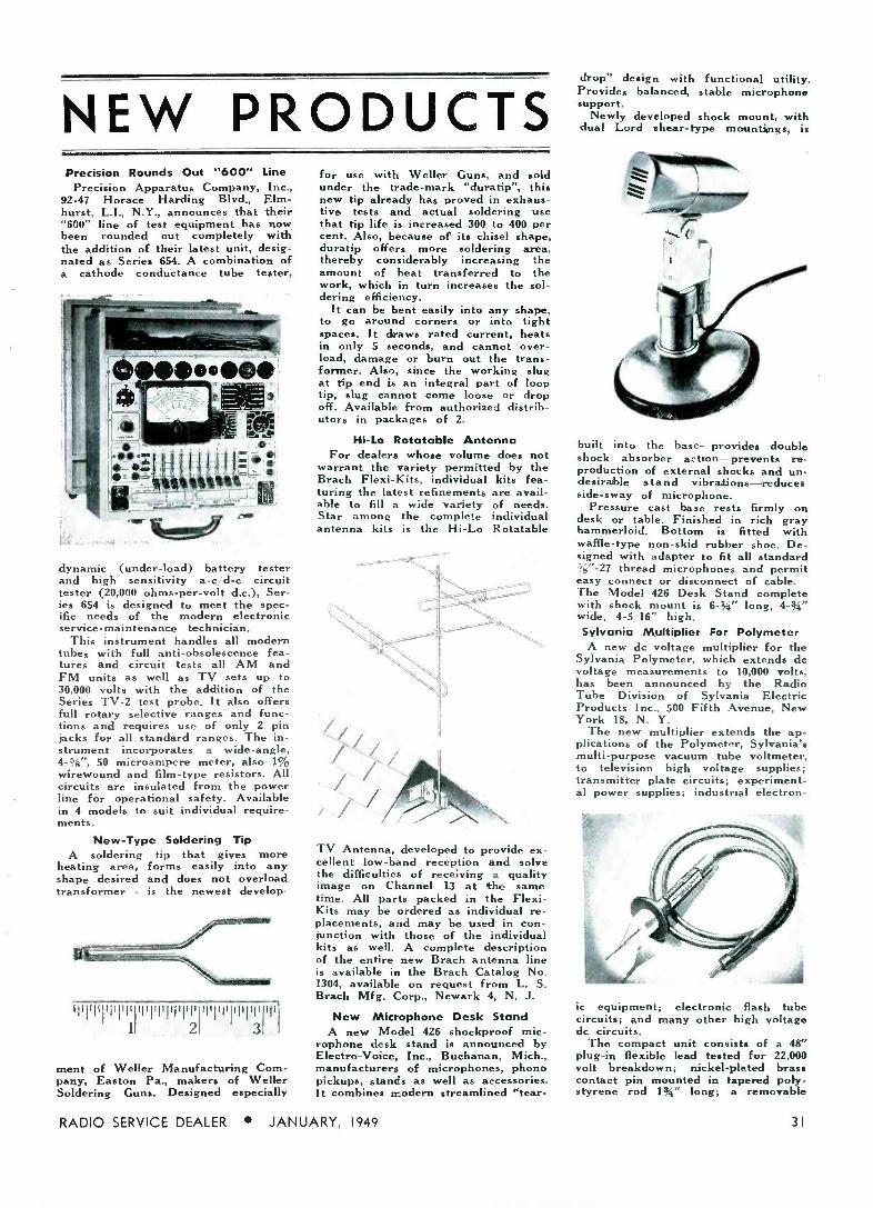
NEW PRODUCTS Precision Rounds Out "600" Line
Precision Apparatus Company, Inc., 92-47 Horace Harding Blvd., Elm- hurst, L.I., N.Y., announces that their "600" line of test equipment has now been rounded out completely with the addition of their latest unit, desig- nated as Series 654. A combination of a cathode conductance tube tester,
dynamic (under -load) battery tester and high sensitivity a -c/d -c circuit tester (20,000 ohms -per -volt d.c.), Ser- ies 654 is designed to meet the spec- ific needs of the modern electronic service -maintenance technician.
This instrument handles all modern tubes with full anti -obsolescence fea- tures and circuit tests all AM and FM units as well as TV sets up to 30,000 volts with the addition of the Series TV -2 test probe. It also offers full rotary selective ranges and func- tions and requires use of only 2 pin jacks for all standard ranges. The in- strument incorporates a wide-angle, 4-ge", 50 microampere meter, also 1% wirewound and film -type resistors. All circuits are insulated from the power line for operational safety. Available in 4 models to suit individual require- ments.
New -Type Soldering Tip A soldering tip that gives more
heating area, forms easily into any shape desired and does not overload transformer - is the newest develop-
ili1il1`1I1111 ilipllvliiip 11 2
ment of Weller Manufacturing Com- pany, Easton Pa., makers of Weller Soldering Guns. Designed especially
for use with Weller Guns, and sold under the trade -mark "duratip", this new tip already has proved in exhaus- tive tests and actual soldering use that tip life is increased 300 to 400 per cent. Also, because of its chisel shape, duratip offers more soldering area, thereby considerably increasing the amount of heat transferred to the work, which in turn increases the sol- dering efficiency.
It can be bent easily into any shape, to go around corners or into tight spaces. It draws rated current, heats in only 5 seconds, and cannot over- load, damage or burn out the trans- former. Also, since the working slug at tip end is an integral part of loop tip, slug cannot come loose or drop off. Available from authorized distrib- utors in packages of 2.
Hi -Lo Rotatable Antenna For dealers whose volume does not
warrant the variety permitted by the Brach Flexi-Kits, individual kits fea- turing the latest refinements are avail- able to fill a wide variety of needs. Star among the complete individual antenna kits is the Hi -Lo Rotatable
TV Antenna, developed to provide ex- cellent low -band reception and solve the difficulties of receiving a quality image on Channel 13 at the same time. All parts packed in the Flexi- Kits may be ordered as individual re- placements, and may be used in con- junction with those of the individual kits as well. A complete description of the entire new Brach antenna line is available in the Brach Catalog No. 1304, available on request from L. S. Brach Mfg. Corp., Newark 4, N. J.
New Microphone Desk Stand A new Model 426 shockproof mic-
rophone desk stand is announced by Electro -Voice, Inc., Buchanan, Mich., manufacturers of microphones, phono pickups, stands as well as accessories. It combines modern streamlined 'tear -
RADIO SERVICE DEALER JANUARY, 1949
drop" design with functional utility. Provides balanced, stable microphone support.
Newly developed shock mount, with dual Lord shear -type mountings, is
built into the base-provides double shock absorber action-prevents re production of external shocks and un- desirable stand vibrations-reduces side -sway of microphone.
Pressure cast base rests firmly on desk or table. Finished in rich gray hammerloid. Bottom is fitted with waffle -type non-skid rubber shoe. De- signed with adapter to fit all standard ;,"-27 thread microphones and permit easy connect or disconnect of cable. The Model 426 Desk Stand complete with shock mount is 6-%" long, 4-94" wide, 4-5 16" high. Sylvania Multiplier For Polymeter A new dc voltage multiplier for the
Sylvania Polymeter, which extends dc voltage measurements to 10,000 volts, has been announced by the Radio Tube Division of Sylvania Electric Products Inc., 500 Fifth Avenue, New York 18, N. Y.
The new multiplier extends the ap- plications of the Polymeter, Sylvania's multi -purpose vacuum tube voltmeter, to television high voltage supplies; transmitter plate circuits; experiment- al power supplies; industrial electron-
ic equipment; electronic flash tube circuits; and many other high voltage dc circuits.
The compact unit consists of a 48" plug-in flexible lead tested for 22,000 volt breakdown; nickel -plated brass contact pin mounted in tapered poly- styrene rod Ix" long; a removable
31

IN every type of service Racon Speakers, Horns and Trumpets 3
operate at higher efficiency than conventional makes through AD- VANCED ENGINEERING. Do not be misled by similarity in
outward appearance. Only Racon, embodying special features of internal construction, can give you the outstand- ing superior performance of a Racon unit.
Racon Double Re -Entrant Trumpet Designed to deliver highly concentrated sound over long distances with highest efficiency. Free from resonant effects. Seven models in bell diameters from 101/4" to 251/2". Also four radial models in widths from 9" to 36".
RE15 - Re -Entrant Trumpet, 18" a- mustie length.
List Price $34.00 (as illustrated).
RASOS - Midget Marine. List price $40.00 (as illustrated).
REPOT - Junior Giant With Alni- co V Magnets.
List price $50.00 (as illustrated).
Racon Double Re -Entrant Marine Speakers. Made from a heavy aluminum spinning with heavy aluminum casting for base. Waterproof; not affected by extreme temperature changes. Four models in bell diameters from 61/4" (Min- iature marine) to 14" (regular marine). Designed for long range reproduction and pick-up in all types of service. Regular, Midget and Miniature Models approved by Bureau of Marine Inspec- tion and Navigation and Dept. of Commerce, for shipboard use.
Permanent Magnet Horn Units These units, highly popular in all types of service, embody many improvements. Two groups, one with Alnico V Magnets and one with Alnico Blue
Dot Magnets. All steel parts plated to prevent corrosion. Also fitted with corrosion proof meta! or plastic diaphragms. Voice coil impedance on
all units: 15 ohms. Special ohmages on request.
Write for Catalog of Complete Line
RACON ELECTRIC CO., INC. 52 E. 19th Street., New York 3, N. Y.
RACON 32
(Speakers Norm Um/Zs-
/lams
bakelite safety flange 2" in diameter; and varnished bakelite handle, 444' long, enclosing dropping r e s i s t or tested at 30,000 volts.
When used in place of the standard Polymeter low -voltage probe, it mul- tiplies each of the present dc voltage ranges by a factor of 10.
New IRC Resistors To meet the increased requirements
of radio service technicians, IRC has announced the addition of 91 new rangea to its current line of Power Wire Wound Resistors. This provides servicemen with a full range of rat- ings, sizes and terminal types.
Special "climate -proof" cement coat- ing provides maximum heat dissipa- tion and humidity protection. These
full-size heavy duty resistors will op- erate continuously at full rating; no derating is required in high ranges.
Supplemelntal catalog sheet listing all ranges in fixed and adjustable types, available terminals, tolerances - and list prices may be had at no - charge by writing International Re- sistance Co., 401 N. Broad St., Phila- delphia 8, Pa.
New G.E. TV Antenna Two new high band adapters and a
one package high -low antenna for television have been announced by the Receiver Division of General Elec-
[Continued on pare 341
$1.00 to $5.00 PAID
for "SHOP NOTES" Write up any kinks or "tricks -of -
the -trade" in radio servicing that you have discovered. We will pay from $1
to $5 for such previously unpublished "SHOP NOTES" found acceptable. Send your data to "Shop Notes Editor," RADIO SERVICE DEALER, 342 Madison Ave., New York 17, N. Y. Unused manu- scripts cannot be returned unless accom- panied by stamped and addressed re- turn envelope.
RADIO SERVICE DEALER JANUARY, 1949

F co
P .o P -
C A 2 Q _ w
,O 2
Reputation is not built overnight! Radiart's reputation has grown over the years because of its many points of superiority! Beyond the fact that the quality and design of every one of the 82 types of Radiart Vibrators ... is beyond compare
. the solid completeness of the line makes them the favorite wherever good vibrators are sold FOR MOST EVERY NEED TO ORIGINAL SPECIFICATIONS ... there is a CORRECT Radiart replacement vibrator! NO OTHER VIBRATOR MANUFACTURER CAN MAKE THAT STATEMENT! Guess work is eliminated .. all good jobbers carry most all numbers in stock ... if your jobber does not have the number you want ... he can get it, FAST ... as special orders are given speedy attention ... with immediate shipment of his order! Insist on Radiart for the EXACT REPLACEMENT Vibrator .. .
IT'S RIGHT WHEN IT'S RADIART
LEADING THE FIELD SINCE 1935
THE RADZART CORPORATION CLEVELAND 2, OHIO
EXPORT... SCHEEL INTERNATIONAL... CHICAGO 18, ILLINOIS
RADIO SERVICE DEALER JANUARY, 1949 33

BACK NUMBERS of "RSD" Order then. now - the supply is low.
JANUARY 1946 Applying Neg. Feedback in Audio Amps. New Philco I -M Circuit RMA Resist. & Conds. Chart FEBRUARY 1946 Applying Neg. Feedback in Audio Amps. Service Market in Industrial Electronics Ballast Tube & Plug-in Resistor Chart
APRIL 1946 Modern Tube Testing, Part I, Methods Servicing Sound Systems Short-cuts on Intermittants by use of
"Substitution Block"
JUNE 1946 Modern Tube Testing, Part 2, Instruments Short-cuts in Trouble -Shooting Ohmmet., Cond-Testers, Cap -Met., Part 2
JULY 1946 Distortion-Determining the Cause, Part I
Ohmmeters, Cond-Testers, Cap. -Met. Part 2
Multivibrators
AUGUST 1946 How Is Your Grid Biased? Part I
Distortion-Determining the Cause, Part 2
Sound Distribution Systems
SEPTEMBER 1946 Transconductance-Reading Tube Tests How Is Your Grid Biased, Part 2
Centralized Radio Servicing
NOVEMBER 1946 The TV Opportunity-Installing & Servicing Don't Miss "Hidden" Profits, Part I
Service Market i dustrial Electronics
DECEMBER 19+6 Modernizing Sets by Using New Rectifiers Deflection Generators in TV
Guide for Miniature Electron Tubes Answers to FM Servicing Problems
FEBRUARY 1947 Simple Methods to Determine Impedances Servicing Record -Changers How To Block Interference MARCH 1947 Antenna Multicouplers Servicing P -A Installations Trade Standards for TV Installations Industrial Maintenance
APRIL 1947 Using Your 'Scope in Radio Servicing Analysis of Coil Checkers "Spars" At Work Trouble -Shooting in P -A Installations
MAY 1947 Oscillator & Power Supply Troubles Ion -Trap in C -R Tubes P -A System Design & Applications, Part I
JUNE 1947 Simplified Set Checking P -A System Design & Applications, Part 2
TV Installing Is A Specialty Business
Servicing 3 -Way Portables
JULY 1947 Frequency Modulation, Part I, antenna
fundamentals & signal shifting effects Automatic Gain Control Circs. in TV Sets Using Conventional Sig. Gen. for FM Align. AUGUST 1947 TV R -F Circuits Described FM, Part 2, receiver circuit fundamentals TV Antenna Installation Problems SEPTEMBER 1947 Substitution Boxes Lick Service Problems TV Antennas for Multi -Unit Dwellings FM, Part 3, Discrim. & Deaccentuation
Nets. OCTOBER 1947 Add Record-players to Modernize Old Sets P -A Fundamentals & Complexities Modern TV Kits NOVEMBER 1947 TV Antennas-Their Characteristics &
Applications Bookkeeping Simplified Make A Universal Test Speaker Eliminating Cathode Heater Hum from
Audio Amplifiers DECEMBER 1947 A New TV Set Servicing Technique Ratio Detection & Its Applications External Cross Modulation-Its Cause &
Cure JANUARY 1948 Master vs Indoor TV Antennas Audio Extractor for Signal Generators TV Kit Alignment Procedures 70 Volt Speaker Distribution Line FEBRUARY 1948 High Speed Servicing Visual Alignment Income Tax Deductions MARCH 1948 Know Your Tube Tester TV Power Supplies A -C/D -C Battery Set Circuits APRIL 1948 Video I -F Circuits & Applications Computing What Price to Charo, Using 'Scopes For Radio Servicing MAY 1948 FM Set Alignment Procedure Video Detectors How Vectors Simplify Servicing Significance of Power Factor and Q JUNE 1948 Amplifier Checking by Signal Injection Applications of Gas Type Tubes Modern TV Kits
JULY 1948 Television's Service Outlook Video Amplifiers Bad Acoustics Cured Electrically AUGUST 1948 FM & TV Boosters Appliance Repair Hints for Radiomen Video Amplifiers D -C Component
rRADIO SERVICE DEALER MAGAZINE 342 MADISON AVE., NEW YORK 17, N.Y.
Please send me the back numbers checked here . .
The price is 35c. for each copy unless 10 or more are ordered. If 10 or more are ordered the price is 25c. each copy.
Jan. 1946 [1 Feb. 1946 [ Apr. 1946 [T June 1946 [ July 1946
Aug. 1946 [ Sept. 1946 7 Nov. 1946
[ Dec. 1946 [7 Feb. 1947 E Mar. 1947 rl Apr. 1947 [T May 1947
June 1947 July 1947 [ Aug. 1947
Sept. 1947 Oct. 1947 Nov. 1947 Dec. 1947 Jan. 1948 Feb. 1948 Mar. 1948 Apr. 1948
I remit herewith $ for the copies ordered at e. each.
NAME
A DDRESS
CITY
[l May 1948 [ June 1948 E July 1948
Aug. 1948
ZONE STATE
34
tric's Electronics Department at Syr- acuse, N. Y.
The one adapter 7UKT-002, de- signed primarily for use with the G -E folded dipole antenna with reflector, may also be used with the folded di- pole without reflector. Where only high band signals are available it may be used as an antenna by itself. The other adapter UKT-003, is designed for high gain operation in conjunction with the G -E stacked array high gain antenna. The high -low antenna con sists of a folded dipole with reflector, packaged with the high band adapter, in one complete unit, including all ac- cessories. As are all G -E TV anten- nas, these adapters are made of hard drawn aluminum, and terminal blocks are of Textolite plastic, formed under pressure.
Further information on the G -E line of TV antennas is available f-om the Parts Section, G -E Receiver Div- ision, Electronics Park, Syracuse, N.Y.
New Transvision TV Units Transvision, I n c., New Rochelle,
N.Y. makes available a number of new TV units to the trade. Among these is the Model No. SG sweep signal generator, shown below for TV and FM alignment.
Features of this new piece of test equipment include: frequency range from 0-227 mc. . . dial calibrated in frequency sweep width from 0-12 mc completely variable . . self-con- tained markers readable directly on the dial to 5% or better (no external generator required to provide the marker signals) . . crystal controlled output makes possible any crystal con- trolled frequency from 5-230 mc high output . . directly calibrated markers, 20-30 mc for trap, sound, and video i -f alignment . . unmodulated r -f signal to provide marker pips simul- taneously with the main variable oscil- lator . . phasing control.
CIRCUIT CO I It 7'
[from
Crosley 65T series Many schemes have been, used in
different a -c/d -c receivers to elimin- ate the i)ower frequency hum which seems to choose such instruments for special attention. Half wave rectifi- ers and lack of filter chokes contrib- ute to the problem. Large filter con -
RADIO SERVICE DEALER JANUARY, 1949

G -E VARIABLE RELUCTANCE CARTRIDGE
cuitd die aeft2aceadEe eúyPue ¿lax
eoweieetteeptal arad 4arag Peaeeet9Zecoedd NOW -in one small unit-all the sales and perform- ance advantages of the G -E Variable Reluctance Cartridge plus this additional consumer economy feature-the Replaceable Stylus.
Negligible needle scratch and needle talk, mini- mum record wear, wide frequency response, free- dom from resonance peaks, realistic reproduction -these are maintained at all times, simply, easily, economically with the Replaceable Stylus.
No more changing of the entire cartridge means more frequent replacement of stylus by the consum- er because he can do it himself so easily.
Four simple steps-and presto! The worn stylus is replaced and maximum high quality performance i3 restored far the critical listener.
Note, too, these additional features: .. .11 New notched design ... one-third smaller .. im- proved shape . . . more generally adaptable to various tone arms.
More clearance for record changers.
Higher lateral compliance for more faithful tracking.
More economical for the customer-more sales for the dealer.
Cartridges availably for LP records with 1 mil stylus; for conventional records with 3 mil stylus.
For complete information on the new Variable Reluctance Cartridge write: General Electric Com- pany, Electronics Park, Syracuse, New York.
11 Simply remove cartridge from 11 tone arm.
3 Insert new stylus into cartridge with fingers.
j Use paper clip or wire to force stylus out of the cartridge.
j Press firmly into position with v thumb nail.
eczzrAz/707n Colt r rcc r r
GENERAL$) ELECTRIC RADIO SERVICE DEALER JANUARY, 1949 35

deniers are the rule in most sets. The Crosley 56T sets utilize an in-
genious method of making the hum lift itself by its boot -straps. The cir- cuit is a conventional 5 tube receiv covering only the AM broadcast ban I.
A partial circuit indicates the por- tions of the schematic in question.
The first audio stage uses the triode portion of the 12SQ7 and the final audio tube is a 50L6. The d -c output of the 35Z5 rectifier is applied direct- ly to the plate of the 50L6, a 60 µf condenser acting as filter. This is followed by a 1200 ohm resistor and a 20 µf final filter. This voltage is applied to the 50L6 screen and all
Model ATR
Size of rotor unit 73/4
x 51/4"x s"
Method of bucking oui hum in Crosley 56T Series receiver, through detector.
other tubes in the set. The plate load of ,the 12SQ7 triode
Se de 6ecim
WITHTENNAROTOR
e 049 LIST PRICE
$ 9S 39 Operates in any weather.
Fits most types of antenna.
CONTROL BOX Size of box 5" x 5" Approx.weight 12lbs.
Alliance Tenne -Rotor is an electric antenna rotator. It assures
correct antenna "beaming"-gives positive control of antenna
rotation to select the exact position for "peaked" reception!
Tenna-Rotor is quick and easy to install-the electric powered
rotor unit resists corrosion-is enclosed in a split zinc, die-cast
housing, and is operated from a plastic control box which plugs
into any 110 volt, 60 -cycle house circuit. A 3 -position switch
rotates antenna clockwise or counter clockwise and stops it at
the right point. Four -conductor inter -connecting cable from rotor
to control box is made available at 51/26 per foot.
TV and FM service dealers, and users, will find that the Alliance
Tenna-Rotor simplifies and improves new and existing installations!
Write for catalog sheet and illustrated folder.
alliance motors ALLIANCE MANUFACTURING COMPANY ALLIANCE, OHIO
Export Department; 401 Broadway, New York, N. Y., U. S. A.
consists of a 470K ohm unit. It is inevitable that some hum will be re-
maining to be applied to the plate, and be subsequently amplified by the output tube. The trick employed is
to couple some of the plate circuit hum into the grid circuit of the tri- ode. This is accomplished by tapping part way up on the grid return, in this case up 22K ohms in series with 5 meg.; the 180 degree phase change in the tube acting to buck out the hum in the plate circuit by cancella- tion. A .02 µf capacitor will be seen providing the feedback voltage.
Motorola 107F series
This ten tube, a -c, FM and AM chassis has, among other interesting features, a novel method of obtain- ing out -of -phase audio to actuate the 6V6 output tubes. A variety of cir- cuits have been developed to achieve this result and it seems that there is no end to the possible variations.
Phase inversion in Motorola 107F.
A portion o f the schematic is shown, illustrating the details of the output Mage. The previous tube in the cir- cuit is a 6SQ7, whose triode section acts as the first audio stage. The output is coupled to the grid of the first 6V6 in the usual R -C manner, the grid circuit being supplied fixed bias through the 470K ohm resistor.
After amplification in the 6V6, the
36 RADIO SERVICE DEALER JANUARY, 1949
-says Bud Ward, Owner of Ward's Radio Service, 24 Town Street, Norwichtown, Connecticut.
Leading Servicemen from Coast -to -Coast
Build Better Business with
Bud Ward is an invalid paralyzed from the neck down. He mastered radio and repairs with his "voice"... by directing the hands of an ex -Marine apprenticed to him under the G-1 Bill. Though handicapped, Bud Ward is known as a radio wizard around Norwichtown and has built up a mighty successful servicing business. "My Rider Manuals are my bible of radio servic- ing,' says Bud. "Having to use someone else's hands to do my work, the clear and concise sevice data is a 'must' with me."
RIDER MANUALS A ready -reference for all sets from 1930 to 1948 - Volumes 1 to 18 are at your Jobber's now. He also has Volume 1 of the Rider Television Manual.
TELEVISION MANUAL PLUS 2 Separate
Books, "HOW IT
WCRKS" and INDEX
If you operate in a TV area, a John Rider
IV Manual is as important to you as a pair
Television Manuals contain DATA
the pliers. FIRider RELIABLE them -
supplied by
the set manufacturers you su PPl Ted have to guess .
You don'twrong and what's selves. what'stely GIANT know i mined°Each Manual includes
Schematics to guide you and your men
to be done. TV servicing SIZE Schema of any
to a quick solution
problem.
'll. flodfeoc mad le RIDER PA MANUAL The first industry -wide public address equipment Manual incorporating the amplifier production of 147 manufac- turers from 1938 to 1948.
2024 Pages PLUS "How It Works" Book which explains theory of various PA circuits and method of rapidly locating faults. $goo
Including index. Q
RIDER MANUALS Television Manual, Voume I,
(plus How It Works and Index) $18.00 Volume XVIII 19.80 Volume XVII 16.50 Volume XVI 8.40 Volume XV 19.80 Volume XIV to VII
(each volume) 16.50 Volume VI 12.50 Abridged Manuals I to V
(one volume) 19.80 Record Changers and
Recorders 9.00 Master Index, Covering,
Manuals, Vols. Ito XV 1.50
18 2036 Pages PLUS Separate "How It Works" Book and Cumulative Volumes XVI, XVII, and XVIII INDEX. Both Books, Complete..,
Rider Manuals $7980 GREATEST Give You and 1T
COVERAGE .. . 27,000 models AM nd FM'
chassis '^ 23.830 poses ..
g
AUTHORIZED FACTORY -FACTS... servi, (accu tech
tques direct from CIRCUIT THEORIES
the set manu- Itfacturersw Works" ORIES EXPLAINED,. mechanic- Books explain electronic I innovations
in sets and Manuals. covered by LOWER COST .. Rider model. dates
r less than a penny
Manua deliver Y per receiver
JOHN F. RIDER, PUBLISHER, Inc. 480 Canal Street, New York 13, N. Y.
Export Agent: Rocke International Corp., 13 E. 40th St., N.Y.C. Cable, ARLAB.
NOTE: The Mallory Radio Service Encyclopedia, 6th edition, makes reference to only one source of radio receiver scnemotics-Rider Manuals.
ANOTHER NOTE: The C -D Capacitor Manual for Radio Servicing, 1948 edition No. 4, makes reference to only one sour,- cf receiver scnematics-Rider Manuals.
RADIO SERVICE DEALER JANUARY, 1949 37

upper one in the print, the signal appears across the upper primary coil of the output transformer. Note that the bottom of this coil does not con- nect directly to the B voltage source, but is isolated from it by a 300 ohm resistor. The audio drop across this resistor is fed through a .01 mfd. capacitor to the grid of the second 6V6 tube. Having been reversed 180 degrees in the first 6V6 it is now in the proper phase to excite the second tube. Bias is again via a 470K ohm resistor from the fixed source.
The only special items needed to incorporate this method of operation
are the transformer with separate primaries for the two tubes, and the 300 ohm resistor. If relacement is needed it would be necessary to ob- serve proper polarity in the two primaries.
INCOME TAX [from page 30]
one or lumped together into a ready- made package. On the short form, the government allows you roughly ten percent of your "adjusted gross income" (which is your business net
ORIENT AMPHENok
adaat smarm to t!e co-iteede:9313 a/zea,...
ORIENT T.YO CHANNELS
IN The DIRECTIONS The usual objective of Antenna Stacking is for the purpose of
acquiring db gain-with Amphenol's 114-302 Stacked Array there is
a plus value, another adaptation, one which is very important in con-
gested TV areas. Both the upper and lower bays provide all -channel
reception and each bay may be individually oriented. Overlapping sig-
nals or station interference on same channels within receiving areas may now be separated-if and when the bays are stacked for orientation. In
the smaller illustration lower right, observe the same array stacked for db gain on all channels. Amphenol Antennas offer many plus values in being perfected electrically and mechanically in every detail.
To keep posted on all that's new in TV and FM Antennas, be sure your name is on the Amphenol list
to receive the monthly issue of EN- GINEERING NEWS. Current issue contains timely information on these subjects-yours for the asking.
AMERICAN PHENOLIC CORPORATION 1830 SO. 54TH AVENUE CHICAGO 50, ILLINOIS
profit) for personal expenses that are legal income tax deductions. On the long form, you roll your own. You list them individually. The govern- ment allows you no blanket deduc- tion. If you think that more than ten percent of your net business in- come (your "adjusted gross income" on the forms) was spent for such de- ductible things as medical attention and state or city gasoline tax on your personal driving, 'then you'll make money by using the long form.
Many radio service dealers and other business men mistakenly be- lieve that it is necessary to use the long form in order to take all of their business expenses as tax de- ductions. This is not so. You can take all of your business overhead items off a short form return as well as a long form return. The long form is used only when you wish to itemize personal a n d family deductions. That's why so many tax accountants and attorneys advise their clients to forget about the long form altogether.
Until the passage of the new Rev- enue Act that lowered income taxes slightly, there was a drawback that prohibited business men who made fairly sizeable incomes from using the convenient short form. Only those whose incomes were below $5000.00 were permitted to take the blanket 10% deduction allowed on the short return. Now, however, the standard deduction has been extended to those making up to $10,000. The law allows $1000 or ten percent of the income.
Joint Returns
However, if you plan to take ad- vantage of the new community property provision in the Act, which extends the privilege to all taxpayers regardless of the laws of the state in which they live, watch out! In a
joint return, or in the return of a
single man, the $1000 -or -ten -percent is allowed, but it is different with married persons sending in separate returns. Each is allowed to take off no more than $600 for the standard blanket deduction.
Extending the community property privilege to citizens of all states, at least as far as income tax is con- cerned, allows the appliance dealer whose net business profit was $10,000 or under to use the short form. Citi- zens of the thirteen community property states have been able to do this all along. Thus, if you made $9980.00, you report $4940 as your net income, and $4940 as your wife's net income-making you eligible for
38 RADIO SERVICE DEALER JANUARY, 1949
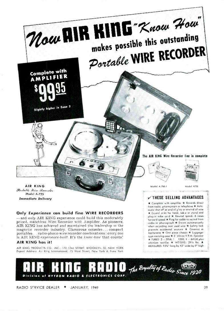
99 *4JB KiUG'«' makes possle this outstanding
yyIRE RECORDER
Slightly higher in Zone 2
AIR S))
KING ¡¡
erMModel
A-725
Immediate Delivery
Only Experience can build fine WIRE RECORDERS -and only AIR KING experience could build this moderately priced, matchless Wire Recorder with Amplifier. As pioneers, AIR KING has achieved and maintained the leadership in the magnetic recorder industry. Glamorous consoles ... compact portables ... radio -phono -wire recorder combinations: every one is AIR KING experience -built. It's the know-how that counts! AIR KING has it! AIR KING PRODUCTS CO., INC., 170 53rd STREET, BROOKLYN 32, NEW YORK Export Address: Air King International, 75 West Street, New York 6, New York
The AIR KING Wire Recorder line is complete
Model A -750-I LJodel 4700
V THESE SELLING ADVANTAGES
* Complete with amplifier * Records direct from radio, phonograph or telephone * Auto- matic shut-off at end of play or rewind of wire * Crystal mike for hand, table or stand and plug-in mike cord * Rewind speed: 6 times
forward speed * Plug for cable to record from radio or phonograph * Erases automatically when recording over used wire * Safety lock
prevents accidental erasure * Covered in
leatherette * One piece chassis * Luggage -
type carrying case * 5" Alnico V P.M. Speaker * TUBES: 2 - 50L6, 1 - 1280, 1 - 6AQ6 plus selenium rectifier * WEIGHS: 211 lbs. * MEASURES: 133/4" long by 12" wide by 9" high
AIR King RADIO Division of HYTRON RADIO d ELECTRONICS CORP.
Pamegoi244e s o
RADIO SERVICE DEALER JANUARY, 1949 39

the short form's convenience and sav- ings and also reducing the size of the tax considerably, since both fig- ures fall into a bracket lower than the $10,000 figure does.
To see how much difference this makes, consider the case of a dealer whose "adjusted gross" income was exactly $9980.00, and who split his income by reporting half of it as his own and half as his wife's. They would pay $2640.00 without splitting. Taking it as a split income, they would each pay $687, a total of $1374. The saving: $1266!
The most important thing to any business man is an exact knowledge of what he may deduct as business expense, and what he may not.
Roughly speaking, anything you pay out in order to run your business is a business expense.
Here is what the Treasury De- partment has to say about business expenses: `Business expenses may include reasonable salaries and wages paid, interest on business indebted- ness, taxes on business and business property, loss arising from business operation, bad debts arising from
12 WAYS TO CUT CONTROL INVENTORIES
IRC Tap -In cut to desired lengths before being installed. In crowded chassis, they can be installed after control is assembled- eliminating any necessity to remove other parts. There's an IRC Tap -In Shaft for most radio and television requirements. Used with IRC Tap -In Shaft Controls, you are sure of smooth, quiet, trouble - free service. Ask your distributor forlRC Controls-with the dependable Tap -In Shaft feature. International Resistance Company, 401 N. Broad Street, Phila- delphia 8, Pa. In Canada: International Resistance Co., Ltd., Toronto, Licensee.
You can reduce your stock of re- placement controls, and profit in time and money with these 12 IRC Tap -In Shafts. IRC engineered for easy instal- lation and dependable performance with IRC Tap -In Shaft Controls, they cut both service time and costly stocks of exact duplicates.
Accurately tapered sockets in IRC Tap -In Shaft Controls readily receive the closely machined shaft ends. A firm hammer t rmanently "freezes" the two units. '`washers and other cum- bersome to king arrangements are entirely eliminated. IRC Tap -In Shafts are quick, eÌ sy .. and secure!
fts can be conveniently
INTERNATIONAL RESISTANCE CO.
Cvtaut Scua-^nr
SHAFT A standard, double flatted
SHAFT B
slotted or tongued
SHAFT E
universal split, knurled
SHAFT F
ït' dia., full round
SHAFT G
special slotted
SHAFT H
slotted with groove
SHAFT J
%" dia. with .105" flat
SHAFT K
special /4" round
SHAFT l flatted with groove and
threaded hole
SHAFT M
double flatted, threaded
Çcn d slotslotted
SHAFT %" full round
sales or services (provided the income portion of the amount due has prev- iously been reported in income), depreciation, obsolescence, depletion and rents, repairs and other expenses."
The Treasury also points out that :
"Other items are management ex- penses, commissions, labor, supplies, advertising or other selling expenses, and insurance premiums paid."
Also included are the upkeep and depreciation on cars and trucks used in the business' membership in trade associations, other clubs and Cham- bers of Commerce where it is some- times good business to belong, sub- scriptions to publications (like this one) that you use to help you conduct your business, the cost of supplies, postage, etc., equipment that has only a short life, depreciation on equip- ment and fixtures that has a life longer than one year, any entertain- ment that actually helps the business and, finally, travel and transportation expenses.
There is one item of business ex- penses you'll find tricky. Many deal- ers have written off the cost of materials they purchased-and later found themselves coughing up back tax payments plus, on occasion, in- terest as well. This is because any- thing you have in your inventory is not a business expense. You still have it. Until it leaves your physical pos- session through sale, or until it is definitely written off useless, it's an asset, not an expense.
When you take a deduction for bad debts, the Treasury insists that your return show: "(a) the nature of the debt; (b) name and family relation- ship if any of the debtor; (c) when the debt was created; (d) when it became due; (e) what efforts have been made to collect the debt; and (f) how it was determined to be worthless."
Uncle Sam wants all of this in- formation because of the opportuni- ties for fraudulent deductions that dishonest taxpayers have when they claim bad debt losses. Bills rendered that have remained unpaid are not necessarily bad debts in an income tax sense. A deduction for a bad debt loss is allowed only if you have previously reported the sum due you as income. In other words, the debt must have been reported as income at some time or you can't take it off as a loss.
Depreciation
How do you figure depreciation ?
Supplies and other incidental pur- chases that have a short life only -
40 RADIO SERVICE DEALER JANUARY, 1949

ALL THE FUN 2/3 T-1 E COST
i fre4g. VACUUM TUBE
VOLTMETER KIT Everything you want in a VTVM. Shat- terproof solid plastic meter face, auto- matic meter protectiorrin bu:n-out proof circuit, push pull electronic voltmeter circuit assuring maximum stability. Linear DC and AC scales. AC and DC full scale ranges of 3V -10V -30V -100V - 300V -1000V. A total of 24 ranges. Isolated DC test prod for signal tracing and meas-arements of voltage while in- strumentA h 1 is in operation. n o mmeter section accurate y measuring resistance of 1/i0 ohm to one billion ohms with internal battery. Extremely high input resistance 11 megohms on all ranges DC and 6.5 megohms on AC. All these features and many more are the reasons hundreds of radio and television schools are using Heathkit VTVM's and recommending them to all students. Like all Heathkits, the VTVM kit is complete, 110V. 60 cycle power trans- former, 200 microamp meter, tubes, grey crackle cabinet, panel, test leads, 1%r ceramic precision divider resistors and all other tarts. Complete instruction manual. Better start your laboratory now. 24.50 Shipping weight 8 lbs. L J
2 'Weaticket SINE AND SQUARE WAVE
AUDIO GENERATOR KIT The ideal instrument for checking audio amplifiers, television response, distortion, etc. Supplies excellent sine wave 20 cycles to 20,000 cycles and in addition supplies square wave over same range. Extremely low distortion, less than 19j , large calibrated dial, beau- tiful 2 color panel, 1% precision calibrating resistors, 110V. 60 cycle power transformer, 5 tubes, detailed blueprints and instructions. R.C. type circuit with excellent stability. $4.50 Shipping weight 15 lbs.
Heathkits are beautiful factory engineered test equipment kits supplied complete but unassembled with all parts - tubes, grey aluminum cabinets, punched, formed and plated chassis, calibrated panels, ready wound coils and complete detailed instruction manuals for assembly and use. With costs zooming up, Heathkits save the labor cost of as- sembly enabling thousands to have equipment which they otherwise could not afford.
5 74e NEW 1949 HEATHKIT 5 -INCH
OSCILLOSCOPE KIT New Improved model of the famous Heathkit Oscilloscope. Building an oscilloscope is the finest training for television and newer servicing technique and you save two-thirds the cost. All the features and quality of instruments selling for $100.00 or more. Supplied complete with cabinet, two color panel, 5BP1 tube, 2 5Y3 tubes, 2 6SJ7 tubes and 884 generator tube. Power transformer supplies 1000 volt negative and 350 volt positive. Sweep generator 15 cycles to 30 M. cycles. Has vertical and hori- zontal amplifiers. Oil filled filter condensers for long life. Complete blueprints and instructions included. Shipping weight 25 pounds. Express only 39.50
3 s eatigkit CONDENSER CHECKER KIT
Checks all types of condensers, paper mica - electrolytic - ceramic over a range of .00001 MFD. to 1000 MFD. All on readable scales that are read direct from the panel. NO CHARTS OR MULTIPLIERS NECESSARY. A condenser checker anyone can read without a college education. A leakage test and polarizing voltage of 20 to 500 volts provided. Measures power factor of electrolytics between 0% and 50%. 110V. 60 cyde transformer operated com- plete with rectifier end magic eye tubes, cabinet, calibrated panel, test leads and all other parts. Clear detailed instructions for assembly and use. Why guess at the quality and capacity of a con- denser when you can know for less than a twenty dollar bill. 9.50 Shipping weight 7 lbs
4 WWeatlskCt SIGNAL TRACER KIT
Reduces service time and greatly in- creases pi -Au of any service shop. Uses crystal diode to follow signal from antenna to speaker. Locates faults immediate.y. Internal amplifier avail- able for speaker testing and internal speaker available for amplifier testing. Connection for VTVM on panel al- lows visua. tracing and gain measure- ments. Alsu tests phonograph pickups, microphones, PA systems, etc. Fre- quency range to 200 Mc. Complete ready to assemble. 110V. 60 cycle transforme- operated. Supplied with 3
tubes, dioce probe, 2 color panel, all other parts Easy to assemble, detailed blueprints and instructions. Small portable 9"x6"x43/4". Shipping Wt. 10 lbs 1 9.50
RADIO SERVICE DEALER JANUARY, 1949
6 'Wear/ We FM AND TELEVISION
SWEEP GENERATOR KIT A necessity for television and FM. This Heathkit completely covers the entire FM and TV bands 2 megacycles of 230 megacycles. The unit is 110V. 60 cycle transformer operated. Uses two 6J6 tubes, two 6C4 tubes and a 6X5 rectifer. An electronic sweep circuit is incorporated al owing a range of 0 to 10 MC. A sawtooth hor zontal sweeping voltage and phase control are provided for the oscilloscope.
The coils are ready assembled and precision adjdsted to exact frequency. As in all Heathkits, the best of parts are supplied, Mallory filter condenser, zero coef. ceramic condensers, all punched and formed parts, grey cackle cabinet, 5 tubes, test leads, etc. Better get it bui.t now and be ready for the FM and $24.50 TV business. Shipping Wt. 6 lbs. .
7 % edd e SIGNAL GENERATOR KIT Every shop needs a good signal generator. The Heathkit fulfills every servicing need, funiamentals from 150 Kc. to 30 megacycles with st-ong har- monics over 100 megacycles covering the new tele- vision and FM bands. 110V. 60 cycle transformer operated power supply.
400 cycle audio available for 30% modulation cr audio testing. Uses 6SN7 as RF oscil.ator and audio amplifier. Complete kit has every part neces- sary and detailed blueprints and instructions enable tae builder to assemble it in a few hours. Large easy to read calibration. Convenient size S19.50 9" x 6" x 43/4". Ship. Wt.71bs
ORDER DIRECT FROM THIS AD. WE WILL SHIP C.O.D. Add Postage for Weight Shown
HEATH COMPANY BENTON HARBOR 1 2,
MICHIGAN
41

usually less than one year-can be taken off as direct expenses, but equipment, fixtures, machinery and such-things that last a long time- cannot be claimed in whole during the year they are purchased. You must depreciate them. The deprecia- tion time should be roughly the nor- mal life of the item.
Thus, for example, a desk that cost $100.00 could be expected to last ten years. At the end of that time, it would have a resale value of perhaps $10.00. So you would de- preciate the desk nine dollars each year for the decade.
If you use a car for both business and pleasure, figure the part of its life that is devoted to business uses. Then take that percentage of its value. Depreciate the figure you have in the same way that the desk above was figured.
The Collector of Internal Revenue won't raise cain about how you carry depreciation on the books, provided you use any recognized accounting method, figure on a reasonable life, and use the same depreciation pro- cedure consistently. Interest
In writing down the interest you pay on a business debt, be sure that
you do not put down interest on any personal loans you might have made. Your business loan is an expense you incur in making money, but your personal loan is not. You can take off personal loan interest. brt if you use the long form in filing your return. Business loon i,r-e,'- comes off in computing the "adjusted gross" income figure.
Taxes You can take off taxes you have to
pay for doing business but, again, you may not take off taxes on your home or on the cigarettes you smoke -unless you use the long form and deduct them from the "adjusted gross." Like the interest on a busi- ness loan, the taxes on your business (and only on your business) are de- ducted from gross income to arrive at the "adjusted gross" figure, which is no more than the net profit shown on your year-end profit and loss statement.
Other Expenses Where do these various business
expense items go in the conglomera- tion of spaces, boxes and blanks on the long or short income tax form? The easiest way to handle them is to list them just as you would in a
AMPERITE
Ideal for BROADCASTING RECORDING PUBLIC ADDRESS
"The ultimate in microphone quality," says Evan Rushing, sound engineer of the Hotel New Yorker.
Shout right into the new Amperite Microphone-or stand 2 feet away- reproduction is always perfect.
The only type microphone that is not affected by any climatic conditions.
Guaranteed to withstand more "knock- ing around" than any other type mike.
Special Write for Special Introductory Offer, .x1 Offer: and 4 -page illustrated folder.
In Canada: Atlas Radio Corp., Ltd., 560 King St. W.,
42
Models RBLG-200 ohms RBHG-Hi-imp.
List $42.00
"Kontak" Mikes Model SKH, list $12.00 Model KKH, list $18.00
Toronto
regular profit and loss statemen, then write this remark across the various "schedules" provided on the form: "See attached schedule listing ex - "See attached schedule ]Listing ex- penses and deductions."
Be sure that the special profit and loss statement is firmly attached to your tax report. Don't just clip it on. Staple or glue it to the top of the return so it can't get lost in the shuffle of thousands of forms that pour into every Collector's office during January, February and March.
What about other money you might have taken in, such as from the sale of a house, or the dividends paid on corporation stocks, or the profit on a sale of stocks you owned? These three all come under the heading of capital gains (or losses). They should be separately reported on the form that conies with each income tax return. You pay a different tax rate on capital gains.
Briefly, "capital gains" applies to any money you made from the sale, liquidation, etc. of some long-term investment. The purchase of a home is a long term investment. If, during the year, you sold your home for $1000 more than you paid for it five years ago, you have made a capitalgain of $1000. This is not included in the regular listing of business profits and expenses.
In next. month's issue, we'll look at the matter of deductions that govern your decision on using the long forni or the short. form. We'll cite examples of good income tax fiiguring.
PH/l\O PICK UP [front page 25]
The Titone cartridge can be used di- rectly as replacement for a crystal cartridge. It will operate satisfactorily into a half to a ten megohm load. For average use a one megohm load is recommended. Where more bass is desired a higher resistance load is required.
To install: First remove the two screws holding the cartridge to be replaced in place. Detach the termin- als from the old cartridge. If con- nections were soldered solder the wires to the clips of the ceramic pickup cartridge provided in the in- stallation kit. A word of caution: Do not solder wires while clips are attached to the new cartridge. This is a very important point and should always be observed. Plug clips onto the terminal adapter with the ground lead on left hand pin, (looking from
RADIO SERVICE DEALER JANUARY, 1949

for greater
distance d ter
ideo you tan seI
i ,; ll , / fb /
wodtbe lie l, , than the famous VEE-D-X
long range antenna plus
THE NEW VEE-D-X
SECTIONAL TOWER
VEE-D-X maintains its policy of o single source for complete TV antenna installation with its
new sectional tower that can be s.sed ai any height from 10' to '40'. This tower embodies eeery desirable feature that you and your customers could von rst -
Surprisingly law in cost
Rugged. yet light in weight All welded construction in 10' crud- 20' sections Comes completely. assembled Quick, easy erection Diagonally reinforced for highest possible rigidity
C Has universal antenna mount Antenna rotated from base Aluminum finish-requires no painting Extra safe for climbing
euture and install this VEE-D-X "infertile combination and your
u:comers will see the differ- n-<,. fo- literature and dealer or ces, write-
LaPOINTE-PLASCOMOLD CORP. UNIONVItLE, CONN.
MEANS VIDEO DISTANCE
the front of the cartridge when it is in playing position). Another pre- caution: On ac -de sets it is necessary to unground the cartridge. This can be easily accomplished by pushing back the rubber sleeve slightly, then cutting the ground strap (see Fig. 5).
TERMINAL CLIPS
TERMINAL ADAPTER
GROUNDING STRAP
417) RUBBER SLEEVE
MOUNTING SCREWS
NEEDLE GUARD
Fig. 5-Constructional details.
All free parts of metal resulting from this cuting operation should be re- moved from all parts of the pickup.
Mount the new cartridge into the arm using the size of screws match- ing the threads of the old mounting holes. The best use of the pickup and the least record wear is obtained with a needle force at the point of
of an ounce. This may seem min- ute but the pressure carried by the actual point is sometimes in excess of several tons to the square inch. If needle point force is too great, try to adjust the counterweight or the counterbalance spring at the rear of the pickup arm. Remove needle guard and pickup is ready for operation.
If upon completion of the in- stallation the volume output is in- sufficient it may be due to the use of an equalizer network in the input circuit which is not necessary with this new pickup material. If that is the ease, remove the equalizer net- work and make the connection di- rectly.
The pickup cartridge has not had any publicity up to the present time until it was found to give satisfac- tion in practical field and user tests. These tests indicate excellent results on both expensive and low priced phonographs and record players. The pickups have been produced on a
commercial basis since _Mardi, 1947, and several hunderd thousand pickup cartridges have already been de- livered to a number of phonograph manufacturers. They are now or will he shortly available to the public as replacements on pickups now being used on phonographs in literally millions of homes throughout the world. This point is of utmost im- portance to the serviceman.
LA >4tCHT8.Csl ATfRRIj! . iYl-iYç -y!!rtigl:.. t'i
Want Greater Turnover, Higher Returns,
and More Profit? Then here's how to use valuable counter space. Set aside one square foot for this bright, quick -sale Burgess display assortment and watch sales and profit soar.
Here's a whole profit department in one compact, sturdy unit. In less than a square foot of space (actually 9" x 13") it displays and sells 48 Burgess flashlight batteries and a complete assortment of Burgess flashlights in 5 best-selling models. This new money -making display is FREE with the minimum stock of batteries and select flashlight cases.
Don't wait to step up profits. Your Burgess distributor has the No. 134 assortment in stock now. Order it by number today !
BURGESS BATTERY COMPANY Freeport, Illinois
RADIO SERVICE DEALER JANUARY, 1949 43

ONLY
15 75 LIST
STANDARD JOBBER DISCOUNTS
Make sure the antenna yon buy is made of the hardened. durai aluminum tubing, for long- lasting durabii ty and weather resistance
NOT the soft, inexpensive tubing. ALL HY-LITE antennas are built of th- same fin-. strew:. cons:+--,t'nn and hardened dral aluminum that his made HY-LITE the ch -ice of thousand>.
HY- L ITEaiemffle INC.
Makers of Fine Antennos for AMATEUR FM TELEVISION 528 TIFFANY ST., BRONX 59, N.Y.
RUGGED! DURABLE! A POWER SUPPLY
THAT CAN REALLY "TAKE /T
MODEL "A" 6V 15 Amp. or 12V 71/2
Amp. DC filtered from 105V to 125V 60 cycle
power line.
This model has proper rectifier, choke coil, condenser and transformer to provide heavy instantaneous output and still maintain rated output under unusual load and heat conditions.
Ideal long life power supply for testing auto radios with solenoid tuning and tone controls; 12 volt marine and aircraft radios; telephone circuits,
laboratory apparatus, etc.
Write for complete information
ELECTRO PRODUCTS LABORATORIES Pioneer Manufacturers of Battery Eliminators
549 W. RANDOLPH ST. CHICAGO 6, ILL.
el.111. presents annel
e -all v AiTENN
t Ó, COST T _
NO TOOLS REQUIRED
EASILY
ASSEMBLED
FULLY
ADJUSTABLE
IF YOUR JOBBER CAN'T SUPPLY YOU, SEND US HIS NAME. WRITE FOR NEW FREE CATALOG
DI -9
In view of its evident superior characteristics, to wit: light weight and high fidelity, this pickup offer, an excellent medium of introducing new sales opportunities for Radio Service Dealers. One does not have to stretch his imagination to any great extent to realize the additional income producing potentialities of an item of this nature.
A most logical procedure is to con- tact known owners of phono units by postcard, circular, or phone, and to acquaint them with the merits of the new pickup. It is certain that a large percentage of responses will be ob- tained as a result of this procedure. In fact, many of these responses will be due to unsatisfactory operation of the existing equipment due to service requirements.
It then becomes merely routine for the Service Dealer to put the equip- ment in first class condition first, following which the "Titone" unit is installed. No doubt, mechanical diffi- culties will arize-but so far none has been insurmountable. The end result will be a customer who is satisfied for two reasons: first, because of the better condition of his unit, and second, be- cause of excellent pickup used.
TUNED FILTERS
[from page 23]
chosen so as to allow relatively low resistance values for Ri and R2. This is desirable, since the total d -c load current must flow through these two resistors in series, and a high total resistance value would introduce an undersirable voltage drop. Since CI, C2, and Ca are electrolytic capacitors, they must be connected in the polarity shown in Fig. 5. The capacitors and resistors must be selected as closely as possible to have the values given in Fig. 5. However, slight differences in both capacitance and resistance are compensated by adjustment of rheo- stat R1. In order to obtain the resist- ance values given for R2 and R3. these units may be wirewound resistors with their sliders set to the indicated values by means of an ohmmeter. Rheostat Ri may be provided with a slotted shaft for screwdriver adjust- ment, and may be set closely for very effective elimination of hum. Installation of the Tuned Section
The tuned sections shown in Figs. 2 to 5 will remove the 60 -cycle half - wave ripple from the power supply output voltage (or will attenuate it
44 RADIO SERVICE DEALER JANUARY, 1949

w an unnoticeable level) in the most troublesome of cases. They do not affect the hum harmonics, however, and for this reason the tuned section must be followed by a simple untuned section (See Fig. 1). The untuned section may be made up with any available choke which will carry the full d -c output (load) current, and any available high -capacitance filter capacitor. A common combination, for example, is 20 henries and 10 microfarads. The values are not at all critical in the untuned section which is a brute -force circuit.
The parallel -T section (Fig. 5) is not susceptible to magnetic fields, nor does it radiate any, and so may be placed without too much concern in any convenient part of the power
supply section of the chassis. When the tuned section includes a choke, such as those given in Figs. 2, 3, and 4, care must be taken to mount the tuned choke so that its core is at right angles to the choke in the un - tuned filter section. Care also must be taken to keep the tuned choke well away from audio transformers in the supplied circuit.
We believe that the comparative simplicity and other advantages of tuned filter sections will recommend them readily to the builders of equip- ment using transformerless power supplies of the half -wave type. We believe they are equally useful to the radio serviceman who should consider the installation of a tuned section to correct stubborn hum troubles.
FFFIIIItAI,h [from page 21]
compensates for load changes across the amplifier output. Under ordinary operating conditions, these load changes vary continuously and great- ly through a wide dynamic range.
In the first case above, when the content of negative feedback exactly equals the content of positive feed- back, we have an ideal condition. An original pure undistorted signal, somewhat amplified, may be taken from the amplifier. In this we have a stabilized condition sometimes called a balanced condition.
In the second case above, a similar distortion to that known to exist in the original, but of lesser magnitude and opposite in phase, is fed back into the input circuit with the im- mediate result that the original dis- tortion is reduced through opposition. Thus, waveform or harmonic dis -
sic We,
t A CHALLENGE - Order a model 247. Disrenard the unbelievably low price and compare it 1 on the tasis of appearance. guc-.lily and ptnorn.ance to any other Tube p
Tester (AMY MAI< E. ANY PRICE). If you are not completely satisfied with the model 247 after a IS day trial, i return it to us for full refund-no explanation necessary. The model 247 is net surplus nor is it a hashed over pre-war model. It is newly designed and incorporates new
II advances in Tube. Tester design. Read the description- Wow. and. order one today! a. of THE NEW MODEL 247 TUBE
TESTER Checks omits, halals, bantam jr. peanuts, television miniatures, magic eye, hearing aids, thyratrons, the new type H.F. minia-
tures, etc. Features: * A newly designed element selector
switch reduces the possibility of obso- lescence to an absolute minimum. When checking Diode, Triode and Pentode sections of multi -purpose
tubes, sections can he tested individually. A special isolating circuit allows each section to be tested as if it were in a separate envelope. The Model 247 provides a super sensitive method of checking for shorts and leakages up to 5 Megohms between any and all of the terminals. One of the most important improvements, we believe, is the fact that the 4 position fast -action snap switches are all numbered in exact accordance with the standard R.M.A. numbering system. Thus, if the element terminating in pin No. 7 of a tube is under test, button No. 7 is used for that test.
Model 247 comes complete with new speed-read chart. Comes housed in handsome, hand -rubbed oak cabinet sloped for bench use. A slip-on port- able hinged cover is included for outside use. Size: 10%" z 8%" x 5%".
20;6 Deposit Required on All C.O.D. Orders
ONLY
90
NET
MOSS ELECTRONIC DISTRIBUTING CO. 11".P VER -YORK FULNT. O ST.
renounci ng "TELEVISION INTERFERENCE-
Its Causes and Cures" A new Handbook by Radio Magazines, Inc., covering in detail the
important facts of TVI. The TVI Handbook is edited to fill the pressing requirements of amateurs and other technicians confronted with the problems of TV interference, or otherwise unsatisfactory television reception. Included in its thorough treatment of causes and cures
are a comprehensive set of TV screen photos depicting all types of reception, many case histories, preventative design data, and other equally pertinent facts. It is a vital publication for radiomen wherever TV is on, or about to go on the air.
Price 50c postpaid, or order from your local jobber.
CQ-Radio Magazines, Inc. 342 MADISON AVE., New York 17, N. Y.
Enclosed find $ for copies of the TVI Handbook
Name
Address
City Zone State
RADIO SERVICE DEALER JANUARY, 1949 45

46
SERVICEMEN
DEALERS
BUILD YOUR RADIO SALES
AROUND THIS 2u.itry CHASSIS
NEW MODEL 511
ESPEY CUSTOM BUILT
RADIO
This profitable chassis replacemen1. maï ket means increased sales to you and increased savings to over 19
1;{lion potential customers.
Here is a fine radio, in chassis form, fo ploase the most discriminating music lovers.
Easy to install in any console cabinet old or new, the Espey 511 AM -FM radio chassis embodies the latest engineering refinements for lasting high quality at a price that defies competition.
Features, 12 tubes plus rectifier and tuning indicator; drift compensated circuit for high frequency stability; tuned RF on AM and FM, high fidelity push-pull audio; 13 watts power output; wide range 12" PM speaker; smooth flywheel tuning; phono inp_., provision; separate AM and FM antennas.
Sold through your favorite parts distributor. Write for catalogue Dl containing complete specifications.
Makers of fine radios since 1928.
MANUFACTURING COMPANY INC. 528 EAST 72nd STREET, NEW YORK 21, N.,. Y. TEL. BUtterfield 8-2300
5ee4tROuPiG
VOLT-OHM-CAPACITY MILLIAMMETER
4aele ,La oectee rry Sc e Measures resistance 1.1 ohm to 10,000 meg- ohmsl, capacitance, inductance, current, voltage, both AC and DC.
Mail this ad for literature and a free copy of our regular 50c Service Instruction Manual.
THE HICKOK ELECTRICAL INSTRUMENT CO.
10933 Dupont Avenue Cleveland 8, Ohio
RMS VIDEO- ANTENNA
Model SP -2 13 Channel
for your
C USTO M ER SATISFACTORY ' INSTALLATIONS
LESS SERVICE CALLS AUXILIARY SALES
Yes, this PROVEN successful Television Booster will build up profits for YOU- not only because of rapid turnover-but
also because it opens up whole new markets for the sale of television sets, components and accessories, in "fringe areas" where satisfactory television reception was for- merly impossible!
See your local jobber for this, as well as other RMS Television Fast -sellers. Write for literature to
RADIO MERCHANDISE SALES, INC. 548-550 WESTCHESTER AVENUE NEW YORK 55, N. Y.
RADIO
Ionion, arizing within an amplifier, is itself degenerated and tb'refore reduced. Expanded ranges cf fre- quency spectrum can be amplified practically with equality throughout the frequency range.
In the third case above, negative feedback stabilizes the output volt- age or the dynamics of the amplifier under load and as stated these loads vary greatly and continuously. The usual tendency without feedback would be for the output voltage to drop off as the load current or drain increased. What actually happens when negative feedback is applied is the following:
An increased load of course draws a greater current in an amplifier's output circuit. This naturally de- creases the output voltage. But, that action must also decrease the feedback voltage since it is derive l from and paralleled across that same reduced output voltage. Thus the smaller con- tent of feedback introduces less op- position to the original input signal. Then, when that signal has less op- position, the input is effectively larger and being again amplified results in an increased output. From this process output voltages are maintained at steadier mean values. The final pro- duct is stabilization with a minimum of distortion.
Now of course the above benefits are only gained at the expense of a
loss in voltage gain since the very nature of the whole negative feed- back process reduces the possible out- put signal from the amplifier. Yet the gains to be derived from stabilization and freedom from distortion more than offset this loss. It is merely necessary to design the simplifier for a greater amount of gain when nega- tive feedback is employed. High mu tubes producing a greater gain per tube have aided devclopeulent.
To clarify the above an example is detailed. With reference to Fig. 5, suppose sin amplifier without feed- back requires 1 volt input to produce an output of 100 volts. Next assume the introduction of si circuit feeding hack 9 volts inversely to the input when the output is 101) volts. Ten volts will now be required at the input to maintain the original 1 volt across CD (10-9 negative feedback = 1 across CD). The original gain of the ampli- fier was 100/10 = 10. While the gain with feedback added has been reduced. The output over the input or 100/10 = 10. We then may say that the gain of the amplifier with feedback is, Gain = A/1 -FA where A is amplifica- tion without feedback and F is the fraction of output voltage that is fed
(Continued on page 48]
SERVICE DEALER JANUARY, 1949
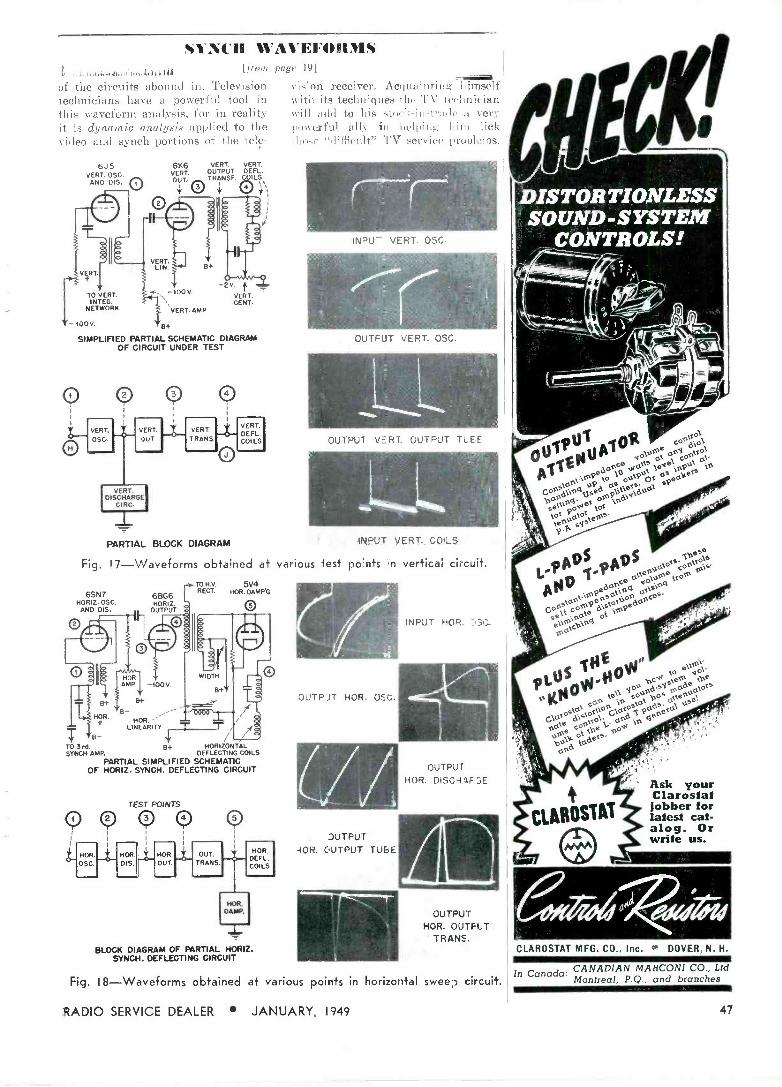
SYNCH WAVEFORMS P..,.,4 In11i..4i1J,;] ,..6í71J1
Mont
of the circuits abound in. Television technicians have a powerful tool in this waveform analysis, for in reality it is dynamic analysis applied to the video and synch portions of the tele -
V
6J5 VERT.
AND DIS.
TO VERT. INTEG.
NETWORK
VERT. LIN.
6K6 VERT. VERT. VERT. OUTPUT DEFL. OUT. TRANSF. OILS rV O + s\
B+
-100 V.
VERT. AMP
-2V. t y VERT. CENT.
-100V. B+
SIMPLIFIED PARTIAL SCHEMATIC DIAGRAM OF CIRCUIT UNDER TEST
VERT.
OSO.
VERT
OUT
VERT. DISCHARGE
CIRC.
VERT TRANS
VERT. DEFL. COILS
page 191
vision receiver. Acquaintinu himself with its techniques the TV technician will add to his stiwk-in-t'.'tlde. aL very powerful ally in helping hint lick ¡hose "difficult" TV service prabkmis.
INDU- VERT. OSC.
OUTPUT VERT. OSC.
OUTPUT VERT. OUTPUT TLEE
PARTIAL BLOCK DIAGRAM INPUT VERT. COILS
Fig. I7-Waveforms obtained at various lest ponts in vertical circuit.
65N7 HORIZ. OSC AND DIS.
B+
HOR. f T B- TO3rd. B+ HORIZONTAL SYNCH AMP. DEFLECTING COILS
PARTIAL SIMPLIFIED SCHEMATIC OF HORIZ. SYNCH. DEFLECTING CIRCUIT
6866 HORIZ.
OUTPUT
TO N.V. 5V4 REGT. HOR. DAMP'S
8+
HOR. ' LINEARITY
TEST POINTS
Y Y Y
BLOCK DIAGRAM OF PARTIAL HORIZ. SYNCH. DEFLECTING CIRCUIT
OUTPJT HOR. OçG..
(// DUTPUT
-10R. GUTPUT TUBE
Fig. 18-Waveforms obtained at various points in
RADIO SERVICE DEALER JANUARY, 1949
INPUT NCR. 'SC.
OUTPUT HOR. DISCHAF 3E
OUTPUT NOR. OUTFIT
TRANE.
horizontal swee D
ooà c 66
vo1me °rY pVto
tiee9ed°o0 .voi \ev io4éty°in
oy a4e6X
b°t' $e"',0 -ele
t
sY vis
S !S "eaa TpA ce
P" vYgt4 ot,s° óto4 ás rocs,daoes i. ema\ch'r4 .-t
lot p ,
e»m -
L 0 M
go to v he
p U / yo úpd-sg tº°rvaOts Kr1 e o
1+ t o o s,P, s° e
G°tosasotoy Good p4e°et°`
r°V é Corhe yro`H lt` adets.
°t'd
Ask your Clarostat jobber for latest cat- alog. Or write us.
CLAROSTAT MFG. CO.. Inc. °'' DOVER. N. H.
In Canada: CANADIAN MARCONI CO., Ltd
circuit. Montreal, P.Q., and branches
47

PUZZLE: What's the
'DCOT DIIV l eel - in MAGNETIC TAPE
RECORDERS? ANSWER: One that gives you twice as
much playing time as outmoded models, at half the tape cost! Write today for technical literature.
AMPLIFIER CORP. OF AMERICA 398-3 Broadway, New York 13, N. Y.
Easier Antenna
Installations
STAR TAMPIN
STAR DRYVIN
.v
STAR STAZIN
STAR SPRINGIN
VisitOurDisplayBooth,I.R.E, Show March 7-4910'
,*STAR EXPANSION BOLT CO. INC.
147 Cedar Street, New York 6, N. Y.
Star Expansion Bolts make it
easy to fasten TV equipment
to brick, stone, concrete or
any other type of masonry.
Help you to position antenna
masts, cables and lines in the
best possible manner...assure
greater satisfaction; reduce
service calls. There's a Star
fastening for every masonry
job. See your jobber or write
for details.
See Your Jobber
Air King Prods. Co., Inc. 39
Alliance Mfg. Co 36
American Phenolic Corp. __38
Amplifier Corp. of America 48
Amperite Co., Inc. 42
Belden Mfg. Co. 5
Burgess Battery Co. 43
Centrelab Div. of Globe Union 8, 9
Clarostat Mfg. Co., Inc. 47
Electro Products Labs. 44
Electro -Voice, Inc. 10
Espey Mfg. Co., Inc. 45
General Elec. Co. (Components) 35
General Elec. Co. (Tube Div.) 3
Heath Co., The .. 41
Hickok Elec. Instru. Co. _ 46
Hy -Lice Antennae, Inc..._ 41
Hytron Radio & Electronics Corp. 14
International Resistance Co. _ 40
LaPointe Plascomold Corp. 47
Mallory & Co., Inc., P.R. _ Cover 2
Moss Electronic Distrib. Co. 4
Permoflux Corp. 48
Racon Electric Co., Inc. _ 32
Radiart Corp. (Aerials) 7
Radiart Corp. (Vibrators) 33
Radio Magazines, Inc. 45
Radio Merchandise Sales, Inc. 46
RCA (Test Equip. Div.) 13
RCA (Tube Div.) _ Cover 4
Rider Publisher, Inc., John F. 37
Star Expansion Bolt Co., Inc. 4°
Stewart Warner Corp. Cover 3
Sylvania Elec. Prods, Inc I
Transvision, Inc.. _ 6
ow 01' Famous naine manufacturers rely on their unvarying high quality. Satisfy your cus- tomers with Permoflux PM and EM replacements.
TWO COMPLETE FACTORIES TO SERVE YOU PERMefLUX WRITE FOR
CATALOG
PIONEER MANUFACTURERS OF PERMANENT MAGNET DYNAMIC TRANSDUCERS
PERMOFLUX CORPORATION 4900 W. Grand Ave., Chicago 39, III.
48
236 5. Verdugo Rd., Glendale 5, Calif.
FEEDBACK
[from page 461
lack. In the above A = 100 and I: _ -9/100 =_ .09 then,
Cain = 100/1 - [100 x (-.l)9f I
= 100/1±9 = 10
Sensitivity Gain There is one more small benefit not
to be ignored. An amplifier becomes more sensitive to weaker signals when negative feedback is employed. Here is what happens. The output voltage naturally falls off as an input signal becomes weaker. Since the feedback circuit is connected directly across the output circuit of an amplifier, any fall in voltage there naturally reduces the amount of feedback. Then, any lack of opposition to a weaker input signal, due to that reduced feedback, results in an effective gain in signal input.
EIIIT/IBIAL
to the home, it delivered" ... "so many stars are taking flings at TV that on good video nights a chair at home is often better than an orchestra seat on Broadway."
Admittedly TV is still in its veriest infancy. Less than 50 stations and a million TV sets are in operation and yet it is estimated that audiences of almost 4 million are now viewing night- ly programs.
Video's biggest step toward maturity occurred January 12th when the Bell System East Coast and Midwest net- works were linked, joining Boston, New York, Philadelphia, Baltimore, Washington, Richmond, Pittsburgh, Cleveland, Buffalo, Toledo, Detroit, Chicago, Milwaukee and St. Louis. Having had the opinion that Eastern TV programs were so much finer and more captivating than Midwestern shows, we will now await the reaction of Midwesterners who are, for the first time, being given a break. We predict that Midwesterners, being of a naturally more conservative disposi- tion, will immediately discern the im- provement and accordingly will give TV wholehearted acceptance, which it has not had from them as yet.
ear Mel SECURITY
BONDS
Now'
RADIO SERVICE DEALER JANUARY, 1949
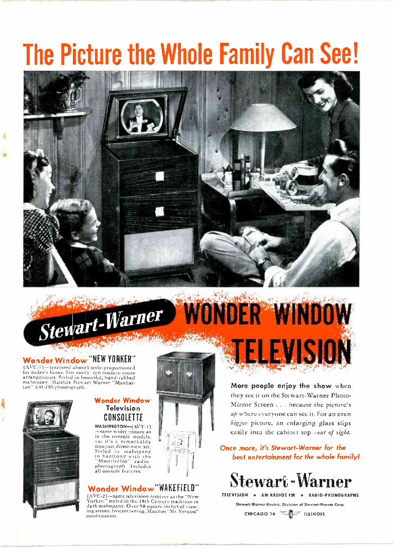
The Picture the Whole Family Can See!
: r. .l
.arn Ste; Wonder Window "NEW YORKER" (AVC-1) -(pictured above) style -proportioned for today's home. Fits easily into modern room arrangements. Styled in beautiful, hand -rubbed mahogany. Matches Stewart -Warner "Manhat- tan" AM -FM -phonograph.
Wonder Window Television
CONSOLETTE WASH INGTON-(AVT- 1 ) -same wider picture as in the console models, yet it's a remarkably compact direct -view set. Styled in mahogany in harmony with the "Monticello" radio - phonograph. Includes all console features.
WONDER WINDOW
VISION
Wonder Window"WAKEFIELD ft
(AVC-2)-same television receiver as the "New Yorker." styled in the 18th Century tradition in dark mahogany. Over 58 square inches of view- ing screen. Instant tuning. Matches "Mt. Vernon" combination.
More people enjoy the show when they see it on the Stewart -Warner Photo - Mirror Screen ... because the picture's up where everyone can see it. For an even bigger picture, an enlarging glass slips easily into the cabinet top-out of sight.
Once more, it's Stewart -Warner for the
best entertainment for the whole family!
Stewart -Warner TELEVISION AM RADIOS FM RADIO -PHONOGRAPHS
Stewart -Warner Electric, Division of Stewart -Warner Corp.
CHICAGO 14 ILLINOIS
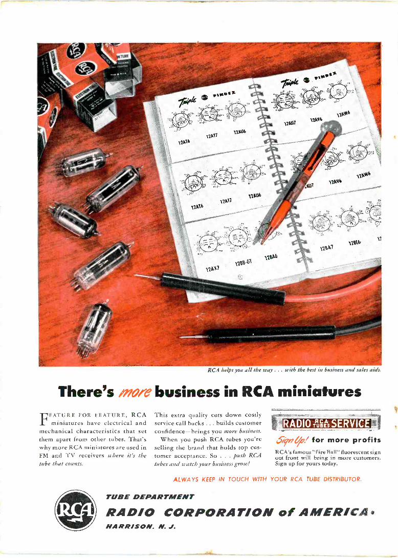
RCA helps you all the way ... with the best in business and sales aids.
There's more business in RCA miniatures FEATURE FOR FEATURE, RCA
miniatures have electrical and mechanical characteristics that set them apart from other tubes. That's why more RCA miniatures are used in FM and TV receivers where it's the tube that counts.
This extra quality cuts down costly service call backs ... builds customer confidence-brings you more business.
When you push RCA tubes you're selling the brand that holds top cus- tomer acceptance. So . . . push RCA
tubes and watch your business grow!
RADIO TRue sSERVICE=
See,' for more profits RCA's famous "Fire Ball" fluorescent sign out front will bring in more customers. Sign up for yours today.
ALWAYS KEEP IN TOUCH WITH YOUR RCA TUBE DISTRIBUTOR.
TUBE DEPARTMENT
RADIO CORPORATION of AMERICA HARRISON. N. J.