Embed Size (px)
Citation preview

Presenter: Deborah Penko, P.E.
Loads in RISA‐3D

RISA‐3D
Joint Loading
Distributed Loading (aka Line Loads)
Point Loading
Area Loading
Surface Loading
Plates
Walls
Moving Loading
Automated Loads‐Wind & Seismic
Agenda

RISA‐3D
Graphical Interface
Windows menu‐ Insert
Basic Load Cases‐ Allows you to access spreadsheets
Overview

RISA‐3D
Spreadsheets
RISA‐3D
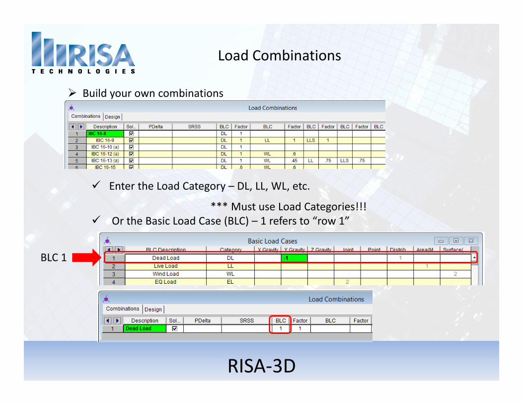
Load Combinations
Build your own combinations
Enter the Load Category – DL, LL, WL, etc.
*** Must use Load Categories!!! Or the Basic Load Case (BLC) – 1 refers to “row 1”
BLC 1

RISA‐3D
Load Combinations
Load Combination can be Nested
8 BLC’s per LC
Combine LC’s
Mix and match LC’s and BLC’s

RISA‐3D
Load Combinations
Or Use the Load Combination Generator
Gravity Loads Wind Loads Seismic Loads

Joint Loads
Apply to any Joint
Load
Global Axis X, Y, Z
Moment MX, MY, MZ
Enforced Displacement
Mass
Directional Mass
Mass Moment of Inertia
Joint Loads

Joint Loads
Enforced Displacement

Distributed Loads
Distributed Loads
Apply Distributed Loads to Members or Walls
Taper loads
Start or Stop anywhere

Distributed Loads
Distributed Loads
X, Y, Z Global Axis
x, y, z Local Axis
Mx Torque about local x‐axis
T Thermal Loading
PX, PY, PZ Projected Loading

Distributed Loads
Thermal Loading
Thermal Loads effects of temperature differentials
Cause the axial expansion or contraction of the member
Ambient Temperature defined:

Distributed Loads
Thermal Loading
For Example: Pre‐Stress Brace Members
7.5 kips Tension Required

Distributed Loads
Thermal Loading
Ft = A * E* α * ΔT
Re‐organized: ΔT = Ft/ (A * E* α)Ft= Calculated Thermal force
Ft= 7.5 kips
A = Member Cross Sectional AreaA = 0.785 in2
E = Elastic ModulusE = 29000ksi
α = Coeff. of Thermal Expansionα = .0000065
Therefore: ΔT = Stress Inducing Temperature
= 50Let’s see this model now!

Distributed Loads
Projected Loading
Projected Load = Applied Load X (Member Length in Horz. Plane)Actual Member Length
100 lb/ft Distributed Load on Y Axis 100 lb/ft Projected PY Load Converts Load 100lb/ft * (10ft/14.1ft)= 70.71
Projected Loads Snow loads

Point Loads
Point Loads
X, Y, Z Global Axis
x, y, z Local Axis
My, Mz Moment about the member local axis
Mx Torsional Moment about local x axis

Area Loads
Area Loading
Define polygon (3 or 4 sides)
Loads applied to Members & Walls
Define One‐Way or Two‐Way Load Attribution

Area Loads
Area Loading
AFirst Click
Second ClickB
Third ClickC
DFourth Click

Area Loads
Area Loading
What is a Transient Area Load?
Let’s take a look at an example model…

Area Loads
Open Structure Loading
Loads applied based on Projected Surface Area
HSS4x4x6width = 4in
Transient Load: 20lbf * 4”/12” = 6.667 lb/ft
Note: Braces don’t get area loads No Shielding
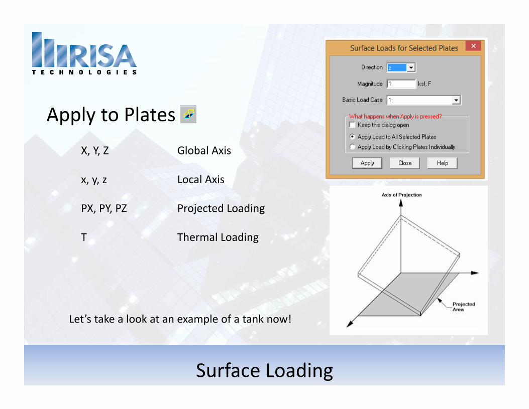
Surface Loading
Apply to PlatesX, Y, Z Global Axis
x, y, z Local Axis
PX, PY, PZ Projected Loading
T Thermal Loading
Let’s take a look at an example of a tank now!

Wall Panel Loads
Wall Panel Loading Options Surface Loading
Full wall or Partial Constant or Tapered force
Distributed Loading
Joint Loading ANYWHERE!
Area Loading

Moving Loading
Moving Loads‐ Two Step Process1. Define the Moving Load Pattern
2. Apply the Moving Load
Let’s take a look at an example!

Wind & Seismic Loading
Automatic Load Generation
Building Design with Rigid Diaphragms Automated Loads

Wind & Seismic Loading
Automatic Load Generation

Presenter: Deborah Penko, P.E.
Please let us know if you have questions.
We will answer as many questions as time permits during the webinar.
Once the webinar is closed, we will post all Q&A’s to our website: www.risa.com
For further information, contact us at: [email protected]
Questions?