Embed Size (px)
Citation preview

CIS/2 Translator
Version 1.0 - General Reference
26632 Towne Centre Drive, Suite 210
Foothill Ranch, California 92610
(949) 951-5815(949) 951-5848 (FAX)
www.risatech.com

Copyright 2009 by RISA Technologies, LLC All rights reserved. No portion of the contents ofthis publication may be reproduced or transmitted in any means without the express written
permission of RISA Technologies, LLC.
We have done our best to insure that the material found in this publication is both useful andaccurate. However, please be aware that errors may exist in this publication, and that RISA
Technologies, LLC makes no guarantees concerning accuracy of the information found here orin the use to which it may be put.
Table of Contents
General Reference Manual I
Table of Contents
Introduction............................................................................................................................ 1
Export mode ......................................................................................................................... 1
Import mode ......................................................................................................................... 1
Cardinal Points ...................................................................................................................... 5
Overview............................................................................................................................... 5
Detailing Input and Modification: .......................................................................................... 6
Visualization of the Detailing Layer ...................................................................................... 9
File I/O ................................................................................................................................ 10
What is Supported with this Translator? .......................................................................... 11
Elements............................................................................................................................. 11
Loading conditions ............................................................................................................. 11
Sections Sets...................................................................................................................... 11
Physical Members and Member mapping.......................................................................... 11
Mapping Files....................................................................................................................... 12
Overwrite and Update Section ........................................................................................... 13
Messages.............................................................................................................................. 14
Supported CIS/2 Entity List (Export) ................................................................................. 15
Supported CIS/2 Entity List (Import).................................................................................. 18
Technical Support ............................................................................................................... 21
Index ..................................................................................................................................... 22

General Reference Manual 1
Introduction
The RISA CIS/2 translator is a tool for transferring data between the RISA-3D program and the CIM steel part 21 fileformat. There are two basic modes for the CIS/2 translator: Export mode and Import mode.
When the user picks “EXPORT” option in the “Translator” group box, the main dialog box will be displayed as export mode.When the user picks the “IMPORT” option in the “Translator” group box, the main dialog box will be displayed as importmode.
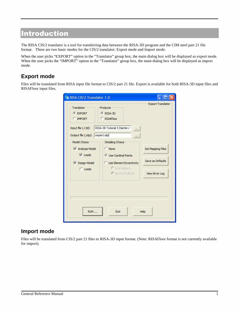
Export mode
Files will be translated from RISA input file format to CIS/2 part 21 file. Export is available for both RISA-3D input files andRISAFloor input files.
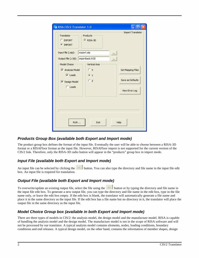
Import mode
Files will be translated from CIS/2 part 21 files to RISA-3D input format. (Note: RISAFloor format is not currently availablefor import).
2 CIS/2 Translator
Products Group Box (available both Export and Import mode)
The product group box defines the format of the input file. Eventually the user will be able to choose between a RISA-3Dformat or a RISAFloor format as the input file. However, RISAFloor import is not supported for the current version of theCIS/2 link. Therefore, only the RISA-3D radio button will appear in the “products” group box in import mode.
Input File (available both Export and Import mode)
An input file can be selected by clicking the button. You can also type the directory and file name in the input file editbox. An input file is required for translation.
Output File (available both Export and Import mode)
To overwrite/update an existing output file, select the file using the button or by typing the directory and file name inthe input file edit box. To generate a new output file, you can type the directory and file name in the edit box, type in the filename only, or leave the edit box empty. If the edit box is blank, the translator will automatically generate a file name andplace it in the same directory as the input file. If the edit box has a file name but no directory in it, the translator will place theoutput file in the same directory as the input file.
Model Choice Group box (available in both Export and Import mode)
There are three types of models in CIS/2: the analysis model, the design model and the manufacture model. RISA is capableof handling the analysis model and the design model. The manufacture model is not in the scope of RISA software and willnot be processed by our translator. A typical analysis model contains elements, nodes, loading conditions, boundaryconditions and end releases. A typical design model, on the other hand, contains the information of member shapes, design
General Reference Manual 3
parts, etc. (Please refer to the entity list section for details). By clicking on the checkbox “design model” and/or “analysismodel”, you choose whether to export a design model, an analysis model, or both. For a complete export for a RISA model, itis recommended to have both the “design model” and “analysis model” selected. Both the CIS/2 design model and theanalysis model contain loads. In most cases, exporting loads in either design or analysis model should be enough. If youchoose to export loads in both design and analysis model when doing the round-trip import from CIS/2 model back to theRISA model, the load will appear doubled. Therefore, it is recommended to write the loads in the analysis model only.
By default, both analysis and design model will be exported, and load will only be exported to the analysis model.
Detailing Choice Group box (available in Export mode only)
The Detailing Choice group box controls the export of member detailing information. There are three options here: None,Use Cardinal Points and Use Element Eccentricity
None
When “none” is selected, no detailing information will be translated in the exported CIS/2 model.
Use Cardinal Points
If the “Use Cardinal Point” option is picked and if the defined connection location falls on a cardinal point, the connectionpoint will be translated as the “cardinal_point” value in the “section_profile” entity for that particular member. For the timebeing, only cardinal point 1 thru 10 is supported in the current version. The “Use Cardinal Point” option is the more popularway for describing the detailing information.
Note:
The connection point needs to fall exactly on a cardinal point location. A cardinal point is stored as a section property for each member. Thus, if you have a brace that is connected at a
different cardinal point at either end, one offset will be lost. It is recommended to "Use Element Eccentricity" in thesecases.
Use Element Eccentricity
If the “Use Element Eccentricity” option is chosen the connection point information is translated to the“element_eccentricity” entity in the CIS/2 model and can later on be further processed by a detailing program like SDS/2.There are two options for “Use Element Eccentricity” selection, “End Pullback” and “No End Pullback”. When the “EndPullback” option is selected, the complete detailing offset will be exported. When the “No End Pullback” option is selected,the detailing offset local y and local z direction (perpendicular to the members) will be exported, the local x offset in themember direction will be 0. (SDS/2 will prefer this option for better handling of data)
The exported detailing information has been tested with SDS/2. By default, “No End Pullback” is selected.
Vertical Axis Group box (available in Import mode only)
In export mode the RISA CIS/2 translator will always export a model with Z as the vertical axis. In import mode, the RISACIS/2 translator will always assume that the .stp file has the global Z as the vertical axis.
RISA-3D and RISAFloor accept the X, Y, or Z axis as the vertical axis, thus when the user is importing a model from theCIS/2 model to RISA format, it is required for the user to define the vertical axis.
When the “X”, “Y”, and “Z” option is selected, the translator will define both the vertical axis of the import model as well asthe member orientation option. When “X” is picked, the vertical axis will be in the global X direction and the default memberorientation will Force member local z axis to be on the YZ plane. When “Y” is picked, the vertical axis will be in the globalY direction and the default member orientation will force member local z axis to be on the XZ plane. When “Z” is picked, the
4 CIS/2 Translator
vertical axis will be in the global Z direction and the default member orientation will Force member local z axis to be on theXY plane.
(For detailed information about vertical axis and member orientation, please refer to “RISA-3D reference manual”)
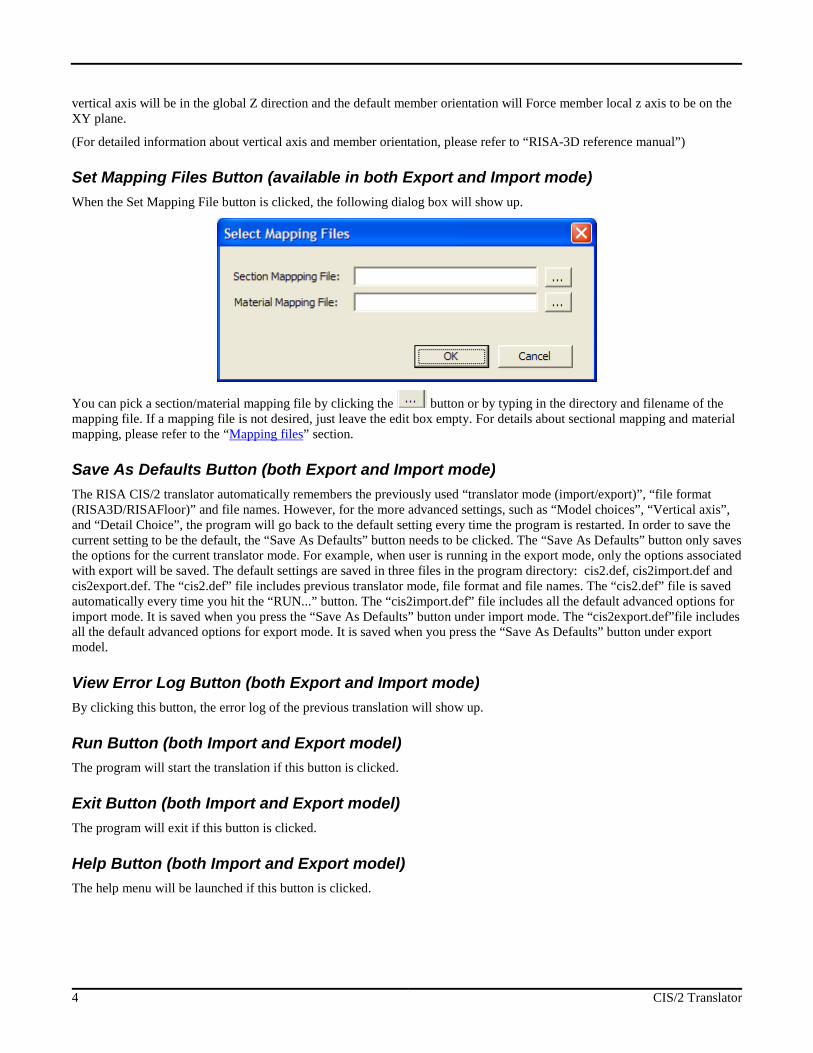
Set Mapping Files Button (available in both Export and Import mode)
When the Set Mapping File button is clicked, the following dialog box will show up.
You can pick a section/material mapping file by clicking the button or by typing in the directory and filename of themapping file. If a mapping file is not desired, just leave the edit box empty. For details about sectional mapping and materialmapping, please refer to the “Mapping files” section.
Save As Defaults Button (both Export and Import mode)
The RISA CIS/2 translator automatically remembers the previously used “translator mode (import/export)”, “file format(RISA3D/RISAFloor)” and file names. However, for the more advanced settings, such as “Model choices”, “Vertical axis”,and “Detail Choice”, the program will go back to the default setting every time the program is restarted. In order to save thecurrent setting to be the default, the “Save As Defaults” button needs to be clicked. The “Save As Defaults” button only savesthe options for the current translator mode. For example, when user is running in the export mode, only the options associatedwith export will be saved. The default settings are saved in three files in the program directory: cis2.def, cis2import.def andcis2export.def. The “cis2.def” file includes previous translator mode, file format and file names. The “cis2.def” file is savedautomatically every time you hit the “RUN...” button. The “cis2import.def” file includes all the default advanced options forimport mode. It is saved when you press the “Save As Defaults” button under import mode. The “cis2export.def”file includesall the default advanced options for export mode. It is saved when you press the “Save As Defaults” button under exportmodel.
View Error Log Button (both Export and Import mode)
By clicking this button, the error log of the previous translation will show up.
Run Button (both Import and Export model)
The program will start the translation if this button is clicked.
Exit Button (both Import and Export model)
The program will exit if this button is clicked.
Help Button (both Import and Export model)
The help menu will be launched if this button is clicked.
General Reference Manual 5
Cardinal Points
Overview
A detailing layer has been built for both 3D and Floor that lets the user set the "true" elevations and locations start/end, top ofsteel, etc...) for all members. For each member (both column and beam in the case of Floor), a new data structure has beenadded to describe the connection point at member ends.
The areas in RISAFloor and RISA-3D where member detailing parameters can be added/viewed are:
RISAFloor Beams Data Entry Spreadsheet>Detailing tab Columns Data Entry Spreadsheet>Detailing tab Plot Options>Beams/Columns/Walls tab
RISA-3D Members Data Entry Spreadsheet>Detailing tab Double-clicking Individual Member>Detailing tab Graphic Member Drawing>Member Detailing tab Plot Options>Members tab
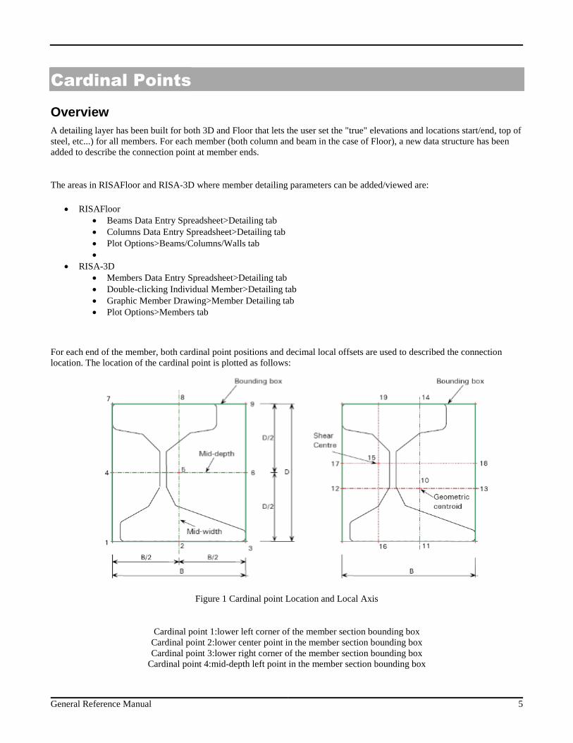
For each end of the member, both cardinal point positions and decimal local offsets are used to described the connectionlocation. The location of the cardinal point is plotted as follows:
Figure 1 Cardinal point Location and Local Axis
Cardinal point 1:lower left corner of the member section bounding boxCardinal point 2:lower center point in the member section bounding boxCardinal point 3:lower right corner of the member section bounding box
Cardinal point 4:mid-depth left point in the member section bounding box
6 CIS/2 Translator
Cardinal point 5:mid-depth center point in the member section bounding boxCardinal point 6:mid-depth right point in the member section bounding box
Cardinal point 7:upper left corner of the member section bounding boxCardinal point 8:upper center point in the member section bounding boxCardinal point 9:upper right corner of the member section bounding box
Cardinal point 10:Geometric centroid of the member sectionNote:
Only cardinal point 1-10 are supported by RISA. You may instead use an offset.
The x, y, and z offsets are based on the local axis of the member. The x local axis is defined along the member from I to J. Itcoincides with the geometric centroid of the member section. The standard cardinal point positions (1-10), as well as thedecimal local offsets are both supported in current detailing definition. If the cardinal point is set, the y and z offset valueswill be automatically calculated and filled in the data structure. If there is a situation that doesn't match a cardinal point (anglebrace as an example) you can also set the y and z offsets directly.
Note:
The TOM and Rigid End Offset are completely different concepts from the detailing offset. The purpose of thedetailing offsets is more realistic visualization and plotting of the model. The detailing offsets are not consideredduring the analysis. In the analysis, all members are still connected at their geometric centroid. TOM and Rigid EndOffsets, on the other hand, affect the load distribution and design of the member. They are analysis parameters. In ourprogram, the TOM / Rigid End Offset are completely separate data structure from the detailing offsets. When TOM isset for a model, for example, the detailing information will NOT be automatically updated to cardinal point 8accordingly.
Detailing Input and Modification:
There are three ways for setting and modifying the detailing layer information. User can use the graphical member modify,the double-click dialog and the member detailing spreadsheet to set the detailing information.
Default
When a member is drawn, by default, x offsets are set to be 0 on both ends. If the member type is beam , by default the y andz detailing offsets will be on cardinal point 8 ( top center) for both ends. If the member type is column, by default thedetailing offset will be on cardinal point 10 for both ends.
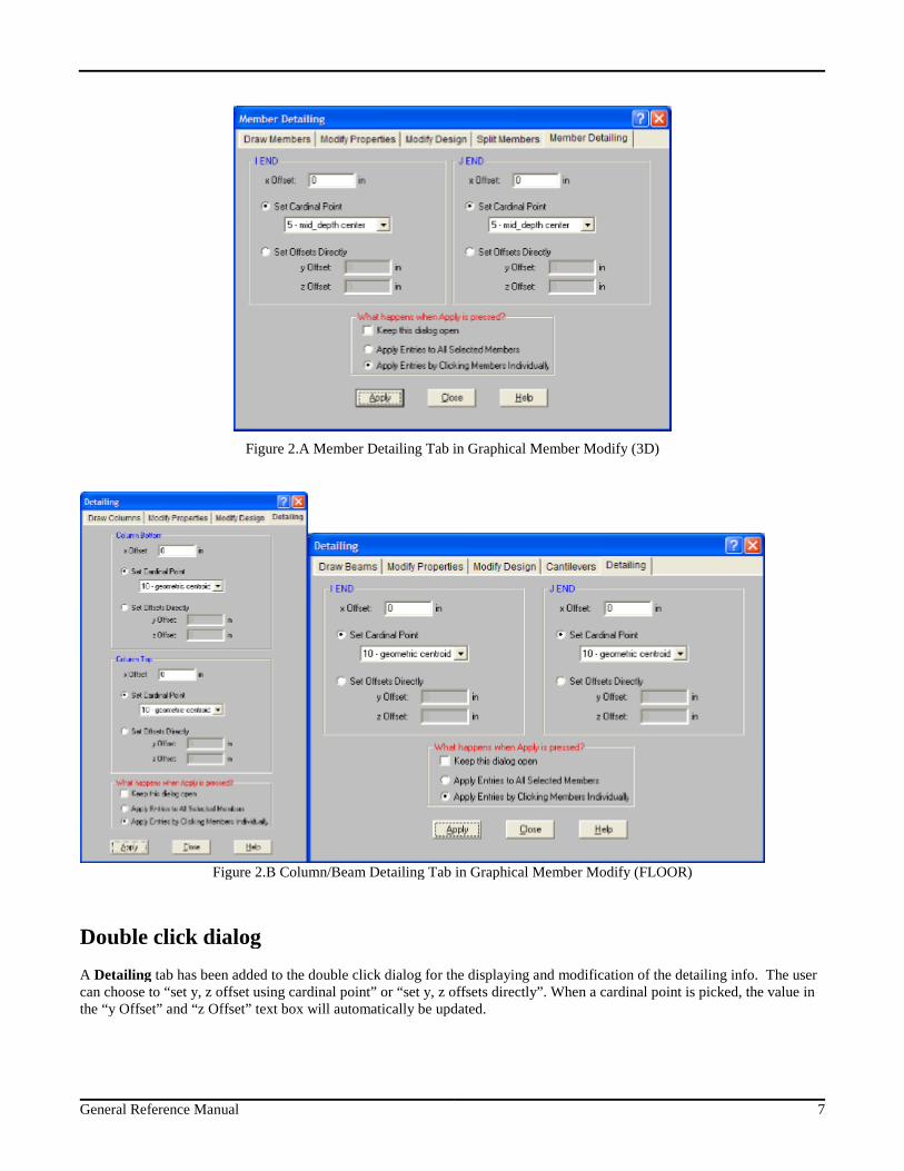
Graphical member modify
A Member Detailing tab has been added to the Graphical member draw/modify window. The user can choose to “set y, zoffset using cardinal point” or “set y, z offsets directly”. When a cardinal point is picked, the value in the “y Offset” and “zOffset” text box will automatically be updated.
General Reference Manual 7
Figure 2.A Member Detailing Tab in Graphical Member Modify (3D)
Figure 2.B Column/Beam Detailing Tab in Graphical Member Modify (FLOOR)
Double click dialog
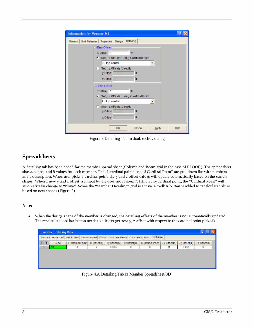
A Detailing tab has been added to the double click dialog for the displaying and modification of the detailing info. The usercan choose to “set y, z offset using cardinal point” or “set y, z offsets directly”. When a cardinal point is picked, the value inthe “y Offset” and “z Offset” text box will automatically be updated.
8 CIS/2 Translator
Figure 3 Detailing Tab in double click dialog
Spreadsheets
A detailing tab has been added for the member spread sheet (Column and Beam grid in the case of FLOOR). The spreadsheetshows a label and 8 values for each member. The “I cardinal point” and “J Cardinal Point” are pull down list with numbersand a description. When user picks a cardinal point, the y and z offset values will update automatically based on the currentshape. When a new y and z offset are input by the user and it doesn’t fall on any cardinal point, the “Cardinal Point” willautomatically change to “None”. When the “Member Detailing” grid is active, a toolbar button is added to recalculate valuesbased on new shapes (Figure 5).
Note:
When the design shape of the member is changed, the detailing offsets of the member is not automatically updated.The recalculate tool bar button needs to click to get new y, z offset with respect to the cardinal point picked)
Figure 4.A Detailing Tab in Member Spreadsheet(3D)
General Reference Manual 9
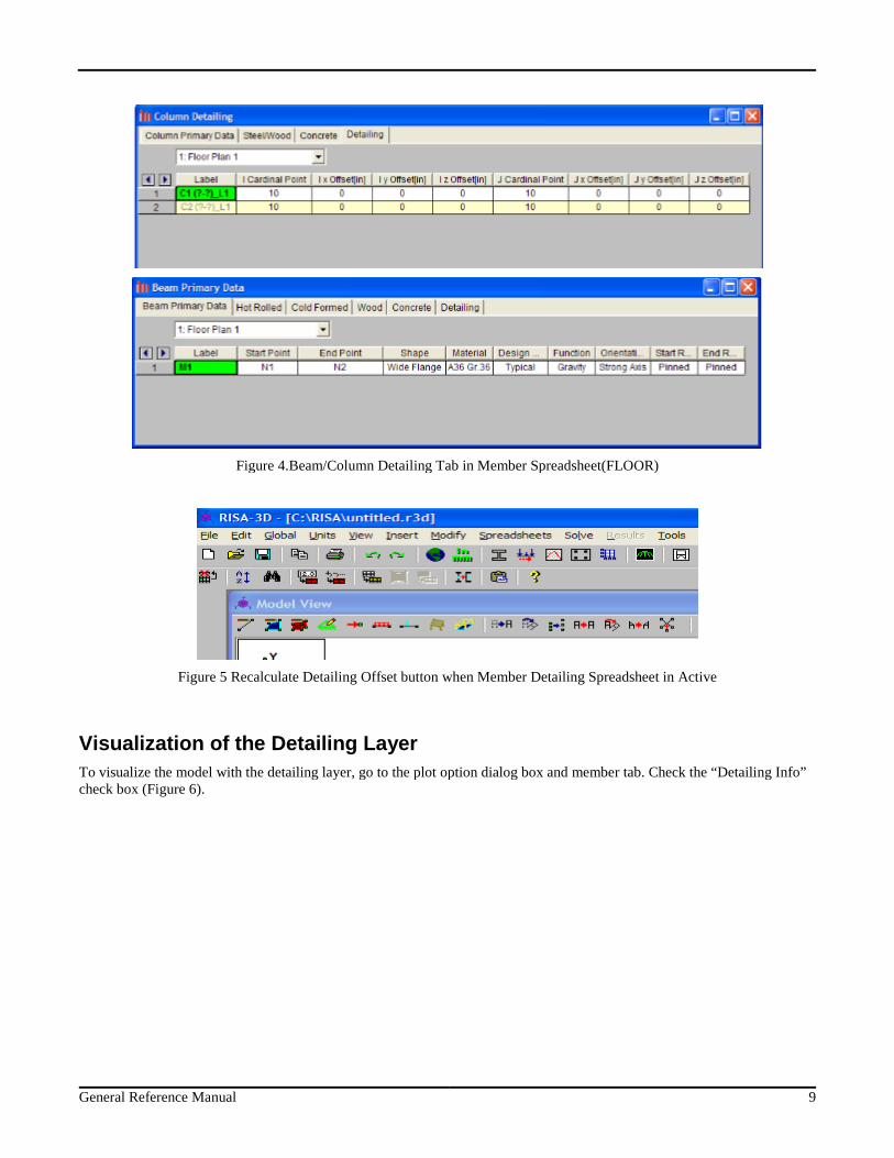
Figure 4.Beam/Column Detailing Tab in Member Spreadsheet(FLOOR)
Figure 5 Recalculate Detailing Offset button when Member Detailing Spreadsheet in Active
Visualization of the Detailing Layer
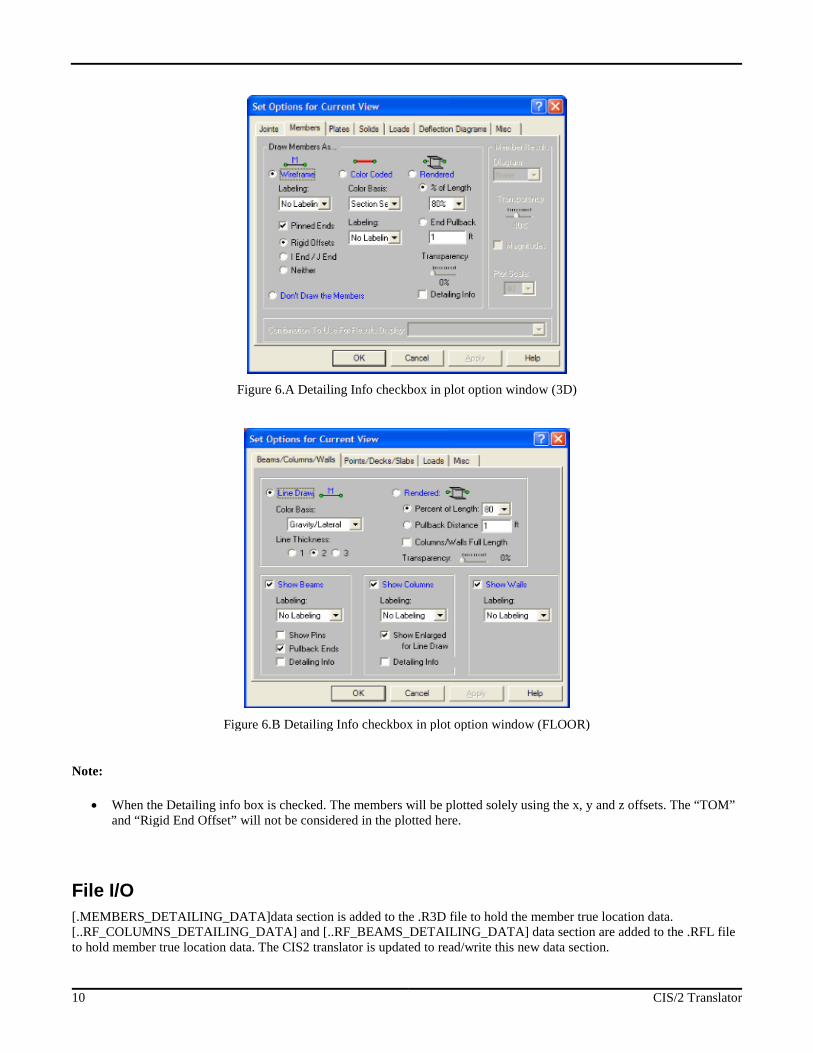
To visualize the model with the detailing layer, go to the plot option dialog box and member tab. Check the “Detailing Info”check box (Figure 6).
10 CIS/2 Translator
Figure 6.A Detailing Info checkbox in plot option window (3D)
Figure 6.B Detailing Info checkbox in plot option window (FLOOR)
Note:
When the Detailing info box is checked. The members will be plotted solely using the x, y and z offsets. The “TOM”and “Rigid End Offset” will not be considered in the plotted here.
File I/O
[.MEMBERS_DETAILING_DATA]data section is added to the .R3D file to hold the member true location data.[..RF_COLUMNS_DETAILING_DATA] and [..RF_BEAMS_DETAILING_DATA] data section are added to the .RFL fileto hold member true location data. The CIS2 translator is updated to read/write this new data section.
General Reference Manual 11
What is Supported with this Translator?
Elements
Only member elements are supported with the CIS/2 translator. Plate and solid elements are not supported in the currentversion.
Loading conditions
The current CIS/2 translator only supports joint loads, member concentrated loads and member distributed loads. Memberarea loads and plate surface loads are not supported. In the current version, only static loads will be considered in thetranslation. Dynamic loading in the model will be ignored. RISA joint loads can be defined in the form of mass, displacementand forces. During the translation, only the force type of load will be translated. The mass and displacement loads will beignored.
Sections Sets
CIS/2 does not understand the concept of section set. Therefore, in order to export the model correctly, members need to beexplicitly defined with a shape name.
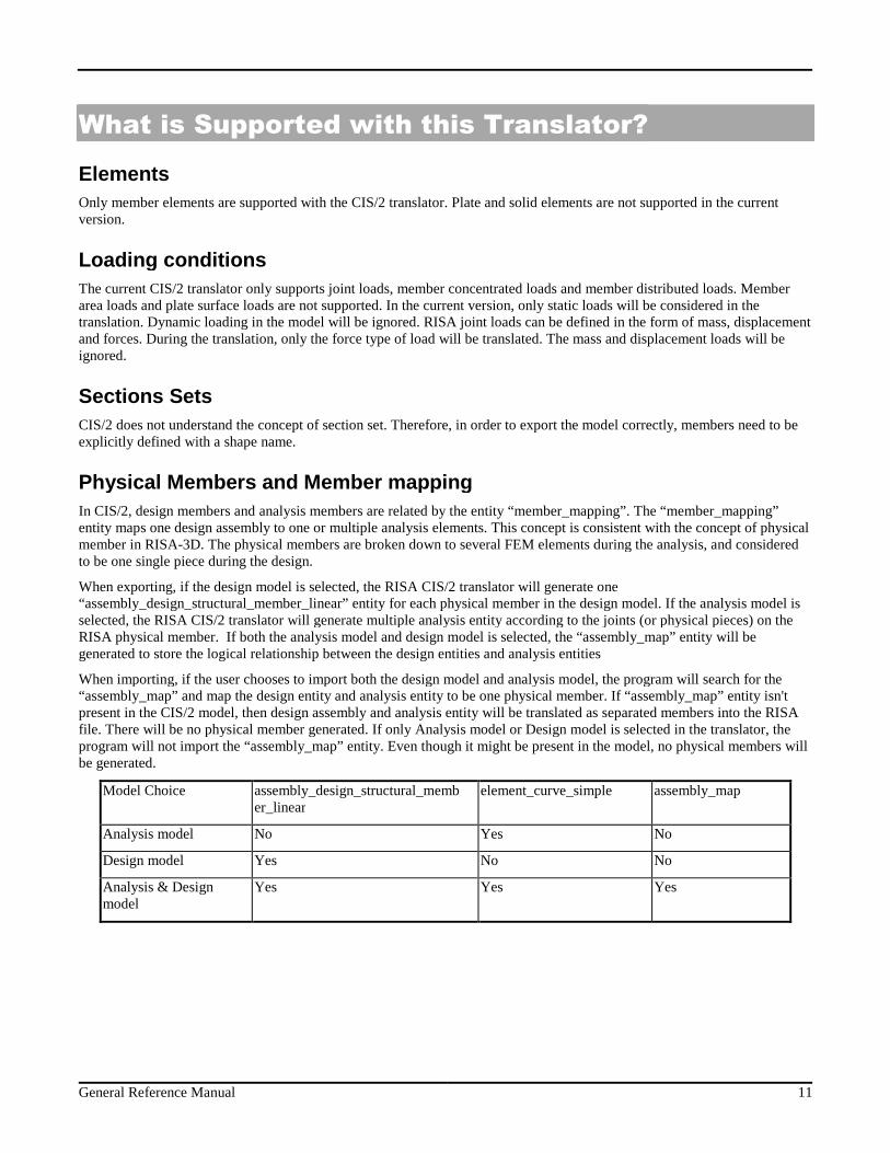
Physical Members and Member mapping
In CIS/2, design members and analysis members are related by the entity “member_mapping”. The “member_mapping”entity maps one design assembly to one or multiple analysis elements. This concept is consistent with the concept of physicalmember in RISA-3D. The physical members are broken down to several FEM elements during the analysis, and consideredto be one single piece during the design.
When exporting, if the design model is selected, the RISA CIS/2 translator will generate one“assembly_design_structural_member_linear” entity for each physical member in the design model. If the analysis model isselected, the RISA CIS/2 translator will generate multiple analysis entity according to the joints (or physical pieces) on theRISA physical member. If both the analysis model and design model is selected, the “assembly_map” entity will begenerated to store the logical relationship between the design entities and analysis entities
When importing, if the user chooses to import both the design model and analysis model, the program will search for the“assembly_map” and map the design entity and analysis entity to be one physical member. If “assembly_map” entity isn'tpresent in the CIS/2 model, then design assembly and analysis entity will be translated as separated members into the RISAfile. There will be no physical member generated. If only Analysis model or Design model is selected in the translator, theprogram will not import the “assembly_map” entity. Even though it might be present in the model, no physical members willbe generated.
Model Choice assembly_design_structural_member_linear
element_curve_simple assembly_map
Analysis model No Yes No
Design model Yes No No
Analysis & Designmodel
Yes Yes Yes
12 CIS/2 Translator
Mapping Files
Different programs have their own naming convention for materials and shapes. For example, the angle section“LL8X8X18X0” in RISA, is named “2L8x8x1 1/8” in SDS2, and is named “2L8x8x1-1/8” in SmartPlant3D. Mapping filesare used for this purpose. If a section mapping file is provided during export, the translator will search the mapping file forthe corresponding name of the objective program, and use the new name in the CIS/2 part21 file. During import, thetranslator will search the mapping file for the RISA shape name and write the RISA file. If the mapping file is not providedby the user, the original section name will be written by the translator.
Sample section and material mapping files with SmartPlant3D and SDS/2 are provided with the RISA CIS/2 translatorpackage. Both the section mapping and the material mapping file is of XML format. Using the provided mapping files astemplate, you can write your own mapping files if communication with a third party program is desired.
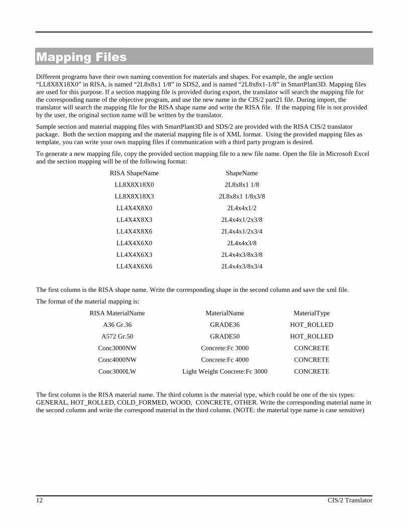
To generate a new mapping file, copy the provided section mapping file to a new file name. Open the file in Microsoft Exceland the section mapping will be of the following format:
RISA ShapeName ShapeName
LL8X8X18X0 2L8x8x1 1/8
LL8X8X18X3 2L8x8x1 1/8x3/8
LL4X4X8X0 2L4x4x1/2
LL4X4X8X3 2L4x4x1/2x3/8
LL4X4X8X6 2L4x4x1/2x3/4
LL4X4X6X0 2L4x4x3/8
LL4X4X6X3 2L4x4x3/8x3/8
LL4X4X6X6 2L4x4x3/8x3/4
The first column is the RISA shape name. Write the corresponding shape in the second column and save the xml file.
The format of the material mapping is:
RISA MaterialName MaterialName MaterialType
A36 Gr.36 GRADE36 HOT_ROLLED
A572 Gr.50 GRADE50 HOT_ROLLED
Conc3000NW Concrete:Fc 3000 CONCRETE
Conc4000NW Concrete:Fc 4000 CONCRETE
Conc3000LW Light Weight Concrete:Fc 3000 CONCRETE
The first column is the RISA material name. The third column is the material type, which could be one of the six types:GENERAL, HOT_ROLLED, COLD_FORMED, WOOD, CONCRETE, OTHER. Write the corresponding material name inthe second column and write the correspond material in the third column. (NOTE: the material type name is case sensitive)
General Reference Manual 13
Overwrite and Update Section
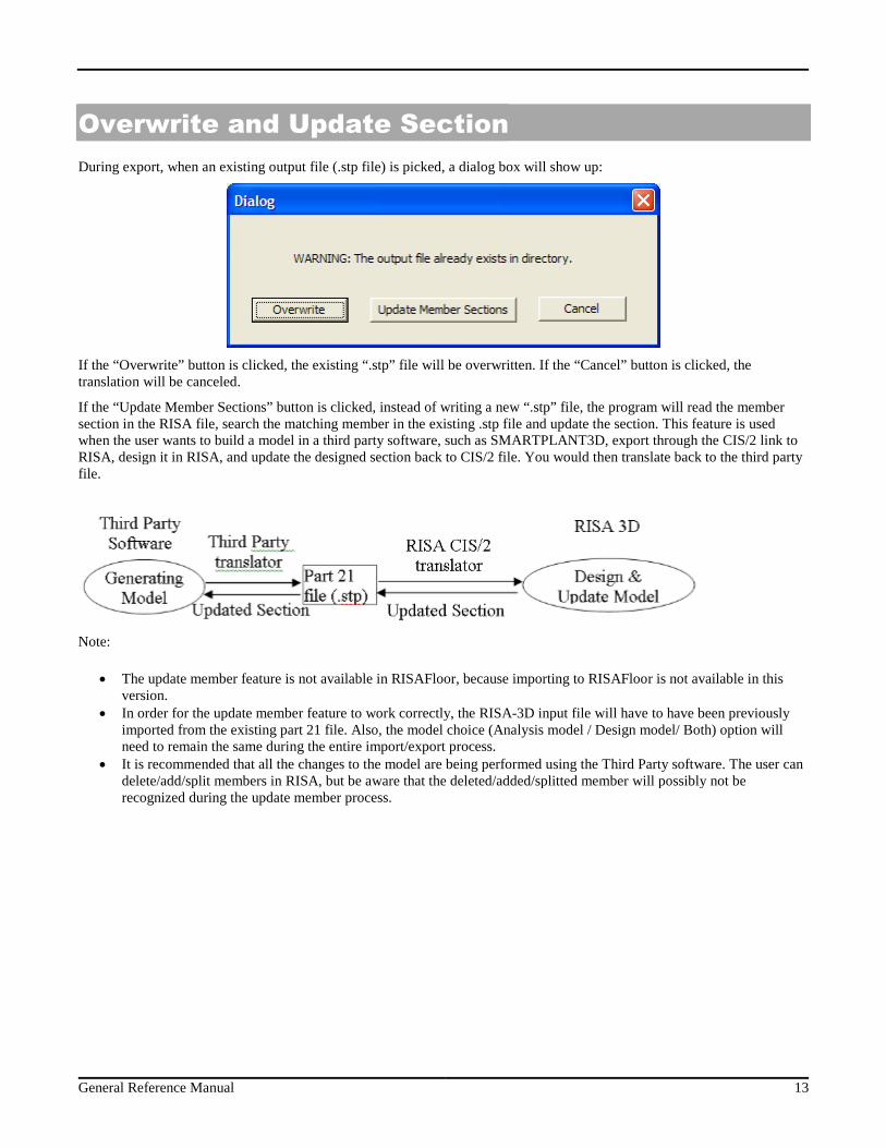
During export, when an existing output file (.stp file) is picked, a dialog box will show up:
If the “Overwrite” button is clicked, the existing “.stp” file will be overwritten. If the “Cancel” button is clicked, thetranslation will be canceled.
If the “Update Member Sections” button is clicked, instead of writing a new “.stp” file, the program will read the membersection in the RISA file, search the matching member in the existing .stp file and update the section. This feature is usedwhen the user wants to build a model in a third party software, such as SMARTPLANT3D, export through the CIS/2 link toRISA, design it in RISA, and update the designed section back to CIS/2 file. You would then translate back to the third partyfile.
Note:
The update member feature is not available in RISAFloor, because importing to RISAFloor is not available in thisversion.
In order for the update member feature to work correctly, the RISA-3D input file will have to have been previouslyimported from the existing part 21 file. Also, the model choice (Analysis model / Design model/ Both) option willneed to remain the same during the entire import/export process.
It is recommended that all the changes to the model are being performed using the Third Party software. The user candelete/add/split members in RISA, but be aware that the deleted/added/splitted member will possibly not berecognized during the update member process.
14 CIS/2 Translator
Messages
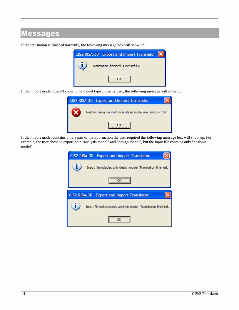
If the translation is finished normally, the following message box will show up:
If the import model doesn’t contain the model type chose by user, the following message will show up:
If the import model contains only a part of the information the user required the following message box will show up. Forexample, the user chose to export both “analysis model” and “design model”, but the input file contains only “analysismodel”
General Reference Manual 15
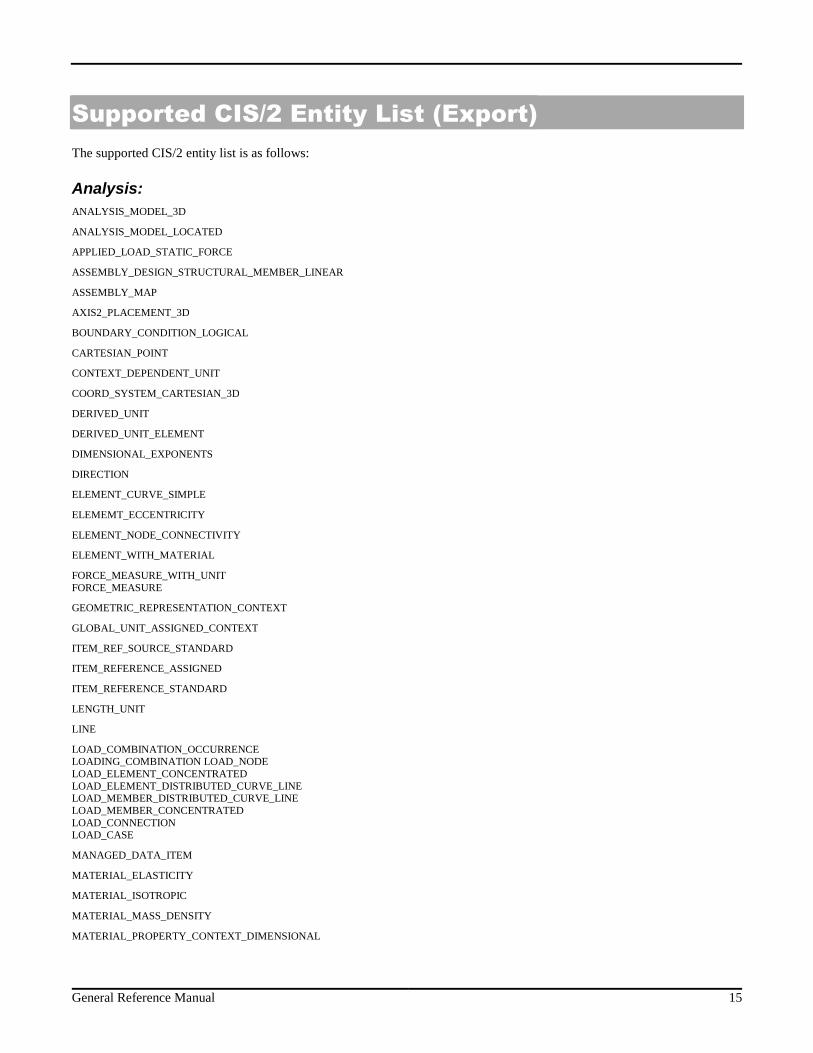
Supported CIS/2 Entity List (Export)
The supported CIS/2 entity list is as follows:
Analysis:
ANALYSIS_MODEL_3D
ANALYSIS_MODEL_LOCATED
APPLIED_LOAD_STATIC_FORCE
ASSEMBLY_DESIGN_STRUCTURAL_MEMBER_LINEAR
ASSEMBLY_MAP
AXIS2_PLACEMENT_3D
BOUNDARY_CONDITION_LOGICAL
CARTESIAN_POINT
CONTEXT_DEPENDENT_UNIT
COORD_SYSTEM_CARTESIAN_3D
DERIVED_UNIT
DERIVED_UNIT_ELEMENT
DIMENSIONAL_EXPONENTS
DIRECTION
ELEMENT_CURVE_SIMPLE
ELEMEMT_ECCENTRICITY
ELEMENT_NODE_CONNECTIVITY
ELEMENT_WITH_MATERIAL
FORCE_MEASURE_WITH_UNITFORCE_MEASURE
GEOMETRIC_REPRESENTATION_CONTEXT
GLOBAL_UNIT_ASSIGNED_CONTEXT
ITEM_REF_SOURCE_STANDARD
ITEM_REFERENCE_ASSIGNED
ITEM_REFERENCE_STANDARD
LENGTH_UNIT
LINE
LOAD_COMBINATION_OCCURRENCELOADING_COMBINATION LOAD_NODELOAD_ELEMENT_CONCENTRATEDLOAD_ELEMENT_DISTRIBUTED_CURVE_LINELOAD_MEMBER_DISTRIBUTED_CURVE_LINELOAD_MEMBER_CONCENTRATEDLOAD_CONNECTIONLOAD_CASE
MANAGED_DATA_ITEM
MATERIAL_ELASTICITY
MATERIAL_ISOTROPIC
MATERIAL_MASS_DENSITY
MATERIAL_PROPERTY_CONTEXT_DIMENSIONAL
16 CIS/2 Translator
MATERIAL_REPRESENTATION
MATERIAL_STRENGTH
MATERIAL_THERMAL_EXPANSION
NODE
ORGANIZATION
PHYSICAL_ACTION_PERMANENT
PLANE_ANGLE_MEASURE
PLANE_ANGLE_MEASURE_WITH_UNIT
PLANE_ANGLE_UNIT
PRESSURE_UNIT
RELEASE_LOGICAL
REPRESENTATION
SECTION_PROFILE
SI_UNIT
VECTOR
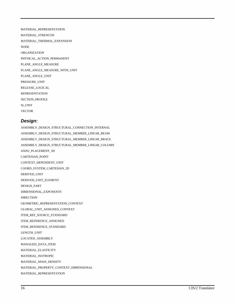
Design:
ASSEMBLY_DESIGN_STRUCTURAL_CONNECTION_INTERNAL
ASSEMBLY_DESIGN_STRUCTURAL_MEMBER_LINEAR_BEAM
ASSEMBLY_DESIGN_STRUCTURAL_MEMBER_LINEAR_BRACE
ASSEMBLY_DESIGN_STRUCTURAL_MEMBER_LINEAR_COLUMN
AXIS2_PLACEMENT_3D
CARTESIAN_POINT
CONTEXT_DEPENDENT_UNIT
COORD_SYSTEM_CARTESIAN_3D
DERIVED_UNIT
DERIVED_UNIT_ELEMENT
DESIGN_PART
DIMENSIONAL_EXPONENTS
DIRECTION
GEOMETRIC_REPRESENTATION_CONTEXT
GLOBAL_UNIT_ASSIGNED_CONTEXT
ITEM_REF_SOURCE_STANDARD
ITEM_REFERENCE_ASSIGNED
ITEM_REFERENCE_STANDARD
LENGTH_UNIT
LOCATED_ASSEMBLY
MANAGED_DATA_ITEM
MATERIAL_ELASTICITY
MATERIAL_ISOTROPIC
MATERIAL_MASS_DENSITY
MATERIAL_PROPERTY_CONTEXT_DIMENSIONAL
MATERIAL_REPRESENTATION
General Reference Manual 17
MATERIAL_STRENGTH
MATERIAL_THERMAL_EXPANSION
ORGANIZATION
PART_PRISMATIC_SIMPLE
POSITIVE_LENGTH_MEASURE
POSITIVE_LENGTH_MEASURE_WITH_UNIT
PRESSURE_UNIT
REPRESENTATION
SECTION_PROFILE
SI_UNIT
STRUCTURAL_FRAME_PRODUCT_WITH_MATERIAL
STRUCTURE
18 CIS/2 Translator
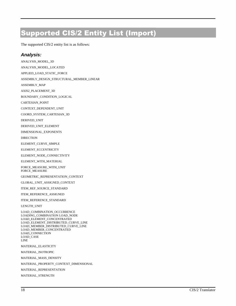
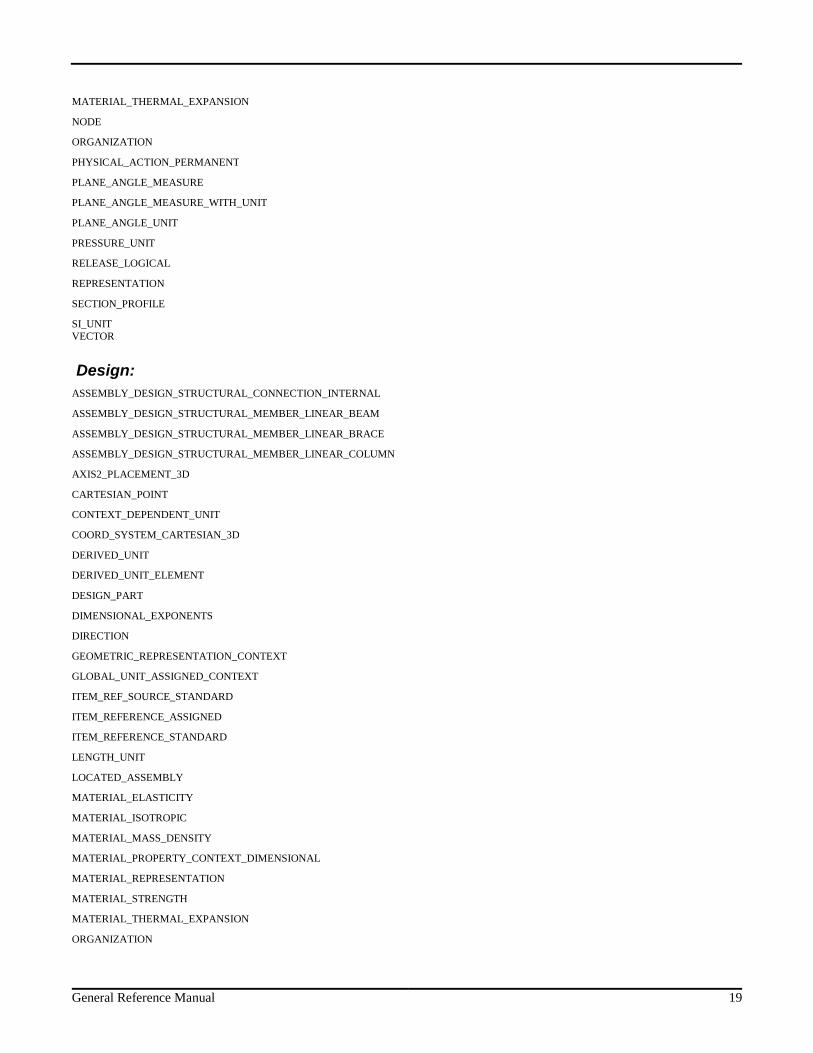
Supported CIS/2 Entity List (Import)
The supported CIS/2 entity list is as follows:
Analysis:
ANALYSIS_MODEL_3D
ANALYSIS_MODEL_LOCATED
APPLIED_LOAD_STATIC_FORCE
ASSEMBLY_DESIGN_STRUCTURAL_MEMBER_LINEAR
ASSEMBLY_MAP
AXIS2_PLACEMENT_3D
BOUNDARY_CONDITION_LOGICAL
CARTESIAN_POINT
CONTEXT_DEPENDENT_UNIT
COORD_SYSTEM_CARTESIAN_3D
DERIVED_UNIT
DERIVED_UNIT_ELEMENT
DIMENSIONAL_EXPONENTS
DIRECTION
ELEMENT_CURVE_SIMPLE
ELEMENT_ECCENTRICITY
ELEMENT_NODE_CONNECTIVITY
ELEMENT_WITH_MATERIAL
FORCE_MEASURE_WITH_UNITFORCE_MEASURE
GEOMETRIC_REPRESENTATION_CONTEXT
GLOBAL_UNIT_ASSIGNED_CONTEXT
ITEM_REF_SOURCE_STANDARD
ITEM_REFERENCE_ASSIGNED
ITEM_REFERENCE_STANDARD
LENGTH_UNIT
LOAD_COMBINATION_OCCURRENCELOADING_COMBINATION LOAD_NODELOAD_ELEMENT_CONCENTRATEDLOAD_ELEMENT_DISTRIBUTED_CURVE_LINELOAD_MEMBER_DISTRIBUTED_CURVE_LINELOAD_MEMBER_CONCENTRATEDLOAD_CONNECTIONLOAD_CASELINE
MATERIAL_ELASTICITY
MATERIAL_ISOTROPIC
MATERIAL_MASS_DENSITY
MATERIAL_PROPERTY_CONTEXT_DIMENSIONAL
MATERIAL_REPRESENTATION
MATERIAL_STRENGTH
General Reference Manual 19
MATERIAL_THERMAL_EXPANSION
NODE
ORGANIZATION
PHYSICAL_ACTION_PERMANENT
PLANE_ANGLE_MEASURE
PLANE_ANGLE_MEASURE_WITH_UNIT
PLANE_ANGLE_UNIT
PRESSURE_UNIT
RELEASE_LOGICAL
REPRESENTATION
SECTION_PROFILE
SI_UNITVECTOR
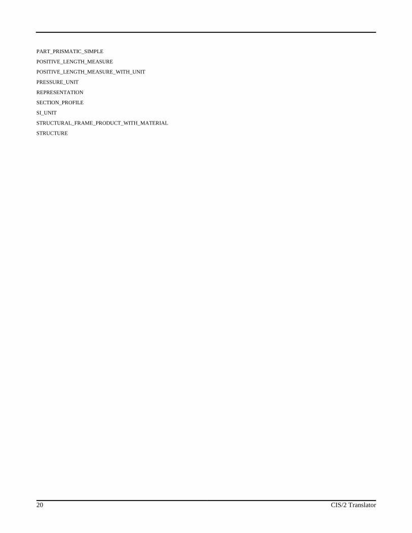
Design:
ASSEMBLY_DESIGN_STRUCTURAL_CONNECTION_INTERNAL
ASSEMBLY_DESIGN_STRUCTURAL_MEMBER_LINEAR_BEAM
ASSEMBLY_DESIGN_STRUCTURAL_MEMBER_LINEAR_BRACE
ASSEMBLY_DESIGN_STRUCTURAL_MEMBER_LINEAR_COLUMN
AXIS2_PLACEMENT_3D
CARTESIAN_POINT
CONTEXT_DEPENDENT_UNIT
COORD_SYSTEM_CARTESIAN_3D
DERIVED_UNIT
DERIVED_UNIT_ELEMENT
DESIGN_PART
DIMENSIONAL_EXPONENTS
DIRECTION
GEOMETRIC_REPRESENTATION_CONTEXT
GLOBAL_UNIT_ASSIGNED_CONTEXT
ITEM_REF_SOURCE_STANDARD
ITEM_REFERENCE_ASSIGNED
ITEM_REFERENCE_STANDARD
LENGTH_UNIT
LOCATED_ASSEMBLY
MATERIAL_ELASTICITY
MATERIAL_ISOTROPIC
MATERIAL_MASS_DENSITY
MATERIAL_PROPERTY_CONTEXT_DIMENSIONAL
MATERIAL_REPRESENTATION
MATERIAL_STRENGTH
MATERIAL_THERMAL_EXPANSION
ORGANIZATION
20 CIS/2 Translator
PART_PRISMATIC_SIMPLE
POSITIVE_LENGTH_MEASURE
POSITIVE_LENGTH_MEASURE_WITH_UNIT
PRESSURE_UNIT
REPRESENTATION
SECTION_PROFILE
SI_UNIT
STRUCTURAL_FRAME_PRODUCT_WITH_MATERIAL
STRUCTURE
General Reference Manual 21
Technical Support
Technical support is very important to the staff at RISA Technologies. We want our users to be able to reach us when theyare having difficulties with the program. However, this service is not to be used as a way to avoid learning the program orlearning how to perform structural modeling in general.
Hours: 6AM to 5PM Pacific Standard Time, Monday through Friday
Before contacting technical support, you should typically do the following:
1. Please search the Help File or General Reference Manual. Most questions asked about CIS/2 translator are alreadyanswered in the Help File or General Reference Manual. Use the table of contents or index to find specific topics andappropriate sections. We go to great lengths to provide extensive written and on-line documentation for theprogram. We do this in order to help you understand the features and make them easier to use.
2. If you have access to the Internet, you can visit our website at www.risatech.com and check out our Support sectionfor release notes, updates, downloads, and frequently asked questions. We list known issues and product updates thatyou can download. So, if you think the program is in error you should see if the problem is listed and make sure youhave the latest release. The FAQ (Frequently Asked Questions) section may also address your question.
3. Make sure you understand the problem, and make sure your question is related to the program or structural modeling.Technical Support does not include free engineering consulting. RISA Technologies does provide a consultingservice. If you are interested in inquiring about this service, please call RISA Technologies.
4. Take a few minutes to experiment with the problem to try to understand and solve it.
Email: [email protected]: Make sure you tell us your name, company name, serial number or Key ID, phone number,and give a decent problem description.
Phone Support:(949) 951-5815: Feel free to call, especially if you need a quick answer and your question is not modelspecific and therefore doesn't require us to look at your file.
22 CIS/2 Translator
Index
C
Cardinal Point Locations, 5
Cardinal Points, 5
D
Detailing Input, 6
Detailing Layer, 5
Detailing Modification, 6
Double click dialog, 7
E
Element, 12
Element Eccentricity Group box, 3
Exit, 4
Export Mode, 1
F
File I/O, 11
G
Graphical Member Modify, 6
H
Help Button, 4
I
Import mode, 1
Input File, 2
Introduction, 1
L
Loading Conditions, 12
M
Mapping Files, 13
Messages, 15
Model Choice Group box, 2
O
Output File, 2
Overview, 5
Overwrite, 14
P
Physical Member, 12
Products Group Box, 2
R
Run, 4
S
Save As Defaults, 4
Sections Sets, 12
Set Mapping Files, 4
Supported CIS/2 Entity List, 16, 19
T
Technical Support, 22
U
Update Section, 14
V
Vertical Axis Group box, 3
View Error Log, 4