Embed Size (px)
Citation preview

RISA-3D Rapid Interactive Structural Analysis – 3-Dimensional
Version 7.1 User’s Guide
26632 Towne Centre Drive, Suite 210 Foothill Ranch, California 92610 (949) 951-5815 (949) 951-5848 (FAX) www.risatech.com

Copyright 2008 by RISA Technologies, LLC. All rights reserved.
No portion of the contents of this publication may be reproduced or transmitted in any means without the express written permission of RISA Technologies.
We have done our best to insure that the material found in this publication is both useful and accurate. However, please be aware that errors may exist in this publication, and that RISA Technologies makes no guarantees concerning accuracy
of the information found here or in the use to which it may be put.

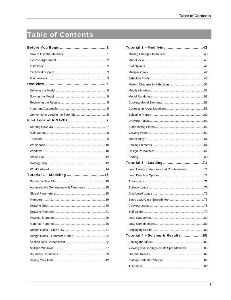
Table of Contents
I
Table of Contents Before You Begin .........................................1
How to Use the Manuals.................................................... 1 License Agreement............................................................ 2 Installation.......................................................................... 3 Technical Support.............................................................. 3 Maintenance ...................................................................... 3
Overview ......................................................5 Defining the Model............................................................. 5 Solving the Model .............................................................. 5 Reviewing the Results ....................................................... 5 Important Assumption!....................................................... 5 Conventions Used in the Tutorials..................................... 5
First Look at RISA-3D ..................................7 Starting RISA-3D ............................................................... 7 Main Menu ......................................................................... 8 Toolbars............................................................................. 9 Workspace....................................................................... 10 Windows .......................................................................... 10 Status Bar ........................................................................ 12 Getting Help..................................................................... 12 What’s Ahead .................................................................. 14
Tutorial 1 – Modeling .................................15 Starting a New File .......................................................... 15 Automatically Generating with Templates ....................... 15 Global Parameters........................................................... 15 Members.......................................................................... 19 Drawing Grid.................................................................... 20 Drawing Members............................................................ 21 Physical Members ........................................................... 29 Material Properties........................................................... 30 Design Rules – Size / UC ................................................ 31 Design Rules – Concrete Rebar ...................................... 32 Section Sets Spreadsheet ............................................... 32 Multiple Windows............................................................. 37 Boundary Conditions ....................................................... 39 Saving Your Data............................................................. 42
Tutorial 2 – Modifying ................................43 Making Changes to an Item .............................................43 Model View.......................................................................45 Plot Options......................................................................47 Multiple Views ..................................................................47 Selection Tools.................................................................48 Making Changes to Selections.........................................51 Modify Members...............................................................51 Model Rendering..............................................................53 Copying Model Elements .................................................53 Connecting Along Members.............................................55 Selecting Planes ..............................................................60 Drawing Plates .................................................................61 Submeshing Plates ..........................................................61 Viewing Plates..................................................................63 Model Merge ....................................................................64 Scaling Elements .............................................................64 Design Parameters ..........................................................67 Sorting..............................................................................68
Tutorial 3 – Loading ...................................71 Load Cases, Categories and Combinations.....................71 Load Direction Options.....................................................72 Area Loads.......................................................................72 Surface Loads ..................................................................76 Distributed Loads .............................................................76 Basic Load Case Spreadsheet.........................................78 Copying Loads .................................................................78 Self-weight .......................................................................79 Load Categories...............................................................80 Load Combinations ..........................................................80 Displaying Loads..............................................................83
Tutorial 4 – Solving & Results ...................85 Solving the Model.............................................................85 Viewing and Sorting Results Spreadsheets .....................86 Graphic Results................................................................87 Plotting Deflected Shapes................................................87 Animation .........................................................................88
RISA-3D User’s Guide
II
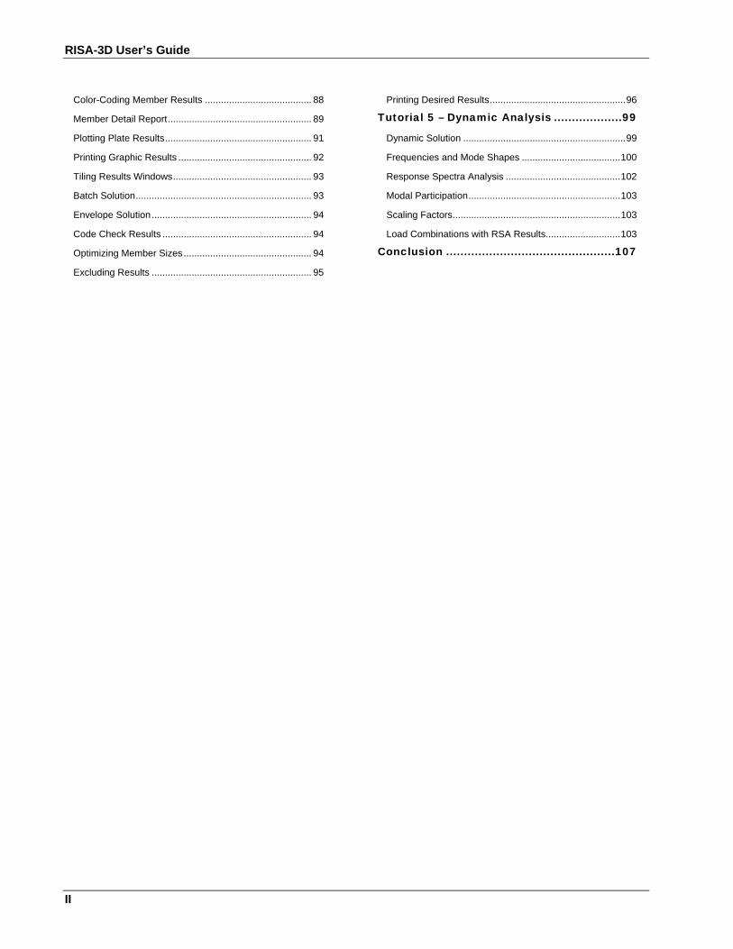
Color-Coding Member Results ........................................ 88 Member Detail Report...................................................... 89 Plotting Plate Results....................................................... 91 Printing Graphic Results .................................................. 92 Tiling Results Windows.................................................... 93 Batch Solution.................................................................. 93 Envelope Solution............................................................ 94 Code Check Results ........................................................ 94 Optimizing Member Sizes................................................ 94 Excluding Results ............................................................ 95
Printing Desired Results...................................................96 Tutorial 5 – Dynamic Analysis ...................99
Dynamic Solution .............................................................99 Frequencies and Mode Shapes .....................................100 Response Spectra Analysis ...........................................102 Modal Participation.........................................................103 Scaling Factors...............................................................103 Load Combinations with RSA Results............................103
Conclusion ...............................................107
Before You Begin
1
Before You Begin
How to Use the Manuals This Guide is designed to be read in two ways. If you are already familiar with structural modeling in general you can skip the supporting text and read only the underlined action items to move through the tutorials very quickly. To do this read the rest of this Before You Begin section and then skip to page 7 and look for the underlined action items. If you want more thorough explanations of the modeling process you may read all or some of the supporting text as you see fit.
The tutorials are intended for the first time user of RISA-3D or those who need a refresher on how the program works. To complete this guide in its entirety will take less than an hour if you perform only the underlined action items mentioned above or 3 to 4 hours if you read all of the supporting text. We’ve broken the tutorials up so you don’t have to do it all at once.
The tutorial is intended to teach you the basics of defining and solving models in RISA-3D, and also how to review the results. We won’t go into a lot of depth regarding the analytical aspects of RISA-3D here; that’s what the RISA-3D General Reference manual and on-line help file are for. What we will cover is how and when to apply RISA-3D features to help you be most productive. For example, we’ll perform steel, concrete and wood code checks in this tutorial, but we won’t discuss the specifics of how those code checks are calculated; that is covered in excruciating detail in the General Reference sections titled Hot Rolled or Cold Formed Steel Design, Concrete Design, and Wood Design and also in the help file.
After you have gone through this User’s Guide, use the General Reference and On-line Help for detailed information on any topic. The topics are summarized in the table of contents and are thoroughly indexed.
RISA-3D User’s Guide
2
License Agreement END-USER LICENSE AGREEMENT FOR RISA TECHNOLOGIES® SOFTWARE:
The RISA-3D software product (SOFTWARE PRODUCT) includes computer software, the associated media, any printed materials, and any electronic documentation. By installing, copying or otherwise using the SOFTWARE PRODUCT, you agree to be bound by the terms of this agreement. If you do not agree with the terms of this agreement RISA Technologies is unwilling to license the SOFTWARE PRODUCT to you. In such event you must delete any installations and destroy any copies of the SOFTWARE PRODUCT and return the SOFTWARE PRODUCT to RISA Technologies within 60 days of purchase for a full refund.
Copyright 2008 by RISA Technologies, LLC. All rights reserved. The SOFTWARE PRODUCT is protected by United States copyright laws and various international treaties. All rights not specifically granted under this agreement are reserved by RISA TECHNOLOGIES.
1. SOFTWARE LICENSE. The SOFTWARE PRODUCT is licensed, not sold. All right, title and interest is and remains vested in RISA TECHNOLOGIES. You may not rent, lease, or lend the SOFTWARE PRODUCT. You are specifically granted a license to the use of this program on no more than one CPU at any given time. The Network Version of the SOFTWARE PRODUCT is licensed for simultaneous use on a certain maximum number of network stations that varies on a per license basis. As part of the license to use the SOFTWARE PRODUCT, the program user acknowledges the reading, understanding and acceptance of all terms of this agreement. The SOFTWARE PRODUCT may not be reviewed, compared or evaluated in any manner in any publication without expressed written consent of RISA Technologies. You may not disassemble, decompile, reverse engineer or modify in any way the SOFTWARE PRODUCT. If the SOFTWARE PRODUCT was purchased at a discounted price for educational purposes it may in no event be used for professional design purposes. The terms of this license agreement are binding in perpetuity.
2. DISCLAIMER. We intend that the information contained in the SOFTWARE PRODUCT be accurate and reliable, but it is entirely the responsibility of the program user to verify the accuracy and applicability of any results obtained from the SOFTWARE PRODUCT. The SOFTWARE PRODUCT is intended for use by professional engineers and architects who possess an understanding of structural mechanics. In no event will RISA Technologies or its officers be liable to anyone for any damages, including any lost profits, lost savings or lost data. In no event will RISA Technologies or its officers be liable for incidental, special, punitive or consequential damages or professional malpractice arising out of or in connection with the usage of the SOFTWARE PRODUCT, even if RISA Technologies or its officers have been advised of or should be aware of the possibility of such damages. RISA TECHNOLOGIES' entire liability shall be limited to the purchase price of the SOFTWARE PRODUCT.
3. LIMITED WARRANTY. RISA Technologies warrants that the SOFTWARE PRODUCT will operate but does not warrant that the SOFTWARE PRODUCT will operate error free or without interruption. RISA Technologies sole obligation and your exclusive remedy under this warranty will be to receive software support from RISA Technologies via telephone, e-mail or fax. RISA Technologies shall only be obligated to provide support for the most recent version of the SOFTWARE PRODUCT. If your version of the SOFTWARE PRODUCT is not the most recent version RISA Technologies shall have no obligation to provide support in any form. Except as stated above the SOFTWARE PRODUCT is provided without warranty, express or implied, including without limitation the implied warranties of merchantability and fitness for a particular purpose.
4. PROTECTION DEVICE. In the event the SOFTWARE PRODUCT requires the use of a PROTECTION DEVICE to operate, you are specifically prohibited from attempting to bypass the functionality of the PROTECTION DEVICE by any means. If the PROTECTION DEVICE becomes broken or inoperable it should be returned to RISA TECHNOLOGIES for a replacement. The replacement will not be provided if RISA TECHNOLOGIES can not affirm that the broken PROTECTION DEVICE was originally provided by RISA TECHNOLOGIES for use with the SOFTWARE PRODUCT. A lost or stolen PROTECTION DEVICE will not be replaced by RISA TECHNOLOGIES.
5. TERMINATION. RISA TECHNOLOGIES may terminate your right to use the SOFTWARE PRODUCT if you fail to comply with the terms and conditions of this agreement. In such event you must delete any installations and destroy any copies of the SOFTWARE PRODUCT and promptly return the SOFTWARE PRODUCT to RISA Technologies.
6. CHOICE OF LAW. By entering into this Agreement in accordance with Paragraph 1, above, you have agreed to the exclusive jurisdiction of the State and Federal courts of the State of California, USA for resolution of any dispute you have relating to the SOFTWARE PRODUCT or related goods and services provided by RISA Technologies. All disputes therefore shall be resolved in accordance with the laws of the State of California, USA and all parties to this Agreement expressly agree to exclusive jurisdiction within the State of California, USA. No choice of law rules of any jurisdiction apply.
"RISA" as applied to structural engineering software is a trademark of RISA Technologies, LLC.
Before You Begin
3
Installation To install RISA-3D please follow these instructions:
1) Put the RISA-3D CD in your computer CD drive.
2) If the CD starts automatically go to step 4. If the CD does not start after 10 seconds click the Windows Start button and select Run.
3) In the Run dialog box type “d:\launch” (where “d” is the label of your CD drive) and then click the OK button.
4) Follow the on-screen instructions.
Technical Support Complete program support is available to registered owners of RISA-3D and is included in the purchase price. This support is provided for the life of the program. See the RISA-3D General Reference or Help file for a list of your support options.
The “life of the program” is defined as the time period for which that version of the program is the current version. In other words, whenever a new version of RISA-3D is released, the life of the previous version is considered to be ended.
RISA Technologies will support only the current version of RISA-3D.
Maintenance Program maintenance provides all upgrades to RISA-3D, and discounts on new products.
When your maintenance expires, you will be given the opportunity to continue program maintenance on an annual basis. You are under no obligation to continue program maintenance, of course, but if you decide to discontinue maintenance you will no longer receive RISA-3D program upgrades and technical support.

Overview
5
Overview Using computer software to perform structural design is essentially a three-step process. First, you define your model. Next you solve that model to obtain solution results. Last, you review those solution results to see how your model performed and determine if changes are needed. Usually you will need to repeat the cycle several times before you arrive at a final design. The purpose of RISA-3D is to speed up this process.
RISA-3D has two complementary sets of tools; graphics based drawing tools and customized spreadsheets. We say “complementary” because these tools work together very closely. Everything that you do graphically is automatically recorded in the spreadsheets for you. You may view and edit these spreadsheets at any time. The converse is also true; what you enter and view in the spreadsheets may be viewed and edited graphically at any time. You will be thoroughly exposed to both sets of these tools in this tutorial.
Defining the Model Some data such as cross section properties, load combinations, oddball joint coordinates, etc. are most easily entered numerically, and the best tool for numeric input is a spreadsheet. Other data such as regularly spaced joints, member connectivity, regular loadings and wholesale changes are better handled using graphic editing tools.
Typically you’ll use the spreadsheets to define some preliminary information such as material and section properties. Then you will proceed to the drawing grid and graphically draw the bulk of your model and apply loads.
Other graphic editing features are built around RISA-3D’s graphic selection tools. These features let you graphically edit the model or parts of it. For example, to modify boundary conditions, you would choose the condition you want to apply and select the joints to modify.
Keep in mind that almost all the model data can be edited either way (graphically or numerically in the spreadsheet). You can decide for yourself which method is preferable.
Solving the Model Once you’ve got the model defined, you’ll need to solve the model. RISA-3D features fast 32-bit solution speed, so your model solutions will be pretty quick. Once the model is solved you’ll be presented with the results.
Reviewing the Results You can review your results graphically or with the spreadsheets. Spreadsheet solution results (displacements, forces, stresses, etc.) are listed on the Results menu. You can sort and filter these results to get exactly what you want. In the
graphic views you can click on the Plot Options button and choose the results that you want to display; force diagrams, plate contours, deflected shapes, etc.
Important Assumption! The tutorial is written with the assumption that RISA-3D has not been customized and is in the default, installed state. RISA-3D allows you to customize its settings so that it best suits your needs. If the installation of RISA-3D that you are using has been customized then the options may not agree with those that are assumed here, which may lead to some confusion. You may reset the program defaults by selecting this option in the Preferences on the Tools menu.
Conventions Used in the Tutorials
Action Items This tutorial builds upon itself from start to finish and it is important that you do not miss a step and get off track. To help you avoid overlooking a step we have underlined the action items that call for you to actually do something on your
RISA-3D User’s Guide
6
computer. If you wish to work through the tutorial quickly you may scan for the action items and read the details that interest you.
Using the Mouse When we say to “click” something with the mouse, we mean move the mouse so the mouse pointer on the screen is on the object. Once there, press and release the left mouse button. Occasionally we will want you to click the RIGHT button. In this case we will expressly say to click the RIGHT button. If we say click something without mentioning which button, click the left button.
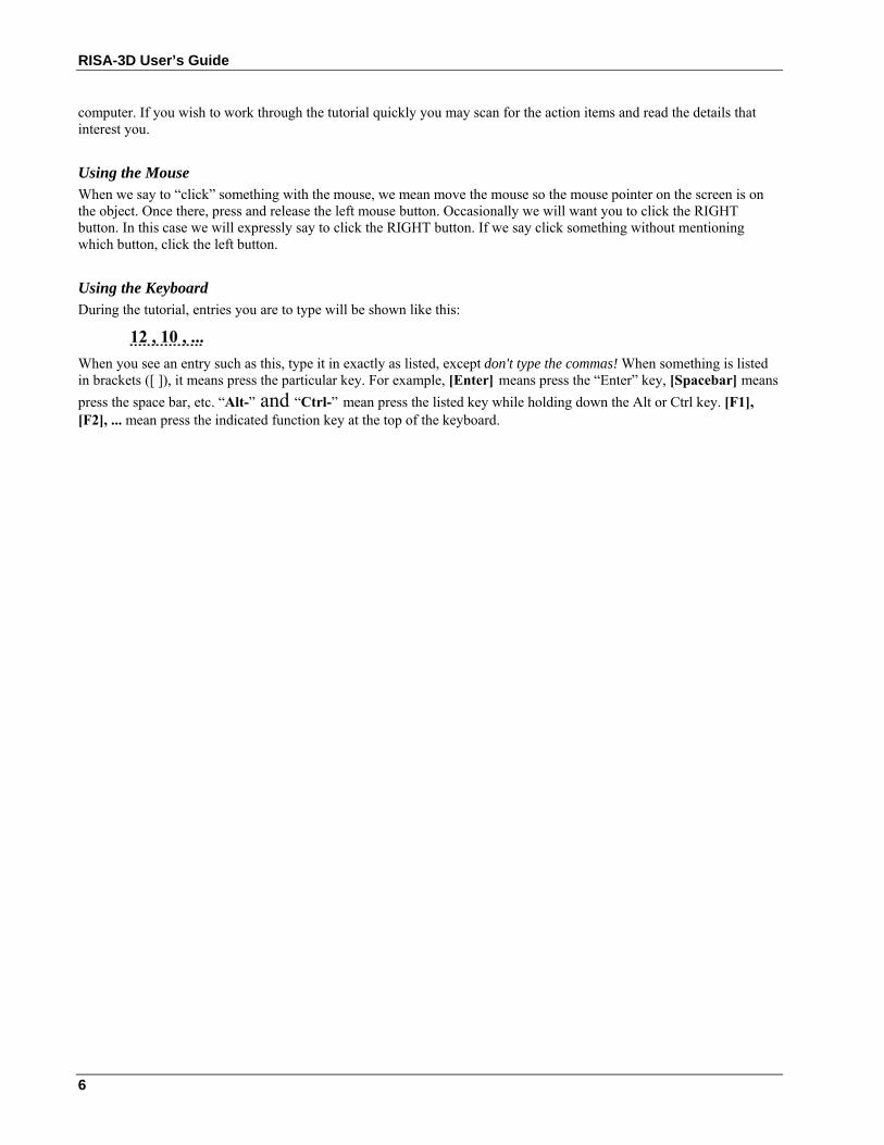
Using the Keyboard During the tutorial, entries you are to type will be shown like this:
12 , 10 , ... When you see an entry such as this, type it in exactly as listed, except don't type the commas! When something is listed in brackets ([ ]), it means press the particular key. For example, [Enter] means press the “Enter” key, [Spacebar] means press the space bar, etc. “Alt-” and “Ctrl-” mean press the listed key while holding down the Alt or Ctrl key. [F1], [F2], ... mean press the indicated function key at the top of the keyboard.
First Look at RISA-3D
7
First Look at RISA-3D
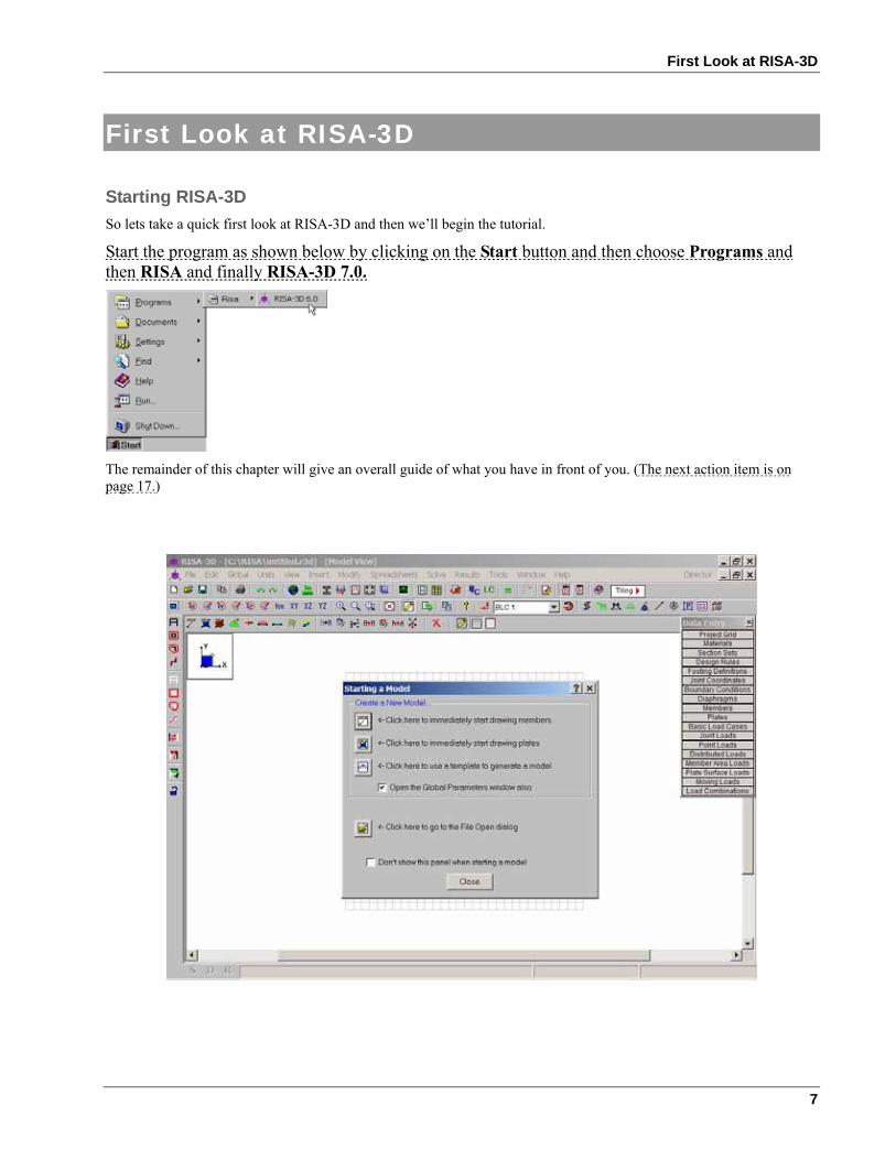
Starting RISA-3D So lets take a quick first look at RISA-3D and then we’ll begin the tutorial.
Start the program as shown below by clicking on the Start button and then choose Programs and then RISA and finally RISA-3D 7.0.
The remainder of this chapter will give an overall guide of what you have in front of you. (The next action item is on page 17.)
RISA-3D User’s Guide
8
The RISA-3D logo image in the center of the screen will disappear after a few seconds. Let’s take a moment to explain what you have in front of you.
Title Bar
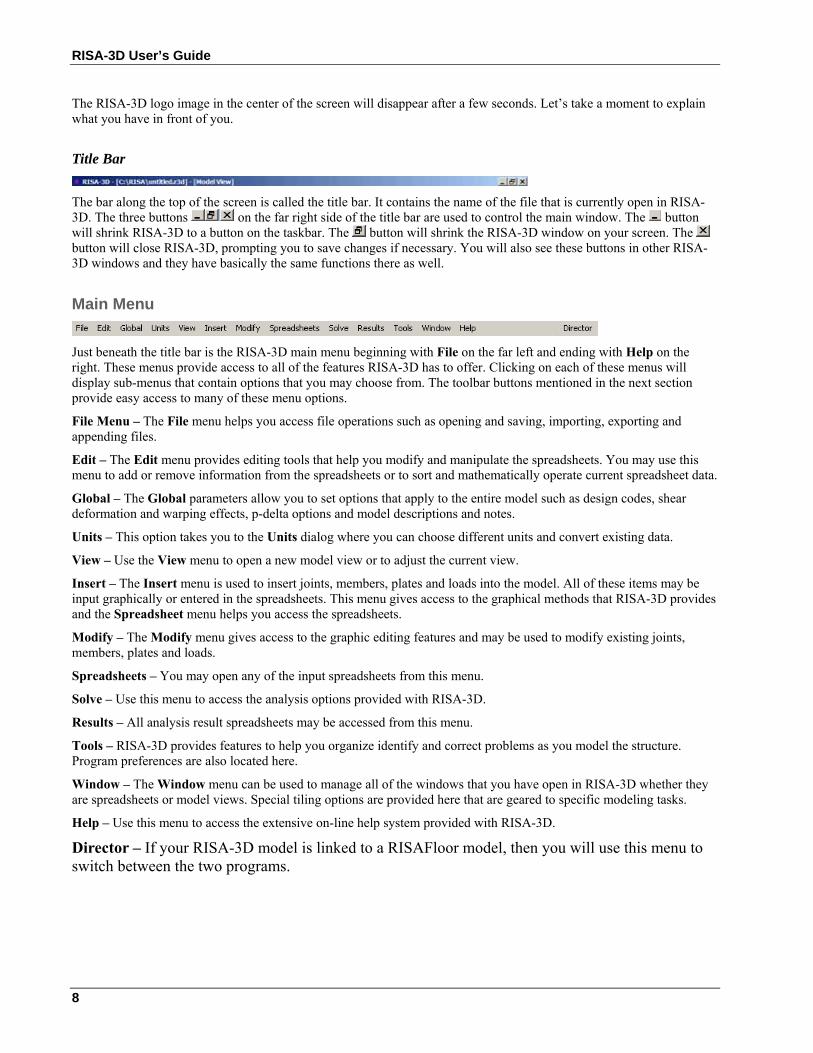
The bar along the top of the screen is called the title bar. It contains the name of the file that is currently open in RISA-3D. The three buttons on the far right side of the title bar are used to control the main window. The button will shrink RISA-3D to a button on the taskbar. The button will shrink the RISA-3D window on your screen. The button will close RISA-3D, prompting you to save changes if necessary. You will also see these buttons in other RISA-3D windows and they have basically the same functions there as well.
Main Menu
Just beneath the title bar is the RISA-3D main menu beginning with File on the far left and ending with Help on the right. These menus provide access to all of the features RISA-3D has to offer. Clicking on each of these menus will display sub-menus that contain options that you may choose from. The toolbar buttons mentioned in the next section provide easy access to many of these menu options.
File Menu – The File menu helps you access file operations such as opening and saving, importing, exporting and appending files.
Edit – The Edit menu provides editing tools that help you modify and manipulate the spreadsheets. You may use this menu to add or remove information from the spreadsheets or to sort and mathematically operate current spreadsheet data.
Global – The Global parameters allow you to set options that apply to the entire model such as design codes, shear deformation and warping effects, p-delta options and model descriptions and notes.
Units – This option takes you to the Units dialog where you can choose different units and convert existing data.
View – Use the View menu to open a new model view or to adjust the current view.
Insert – The Insert menu is used to insert joints, members, plates and loads into the model. All of these items may be input graphically or entered in the spreadsheets. This menu gives access to the graphical methods that RISA-3D provides and the Spreadsheet menu helps you access the spreadsheets.
Modify – The Modify menu gives access to the graphic editing features and may be used to modify existing joints, members, plates and loads.
Spreadsheets – You may open any of the input spreadsheets from this menu.
Solve – Use this menu to access the analysis options provided with RISA-3D.
Results – All analysis result spreadsheets may be accessed from this menu.
Tools – RISA-3D provides features to help you organize identify and correct problems as you model the structure. Program preferences are also located here.
Window – The Window menu can be used to manage all of the windows that you have open in RISA-3D whether they are spreadsheets or model views. Special tiling options are provided here that are geared to specific modeling tasks.
Help – Use this menu to access the extensive on-line help system provided with RISA-3D.
Director – If your RISA-3D model is linked to a RISAFloor model, then you will use this menu to switch between the two programs.
First Look at RISA-3D
9
Toolbars RISA-3D has toolbars with buttons to help you access common commands and popular options. All you need to note at this time is where the toolbar is. If at any time you are not sure what a particular button does, simply let your mouse hover over the button and a helpful tip will pop up and explain the button.
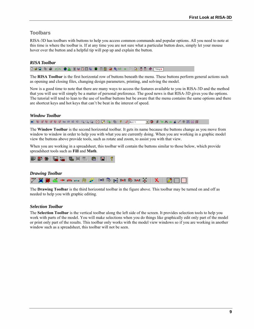
RISA Toolbar
The RISA Toolbar is the first horizontal row of buttons beneath the menu. These buttons perform general actions such as opening and closing files, changing design parameters, printing, and solving the model.
Now is a good time to note that there are many ways to access the features available to you in RISA-3D and the method that you will use will simply be a matter of personal preference. The good news is that RISA-3D gives you the options. The tutorial will tend to lean to the use of toolbar buttons but be aware that the menu contains the same options and there are shortcut keys and hot keys that can’t be beat in the interest of speed.
Window Toolbar
The Window Toolbar is the second horizontal toolbar. It gets its name because the buttons change as you move from window to window in order to help you with what you are currently doing. When you are working in a graphic model view the buttons above provide tools, such as rotate and zoom, to assist you with that view.
When you are working in a spreadsheet, this toolbar will contain the buttons similar to those below, which provide spreadsheet tools such as Fill and Math.
Drawing Toolbar
The Drawing Toolbar is the third horizontal toolbar in the figure above. This toolbar may be turned on and off as needed to help you with graphic editing.
Selection Toolbar The Selection Toolbar is the vertical toolbar along the left side of the screen. It provides selection tools to help you work with parts of the model. You will make selections when you do things like graphically edit only part of the model or print only part of the results. This toolbar only works with the model view windows so if you are working in another window such as a spreadsheet, this toolbar will not be seen.
RISA-3D User’s Guide
10
Spreadsheet Toolbars The vertical toolbar on the right of your screen is the Data Entry Toolbar. It looks a bit different because it has larger buttons with text on them, instead of pictures. This toolbar is to assist you in accessing the spreadsheets while building a model. The buttons are generally in the order in which you would typically build a model. We will use this toolbar frequently as we work through the tutorial.
A similar Results Toolbar is presented after the model has been solved to help you access the result spreadsheets.
These toolbars may be turned on and off by clicking and on the RISA Toolbar.
Workspace The actual work that you do in RISA-3D will be in the main area on the screen, which we will call the workspace. Currently the workspace contains a white model view with the default drawing grid and the New Model options. (We will see how to change the default grid and many other defaults as we go along.) As we open new model views and spreadsheets they will also appear in the workspace. This brings us to the types or windows that we can work with.
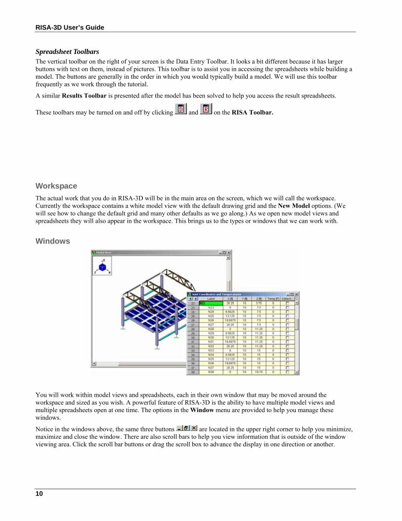
Windows
You will work within model views and spreadsheets, each in their own window that may be moved around the workspace and sized as you wish. A powerful feature of RISA-3D is the ability to have multiple model views and multiple spreadsheets open at one time. The options in the Window menu are provided to help you manage these windows.
Notice in the windows above, the same three buttons are located in the upper right corner to help you minimize, maximize and close the window. There are also scroll bars to help you view information that is outside of the window viewing area. Click the scroll bar buttons or drag the scroll box to advance the display in one direction or another.
First Look at RISA-3D
11
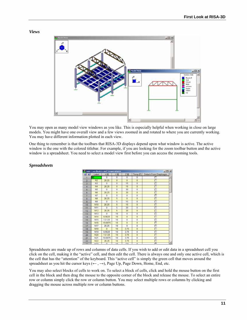
Views
You may open as many model view windows as you like. This is especially helpful when working in close on large models. You might have one overall view and a few views zoomed in and rotated to where you are currently working. You may have different information plotted in each view.
One thing to remember is that the toolbars that RISA-3D displays depend upon what window is active. The active window is the one with the colored titlebar. For example, if you are looking for the zoom toolbar button and the active window is a spreadsheet. You need to select a model view first before you can access the zooming tools.
Spreadsheets
Spreadsheets are made up of rows and columns of data cells. If you wish to add or edit data in a spreadsheet cell you click on the cell, making it the “active” cell, and then edit the cell. There is always one and only one active cell, which is the cell that has the “attention” of the keyboard. This “active cell” is simply the green cell that moves around the spreadsheet as you hit the cursor keys (← , →), Page Up, Page Down, Home, End, etc.
You may also select blocks of cells to work on. To select a block of cells, click and hold the mouse button on the first cell in the block and then drag the mouse to the opposite corner of the block and release the mouse. To select an entire row or column simply click the row or column button. You may select multiple rows or columns by clicking and dragging the mouse across multiple row or column buttons.
RISA-3D User’s Guide
12
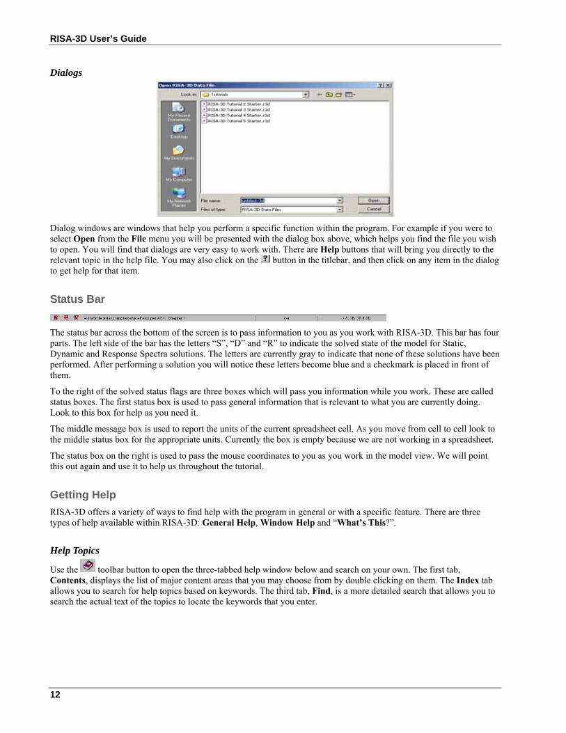
Dialogs
Dialog windows are windows that help you perform a specific function within the program. For example if you were to select Open from the File menu you will be presented with the dialog box above, which helps you find the file you wish to open. You will find that dialogs are very easy to work with. There are Help buttons that will bring you directly to the relevant topic in the help file. You may also click on the button in the titlebar, and then click on any item in the dialog to get help for that item.
Status Bar
The status bar across the bottom of the screen is to pass information to you as you work with RISA-3D. This bar has four parts. The left side of the bar has the letters “S”, “D” and “R” to indicate the solved state of the model for Static, Dynamic and Response Spectra solutions. The letters are currently gray to indicate that none of these solutions have been performed. After performing a solution you will notice these letters become blue and a checkmark is placed in front of them.
To the right of the solved status flags are three boxes which will pass you information while you work. These are called status boxes. The first status box is used to pass general information that is relevant to what you are currently doing. Look to this box for help as you need it.
The middle message box is used to report the units of the current spreadsheet cell. As you move from cell to cell look to the middle status box for the appropriate units. Currently the box is empty because we are not working in a spreadsheet.
The status box on the right is used to pass the mouse coordinates to you as you work in the model view. We will point this out again and use it to help us throughout the tutorial.
Getting Help RISA-3D offers a variety of ways to find help with the program in general or with a specific feature. There are three types of help available within RISA-3D: General Help, Window Help and “What’s This?”.
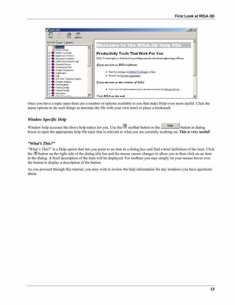
Help Topics
Use the toolbar button to open the three-tabbed help window below and search on your own. The first tab, Contents, displays the list of major content areas that you may choose from by double clicking on them. The Index tab allows you to search for help topics based on keywords. The third tab, Find, is a more detailed search that allows you to search the actual text of the topics to locate the keywords that you enter.
First Look at RISA-3D
13
Once you have a topic open there are a number of options available to you that make Help even more useful. Click the menu options to do such things as annotate the file with your own notes or place a bookmark.
Window Specific Help
Window help accesses the above help topics for you. Use the toolbar button or the button in dialog boxes to open the appropriate help file topic that is relevant to what you are currently working on. This is very useful!
“What’s This?” “What’s This?” is a Help option that lets you point to an item in a dialog box and find a brief definition of the item. Click the button on the right side of the dialog title bar and the mouse cursor changes to allow you to then click on an item in the dialog. A brief description of the item will be displayed. For toolbars you may simply let your mouse hover over the button to display a description of the button.
As you proceed through this tutorial, you may wish to review the help information for any windows you have questions about.
RISA-3D User’s Guide
14
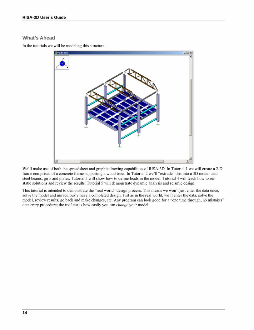
What’s Ahead In the tutorials we will be modeling this structure:
We’ll make use of both the spreadsheet and graphic drawing capabilities of RISA-3D. In Tutorial 1 we will create a 2-D frame comprised of a concrete frame supporting a wood truss. In Tutorial 2 we’ll “extrude” this into a 3D model, add steel beams, girts and plates. Tutorial 3 will show how to define loads in the model. Tutorial 4 will teach how to run static solutions and review the results. Tutorial 5 will demonstrate dynamic analysis and seismic design.
This tutorial is intended to demonstrate the “real world” design process. This means we won’t just enter the data once, solve the model and miraculously have a completed design. Just as in the real world, we’ll enter the data, solve the model, review results, go back and make changes, etc. Any program can look good for a “one time through, no mistakes” data entry procedure; the real test is how easily you can change your model!
Tutorial 1 – Modeling
15
Tutorial 1 – Modeling
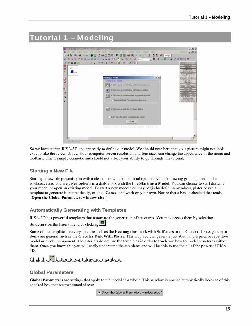
So we have started RISA-3D and are ready to define our model. We should note here that your picture might not look exactly like the screen above. Your computer screen resolution and font sizes can change the appearance of the menu and toolbars. This is simply cosmetic and should not affect your ability to go through this tutorial.
Starting a New File Starting a new file presents you with a clean slate with some initial options. A blank drawing grid is placed in the workspace and you are given options in a dialog box with the title Starting a Model. You can choose to start drawing your model or open an existing model. To start a new model you may begin by defining members, plates or use a template to generate it automatically, or click Cancel and work on your own. Notice that a box is checked that reads “Open the Global Parameters window also”.
Automatically Generating with Templates RISA-3D has powerful templates that automate the generation of structures. You may access them by selecting Structure on the Insert menu or clicking .
Some of the templates are very specific such as the Rectangular Tank with Stiffeners or the General Truss generator. Some are general such as the Circular Disk With Plates. This way you can generate just about any typical or repetitive model or model component. The tutorials do not use the templates in order to teach you how to model structures without them. Once you know this you will easily understand the templates and will be able to use the all of the power of RISA-3D.
Click the button to start drawing members.
Global Parameters Global Parameters are settings that apply to the model as a whole. This window is opened automatically because of this checked box that we mentioned above:
RISA-3D User’s Guide
16
Use your mouse to select the Description tab and click in the first field, labeled Model Title so that a flashing cursor appears there. Now type:
Tutorial Problem, [TAB]
(Type your company name) [TAB]
(Type your name) Any notes that you would like to keep with the model may be typed in the Notes area.
Notice that you hit the TAB key to move from field to field. The mouse may also be used to go directly to a field. Just put the mouse pointer on the desired field and click.
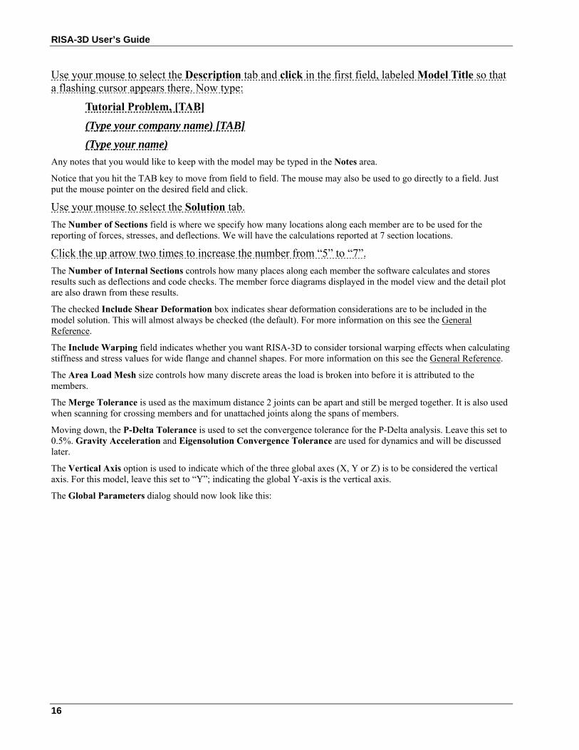
Use your mouse to select the Solution tab. The Number of Sections field is where we specify how many locations along each member are to be used for the reporting of forces, stresses, and deflections. We will have the calculations reported at 7 section locations.
Click the up arrow two times to increase the number from “5” to “7”. The Number of Internal Sections controls how many places along each member the software calculates and stores results such as deflections and code checks. The member force diagrams displayed in the model view and the detail plot are also drawn from these results.
The checked Include Shear Deformation box indicates shear deformation considerations are to be included in the model solution. This will almost always be checked (the default). For more information on this see the General Reference.
The Include Warping field indicates whether you want RISA-3D to consider torsional warping effects when calculating stiffness and stress values for wide flange and channel shapes. For more information on this see the General Reference.
The Area Load Mesh size controls how many discrete areas the load is broken into before it is attributed to the members.
The Merge Tolerance is used as the maximum distance 2 joints can be apart and still be merged together. It is also used when scanning for crossing members and for unattached joints along the spans of members.
Moving down, the P-Delta Tolerance is used to set the convergence tolerance for the P-Delta analysis. Leave this set to 0.5%. Gravity Acceleration and Eigensolution Convergence Tolerance are used for dynamics and will be discussed later.
The Vertical Axis option is used to indicate which of the three global axes (X, Y or Z) is to be considered the vertical axis. For this model, leave this set to “Y”; indicating the global Y-axis is the vertical axis.
The Global Parameters dialog should now look like this:
Tutorial 1 – Modeling
17
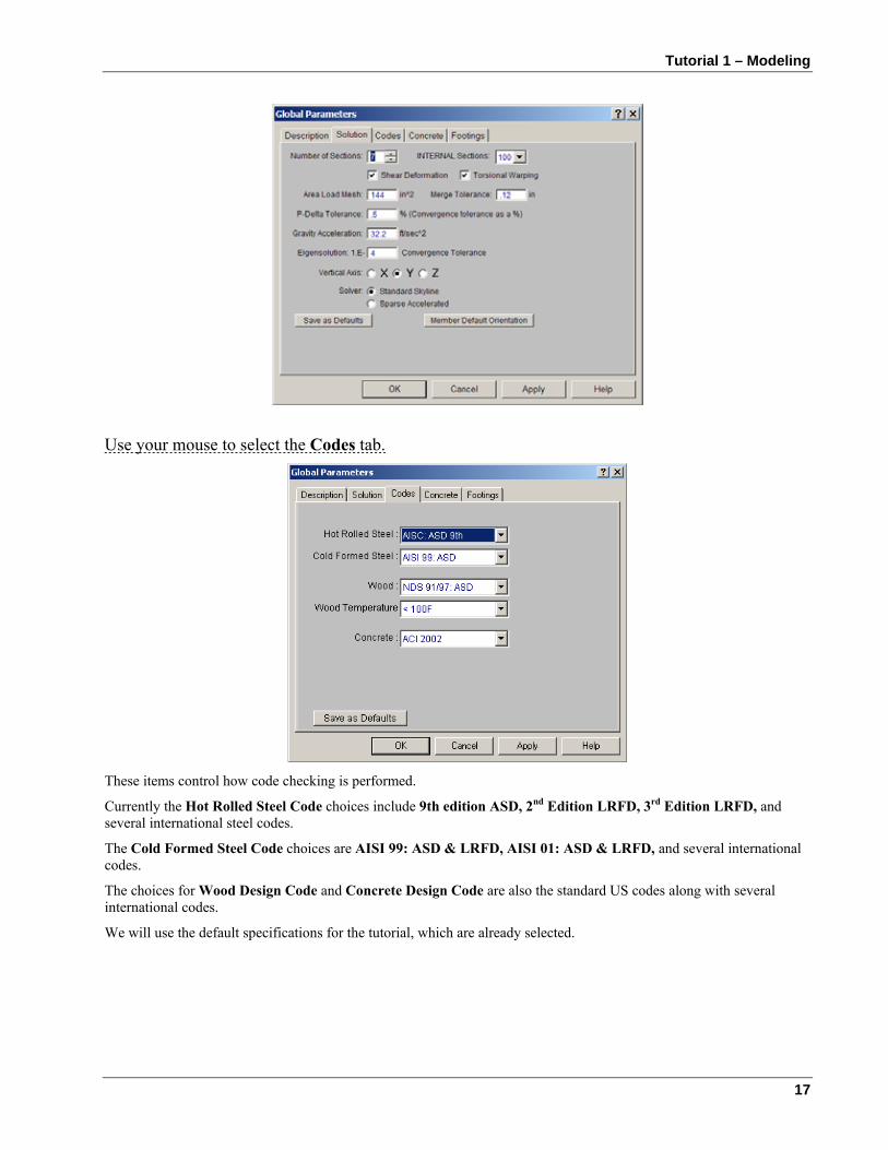
Use your mouse to select the Codes tab.
These items control how code checking is performed.
Currently the Hot Rolled Steel Code choices include 9th edition ASD, 2nd Edition LRFD, 3rd Edition LRFD, and several international steel codes.
The Cold Formed Steel Code choices are AISI 99: ASD & LRFD, AISI 01: ASD & LRFD, and several international codes.
The choices for Wood Design Code and Concrete Design Code are also the standard US codes along with several international codes.
We will use the default specifications for the tutorial, which are already selected.
RISA-3D User’s Guide
18
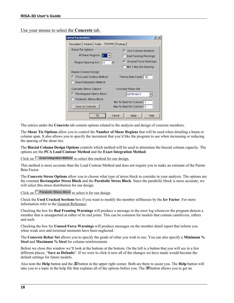
Use your mouse to select the Concrete tab.
The entries under the Concrete tab contain options related to the analysis and design of concrete members.
The Shear Tie Options allow you to control the Number of Shear Regions that will be used when detailing a beam or column span. It also allows you to specify the increment that you’d like the program to use when increasing or reducing the spacing of the shear ties.
The Biaxial Column Design Options controls which method will be used to determine the biaxial column capacity. The options are the PCA Load Contour Method and the Exact Integration Method.
Click on to select this method for our design.
This method is more accurate than the Load Contour Method and does not require you to make an estimate of the Parme Beta Factor.
The Concrete Stress Options allow you to choose what type of stress block to consider in your analysis. The options are the constant Rectangular Stress Block and the Parabolic Stress Block. Since the parabolic block is more accurate, we will select this stress distribution for our design.
Click on to select it for our design.
Check the Used Cracked Sections box if you want to modify the member stiffnesses by the Icr Factor. For more information refer to the General Reference.
Checking the box for Bad Framing Warnings will produce a message in the error log whenever the program detects a member that is unsupported at either of its end joints. This can be common for models that contain cantilevers, rafters and such.
Checking the box for Unused Force Warnings will produce messages on the member detail report that inform you when weak axis and torsional moments have been neglected.
The Concrete Rebar Set allows you to specify the grade of rebar you wish to use. You can also specify a Minimum % Steel and Maximum % Steel for column reinforcement.
Before we close this window we’ll look at the buttons at the bottom. On the left is a button that you will see in a few different places, “Save as Defaults”. If we were to click it now all of the changes we have made would become the default settings for future models.
Also note the Help button and the button in the upper right corner. Both are there to assist you. The Help button will take you to a topic in the help file that explains all of the options before you. The button allows you to get an
Tutorial 1 – Modeling
19
explanation of any one option you click on. Click on Help to see a detailed explanation for all of the options on this window.
Note, you will also see a tab labeled Footings if you have RISAFoot installed.
Now close the Global Parameters window by clicking OK.
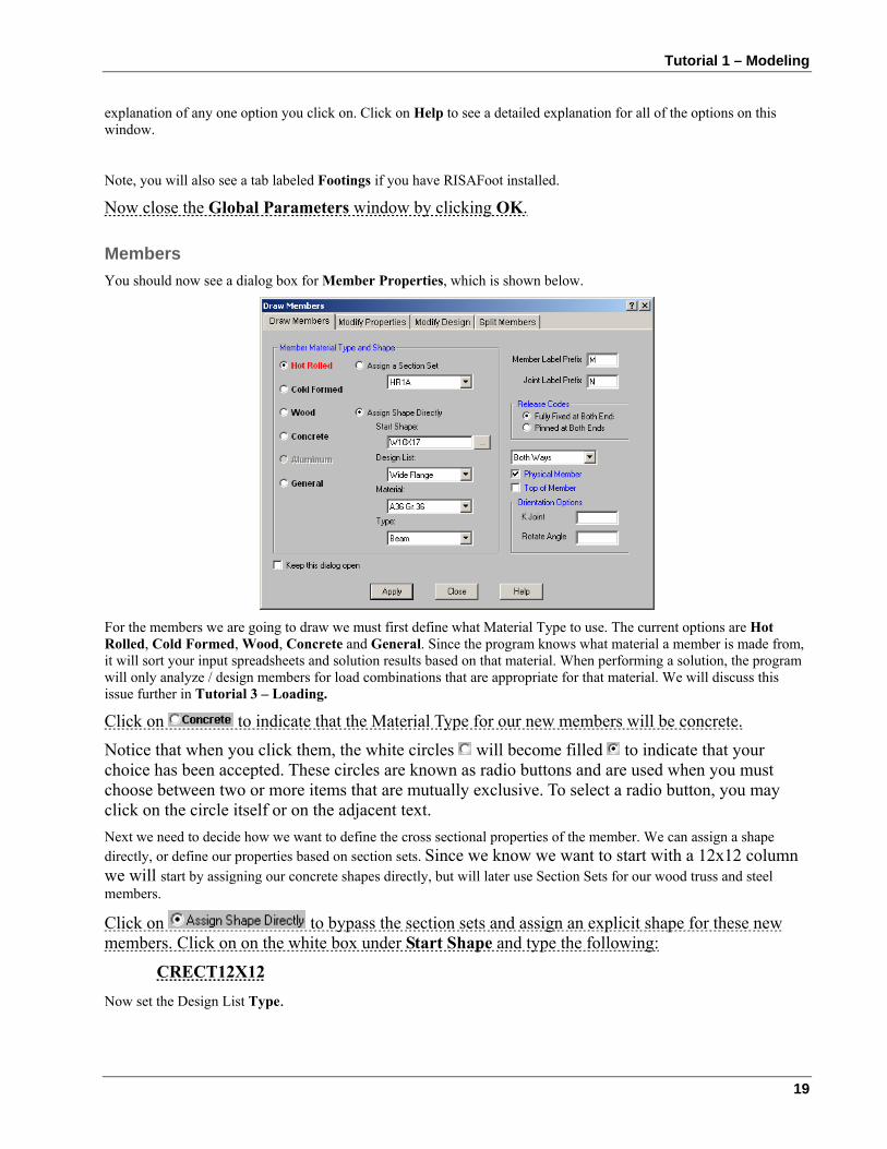
Members You should now see a dialog box for Member Properties, which is shown below.
For the members we are going to draw we must first define what Material Type to use. The current options are Hot Rolled, Cold Formed, Wood, Concrete and General. Since the program knows what material a member is made from, it will sort your input spreadsheets and solution results based on that material. When performing a solution, the program will only analyze / design members for load combinations that are appropriate for that material. We will discuss this issue further in Tutorial 3 – Loading.
Click on to indicate that the Material Type for our new members will be concrete.
Notice that when you click them, the white circles will become filled to indicate that your choice has been accepted. These circles are known as radio buttons and are used when you must choose between two or more items that are mutually exclusive. To select a radio button, you may click on the circle itself or on the adjacent text. Next we need to decide how we want to define the cross sectional properties of the member. We can assign a shape directly, or define our properties based on section sets. Since we know we want to start with a 12x12 column we will start by assigning our concrete shapes directly, but will later use Section Sets for our wood truss and steel members.
Click on to bypass the section sets and assign an explicit shape for these new members. Click on on the white box under Start Shape and type the following:
CRECT12X12 Now set the Design List Type.
RISA-3D User’s Guide
20
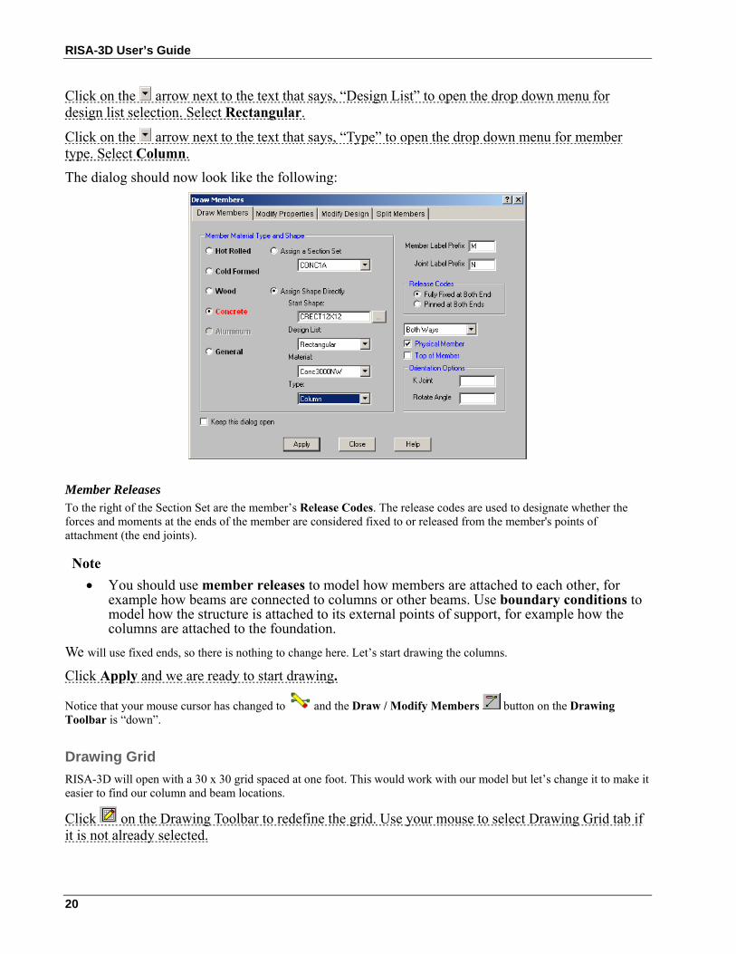
Click on the arrow next to the text that says, “Design List” to open the drop down menu for design list selection. Select Rectangular.
Click on the arrow next to the text that says, “Type” to open the drop down menu for member type. Select Column.
The dialog should now look like the following:
Member Releases To the right of the Section Set are the member’s Release Codes. The release codes are used to designate whether the forces and moments at the ends of the member are considered fixed to or released from the member's points of attachment (the end joints).
Note • You should use member releases to model how members are attached to each other, for
example how beams are connected to columns or other beams. Use boundary conditions to model how the structure is attached to its external points of support, for example how the columns are attached to the foundation.
We will use fixed ends, so there is nothing to change here. Let’s start drawing the columns.
Click Apply and we are ready to start drawing.
Notice that your mouse cursor has changed to and the Draw / Modify Members button on the Drawing Toolbar is “down”.
Drawing Grid RISA-3D will open with a 30 x 30 grid spaced at one foot. This would work with our model but let’s change it to make it easier to find our column and beam locations.
Click on the Drawing Toolbar to redefine the grid. Use your mouse to select Drawing Grid tab if it is not already selected.
Tutorial 1 – Modeling
21
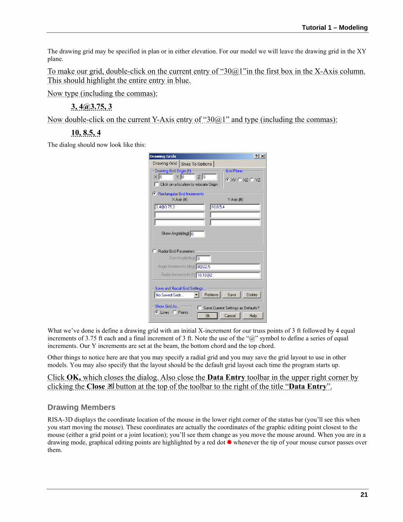
The drawing grid may be specified in plan or in either elevation. For our model we will leave the drawing grid in the XY plane.
To make our grid, double-click on the current entry of “30@1”in the first box in the X-Axis column. This should highlight the entire entry in blue.
Now type (including the commas):
3, [email protected], 3 Now double-click on the current Y-Axis entry of “30@1” and type (including the commas):
10, 8.5, 4 The dialog should now look like this:
What we’ve done is define a drawing grid with an initial X-increment for our truss points of 3 ft followed by 4 equal increments of 3.75 ft each and a final increment of 3 ft. Note the use of the “@” symbol to define a series of equal increments. Our Y increments are set at the beam, the bottom chord and the top chord.
Other things to notice here are that you may specify a radial grid and you may save the grid layout to use in other models. You may also specify that the layout should be the default grid layout each time the program starts up.
Click OK, which closes the dialog. Also close the Data Entry toolbar in the upper right corner by clicking the Close button at the top of the toolbar to the right of the title “Data Entry”.
Drawing Members RISA-3D displays the coordinate location of the mouse in the lower right corner of the status bar (you’ll see this when you start moving the mouse). These coordinates are actually the coordinates of the graphic editing point closest to the mouse (either a grid point or a joint location); you’ll see them change as you move the mouse around. When you are in a drawing mode, graphical editing points are highlighted by a red dot whenever the tip of your mouse cursor passes over them.
RISA-3D User’s Guide
22
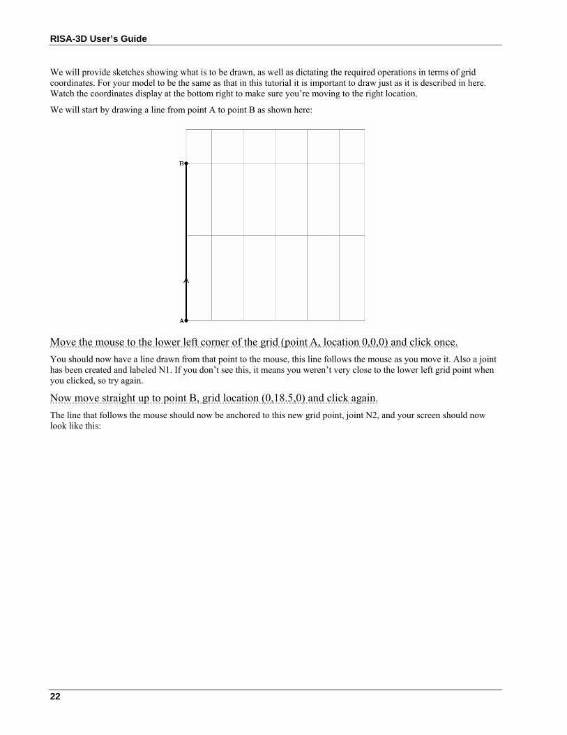
We will provide sketches showing what is to be drawn, as well as dictating the required operations in terms of grid coordinates. For your model to be the same as that in this tutorial it is important to draw just as it is described in here. Watch the coordinates display at the bottom right to make sure you’re moving to the right location.
We will start by drawing a line from point A to point B as shown here:
Move the mouse to the lower left corner of the grid (point A, location 0,0,0) and click once. You should now have a line drawn from that point to the mouse, this line follows the mouse as you move it. Also a joint has been created and labeled N1. If you don’t see this, it means you weren’t very close to the lower left grid point when you clicked, so try again.
Now move straight up to point B, grid location (0,18.5,0) and click again. The line that follows the mouse should now be anchored to this new grid point, joint N2, and your screen should now look like this:
Tutorial 1 – Modeling
23
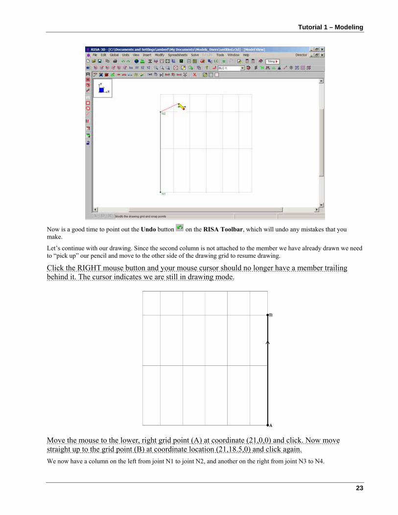
Now is a good time to point out the Undo button on the RISA Toolbar, which will undo any mistakes that you make.
Let’s continue with our drawing. Since the second column is not attached to the member we have already drawn we need to “pick up” our pencil and move to the other side of the drawing grid to resume drawing.
Click the RIGHT mouse button and your mouse cursor should no longer have a member trailing behind it. The cursor indicates we are still in drawing mode.
Move the mouse to the lower, right grid point (A) at coordinate (21,0,0) and click. Now move straight up to the grid point (B) at coordinate location (21,18.5,0) and click again. We now have a column on the left from joint N1 to joint N2, and another on the right from joint N3 to N4.
RISA-3D User’s Guide
24
Click the right mouse button to “pick-up” the pencil. Click the right mouse button again to stop drawing.
This will pop the button back “up” and the cursor becomes the standard arrow .
Before drawing the truss we will change the way that members are shown and make them color-coded by their section sets.
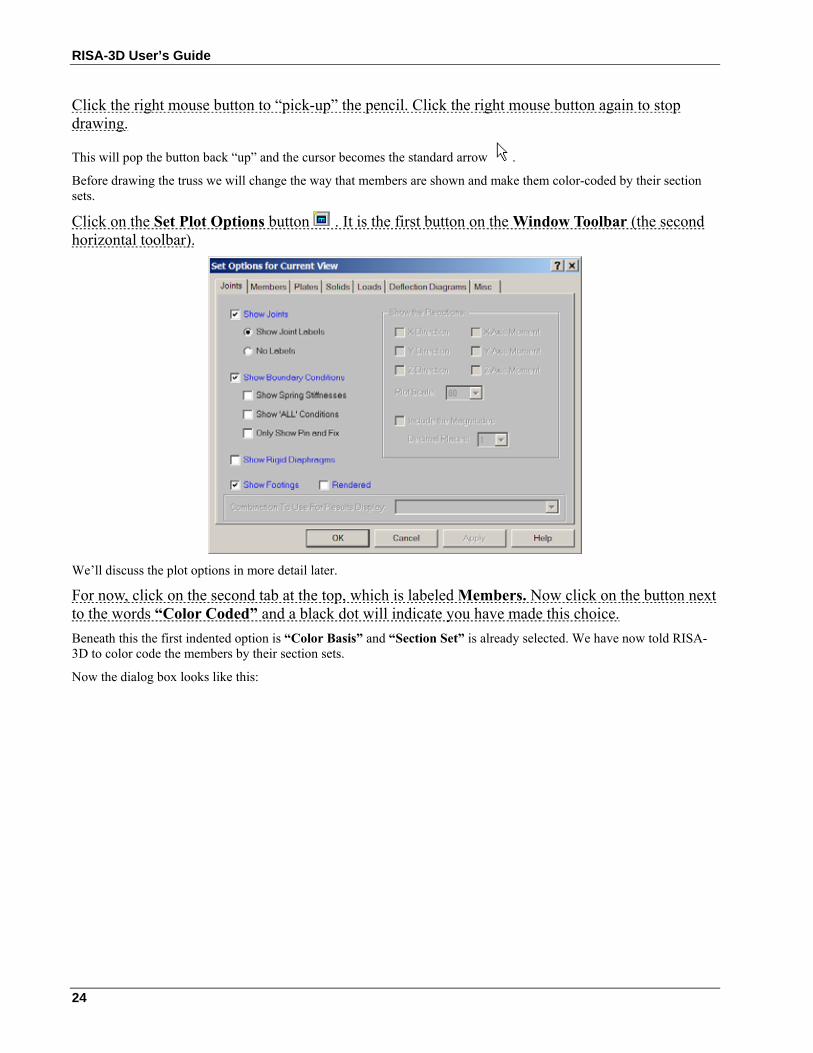
Click on the Set Plot Options button . It is the first button on the Window Toolbar (the second horizontal toolbar).
We’ll discuss the plot options in more detail later.
For now, click on the second tab at the top, which is labeled Members. Now click on the button next to the words “Color Coded” and a black dot will indicate you have made this choice. Beneath this the first indented option is “Color Basis” and “Section Set” is already selected. We have now told RISA-3D to color code the members by their section sets.
Now the dialog box looks like this:
Tutorial 1 – Modeling
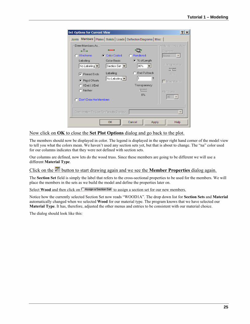
25
Now click on OK to close the Set Plot Options dialog and go back to the plot. The members should now be displayed in color. The legend is displayed in the upper right hand corner of the model view to tell you what the colors mean. We haven’t used any section sets yet, but that is about to change. The “na” color used for our columns indicates that they were not defined with section sets.
Our columns are defined, now lets do the wood truss. Since these members are going to be different we will use a different Material Type.
Click on the button to start drawing again and we see the Member Properties dialog again. The Section Set field is simply the label that refers to the cross-sectional properties to be used for the members. We will place the members in the sets as we build the model and define the properties later on.
Select Wood and then click on to assign a section set for our new members.
Notice how the currently selected Section Set now reads “WOOD1A”. The drop down list for Section Sets and Material automatically changed when we selected Wood for our material type. The program knows that we have selected our Material Type. It has, therefore, adjusted the other menus and entries to be consistent with our material choice.
The dialog should look like this:
RISA-3D User’s Guide
26
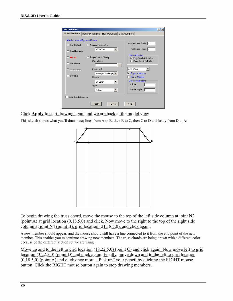
Click Apply to start drawing again and we are back at the model view. This sketch shows what you’ll draw next; lines from A to B, then B to C, then C to D and lastly from D to A:
To begin drawing the truss chord, move the mouse to the top of the left side column at joint N2 (point A) at grid location (0,18.5,0) and click. Now move to the right to the top of the right side column at joint N4 (point B), grid location (21,18.5,0), and click again. A new member should appear, and the mouse should still have a line connected to it from the end point of the new member. This enables you to continue drawing new members. The truss chords are being drawn with a different color because of the different section set we are using.
Move up and to the left to grid location (18,22.5,0) (point C) and click again. Now move left to grid location (3,22.5,0) (point D) and click again. Finally, move down and to the left to grid location (0,18.5,0) (point A) and click once more. “Pick up” your pencil by clicking the RIGHT mouse button. Click the RIGHT mouse button again to stop drawing members.
Tutorial 1 – Modeling
27
The truss chord members are now defined. Next we’ll draw the web members. We will use the WOOD1A section set again, but will later change this assignment to give the web members different properties from the truss chords.
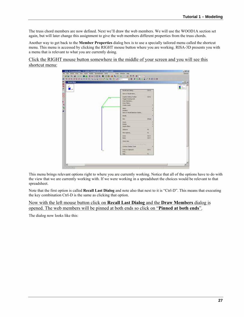
Another way to get back to the Member Properties dialog box is to use a specially tailored menu called the shortcut menu. This menu is accessed by clicking the RIGHT mouse button where you are working. RISA-3D presents you with a menu that is relevant to what you are currently doing.
Click the RIGHT mouse button somewhere in the middle of your screen and you will see this shortcut menu:
This menu brings relevant options right to where you are currently working. Notice that all of the options have to do with the view that we are currently working with. If we were working in a spreadsheet the choices would be relevant to that spreadsheet.
Note that the first option is called Recall Last Dialog and note also that next to it is “Ctrl-D”. This means that executing the key combination Ctrl-D is the same as clicking that option.
Now with the left mouse button click on Recall Last Dialog and the Draw Members dialog is opened. The web members will be pinned at both ends so click on “Pinned at both ends”. The dialog now looks like this:
RISA-3D User’s Guide
28
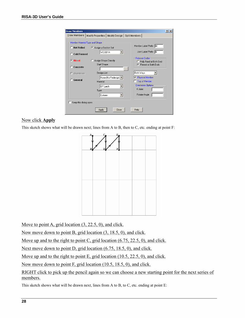
Now click Apply This sketch shows what will be drawn next; lines from A to B, then to C, etc. ending at point F:
Move to point A, grid location (3, 22.5, 0), and click.
Now move down to point B, grid location (3, 18.5, 0), and click.
Move up and to the right to point C, grid location (6.75, 22.5, 0), and click.
Next move down to point D, grid location (6.75, 18.5, 0), and click.
Move up and to the right to point E, grid location (10.5, 22.5, 0), and click.
Now move down to point F, grid location (10.5, 18.5, 0), and click.
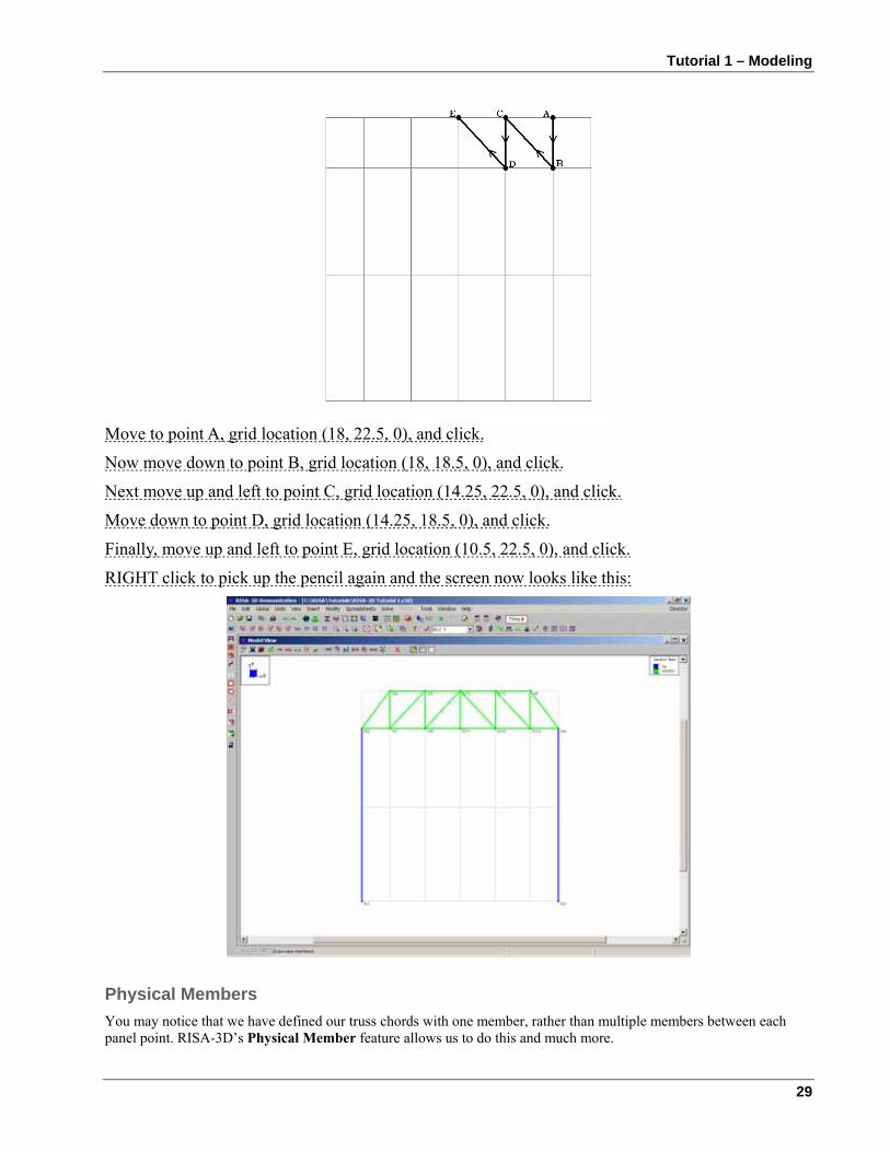
RIGHT click to pick up the pencil again so we can choose a new starting point for the next series of members. This sketch shows what will be drawn next, lines from A to B, to C, etc. ending at point E:
Tutorial 1 – Modeling
29
Move to point A, grid location (18, 22.5, 0), and click.
Now move down to point B, grid location (18, 18.5, 0), and click.
Next move up and left to point C, grid location (14.25, 22.5, 0), and click.
Move down to point D, grid location (14.25, 18.5, 0), and click.
Finally, move up and left to point E, grid location (10.5, 22.5, 0), and click.
RIGHT click to pick up the pencil again and the screen now looks like this:
Physical Members You may notice that we have defined our truss chords with one member, rather than multiple members between each panel point. RISA-3D’s Physical Member feature allows us to do this and much more.
RISA-3D User’s Guide
30
Physical Members automatically connect the members that frame into them. This means that you don’t have to use multiple members to model what is one Physical Member in the field. Later when changes are made to the model you don’t have to work with multiple smaller members to make modifications. Most important, the results for these members will not be spread out over multiple members, making it difficult to find design values. RISA-3D does all of the bookkeeping behind the scenes letting you see your model as it really is.
RISA-3D starts you off with one section set for each basic material type. We will have to create new ones as we go along. Creating new sections is accomplished in the Sections spreadsheet. While we are there we will define the section properties for all the members that we have defined thus far. We have not defined any material properties either, which will be done in the Material spreadsheet.
Click on the RISA Toolbar to bring back the Data Entry Toolbar.
Material Properties
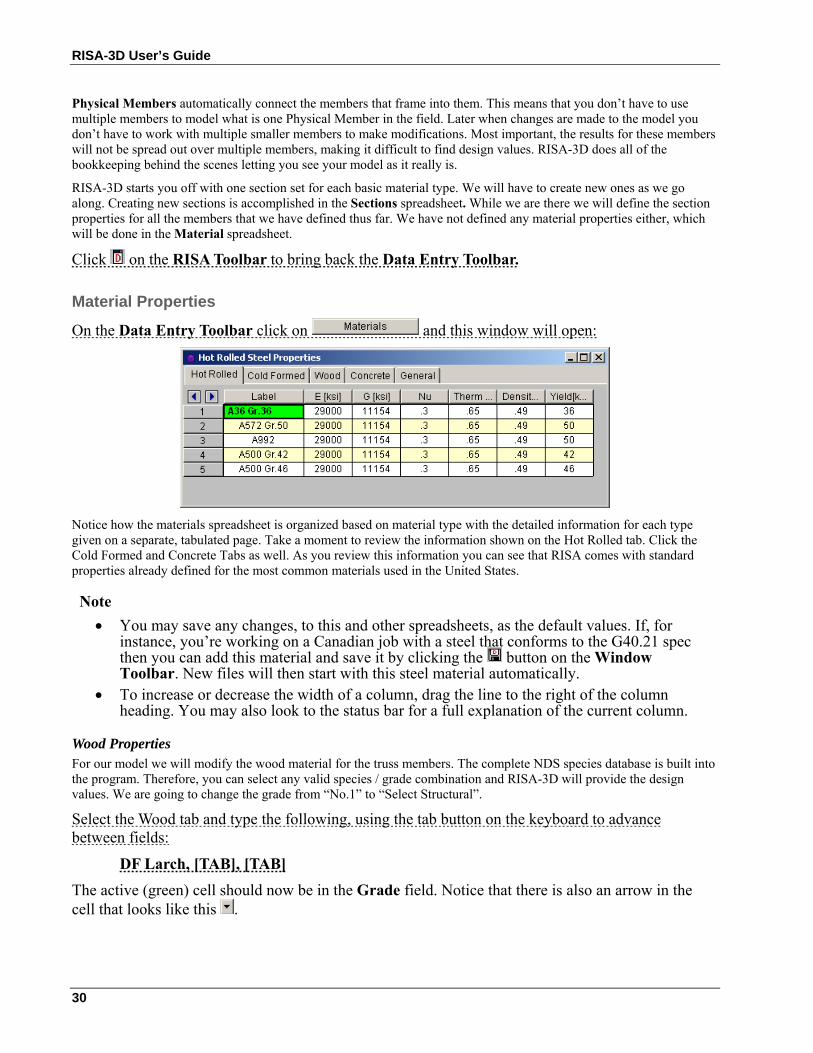
On the Data Entry Toolbar click on and this window will open:
Notice how the materials spreadsheet is organized based on material type with the detailed information for each type given on a separate, tabulated page. Take a moment to review the information shown on the Hot Rolled tab. Click the Cold Formed and Concrete Tabs as well. As you review this information you can see that RISA comes with standard properties already defined for the most common materials used in the United States.
Note • You may save any changes, to this and other spreadsheets, as the default values. If, for
instance, you’re working on a Canadian job with a steel that conforms to the G40.21 spec then you can add this material and save it by clicking the button on the Window Toolbar. New files will then start with this steel material automatically.
• To increase or decrease the width of a column, drag the line to the right of the column heading. You may also look to the status bar for a full explanation of the current column.
Wood Properties For our model we will modify the wood material for the truss members. The complete NDS species database is built into the program. Therefore, you can select any valid species / grade combination and RISA-3D will provide the design values. We are going to change the grade from “No.1” to “Select Structural”.
Select the Wood tab and type the following, using the tab button on the keyboard to advance between fields:
DF Larch, [TAB], [TAB] The active (green) cell should now be in the Grade field. Notice that there is also an arrow in the cell that looks like this .
Tutorial 1 – Modeling
31
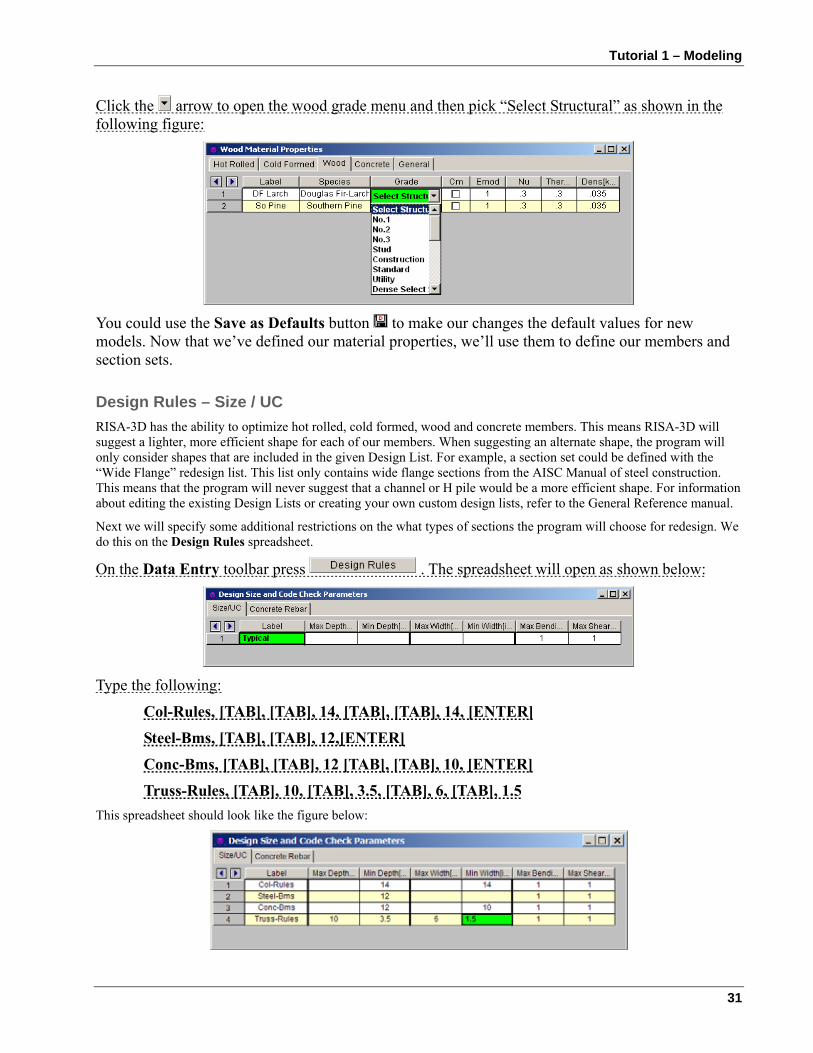
Click the arrow to open the wood grade menu and then pick “Select Structural” as shown in the following figure:
You could use the Save as Defaults button to make our changes the default values for new models. Now that we’ve defined our material properties, we’ll use them to define our members and section sets.
Design Rules – Size / UC RISA-3D has the ability to optimize hot rolled, cold formed, wood and concrete members. This means RISA-3D will suggest a lighter, more efficient shape for each of our members. When suggesting an alternate shape, the program will only consider shapes that are included in the given Design List. For example, a section set could be defined with the “Wide Flange” redesign list. This list only contains wide flange sections from the AISC Manual of steel construction. This means that the program will never suggest that a channel or H pile would be a more efficient shape. For information about editing the existing Design Lists or creating your own custom design lists, refer to the General Reference manual.
Next we will specify some additional restrictions on the what types of sections the program will choose for redesign. We do this on the Design Rules spreadsheet.
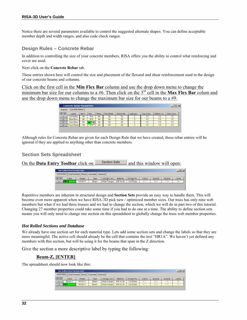
On the Data Entry toolbar press . The spreadsheet will open as shown below:
Type the following:
Col-Rules, [TAB], [TAB], 14, [TAB], [TAB], 14, [ENTER]
Steel-Bms, [TAB], [TAB], 12,[ENTER]
Conc-Bms, [TAB], [TAB], 12 [TAB], [TAB], 10, [ENTER]
Truss-Rules, [TAB], 10, [TAB], 3.5, [TAB], 6, [TAB], 1.5 This spreadsheet should look like the figure below:
RISA-3D User’s Guide
32
Notice there are several parameters available to control the suggested alternate shapes. You can define acceptable member depth and width ranges, and also code check ranges.
Design Rules – Concrete Rebar In addition to controlling the size of your concrete members, RISA offers you the ability to control what reinforcing and cover are used.
Next click on the Concrete Rebar tab.
These entries shown here will control the size and placement of the flexural and shear reinforcement used in the design of our concrete beams and columns.
Click on the first cell in the Min Flex Bar column and use the drop down menu to change the minimum bar size for our columns to a #6. Then click on the 3rd cell in the Max Flex Bar colum and use the drop down menu to change the maximum bar size for our beams to a #9.
Although rules for Concrete Rebar are given for each Design Rule that we have created, these rebar entries will be ignored if they are applied to anything other than concrete members.
Section Sets Spreadsheet
On the Data Entry Toolbar click on and this window will open:
Repetitive members are inherent in structural design and Section Sets provide an easy way to handle them. This will become even more apparent when we have RISA-3D pick new / optimized member sizes. Our truss has only nine web members but what if we had three trusses and we had to change the section, which we will do in part two of this tutorial. Changing 27 member properties could take some time if you had to do one at a time. The ability to define section sets means you will only need to change one section on this spreadsheet to globally change the truss web member properties.
Hot Rolled Sections and Database We already have one section set for each material type. Lets add some section sets and change the labels so that they are more meaningful. The active cell should already be the cell that contains the text “HR1A”. We haven’t yet defined any members with this section, but will be using it for the beams that span in the Z direction.
Give the section a more descriptive label by typing the following:
Beam-Z, [ENTER] The spreadsheet should now look like this:
Tutorial 1 – Modeling
33
Note that pressing ENTER has also created a new line, which we do not need for our model. This will allow us to demonstrate how to delete a line.
Remember that the Window Toolbar will change as you move from window to window so that the buttons are relevant to what you are currently doing. It now looks like this:
Click the second button , which deletes the current line.
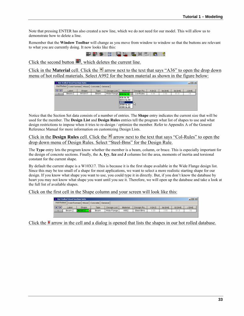
Click in the Material cell. Click the arrow next to the text that says “A36” to open the drop down menu of hot rolled materials. Select A992 for the beam material as shown in the figure below:
Notice that the Section Set data consists of a number of entries. The Shape entry indicates the current size that will be used for the member. The Design List and Design Rules entries tell the program what list of shapes to use and what design restrictions to impose when it tries to re-design / optimize the member. Refer to Appendix A of the General Reference Manual for more information on customizing Design Lists.
Click in the Design Rules cell. Click the arrow next to the text that says “Col-Rules” to open the drop down menu of Design Rules. Select “Steel-Bms” for the Design Rule. The Type entry lets the program know whether the member is a beam, column, or brace. This is especially important for the design of concrete sections. Finally, the A, Iyy, Izz and J columns list the area, moments of inertia and torsional constant for the current shape.
By default the current shape is a W10X17. This is because it is the first shape available in the Wide Flange design list. Since this may be too small of a shape for most applications, we want to select a more realistic starting shape for our design. If you know what shape you want to use, you could type it in directly. But, if you don’t know the database by heart you may not know what shape you want until you see it. Therefore, we will open up the database and take a look at the full list of available shapes.
Click on the first cell in the Shape column and your screen will look like this:
Click the arrow in the cell and a dialog is opened that lists the shapes in our hot rolled database.
RISA-3D User’s Guide
34
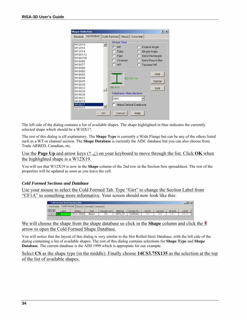
The left side of the dialog contains a list of available shapes. The shape highlighted in blue indicates the currently selected shape which should be a W10X17.
The rest of this dialog is elf-explanatory. The Shape Type is currently a Wide Flange but can be any of the others listed such as a WT or channel section. The Shape Database is currently the AISC database but you can also choose from Trade ARBED, Canadian, etc.
Use the Page Up and arrow keys (↑ ,↓) on your keyboard to move through the list. Click OK when the highlighted shape is a W12X19. You will see that W12X19 is now in the Shape column of the 2nd row in the Section Sets spreadsheet. The rest of the properties will be updated as soon as you leave the cell.
Cold Formed Sections and Database Use your mouse to select the Cold Formed Tab. Type “Girt” to change the Section Label from “CF1A” to something more informative. Your screen should now look like this:
We will choose the shape from the shape database so click in the Shape column and click the arrow to open the Cold Formed Shape Database. You will notice that the layout of this dialog is very similar to the Hot Rolled Steel Database, with the left side of the dialog containing a list of available shapes. The rest of this dialog contains selections for Shape Type and Shape Database. The current database is the AISI 1999 which is appropiate for our example.
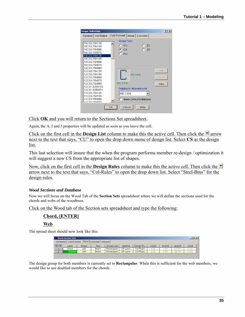
Select CS as the shape type (in the middle). Finally choose 14CS3.75X135 as the selection at the top of the list of available shapes.
Tutorial 1 – Modeling
35
Click OK and you will return to the Sections Set spreadsheet. Again, the A, I and J properties will be updated as soon as you leave the cell.
Click on the first cell in the Design List column to make this the active cell. Then click the arrow next to the text that says, “CU” to open the drop down menu of design list. Select CS as the design list.
This last selection will insure that the when the program performs member re-design / optimization it will suggest a new CS from the appropriate list of shapes.
Now, click on the first cell in the Design Rules column to make this the active cell. Then click the arrow next to the text that says, “Col-Rules” to open the drop down list. Select “Steel-Bms” for the design rules.
Wood Sections and Database Now we will focus on the Wood Tab of the Section Sets spreadsheet where we will define the sections used for the chords and webs of the woodtruss.
Click on the Wood tab of the Section sets spreadsheet and type the following:
Chord, [ENTER]
Web The spread sheet should now look like this:
The design group for both members is currently set to Rectangular. While this is sufficient for the web members, we would like to use doubled members for the chords.
RISA-3D User’s Guide
36
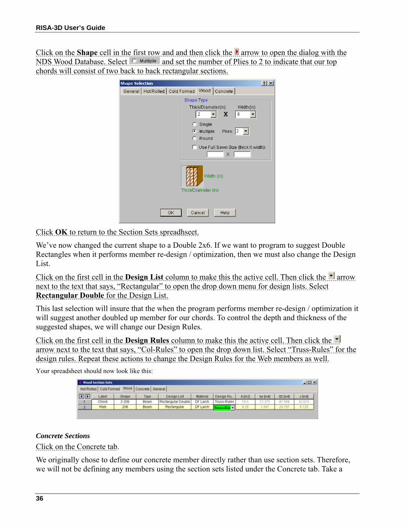
Click on the Shape cell in the first row and and then click the arrow to open the dialog with the NDS Wood Database. Select and set the number of Plies to 2 to indicate that our top chords will consist of two back to back rectangular sections.
Click OK to return to the Section Sets spreadhseet.
We’ve now changed the current shape to a Double 2x6. If we want to program to suggest Double Rectangles when it performs member re-design / optimization, then we must also change the Design List.
Click on the first cell in the Design List column to make this the active cell. Then click the arrow next to the text that says, “Rectangular” to open the drop down menu for design lists. Select Rectangular Double for the Design List.
This last selection will insure that the when the program performs member re-design / optimization it will suggest another doubled up member for our chords. To control the depth and thickness of the suggested shapes, we will change our Design Rules.
Click on the first cell in the Design Rules column to make this the active cell. Then click the arrow next to the text that says, “Col-Rules” to open the drop down list. Select “Truss-Rules” for the design rules. Repeat these actions to change the Design Rules for the Web members as well. Your spreadsheet should now look like this:
Concrete Sections Click on the Concrete tab.
We originally chose to define our concrete member directly rather than use section sets. Therefore, we will not be defining any members using the section sets listed under the Concrete tab. Take a
Tutorial 1 – Modeling
37
minute to review the information listed here. Just like with the steel and wood tabs, the information consists of a section Label, Shape, Design List, member Type, Material and Design Rules.
Multiple Windows
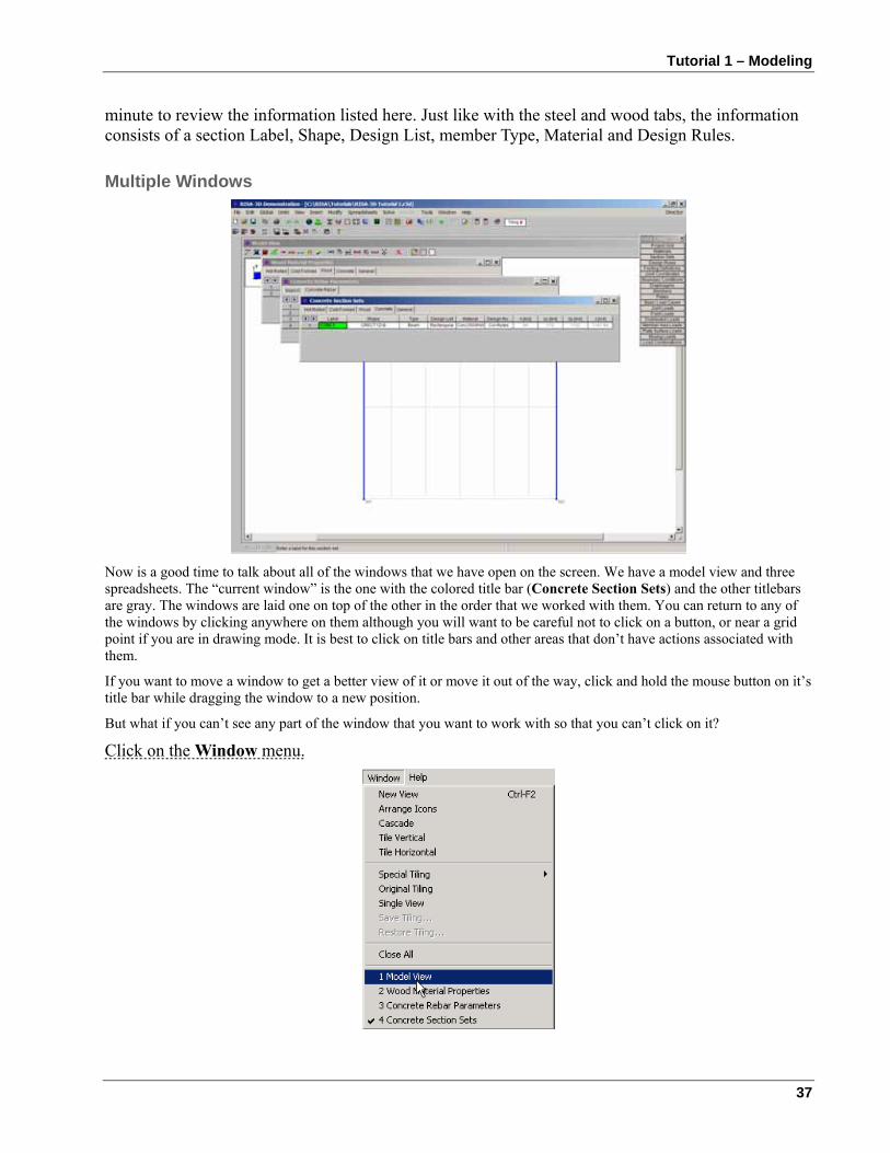
Now is a good time to talk about all of the windows that we have open on the screen. We have a model view and three spreadsheets. The “current window” is the one with the colored title bar (Concrete Section Sets) and the other titlebars are gray. The windows are laid one on top of the other in the order that we worked with them. You can return to any of the windows by clicking anywhere on them although you will want to be careful not to click on a button, or near a grid point if you are in drawing mode. It is best to click on title bars and other areas that don’t have actions associated with them.
If you want to move a window to get a better view of it or move it out of the way, click and hold the mouse button on it’s title bar while dragging the window to a new position.
But what if you can’t see any part of the window that you want to work with so that you can’t click on it?
Click on the Window menu.
RISA-3D User’s Guide
38
The top of the Window menu presents some arrangement and tiling options that we will get to later. At the bottom of the menu the open windows are listed. Notice that they are numbered in the order that we opened them starting with the Model View and ending with the Member Section Sets we just finished. The current window has a checkmark next to it. We can choose any of the open windows from this list at any time. So if you hide a window or just want to see what is already open you can always come here.
Now select the Model View by clicking on “1: Model View”. The Model View comes to the front of the workspace and the spreadsheets are no longer visible. They are still open however but are behind the larger model view window.
You can also recall open windows the same way that you originally opened them whether it was with a menu or a toolbar button.
As an example, click on the button in the Data Entry Toolbar. This window was already open and it was brought to where you can work with it.
You may close windows either by clicking the close button or by pressing the Ctrl and F4 buttons simultaneously.
Press Ctrl-F4 to close the Sections spreadsheet.
Back in the model view our cursor is still which indicates that we are still in drawing mode. RISA-3D remembers what mode you are in for all the open windows. We need to draw the crossbeam but we are still set up for drawing web members however because that is what we were doing when we left the model view.
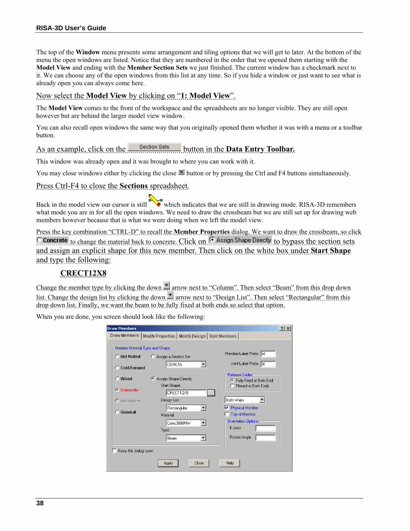
Press the key combination “CTRL-D” to recall the Member Properties dialog. We want to draw the crossbeam, so click to change the material back to concrete. Click on to bypass the section sets
and assign an explicit shape for this new member. Then click on the white box under Start Shape and type the following:
CRECT12X8
Change the member type by clicking the down arrow next to “Column”. Then select “Beam” from this drop down list. Change the design list by clicking the down arrow next to “Design List”. Then select “Rectangular” from this drop down list. Finally, we want the beam to be fully fixed at both ends so select that option.
When you are done, you screen should look like the following:
Tutorial 1 – Modeling
39
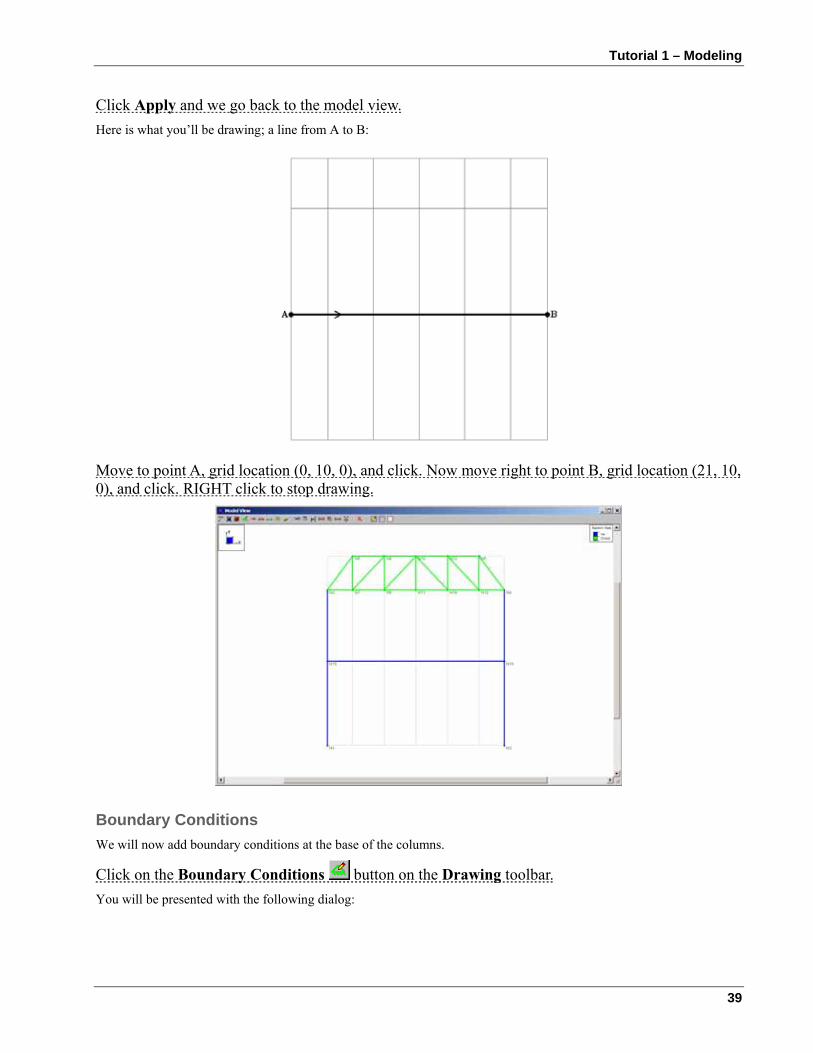
Click Apply and we go back to the model view. Here is what you’ll be drawing; a line from A to B:
Move to point A, grid location (0, 10, 0), and click. Now move right to point B, grid location (21, 10, 0), and click. RIGHT click to stop drawing.
Boundary Conditions We will now add boundary conditions at the base of the columns.
Click on the Boundary Conditions button on the Drawing toolbar. You will be presented with the following dialog:
RISA-3D User’s Guide
40
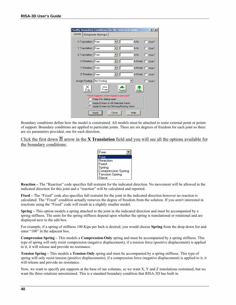
Boundary conditions define how the model is constrained. All models must be attached to some external point or points of support. Boundary conditions are applied to particular joints. There are six degrees of freedom for each joint so there are six parameters provided, one for each direction.
Click the first down arrow in the X Translation field and you will see all the options available for the boundary conditions:
Reaction – The “Reaction” code specifies full restraint for the indicated direction. No movement will be allowed in the indicated direction for this joint and a “reaction” will be calculated and reported.
Fixed – The “Fixed” code also specifies full restraint for the joint in the indicated direction however no reaction is calculated. The “Fixed” condition actually removes the degree of freedom from the solution. If you aren't interested in reactions using the “Fixed” code will result in a slightly smaller model.
Spring – This option models a spring attached to the joint in the indicated direction and must be accompanied by a spring stiffness. The units for the spring stiffness depend upon whether the spring is translational or rotational and are displayed next to the edit box.
For example, if a spring of stiffness 100 Kips per Inch is desired, you would choose Spring from the drop down list and enter “100” in the adjacent box.
Compression Spring – This models a Compression-Only spring and must be accompanied by a spring stiffness. This type of spring will only resist compression (negative displacement); if a tension force (positive displacement) is applied to it, it will release and provide no resistance.
Tension Spring – This models a Tension Only spring and must be accompanied by a spring stiffness. This type of spring will only resist tension (positive displacements); if a compression force (negative displacement) is applied to it, it will release and provide no resistance.
Now, we want to specify pin supports at the base of our columns, so we want X, Y and Z translations restrained, but we want the three rotations unrestrained. This is a standard boundary condition that RISA-3D has built in.

Tutorial 1 – Modeling
41
Click the Pinned button and the conditions are filled in for you. The boxes to the right labeled “Use?” must be checked for a modification to be applied. This way if you later decide to change a condition for just one of the parameters, you do not have to set all six to match the desired condition.
The section at the bottom of the box asks “What happens when apply is pressed?”. We have not covered the RISA-3D selection tools yet so just be aware that this is an important feature that we will come back to.
The dialog now looks like this:
Click Apply.
The mouse cursor now looks like this , which indicates that you are ready to apply the boundary condition to any joint that you click on. We want to apply the boundary condition to the base of both columns at joints N1 and N3.
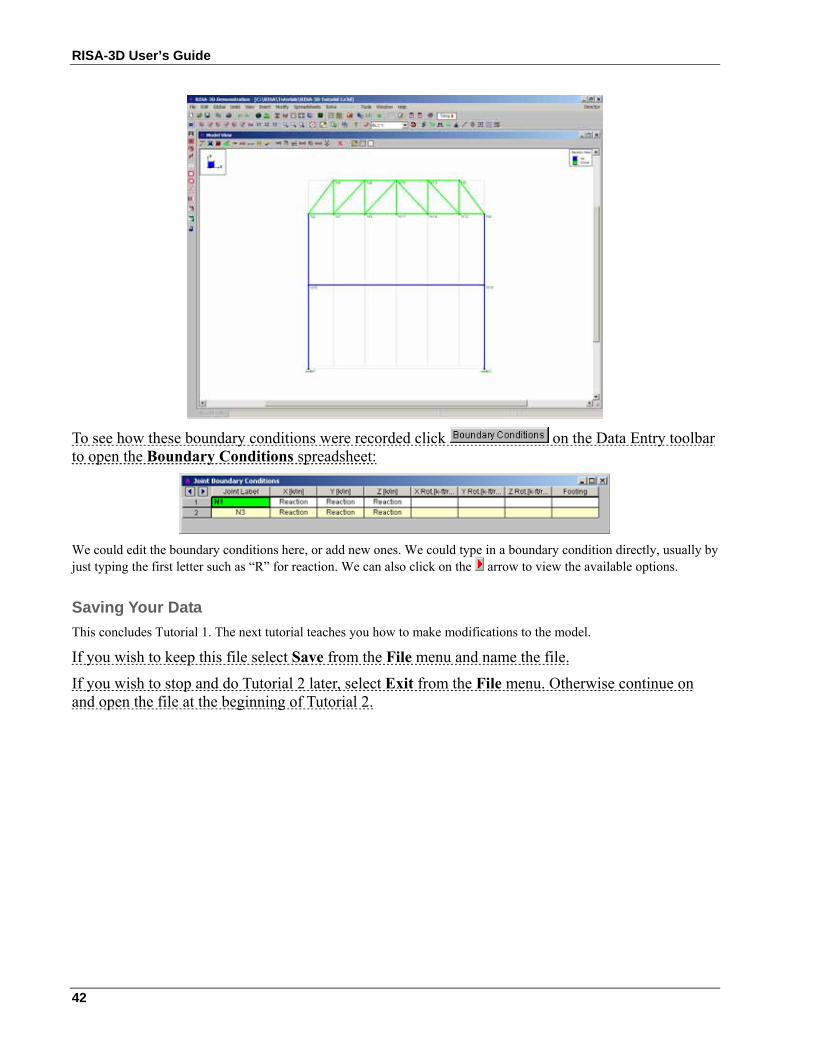
Click on joint N1 and then on joint N3. We are finished with the boundary conditions and your screen should look like this:
RISA-3D User’s Guide
42
To see how these boundary conditions were recorded click on the Data Entry toolbar to open the Boundary Conditions spreadsheet:
We could edit the boundary conditions here, or add new ones. We could type in a boundary condition directly, usually by just typing the first letter such as “R” for reaction. We can also click on the arrow to view the available options.
Saving Your Data This concludes Tutorial 1. The next tutorial teaches you how to make modifications to the model.
If you wish to keep this file select Save from the File menu and name the file.
If you wish to stop and do Tutorial 2 later, select Exit from the File menu. Otherwise continue on and open the file at the beginning of Tutorial 2.
Tutorial 2 – Modifying
43
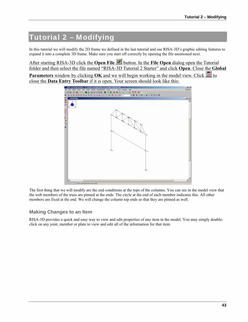
Tutorial 2 – Modifying In this tutorial we will modify the 2D frame we defined in the last tutorial and use RISA-3D’s graphic editing features to expand it into a complete 3D frame. Make sure you start off correctly by opening the file mentioned next.
After starting RISA-3D click the Open File button. In the File Open dialog open the Tutorial folder and then select the file named “RISA-3D Tutorial 2 Starter” and click Open. Close the Global Parameters window by clicking OK and we will begin working in the model view. Click to close the Data Entry Toolbar if it is open. Your screen should look like this:
The first thing that we will modify are the end conditions at the tops of the columns. You can see in the model view that the web members of the truss are pinned at the ends. The circle at the end of each member indicates this. All other members are fixed at the end. We will change the column top ends so that they are pinned as well.
Making Changes to an Item RISA-3D provides a quick and easy way to view and edit properties of any item in the model. You may simply double-click on any joint, member or plate to view and edit all of the information for that item.
RISA-3D User’s Guide
44
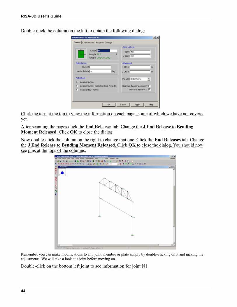
Double-click the column on the left to obtain the following dialog:
Click the tabs at the top to view the information on each page, some of which we have not covered yet.
After scanning the pages click the End Releases tab. Change the J End Release to Bending Moment Released. Click OK to close the dialog.
Now double-click the column on the right to change that one. Click the End Releases tab. Change the J End Release to Bending Moment Released. Click OK to close the dialog. You should now see pins at the tops of the columns.
Remember you can make modifications to any joint, member or plate simply by double-clicking on it and making the adjustments. We will take a look at a joint before moving on.
Double-click on the bottom left joint to see information for joint N1.
Tutorial 2 – Modifying
45
Changing one or two items in the model is best handled in this manner. However, if you had to change a lot of members there is an easier way. This is where the graphical selection and editing tools in RISA-3D become very useful. Let’s learn more about the model view and how we can best put it to use.
Close the dialog without making any changes by clicking Cancel.
Model View Next we will learn how we can modify the model view. Since we are currently working in a model view the Window toolbar will look like this:
The first button is the Set Plot Options button. You have already used this to color the members. We will save this button for last, as it is an important one and will get a lot of attention.
Rotating
These buttons; , are used to rotate the model plot counter-clockwise or clockwise about the global axes.
These buttons; , are used to “snap” the view to the particular plane (XY , YZ , XZ). The button labeled Iso snaps to the default isometric view.
The best way to understand what these buttons do is to try them, so, with the mouse, click on some of these buttons and experiment with rotating and snapping the plot. As you click on these buttons, look at how the plot is rotating. Also look at the axes orientation shown in the top left hand corner of the model view window. That's this box:
When you're finished experimenting place the model in an isometric view by clicking .
Zooming
These buttons; , are used to zoom the model view in and out. This button; , is used to zoom in on part of the model. To use this option, first click on this button, then move the mouse over to the model plot. You will then draw a window around the part of the model you wish to zoom by holding down the left mouse button while dragging the mouse. Press and hold down the left mouse button and then start moving the mouse. You will see a box drawn from the anchor point to the mouse. Move the mouse such that the part of the model you wish to zoom in on is enclosed in the box, then let the mouse button go.
You can cancel the box zoom by dragging the mouse off of the model view window area.
Go ahead and try a box zoom now.
The other two buttons, and , zoom in or out on the model as a whole. The actual zooming is towards the center of the model view. You would typically use the box zoom to get to an area of interest and then use these buttons to adjust the magnification.
If your mouse has a center wheel, RISA-3D also offers a feature that allows you to zoom in on a particular point. Simply place the cursor on the point you wish to zoom in on and rotate the mouse wheel forward. Rotate the wheel backwards to zoom back out.
RISA-3D User’s Guide
46
Also, if you have a mouse wheel, RISA-3D supports a “grab and move” feature. Simply press down on the wheel (like a button) and move the mouse. RISA-3D “grabs” the image at the current cursor location and moves the image with the mouse.
Try these buttons and see what they do. After you are finished click the Full Model View button.
Editing
This button, , is used to toggle the Drawing Toolbar on and off in the current model view. Remember you can have more than one view of the model open at one time and clicking this button will only affect the current view.
Click the button a few times to see what it does and when you are finished leave the Drawing toolbar ON.
Saving Views
You may use to save a view or recall a saved view. If you have a view that you like to work with a lot or have created a view that took some time, save it. Simply click this button and give the view a name. All of the plot options are saved with the model for later recall.
Cloning Views
You can clone a view by clicking . Cloning a view creates a new model view that is identical to the first. This allows you to preserve a view that you want to keep and make adjustments in the new view. We will clone our current view and then use the new view to explore the rest of the toolbar.
Click to clone the view and move the new window into view by dragging the titlebar. You are now working in a new view and the old one is preserved.
Help
We mentioned the help button when we were working with the spreadsheets. Remember, this help button will open the help file to the topic that you are currently working in. If you were to click this button while in a model view the help file would open in the “Navigating Graphics” topic.
Loads
The next three items, , are provided to help you view the loads. We will come back to this once we have defined our loads.
Toggling Items On and Off The remaining buttons are toggles and will control information in the new view.
Click to toggle model rendering. We’ll cover rendering later on.
Click to toggle the joint labels.
Click to toggle the member labels.
Click to toggle the boundaries.
Click to toggle the global axes orientation on and off in the view.
Click to toggle the I-J end flags.
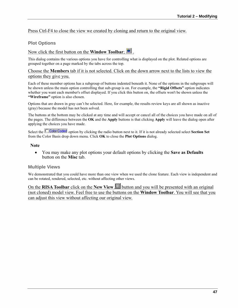
Tutorial 2 – Modifying
47
Press Ctrl-F4 to close the view we created by cloning and return to the original view.
Plot Options
Now click the first button on the Window Toolbar; . This dialog contains the various options you have for controlling what is displayed on the plot. Related options are grouped together on a page marked by the tabs across the top.
Choose the Members tab if it is not selected. Click on the down arrow next to the lists to view the options they give you. Each of these member options has a subgroup of buttons indented beneath it. None of the options in the subgroups will be shown unless the main option controlling that sub-group is on. For example, the “Rigid Offsets” option indicates whether you want each member's offset displayed. If you click this button on, the offsets won't be shown unless the “Wireframe” option is also chosen.
Options that are drawn in gray can’t be selected. Here, for example, the results review keys are all shown as inactive (gray) because the model has not been solved.
The buttons at the bottom may be clicked at any time and will accept or cancel all of the choices you have made on all of the pages. The difference between the OK and the Apply buttons is that clicking Apply will leave the dialog open after applying the choices you have made.
Select the option by clicking the radio button next to it. If it is not already selected select Section Set from the Color Basis drop down menu. Click OK to close the Plot Options dialog.
Note • You may make any plot options your default options by clicking the Save as Defaults
button on the Misc tab.
Multiple Views We demonstrated that you could have more than one view when we used the clone feature. Each view is independent and can be rotated, rendered, selected, etc. without affecting other views.
On the RISA Toolbar click on the New View button and you will be presented with an original (not cloned) model view. Feel free to use the buttons on the Window Toolbar. You will see that you can adjust this view without affecting our original view.
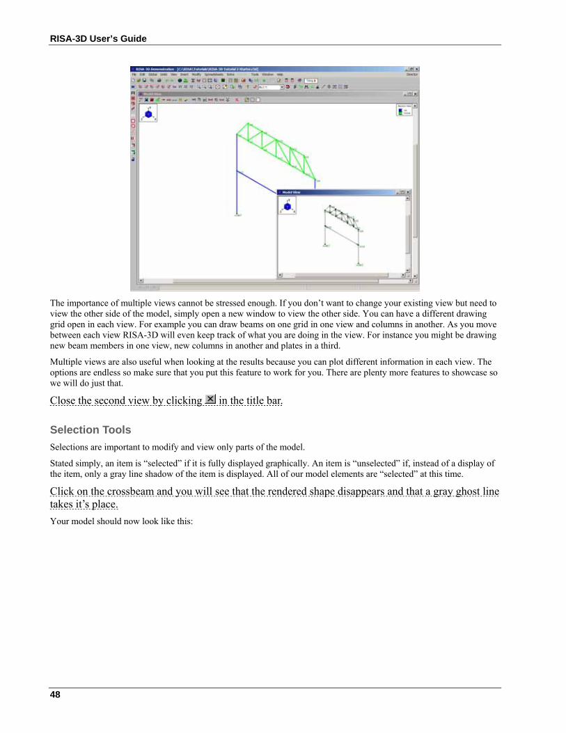
RISA-3D User’s Guide
48
The importance of multiple views cannot be stressed enough. If you don’t want to change your existing view but need to view the other side of the model, simply open a new window to view the other side. You can have a different drawing grid open in each view. For example you can draw beams on one grid in one view and columns in another. As you move between each view RISA-3D will even keep track of what you are doing in the view. For instance you might be drawing new beam members in one view, new columns in another and plates in a third.
Multiple views are also useful when looking at the results because you can plot different information in each view. The options are endless so make sure that you put this feature to work for you. There are plenty more features to showcase so we will do just that.
Close the second view by clicking in the title bar.
Selection Tools Selections are important to modify and view only parts of the model.
Stated simply, an item is “selected” if it is fully displayed graphically. An item is “unselected” if, instead of a display of the item, only a gray line shadow of the item is displayed. All of our model elements are “selected” at this time.
Click on the crossbeam and you will see that the rendered shape disappears and that a gray ghost line takes it’s place. Your model should now look like this:
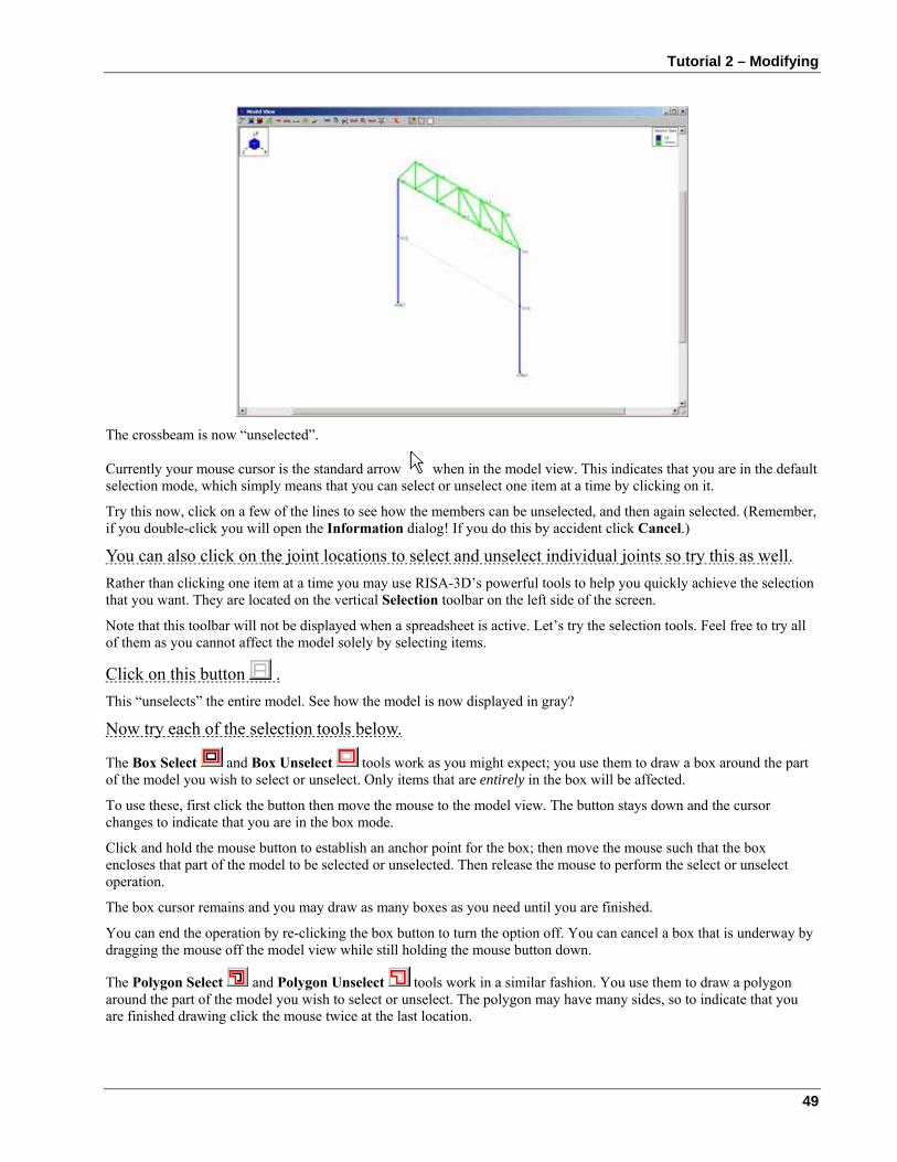
Tutorial 2 – Modifying
49
The crossbeam is now “unselected”.
Currently your mouse cursor is the standard arrow when in the model view. This indicates that you are in the default selection mode, which simply means that you can select or unselect one item at a time by clicking on it.
Try this now, click on a few of the lines to see how the members can be unselected, and then again selected. (Remember, if you double-click you will open the Information dialog! If you do this by accident click Cancel.)
You can also click on the joint locations to select and unselect individual joints so try this as well. Rather than clicking one item at a time you may use RISA-3D’s powerful tools to help you quickly achieve the selection that you want. They are located on the vertical Selection toolbar on the left side of the screen.
Note that this toolbar will not be displayed when a spreadsheet is active. Let’s try the selection tools. Feel free to try all of them as you cannot affect the model solely by selecting items.
Click on this button . This “unselects” the entire model. See how the model is now displayed in gray?
Now try each of the selection tools below.
The Box Select and Box Unselect tools work as you might expect; you use them to draw a box around the part of the model you wish to select or unselect. Only items that are entirely in the box will be affected.
To use these, first click the button then move the mouse to the model view. The button stays down and the cursor changes to indicate that you are in the box mode.
Click and hold the mouse button to establish an anchor point for the box; then move the mouse such that the box encloses that part of the model to be selected or unselected. Then release the mouse to perform the select or unselect operation.
The box cursor remains and you may draw as many boxes as you need until you are finished.
You can end the operation by re-clicking the box button to turn the option off. You can cancel a box that is underway by dragging the mouse off the model view while still holding the mouse button down.
The Polygon Select and Polygon Unselect tools work in a similar fashion. You use them to draw a polygon around the part of the model you wish to select or unselect. The polygon may have many sides, so to indicate that you are finished drawing click the mouse twice at the last location.
RISA-3D User’s Guide
50
With the Line Select and Line Unselect tools you simply draw a line through all of the items that you want to select or unselect. Just click and hold the mouse at the start of the line and then draw the line until you release the mouse button. This is a great tool for selecting the columns or the web members in the truss.
The Invert Selected option is used to invert, or reverse, the selected state of the model. All selected items are made unselected, and all unselected items are made selected. This can be very useful when just a few items are to be selected in a large model; just click on the desired items to unselect them, then click “Invert Selected” to “flip” the selection.
The Criteria Selection button allows you to select items in ways other than choosing them on the screen. You can select items between certain coordinates. You can also select items by their labels such as all joints from N7 to N15. For members, you can select by many criteria such as orientation, section set, database shape and material. Plates can be selected by material, thickness and orientation.
The Save/Recall button is used to save and recall selection states for the model. This is very helpful for large models that require more than just a few clicks to obtain a particular selection state.
The Lock Unselected button, when pressed, causes all currently unselected items to stay unselected, no matter what other selection buttons are pressed, until this button is pressed again. This is useful when you are working on just part of a model, say one particular floor in a multistory building, and you need to select and unselect different parts of that floor and you want the rest of the model to “stay out of the way”. Just unselect the entire model, then use Box Select to select the floor, then press “Lock Unselected” (the button changes to ) and the rest of the model will stay unselected until you press “Lock Unselected” again to turn it off.
When you are finished trying all of the selection tools make sure that the Lock Unselected button is up and looks like this: Now that we know about the selection tools we can use them to help modify the model.
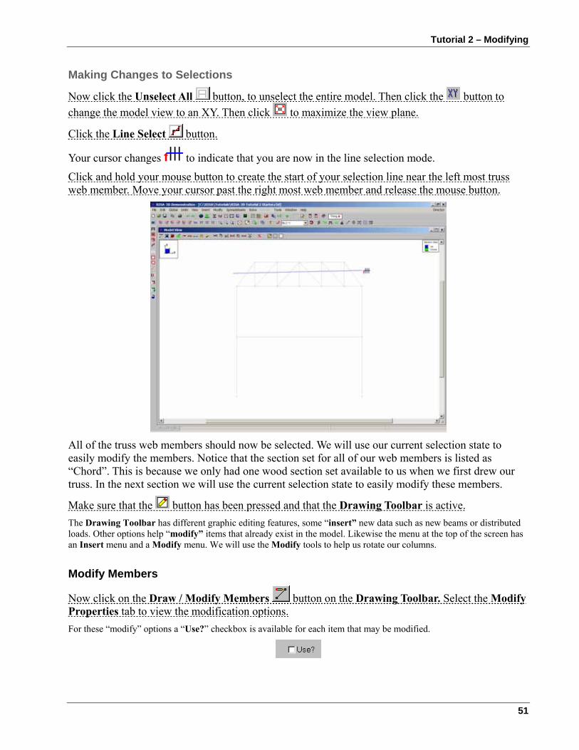
Tutorial 2 – Modifying
51
Making Changes to Selections
Now click the Unselect All button, to unselect the entire model. Then click the button to change the model view to an XY. Then click to maximize the view plane.
Click the Line Select button.
Your cursor changes to indicate that you are now in the line selection mode.
Click and hold your mouse button to create the start of your selection line near the left most truss web member. Move your cursor past the right most web member and release the mouse button.
All of the truss web members should now be selected. We will use our current selection state to easily modify the members. Notice that the section set for all of our web members is listed as “Chord”. This is because we only had one wood section set available to us when we first drew our truss. In the next section we will use the current selection state to easily modify these members.
Make sure that the button has been pressed and that the Drawing Toolbar is active. The Drawing Toolbar has different graphic editing features, some “insert” new data such as new beams or distributed loads. Other options help “modify” items that already exist in the model. Likewise the menu at the top of the screen has an Insert menu and a Modify menu. We will use the Modify tools to help us rotate our columns.
Modify Members
Now click on the Draw / Modify Members button on the Drawing Toolbar. Select the Modify Properties tab to view the modification options. For these “modify” options a “Use?” checkbox is available for each item that may be modified.
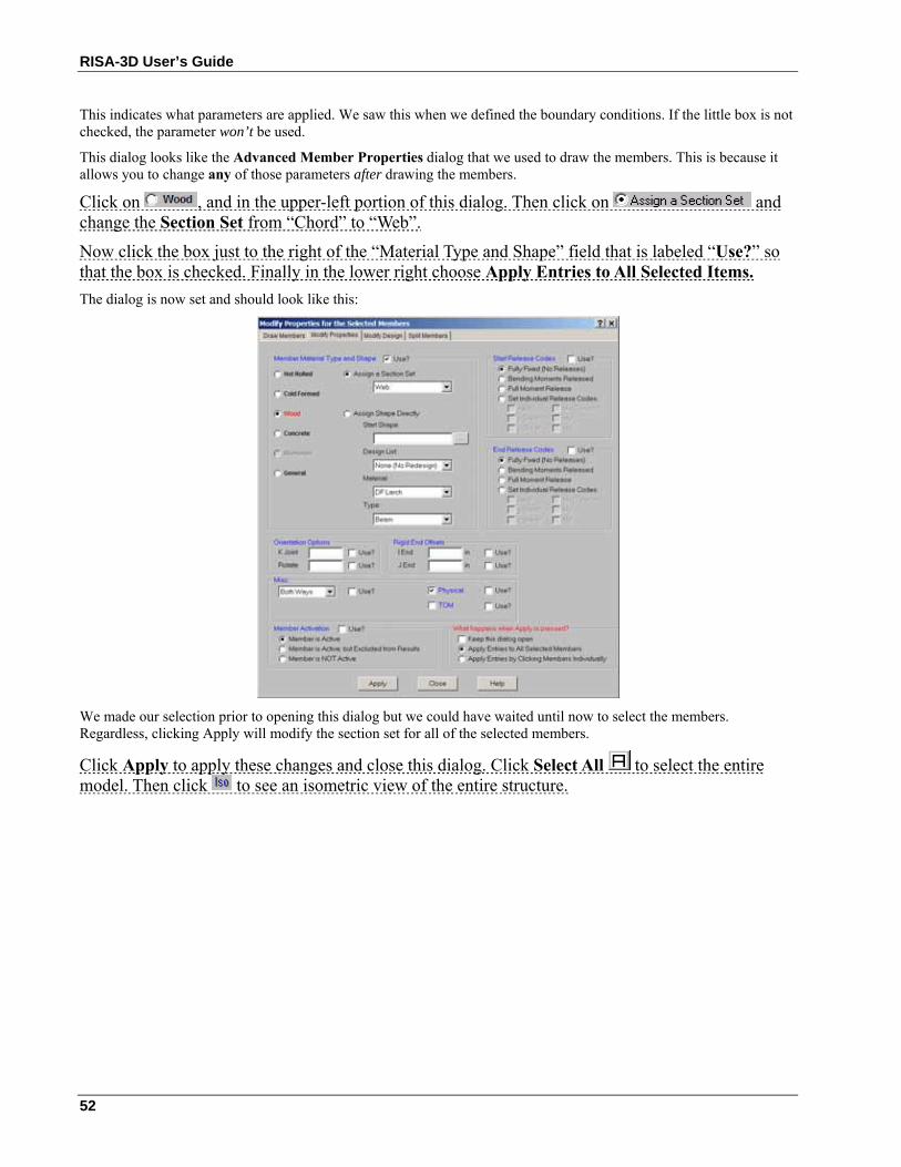
RISA-3D User’s Guide
52
This indicates what parameters are applied. We saw this when we defined the boundary conditions. If the little box is not checked, the parameter won’t be used.
This dialog looks like the Advanced Member Properties dialog that we used to draw the members. This is because it allows you to change any of those parameters after drawing the members.
Click on , and in the upper-left portion of this dialog. Then click on and change the Section Set from “Chord” to “Web”.
Now click the box just to the right of the “Material Type and Shape” field that is labeled “Use?” so that the box is checked. Finally in the lower right choose Apply Entries to All Selected Items. The dialog is now set and should look like this:
We made our selection prior to opening this dialog but we could have waited until now to select the members. Regardless, clicking Apply will modify the section set for all of the selected members.
Click Apply to apply these changes and close this dialog. Click Select All to select the entire model. Then click to see an isometric view of the entire structure.
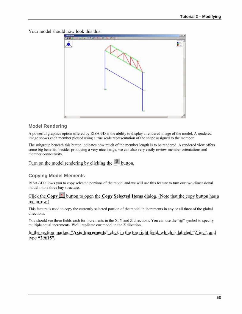
Tutorial 2 – Modifying
53
Your model should now look this this:
Model Rendering A powerful graphics option offered by RISA-3D is the ability to display a rendered image of the model. A rendered image shows each member plotted using a true scale representation of the shape assigned to the member.
The subgroup beneath this button indicates how much of the member length is to be rendered. A rendered view offers some big benefits; besides producing a very nice image, we can also very easily review member orientations and member connectivity.
Turn on the model rendering by clicking the button.
Copying Model Elements RISA-3D allows you to copy selected portions of the model and we will use this feature to turn our two-dimensional model into a three bay structure.
Click the Copy button to open the Copy Selected Items dialog. (Note that the copy button has a red arrow.) This feature is used to copy the currently selected portion of the model in increments in any or all three of the global directions.
You should see three fields each for increments in the X, Y and Z directions. You can use the “@” symbol to specify multiple equal increments. We’ll replicate our model in the Z direction.
In the section marked “Axis Increments” click in the top right field, which is labeled “Z inc”, and type “2@15”.
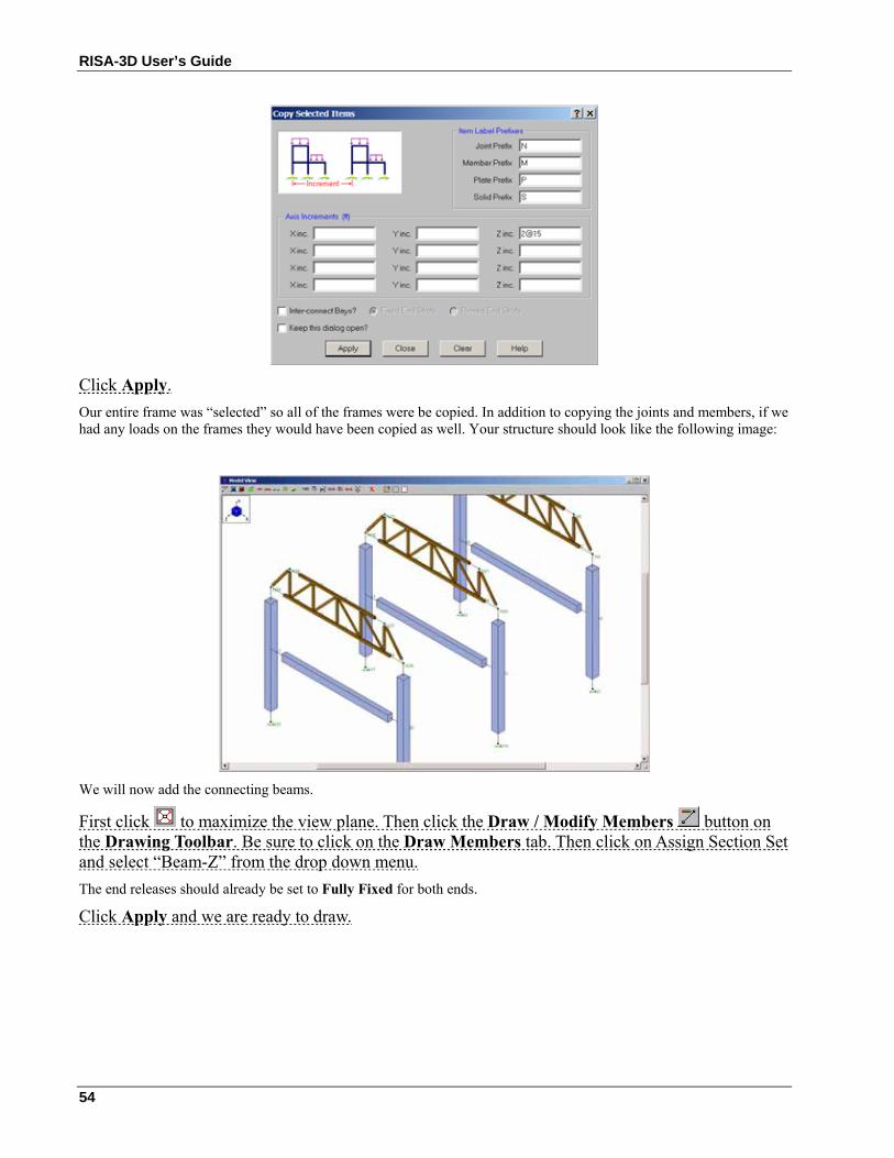
RISA-3D User’s Guide
54
Click Apply. Our entire frame was “selected” so all of the frames were be copied. In addition to copying the joints and members, if we had any loads on the frames they would have been copied as well. Your structure should look like the following image:
We will now add the connecting beams.
First click to maximize the view plane. Then click the Draw / Modify Members button on the Drawing Toolbar. Be sure to click on the Draw Members tab. Then click on Assign Section Set and select “Beam-Z” from the drop down menu. The end releases should already be set to Fully Fixed for both ends.
Click Apply and we are ready to draw.
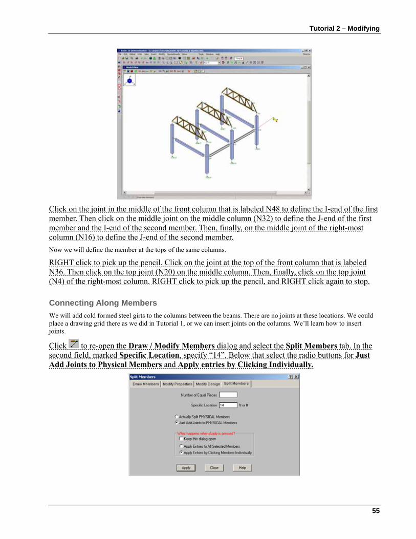
Tutorial 2 – Modifying
55
Click on the joint in the middle of the front column that is labeled N48 to define the I-end of the first member. Then click on the middle joint on the middle column (N32) to define the J-end of the first member and the I-end of the second member. Then, finally, on the middle joint of the right-most column (N16) to define the J-end of the second member. Now we will define the member at the tops of the same columns.
RIGHT click to pick up the pencil. Click on the joint at the top of the front column that is labeled N36. Then click on the top joint (N20) on the middle column. Then, finally, click on the top joint (N4) of the right-most column. RIGHT click to pick up the pencil, and RIGHT click again to stop.
Connecting Along Members We will add cold formed steel girts to the columns between the beams. There are no joints at these locations. We could place a drawing grid there as we did in Tutorial 1, or we can insert joints on the columns. We’ll learn how to insert joints.
Click to re-open the Draw / Modify Members dialog and select the Split Members tab. In the second field, marked Specific Location, specify “14”. Below that select the radio buttons for Just Add Joints to Physical Members and Apply entries by Clicking Individually.
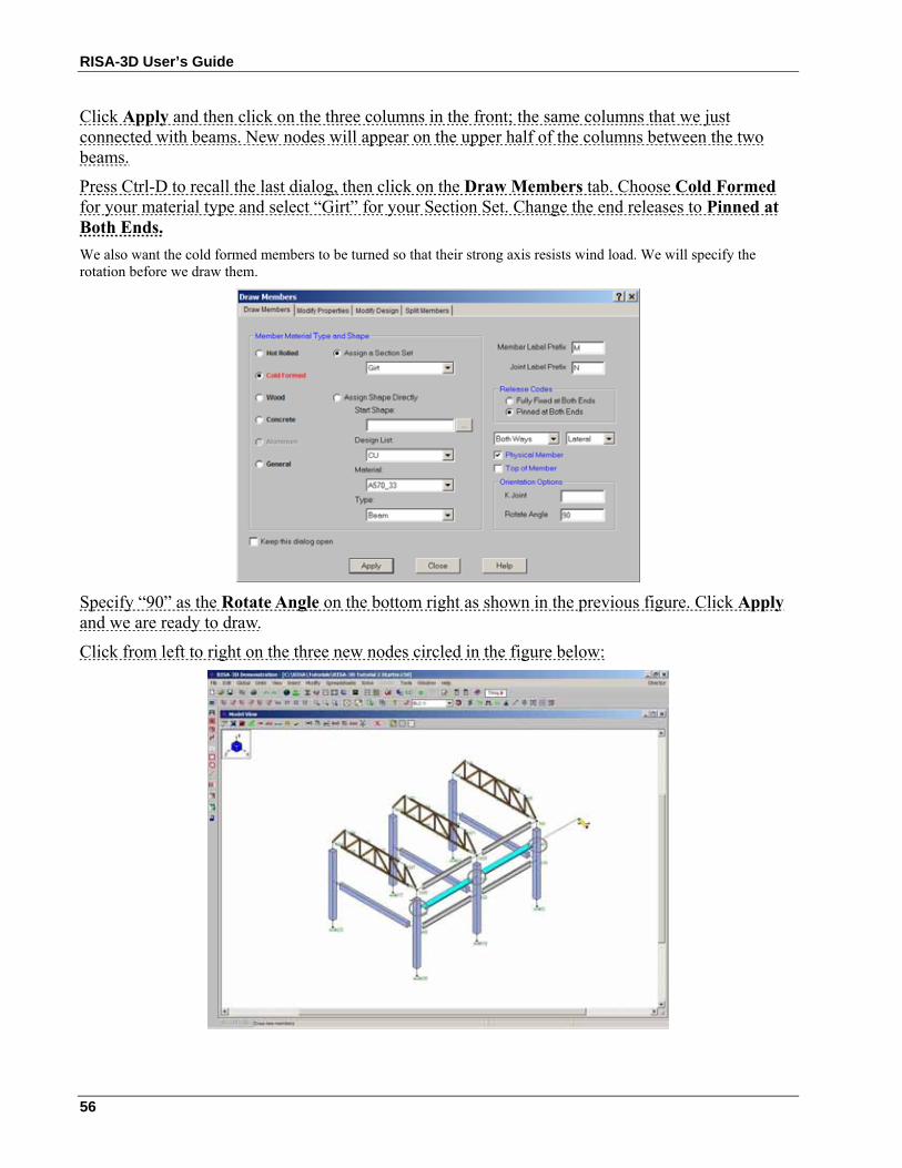
RISA-3D User’s Guide
56
Click Apply and then click on the three columns in the front; the same columns that we just connected with beams. New nodes will appear on the upper half of the columns between the two beams.
Press Ctrl-D to recall the last dialog, then click on the Draw Members tab. Choose Cold Formed for your material type and select “Girt” for your Section Set. Change the end releases to Pinned at Both Ends. We also want the cold formed members to be turned so that their strong axis resists wind load. We will specify the rotation before we draw them.
Specify “90” as the Rotate Angle on the bottom right as shown in the previous figure. Click Apply and we are ready to draw.
Click from left to right on the three new nodes circled in the figure below:
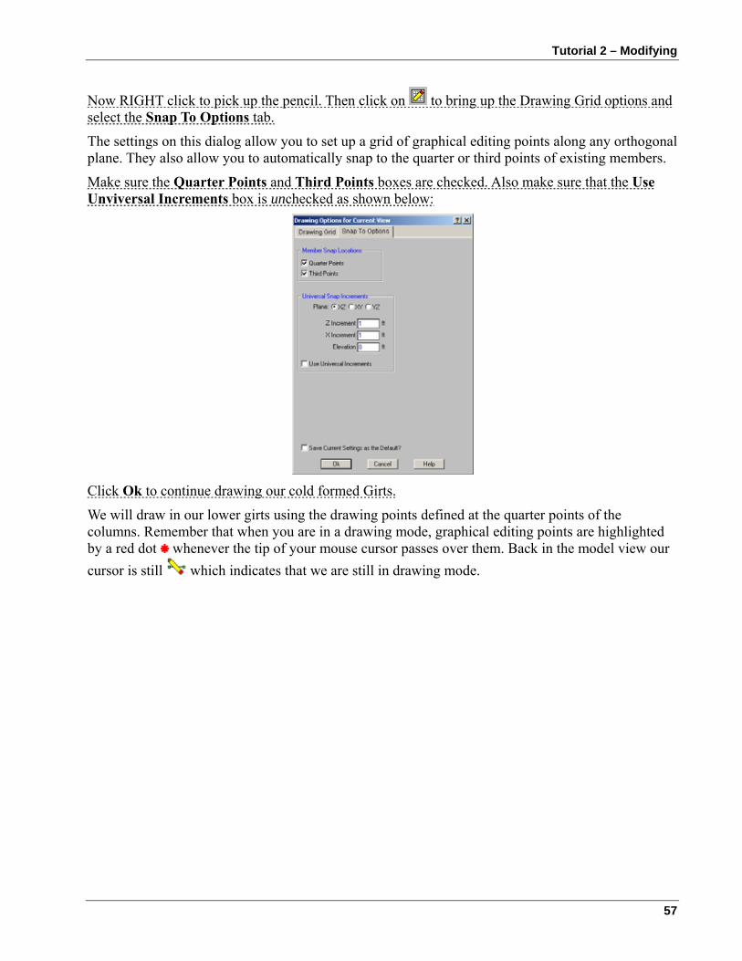
Tutorial 2 – Modifying
57
Now RIGHT click to pick up the pencil. Then click on to bring up the Drawing Grid options and select the Snap To Options tab.
The settings on this dialog allow you to set up a grid of graphical editing points along any orthogonal plane. They also allow you to automatically snap to the quarter or third points of existing members.
Make sure the Quarter Points and Third Points boxes are checked. Also make sure that the Use Unviversal Increments box is unchecked as shown below:
Click Ok to continue drawing our cold formed Girts.
We will draw in our lower girts using the drawing points defined at the quarter points of the columns. Remember that when you are in a drawing mode, graphical editing points are highlighted by a red dot whenever the tip of your mouse cursor passes over them. Back in the model view our cursor is still which indicates that we are still in drawing mode.
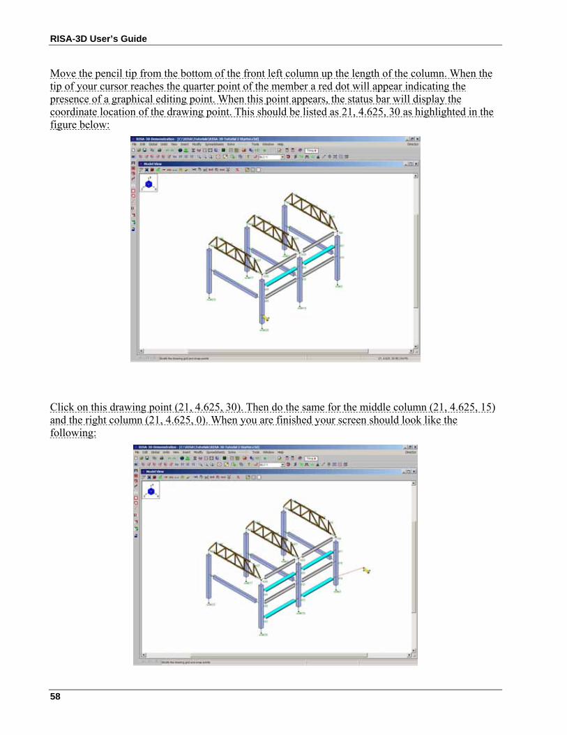
RISA-3D User’s Guide
58
Move the pencil tip from the bottom of the front left column up the length of the column. When the tip of your cursor reaches the quarter point of the member a red dot will appear indicating the presence of a graphical editing point. When this point appears, the status bar will display the coordinate location of the drawing point. This should be listed as 21, 4.625, 30 as highlighted in the figure below:
Click on this drawing point (21, 4.625, 30). Then do the same for the middle column (21, 4.625, 15) and the right column (21, 4.625, 0). When you are finished your screen should look like the following:
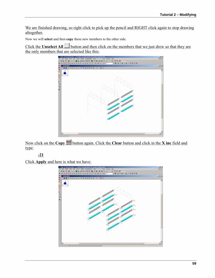
Tutorial 2 – Modifying
59
We are finished drawing, so right click to pick up the pencil and RIGHT click again to stop drawing altogether. Now we will select and then copy these new members to the other side.
Click the Unselect All button and then click on the members that we just drew so that they are the only members that are selected like this:
Now click on the Copy button again. Click the Clear button and click in the X inc field and type:
-21 Click Apply and here is what we have:
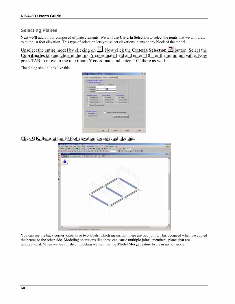
RISA-3D User’s Guide
60
Selecting Planes Next we’ll add a floor composed of plate elements. We will use Criteria Selection to select the joints that we will draw to at the 10 foot elevation. This type of selection lets you select elevations, plans or any block of the model.
Unselect the entire model by clicking on . Now click the Criteria Selection button. Select the Coordinates tab and click in the first Y coordinate field and enter “10” for the minimum value. Now press TAB to move to the maximum Y coordinate and enter “10” there as well. The dialog should look like this:
Click OK. Items at the 10 foot elevation are selected like this:
You can see the back corner joints have two labels, which means that there are two joints. This occurred when we copied the beams to the other side. Modeling operations like these can cause multiple joints, members, plates that are unintentional. When we are finished modeling we will use the Model Merge feature to clean up our model.
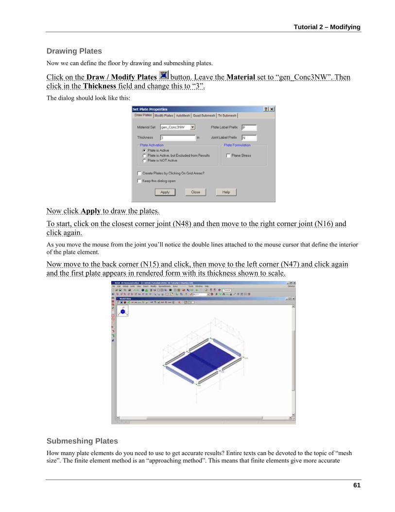
Tutorial 2 – Modifying
61
Drawing Plates Now we can define the floor by drawing and submeshing plates.
Click on the Draw / Modify Plates button. Leave the Material set to “gen_Conc3NW”. Then click in the Thickness field and change this to “3”. The dialog should look like this:
Now click Apply to draw the plates.
To start, click on the closest corner joint (N48) and then move to the right corner joint (N16) and click again. As you move the mouse from the joint you’ll notice the double lines attached to the mouse cursor that define the interior of the plate element.
Now move to the back corner (N15) and click, then move to the left corner (N47) and click again and the first plate appears in rendered form with its thickness shown to scale.
Submeshing Plates How many plate elements do you need to use to get accurate results? Entire texts can be devoted to the topic of “mesh size”. The finite element method is an “approaching method”. This means that finite elements give more accurate
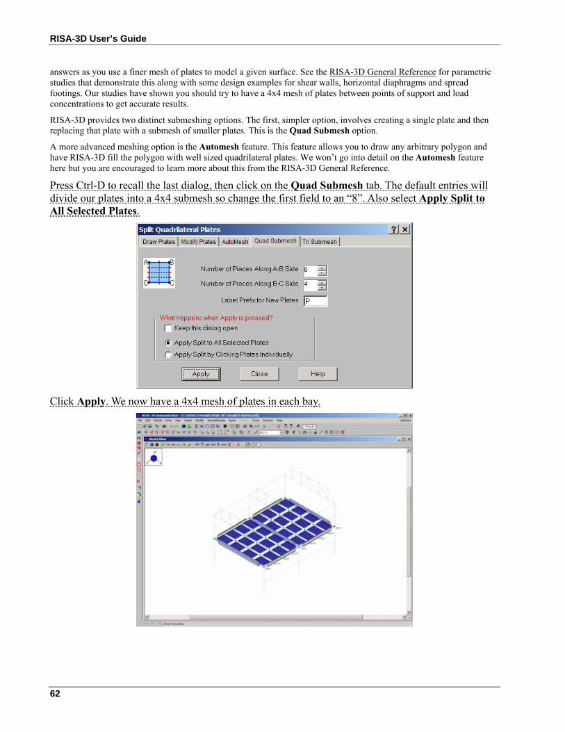
RISA-3D User’s Guide
62
answers as you use a finer mesh of plates to model a given surface. See the RISA-3D General Reference for parametric studies that demonstrate this along with some design examples for shear walls, horizontal diaphragms and spread footings. Our studies have shown you should try to have a 4x4 mesh of plates between points of support and load concentrations to get accurate results.
RISA-3D provides two distinct submeshing options. The first, simpler option, involves creating a single plate and then replacing that plate with a submesh of smaller plates. This is the Quad Submesh option.
A more advanced meshing option is the Automesh feature. This feature allows you to draw any arbitrary polygon and have RISA-3D fill the polygon with well sized quadrilateral plates. We won’t go into detail on the Automesh feature here but you are encouraged to learn more about this from the RISA-3D General Reference.
Press Ctrl-D to recall the last dialog, then click on the Quad Submesh tab. The default entries will divide our plates into a 4x4 submesh so change the first field to an “8”. Also select Apply Split to All Selected Plates.
Click Apply. We now have a 4x4 mesh of plates in each bay.
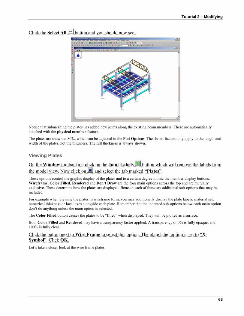
Tutorial 2 – Modifying
63
Click the Select All button and you should now see:
Notice that submeshing the plates has added new joints along the existing beam members. These are automatically attached with the physical member feature.
The plates are shown at 80%, which can be adjusted in the Plot Options. The shrink factors only apply to the length and width of the plates, not the thickness. The full thickness is always shown.
Viewing Plates
On the Window toolbar first click on the Joint Labels button which will remove the labels from the model view. Now click on and select the tab marked “Plates”. These options control the graphic display of the plates and to a certain degree mimic the member display buttons. Wireframe, Color Filled, Rendered and Don’t Draw are the four main options across the top and are mutually exclusive. These determine how the plates are displayed. Beneath each of these are additional sub-options that may be included.
For example when viewing the plates in wireframe form, you may additionally display the plate labels, material set, numerical thickness or local axes alongside each plate. Remember that the indented sub-options below each main option don’t do anything unless the main option is selected.
The Color Filled button causes the plates to be “filled” when displayed. They will be plotted as a surface.
Both Color Filled and Rendered may have a transparency factor applied. A transparency of 0% is fully opaque, and 100% is fully clear.
Click the button next to Wire Frame to select this option. The plate label option is set to “X-Symbol”. Click OK. Let’s take a closer look at the wire frame plates.
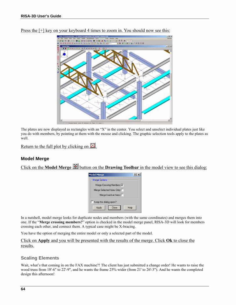
RISA-3D User’s Guide
64
Press the [+] key on your keyboard 4 times to zoom in. You should now see this:
The plates are now displayed as rectangles with an “X” in the center. You select and unselect individual plates just like you do with members, by pointing at them with the mouse and clicking. The graphic selection tools apply to the plates as well.
Return to the full plot by clicking on .
Model Merge
Click on the Model Merge button on the Drawing Toolbar in the model view to see this dialog:
In a nutshell, model merge looks for duplicate nodes and members (with the same coordinates) and merges them into one. If the “Merge crossing members?” option is checked in the model merge panel, RISA-3D will look for members crossing each other, and connect them. A typical case might be X-bracing.
You have the option of merging the entire model or only a selected part of the model.
Click on Apply and you will be presented with the results of the merge. Click Ok to close the results.
Scaling Elements Wait, what’s that coming in on the FAX machine?! The client has just submitted a change order! He wants to raise the wood truss from 18'-6" to 22'-9", and he wants the frame 25% wider (from 21' to 26'-3"). And he wants the completed design this afternoon!
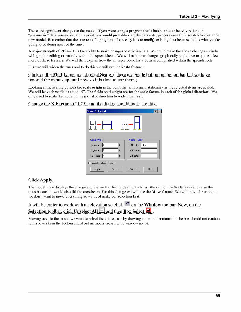
Tutorial 2 – Modifying
65
These are significant changes to the model. If you were using a program that’s batch input or heavily reliant on “parametric” data generators, at this point you would probably start the data entry process over from scratch to create the new model. Remember that the true test of a program is how easy it is to modify existing data because that is what you’re going to be doing most of the time.
A major strength of RISA-3D is the ability to make changes to existing data. We could make the above changes entirely with graphic editing or entirely within the spreadsheets. We will make our changes graphically so that we may use a few more of these features. We will then explain how the changes could have been accomplished within the spreadsheets.
First we will widen the truss and to do this we will use the Scale feature.
Click on the Modify menu and select Scale. (There is a Scale button on the toolbar but we have ignored the menus up until now so it is time to use them.) Looking at the scaling options the scale origin is the point that will remain stationary as the selected items are scaled. We will leave these fields set to “0”. The fields on the right are for the scale factors in each of the global directions. We only need to scale the model in the global X direction to widen the truss.
Change the X Factor to “1.25” and the dialog should look like this:
Click Apply. The model view displays the change and we are finished widening the truss. We cannot use Scale feature to raise the truss because it would also lift the crossbeam. For this change we will use the Move feature. We will move the truss but we don’t want to move everything so we need make our selection first.
It will be easier to work with an elevation so click on the Window toolbar. Now, on the Selection toolbar, click Unselect All and then Box Select . Moving over to the model we want to select the entire truss by drawing a box that contains it. The box should not contain joints lower than the bottom chord but members crossing the window are ok.
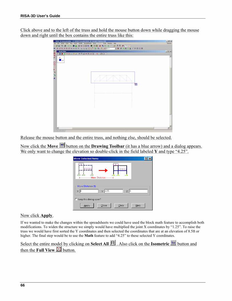
RISA-3D User’s Guide
66
Click above and to the left of the truss and hold the mouse button down while dragging the mouse down and right until the box contains the entire truss like this:
Release the mouse button and the entire truss, and nothing else, should be selected.
Now click the Move button on the Drawing Toolbar (it has a blue arrow) and a dialog appears. We only want to change the elevation so double-click in the field labeled Y and type “4.25”.
Now click Apply. If we wanted to make the changes within the spreadsheets we could have used the block math feature to accomplish both modifications. To widen the structure we simply would have multiplied the joint X coordinates by “1.25”. To raise the truss we would have first sorted the Y coordinates and then selected the coordinates that are at an elevation of 8.5ft or higher. The final step would be to use the Math feature to add “4.25” to these selected Y coordinates.
Select the entire model by clicking on Select All . Also click on the Isometric button and then the Full View button.
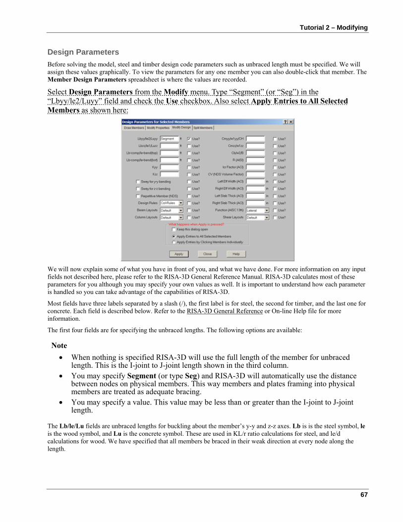
Tutorial 2 – Modifying
67
Design Parameters Before solving the model, steel and timber design code parameters such as unbraced length must be specified. We will assign these values graphically. To view the parameters for any one member you can also double-click that member. The Member Design Parameters spreadsheet is where the values are recorded.
Select Design Parameters from the Modify menu. Type “Segment” (or “Seg”) in the “Lbyy/le2/Luyy” field and check the Use checkbox. Also select Apply Entries to All Selected Members as shown here:
We will now explain some of what you have in front of you, and what we have done. For more information on any input fields not described here, please refer to the RISA-3D General Reference Manual. RISA-3D calculates most of these parameters for you although you may specify your own values as well. It is important to understand how each parameter is handled so you can take advantage of the capabilities of RISA-3D.
Most fields have three labels separated by a slash (/), the first label is for steel, the second for timber, and the last one for concrete. Each field is described below. Refer to the RISA-3D General Reference or On-line Help file for more information.
The first four fields are for specifying the unbraced lengths. The following options are available:
Note • When nothing is specified RISA-3D will use the full length of the member for unbraced
length. This is the I-joint to J-joint length shown in the third column. • You may specify Segment (or type Seg) and RISA-3D will automatically use the distance
between nodes on physical members. This way members and plates framing into physical members are treated as adequate bracing.
• You may specify a value. This value may be less than or greater than the I-joint to J-joint length.
The Lb/le/Lu fields are unbraced lengths for buckling about the member’s y-y and z-z axes. Lb is is the steel symbol, le is the wood symbol, and Lu is the concrete symbol. These are used in KL/r ratio calculations for steel, and le/d calculations for wood. We have specified that all members be braced in their weak direction at every node along the length.

RISA-3D User’s Guide
68
The Lcomp values (used for steel) are the laterally unbraced lengths of the top and bottom flanges used in the calculation of allowable bending stress for ASD design, or member strength for LRFD design. The le-bend values (used for wood) are used in the calculation of RB in NDS wood design.
The K factors are the effective length factors, which RISA-3D is capable of approximating for you. A value of 1.0 will be used when nothing is specified. Refer to the RISA-3D General Reference or On-line Help file for more information.
The Cm factor, used in the calculation of the bending stress ratio for steel ASD design, may be entered if you wish to use a specific value. If left blank it will be calculated exactly by RISA-3D. CH shares the same column as Cmyy and is the NDS shear stress factor.
If you leave the Cb factor blank RISA-3D will calculate it for you.
The R value for cold formed steel design is described in section C3.1.3 of the AISI 1996 Supplement 1 (1999). This value only applies to C or Z members and is used to calculate the moment capacity of beams that have one flange fastened to deck or sheathing.
The sway check boxes are used to indicate whether the member is to be considered subject to sidesway for bending about its y-y and z-z axes. Sway comes into play in the calculation of Cm and Cb and in the approximation of K factors.
If you put a check in the Cr field, a factor of 1.15 will be applied to beam NDS wood members that are 2” to 4” thick. This flag will be ignored for a non wood members or wood members that are thicker than 4”.
Currently, all the entries are blank except for the first. For the fields we left blank RISA-3D will use the default values when the code check calculations are performed. For weak axis bending each node is treated as a brace point as a result of the use of the “Segment” code.
Click Apply.
To actually see the settings for the unbraced lengths we could double-click any member or click Plot Options to show the unbraced lengths in the view.
Sorting Next up we will see how we can sort information in our model. Let’s look at the Joint Coordinates spreadsheet for the first time and let’s use a special window arrangement to do this.
Click the Tiling button on the RISA Toolbar and the following list of window tiling options is presented.
Later on we will experiment with these options. For now, select the second option which is “Joints Input” and click OK. Your screen should look like this:
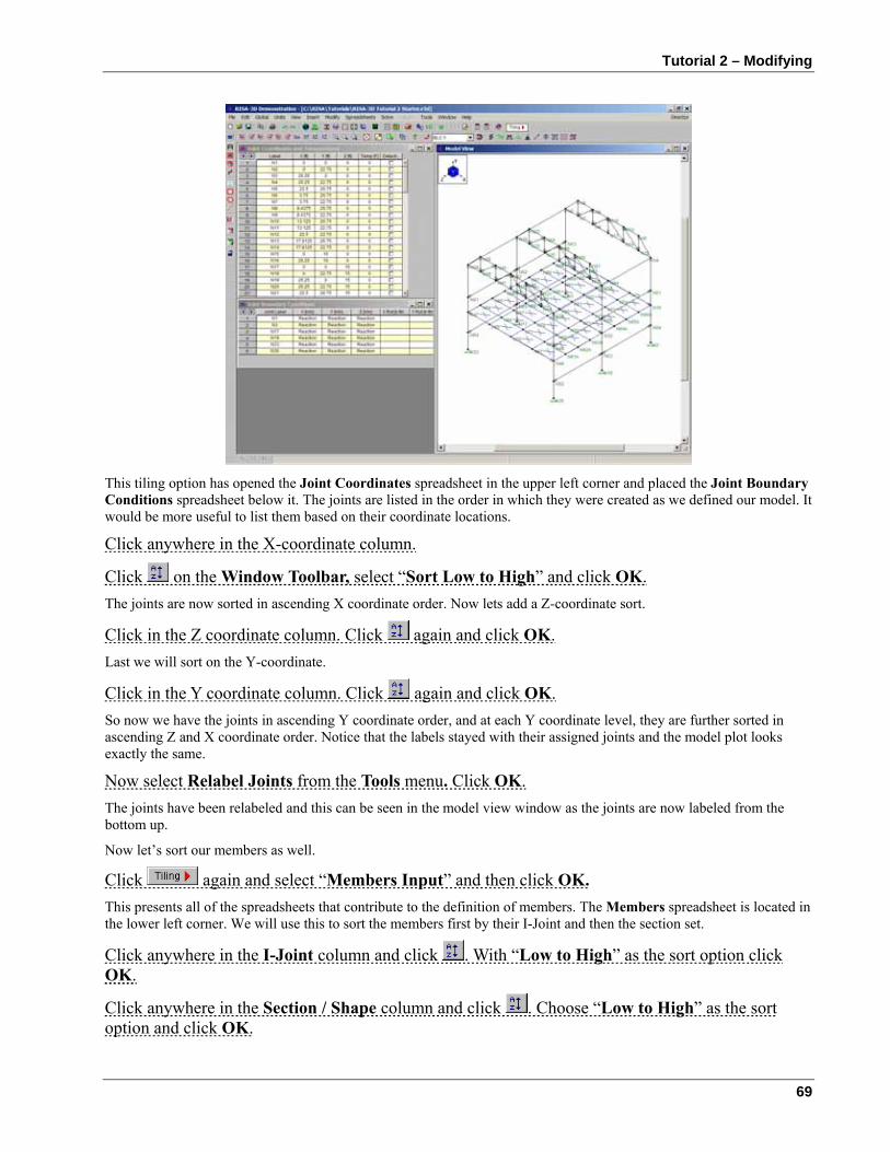
Tutorial 2 – Modifying
69
This tiling option has opened the Joint Coordinates spreadsheet in the upper left corner and placed the Joint Boundary Conditions spreadsheet below it. The joints are listed in the order in which they were created as we defined our model. It would be more useful to list them based on their coordinate locations.
Click anywhere in the X-coordinate column.
Click on the Window Toolbar, select “Sort Low to High” and click OK. The joints are now sorted in ascending X coordinate order. Now lets add a Z-coordinate sort.
Click in the Z coordinate column. Click again and click OK. Last we will sort on the Y-coordinate.
Click in the Y coordinate column. Click again and click OK. So now we have the joints in ascending Y coordinate order, and at each Y coordinate level, they are further sorted in ascending Z and X coordinate order. Notice that the labels stayed with their assigned joints and the model plot looks exactly the same.
Now select Relabel Joints from the Tools menu. Click OK. The joints have been relabeled and this can be seen in the model view window as the joints are now labeled from the bottom up.
Now let’s sort our members as well.
Click again and select “Members Input” and then click OK. This presents all of the spreadsheets that contribute to the definition of members. The Members spreadsheet is located in the lower left corner. We will use this to sort the members first by their I-Joint and then the section set.
Click anywhere in the I-Joint column and click . With “Low to High” as the sort option click OK.
Click anywhere in the Section / Shape column and click . Choose “Low to High” as the sort option and click OK.
RISA-3D User’s Guide
70
Again the member labels remain with the same members and the view has not been affected by the sort because nothing has actually changed other than how the members are arranged in the spreadsheet.
Now select Relabel Members from the Tools menu. Click OK. This sorts our beams by section, making them easier to identify and work with in our next operation, which is assigning parameters for steel and wood design.
This concludes Tutorial 2. The next tutorial teaches you how to load the model.
If you wish to stop and do Tutorial 3 later, select Exit from the File menu. Otherwise continue on and open the file at the beginning of Tutorial 3.
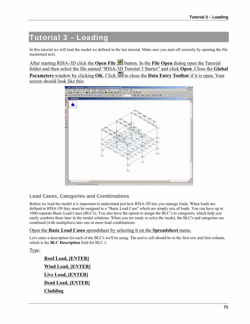
Tutorial 3 – Loading
71
Tutorial 3 – Loading In this tutorial we will load the model we defined in the last tutorial. Make sure you start off correctly by opening the file mentioned next.
After starting RISA-3D click the Open File button. In the File Open dialog open the Tutorial folder and then select the file named “RISA-3D Tutorial 3 Starter” and click Open. Close the Global Parameters window by clicking OK. Click to close the Data Entry Toolbar if it is open. Your screen should look like this:
Load Cases, Categories and Combinations Before we load the model it is important to understand just how RISA-3D lets you manage loads. When loads are defined in RISA-3D they must be assigned to a “Basic Load Case” which are simply sets of loads. You can have up to 1000 separate Basic Load Cases (BLC's). You also have the option to assign the BLC’s to categories, which help you easily combine them later in the model solutions. When you are ready to solve the model, the BLC's and categories are combined (with multipliers) into one or more load combinations.
Open the Basic Load Cases spreadsheet by selecting it on the Spreadsheet menu. Let's enter a description for each of the BLC's we'll be using. The active cell should be in the first row and first column, which is the BLC Description field for BLC 1.
Type:
Roof Load, [ENTER]
Wind Load, [ENTER]
Live Load, [ENTER]
Dead Load, [ENTER]
Cladding
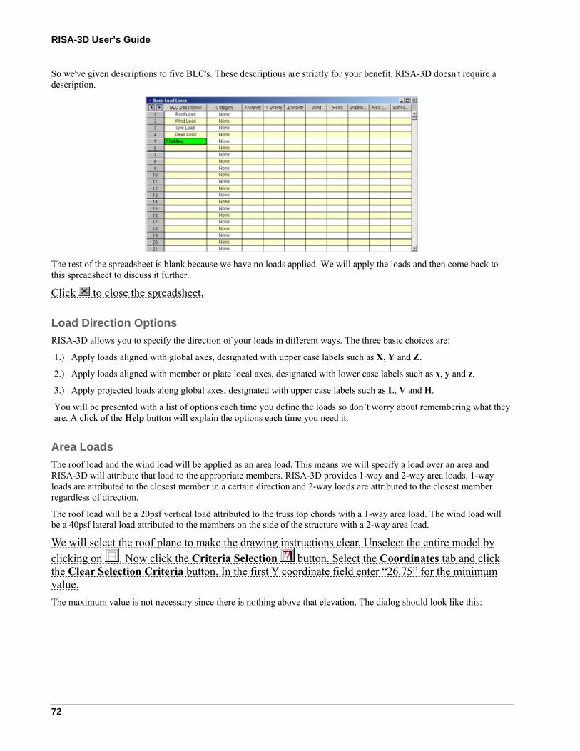
RISA-3D User’s Guide
72
So we've given descriptions to five BLC's. These descriptions are strictly for your benefit. RISA-3D doesn't require a description.
The rest of the spreadsheet is blank because we have no loads applied. We will apply the loads and then come back to this spreadsheet to discuss it further.
Click to close the spreadsheet.
Load Direction Options RISA-3D allows you to specify the direction of your loads in different ways. The three basic choices are:
1.) Apply loads aligned with global axes, designated with upper case labels such as X, Y and Z.
2.) Apply loads aligned with member or plate local axes, designated with lower case labels such as x, y and z.
3.) Apply projected loads along global axes, designated with upper case labels such as L, V and H.
You will be presented with a list of options each time you define the loads so don’t worry about remembering what they are. A click of the Help button will explain the options each time you need it.
Area Loads The roof load and the wind load will be applied as an area load. This means we will specify a load over an area and RISA-3D will attribute that load to the appropriate members. RISA-3D provides 1-way and 2-way area loads. 1-way loads are attributed to the closest member in a certain direction and 2-way loads are attributed to the closest member regardless of direction.
The roof load will be a 20psf vertical load attributed to the truss top chords with a 1-way area load. The wind load will be a 40psf lateral load attributed to the members on the side of the structure with a 2-way area load.
We will select the roof plane to make the drawing instructions clear. Unselect the entire model by clicking on . Now click the Criteria Selection button. Select the Coordinates tab and click the Clear Selection Criteria button. In the first Y coordinate field enter “26.75” for the minimum value. The maximum value is not necessary since there is nothing above that elevation. The dialog should look like this:
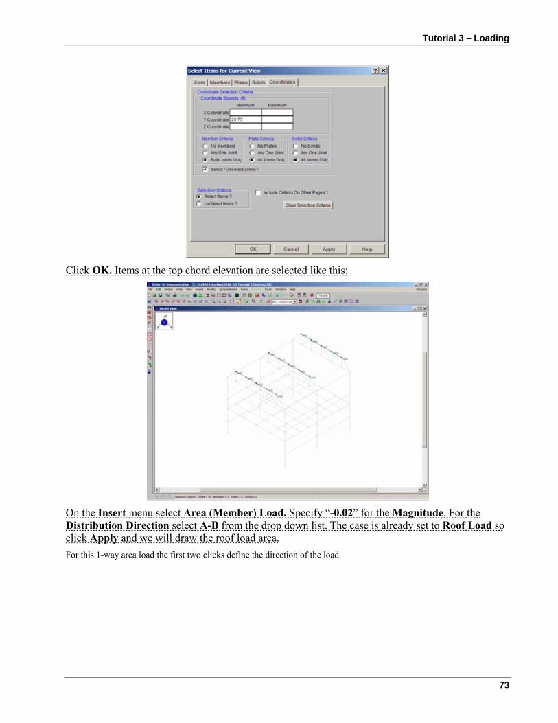
Tutorial 3 – Loading
73
Click OK. Items at the top chord elevation are selected like this:
On the Insert menu select Area (Member) Load. Specify “-0.02” for the Magnitude. For the Distribution Direction select A-B from the drop down list. The case is already set to Roof Load so click Apply and we will draw the roof load area. For this 1-way area load the first two clicks define the direction of the load.
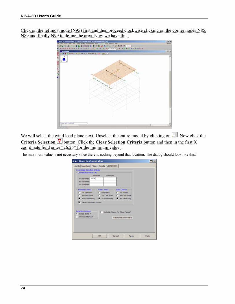
RISA-3D User’s Guide
74
Click on the leftmost node (N95) first and then proceed clockwise clicking on the corner nodes N85, N89 and finally N99 to define the area. Now we have this:
We will select the wind load plane next. Unselect the entire model by clicking on . Now click the Criteria Selection button. Click the Clear Selection Criteria button and then in the first X coordinate field enter “26.25” for the minimum value. The maximum value is not necessary since there is nothing beyond that location. The dialog should look like this:
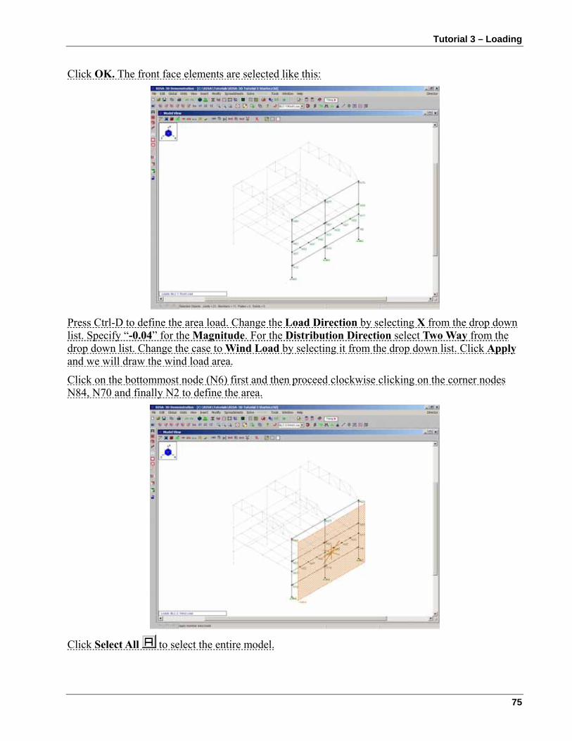
Tutorial 3 – Loading
75
Click OK. The front face elements are selected like this:
Press Ctrl-D to define the area load. Change the Load Direction by selecting X from the drop down list. Specify “-0.04” for the Magnitude. For the Distribution Direction select Two Way from the drop down list. Change the case to Wind Load by selecting it from the drop down list. Click Apply and we will draw the wind load area.
Click on the bottommost node (N6) first and then proceed clockwise clicking on the corner nodes N84, N70 and finally N2 to define the area.
Click Select All to select the entire model.
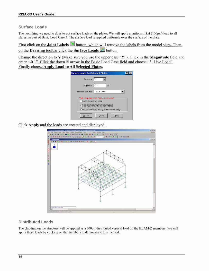
RISA-3D User’s Guide
76
Surface Loads The next thing we need to do is to put surface loads on the plates. We will apply a uniform .1ksf (100psf) load to all plates, as part of Basic Load Case 3. The surface load is applied uniformly over the surface of the plate.
First click on the Joint Labels button, which will remove the labels from the model view. Then, on the Drawing toolbar click the Surface Loads button.
Change the direction to Y (Make sure you use the upper case “Y”). Click in the Magnitude field and enter “-0.1”. Click the down arrow in the Basic Load Case field and choose “3: Live Load”. Finally choose Apply Load to All Selected Plates.
Click Apply and the loads are created and displayed.
Distributed Loads The cladding on the structure will be applied as a 300plf distributed vertical load on the BEAM-Z members. We will apply these loads by clicking on the members to demonstrate this method.
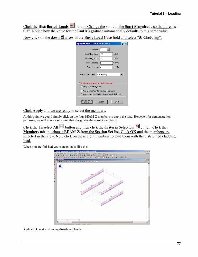
Tutorial 3 – Loading
77
Click the Distributed Loads button. Change the value in the Start Magnitude so that it reads “-0.3”. Notice how the value for the End Magnitude automatically defaults to this same value.
Now click on the down arrow in the Basic Load Case field and select “5: Cladding”.
Click Apply and we are ready to select the members. At this point we could simply click on the four BEAM-Z members to apply the load. However, for demonstration purposes, we will make a selection that designates the correct members.
Click the Unselect All button and then click the Criteria Selection button. Click the Members tab and choose BEAM-Z from the Section Set list. Click OK and the members are selected in the view. Now click on these eight members to load them with the distributed cladding load. When you are finished your screen looks like this:
Right click to stop drawing distributed loads.
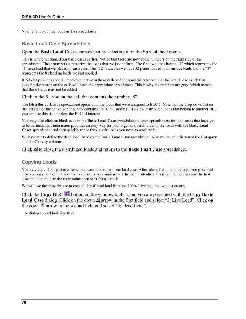
RISA-3D User’s Guide
78
Now let’s look at the loads in the spreadsheets.
Basic Load Case Spreadsheet Open the Basic Load Cases spreadsheet by selecting it on the Spreadsheet menu. This is where we named our basic cases earlier. Notice that there are now some numbers on the right side of the spreadsheet. These numbers summarize the loads that we just defined. The first two lines have a “1” which represents the “1” area load that we placed in each case. The “32” indicates we have 32 plates loaded with surface loads and the “8” represents the 8 cladding loads we just applied.
RISA-3D provides special interaction between these cells and the spreadsheets that hold the actual loads such that clicking the mouse on the cells will open the appropriate spreadsheet. This is why the numbers are gray, which means that these fields may not be edited.
Click in the 5th row on the cell that contains the number “8”. The Distributed Loads spreadsheet opens with the loads that were assigned to BLC 5. Note that the drop-down list on the left side of the active window now contains “BLC 5:Cladding”. To view distributed loads that belong to another BLC you can use this list to select the BLC of interest.
You may also click on blank cells in the Basic Load Case spreadsheet to open spreadsheets for load cases that have yet to be defined. This interaction provides an easy way for you to get an overall view of the loads with the Basic Load Cases spreadsheet and then quickly move through the loads you need to work with.
We have yet to define the dead load listed on the Basic Load Case spreadsheet. Also we haven’t discussed the Category and the Gravity columns.
Click to close the distributed loads and return to the Basic Load Case spreadsheet.
Copying Loads You may copy all or part of a basic load case to another basic load case. After taking the time to define a complex load case you may realize that another load case is very similar to it. In such a situation it is might be best to copy the first case and then modify the copy rather than start from scratch.
We will use the copy feature to create a 90psf dead load from the 100psf live load that we just created.
Click the Copy BLC button on the window toolbar and you are presented with the Copy Basic Load Case dialog. Click on the down arrow in the first field and select “3: Live Load”. Click on the down arrow in the second field and select “4: Dead Load”. The dialog should look like this:
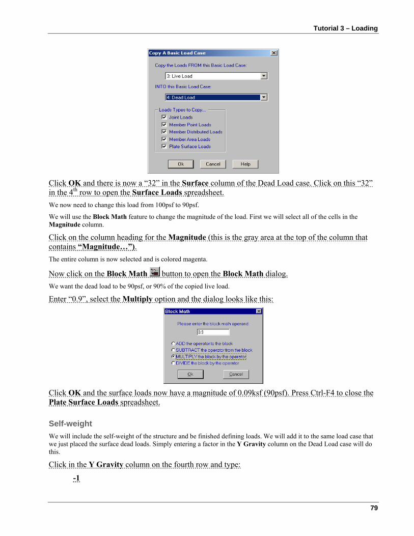
Tutorial 3 – Loading
79
Click OK and there is now a “32” in the Surface column of the Dead Load case. Click on this “32” in the 4th row to open the Surface Loads spreadsheet. We now need to change this load from 100psf to 90psf.
We will use the Block Math feature to change the magnitude of the load. First we will select all of the cells in the Magnitude column.
Click on the column heading for the Magnitude (this is the gray area at the top of the column that contains “Magnitude…”). The entire column is now selected and is colored magenta.
Now click on the Block Math button to open the Block Math dialog. We want the dead load to be 90psf, or 90% of the copied live load.
Enter “0.9”, select the Multiply option and the dialog looks like this:
Click OK and the surface loads now have a magnitude of 0.09ksf (90psf). Press Ctrl-F4 to close the Plate Surface Loads spreadsheet.
Self-weight We will include the self-weight of the structure and be finished defining loads. We will add it to the same load case that we just placed the surface dead loads. Simply entering a factor in the Y Gravity column on the Dead Load case will do this.
Click in the Y Gravity column on the fourth row and type:
-1
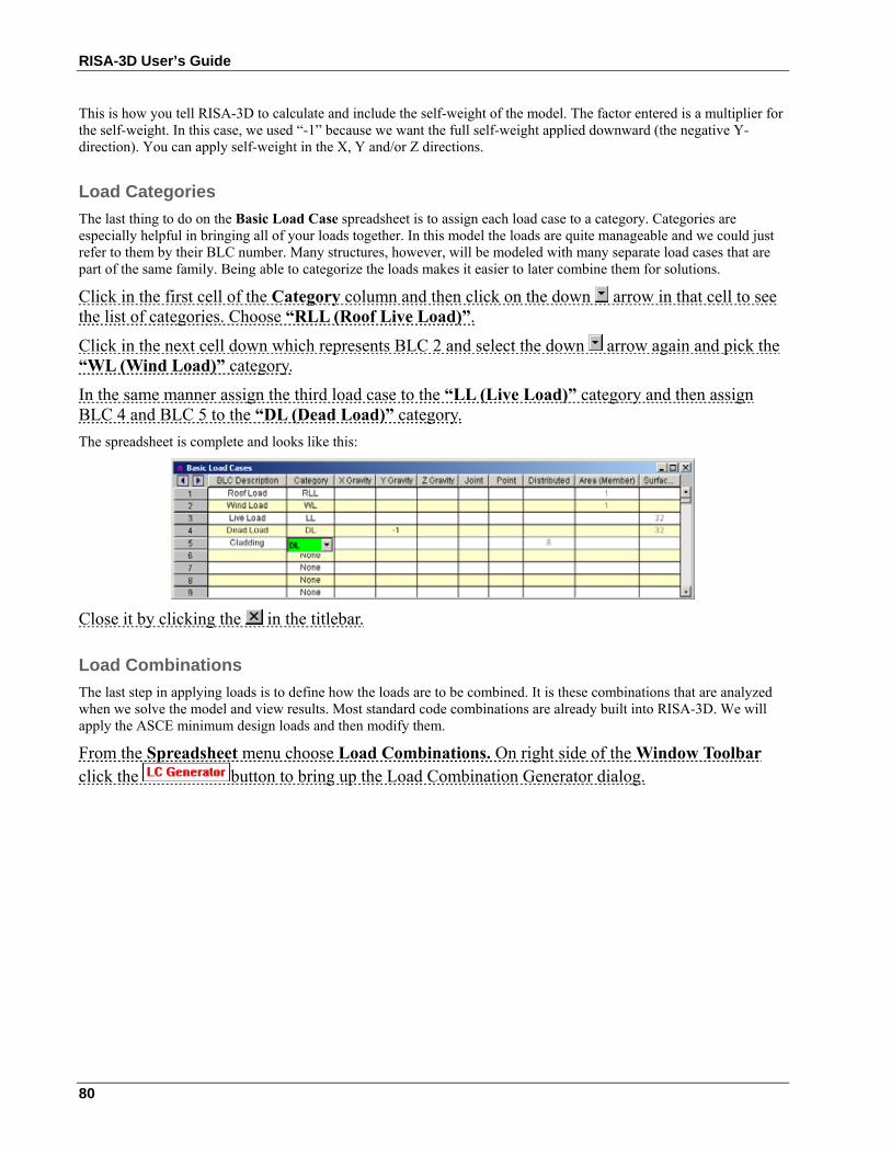
RISA-3D User’s Guide
80
This is how you tell RISA-3D to calculate and include the self-weight of the model. The factor entered is a multiplier for the self-weight. In this case, we used “-1” because we want the full self-weight applied downward (the negative Y-direction). You can apply self-weight in the X, Y and/or Z directions.
Load Categories The last thing to do on the Basic Load Case spreadsheet is to assign each load case to a category. Categories are especially helpful in bringing all of your loads together. In this model the loads are quite manageable and we could just refer to them by their BLC number. Many structures, however, will be modeled with many separate load cases that are part of the same family. Being able to categorize the loads makes it easier to later combine them for solutions.
Click in the first cell of the Category column and then click on the down arrow in that cell to see the list of categories. Choose “RLL (Roof Live Load)”.
Click in the next cell down which represents BLC 2 and select the down arrow again and pick the “WL (Wind Load)” category.
In the same manner assign the third load case to the “LL (Live Load)” category and then assign BLC 4 and BLC 5 to the “DL (Dead Load)” category. The spreadsheet is complete and looks like this:
Close it by clicking the in the titlebar.
Load Combinations The last step in applying loads is to define how the loads are to be combined. It is these combinations that are analyzed when we solve the model and view results. Most standard code combinations are already built into RISA-3D. We will apply the ASCE minimum design loads and then modify them.
From the Spreadsheet menu choose Load Combinations. On right side of the Window Toolbar click the button to bring up the Load Combination Generator dialog.
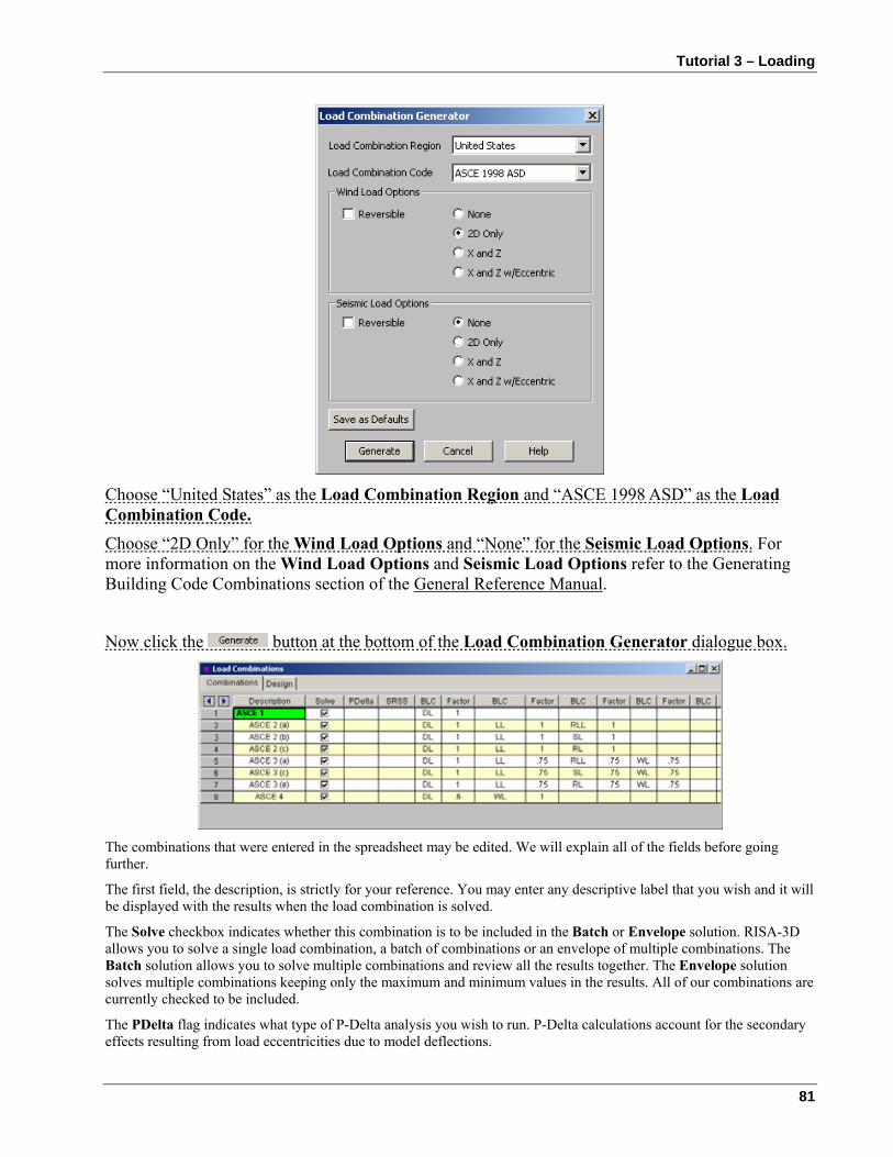
Tutorial 3 – Loading
81
Choose “United States” as the Load Combination Region and “ASCE 1998 ASD” as the Load Combination Code. Choose “2D Only” for the Wind Load Options and “None” for the Seismic Load Options. For more information on the Wind Load Options and Seismic Load Options refer to the Generating Building Code Combinations section of the General Reference Manual.
Now click the button at the bottom of the Load Combination Generator dialogue box.
The combinations that were entered in the spreadsheet may be edited. We will explain all of the fields before going further.
The first field, the description, is strictly for your reference. You may enter any descriptive label that you wish and it will be displayed with the results when the load combination is solved.
The Solve checkbox indicates whether this combination is to be included in the Batch or Envelope solution. RISA-3D allows you to solve a single load combination, a batch of combinations or an envelope of multiple combinations. The Batch solution allows you to solve multiple combinations and review all the results together. The Envelope solution solves multiple combinations keeping only the maximum and minimum values in the results. All of our combinations are currently checked to be included.
The PDelta flag indicates what type of P-Delta analysis you wish to run. P-Delta calculations account for the secondary effects resulting from load eccentricities due to model deflections.
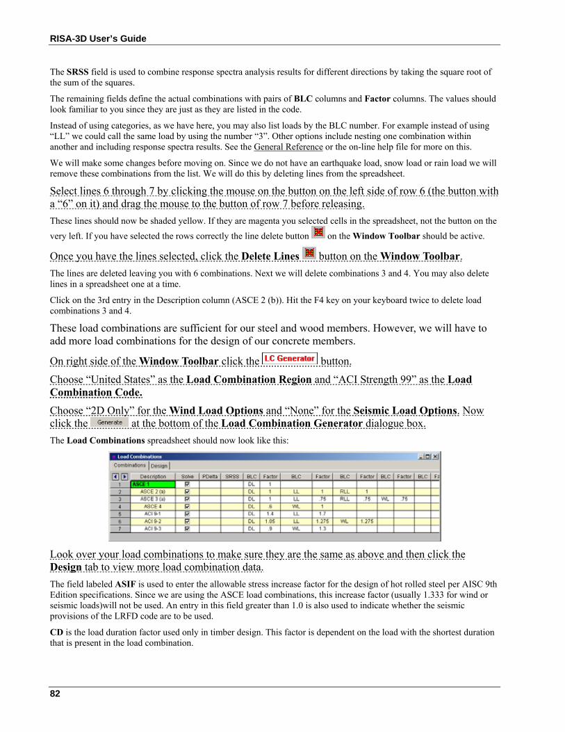
RISA-3D User’s Guide
82
The SRSS field is used to combine response spectra analysis results for different directions by taking the square root of the sum of the squares.
The remaining fields define the actual combinations with pairs of BLC columns and Factor columns. The values should look familiar to you since they are just as they are listed in the code.
Instead of using categories, as we have here, you may also list loads by the BLC number. For example instead of using “LL” we could call the same load by using the number “3”. Other options include nesting one combination within another and including response spectra results. See the General Reference or the on-line help file for more on this.
We will make some changes before moving on. Since we do not have an earthquake load, snow load or rain load we will remove these combinations from the list. We will do this by deleting lines from the spreadsheet.
Select lines 6 through 7 by clicking the mouse on the button on the left side of row 6 (the button with a “6” on it) and drag the mouse to the button of row 7 before releasing. These lines should now be shaded yellow. If they are magenta you selected cells in the spreadsheet, not the button on the very left. If you have selected the rows correctly the line delete button on the Window Toolbar should be active.
Once you have the lines selected, click the Delete Lines button on the Window Toolbar. The lines are deleted leaving you with 6 combinations. Next we will delete combinations 3 and 4. You may also delete lines in a spreadsheet one at a time.
Click on the 3rd entry in the Description column (ASCE 2 (b)). Hit the F4 key on your keyboard twice to delete load combinations 3 and 4.
These load combinations are sufficient for our steel and wood members. However, we will have to add more load combinations for the design of our concrete members.
On right side of the Window Toolbar click the button.
Choose “United States” as the Load Combination Region and “ACI Strength 99” as the Load Combination Code. Choose “2D Only” for the Wind Load Options and “None” for the Seismic Load Options. Now click the at the bottom of the Load Combination Generator dialogue box. The Load Combinations spreadsheet should now look like this:
Look over your load combinations to make sure they are the same as above and then click the Design tab to view more load combination data. The field labeled ASIF is used to enter the allowable stress increase factor for the design of hot rolled steel per AISC 9th Edition specifications. Since we are using the ASCE load combinations, this increase factor (usually 1.333 for wind or seismic loads)will not be used. An entry in this field greater than 1.0 is also used to indicate whether the seismic provisions of the LRFD code are to be used.
CD is the load duration factor used only in timber design. This factor is dependent on the load with the shortest duration that is present in the load combination.
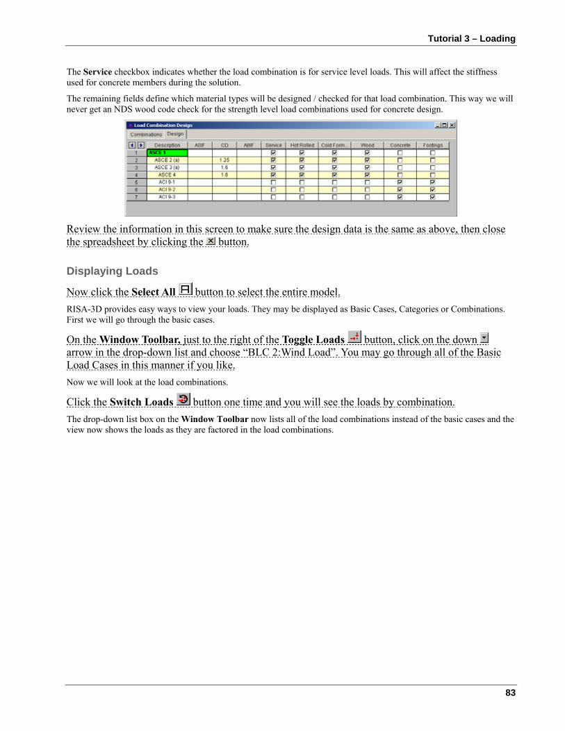
Tutorial 3 – Loading
83
The Service checkbox indicates whether the load combination is for service level loads. This will affect the stiffness used for concrete members during the solution.
The remaining fields define which material types will be designed / checked for that load combination. This way we will never get an NDS wood code check for the strength level load combinations used for concrete design.
Review the information in this screen to make sure the design data is the same as above, then close the spreadsheet by clicking the button.
Displaying Loads
Now click the Select All button to select the entire model. RISA-3D provides easy ways to view your loads. They may be displayed as Basic Cases, Categories or Combinations. First we will go through the basic cases.
On the Window Toolbar, just to the right of the Toggle Loads button, click on the down arrow in the drop-down list and choose “BLC 2:Wind Load”. You may go through all of the Basic Load Cases in this manner if you like. Now we will look at the load combinations.
Click the Switch Loads button one time and you will see the loads by combination. The drop-down list box on the Window Toolbar now lists all of the load combinations instead of the basic cases and the view now shows the loads as they are factored in the load combinations.
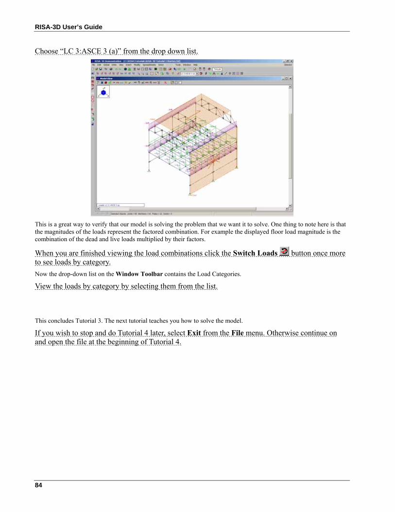
RISA-3D User’s Guide
84
Choose “LC 3:ASCE 3 (a)” from the drop down list.
This is a great way to verify that our model is solving the problem that we want it to solve. One thing to note here is that the magnitudes of the loads represent the factored combination. For example the displayed floor load magnitude is the combination of the dead and live loads multiplied by their factors.
When you are finished viewing the load combinations click the Switch Loads button once more to see loads by category. Now the drop-down list on the Window Toolbar contains the Load Categories.
View the loads by category by selecting them from the list.
This concludes Tutorial 3. The next tutorial teaches you how to solve the model.
If you wish to stop and do Tutorial 4 later, select Exit from the File menu. Otherwise continue on and open the file at the beginning of Tutorial 4.
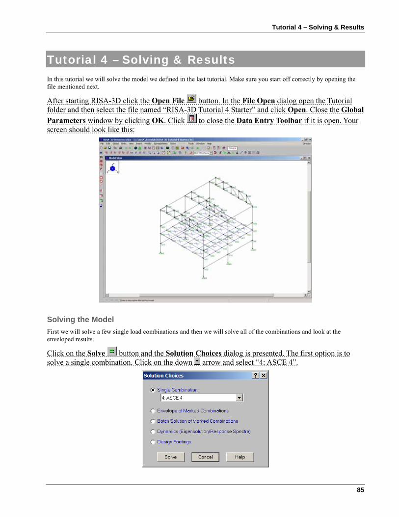
Tutorial 4 – Solving & Results
85
Tutorial 4 – Solving & Results In this tutorial we will solve the model we defined in the last tutorial. Make sure you start off correctly by opening the file mentioned next.
After starting RISA-3D click the Open File button. In the File Open dialog open the Tutorial folder and then select the file named “RISA-3D Tutorial 4 Starter” and click Open. Close the Global Parameters window by clicking OK. Click to close the Data Entry Toolbar if it is open. Your screen should look like this:
Solving the Model First we will solve a few single load combinations and then we will solve all of the combinations and look at the enveloped results.
Click on the Solve button and the Solution Choices dialog is presented. The first option is to solve a single combination. Click on the down arrow and select “4: ASCE 4”.
RISA-3D User’s Guide
86
Click Solve. RISA-3D reports the solution steps as they occur. When the solution is complete, you are presented with the Joint Reactions spreadsheet. You will notice that the reactions are summed at the bottom of the spreadsheet. The center of gravity of the vertical loads is reported in the last row. The Results toolbar is also opened for access to other results. You may view results in the spreadsheets, plotted on the model in the view, or in detail for each member. We will cover these three options next.
Viewing and Sorting Results Spreadsheets You may access the result spreadsheets from the Results menu or from the Results Toolbar which is placed on the right side after the solution is performed. Let's use the toolbar to quickly review the results. You may use the Topic Help and Help buttons for a more detailed explanation of the results. You may also look to the status bar for an explanation of the active cell. Take a moment to look over each spreadsheet. Use the scroll bars to view information not displayed in the window.
To review the results, you can page up and down or scroll up and down a line at a time. [Home] and [End] take you to the top and bottom of the results. You can use the Find feature to locate specific results and the Sort feature to sort the results. The Exclude feature allows you to hide results that are not of interest. For now just note what results are available, in the next section we’ll discuss how to quickly manipulate them.
Select from the Results Toolbar to review these results.
Now select to view the forces which are listed for 7 locations on each member. This is because we specified 7 sections back on the Global settings. Remember you can sort the spreadsheets. We will use the Sort feature to sort the strong axis moment results.
Click in any cell in the last column, which is the z-z Moment column. Now click the Sort button on the Window Toolbar to access the sorting options. Select “Abs Max to AbsMin” and click OK. You'll be returned to the Forces spreadsheet with the members sorted according to their absolute maximum z-axis bending moment value.
Select to view the member stresses.
Select to view the torsional stresses, including warping normal and shear stresses for the members that warp.
Select to view the member deflections. This spreadsheet also shows the deflections as a ratio of member length (the “L/y” ratios) providing an easy check against deflection criteria such as “L/360”.
Select to view the suggested redesign shapes (we'll use these later).
Select and choose the Hot Rolled tab. Here we have the AISC code checks, i.e. ratio of actual to allowable stresses, per ASD 9th Edition criteria. Failing members would be highlighted with red text. The allowable stresses, Cb and Cm values and controlling equation are listed. If we were doing LRFD based design, we would see the member strengths listed here (along with the code check value).
Select the Cold Formed tab to view the cold formed steel code checks. The design strengths Pn, Mny, & Mnz are listed along with the code check values and controlling equation. Factored design stresses and controlling equation are also listed.
Select the Wood tab to view the wood code checks for our wood truss members.
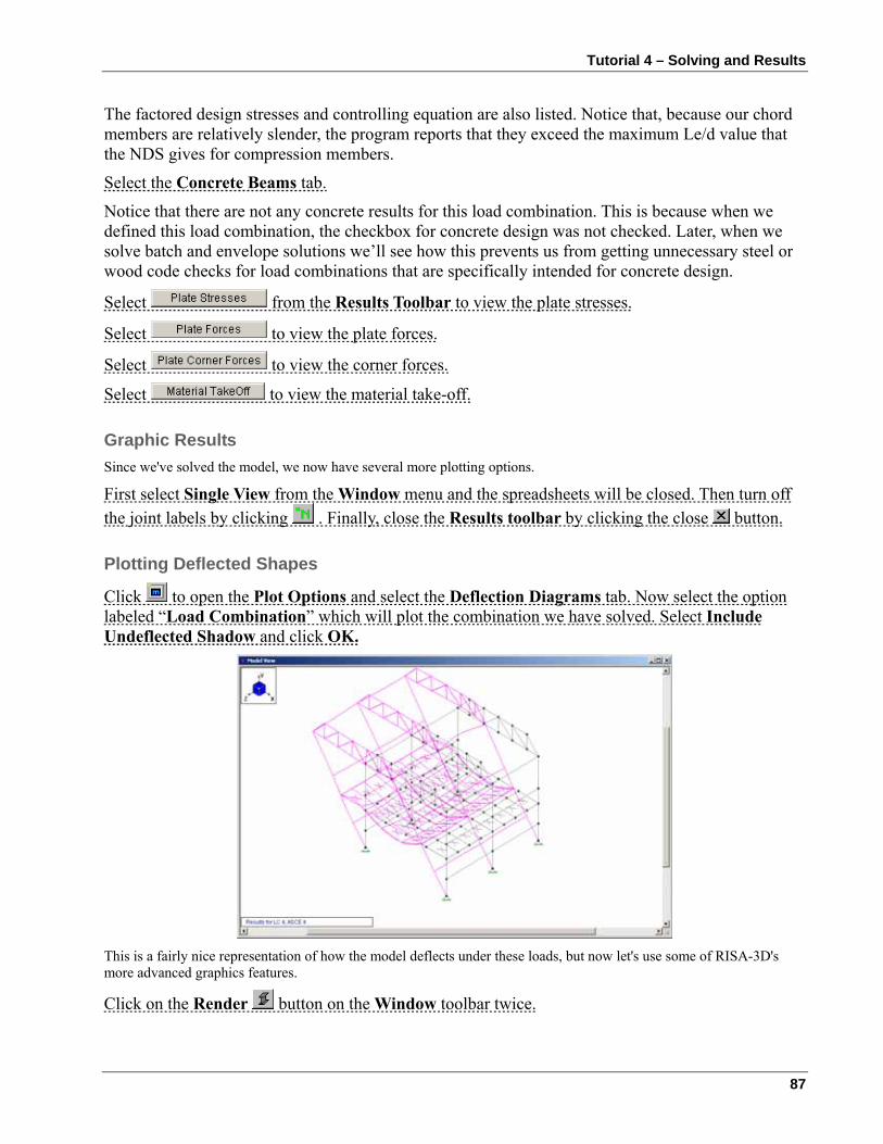
Tutorial 4 – Solving and Results
87
The factored design stresses and controlling equation are also listed. Notice that, because our chord members are relatively slender, the program reports that they exceed the maximum Le/d value that the NDS gives for compression members.
Select the Concrete Beams tab.
Notice that there are not any concrete results for this load combination. This is because when we defined this load combination, the checkbox for concrete design was not checked. Later, when we solve batch and envelope solutions we’ll see how this prevents us from getting unnecessary steel or wood code checks for load combinations that are specifically intended for concrete design.
Select from the Results Toolbar to view the plate stresses.
Select to view the plate forces.
Select to view the corner forces.
Select to view the material take-off.
Graphic Results Since we've solved the model, we now have several more plotting options.
First select Single View from the Window menu and the spreadsheets will be closed. Then turn off the joint labels by clicking . Finally, close the Results toolbar by clicking the close button.
Plotting Deflected Shapes
Click to open the Plot Options and select the Deflection Diagrams tab. Now select the option labeled “Load Combination” which will plot the combination we have solved. Select Include Undeflected Shadow and click OK.
This is a fairly nice representation of how the model deflects under these loads, but now let's use some of RISA-3D's more advanced graphics features.
Click on the Render button on the Window toolbar twice.
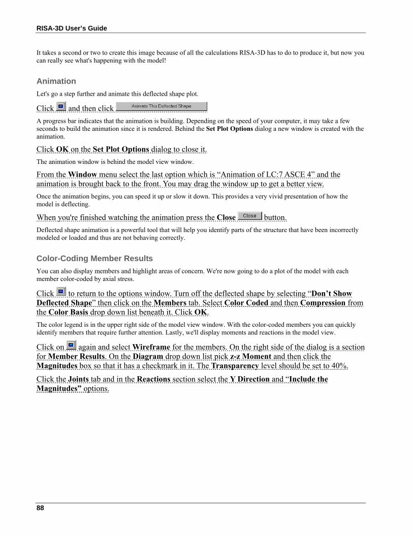
RISA-3D User’s Guide
88
It takes a second or two to create this image because of all the calculations RISA-3D has to do to produce it, but now you can really see what's happening with the model!
Animation Let's go a step further and animate this deflected shape plot.
Click and then click A progress bar indicates that the animation is building. Depending on the speed of your computer, it may take a few seconds to build the animation since it is rendered. Behind the Set Plot Options dialog a new window is created with the animation.
Click OK on the Set Plot Options dialog to close it. The animation window is behind the model view window.
From the Window menu select the last option which is “Animation of LC:7 ASCE 4” and the animation is brought back to the front. You may drag the window up to get a better view. Once the animation begins, you can speed it up or slow it down. This provides a very vivid presentation of how the model is deflecting.
When you're finished watching the animation press the Close button. Deflected shape animation is a powerful tool that will help you identify parts of the structure that have been incorrectly modeled or loaded and thus are not behaving correctly.
Color-Coding Member Results You can also display members and highlight areas of concern. We're now going to do a plot of the model with each member color-coded by axial stress.
Click to return to the options window. Turn off the deflected shape by selecting “Don’t Show Deflected Shape” then click on the Members tab. Select Color Coded and then Compression from the Color Basis drop down list beneath it. Click OK. The color legend is in the upper right side of the model view window. With the color-coded members you can quickly identify members that require further attention. Lastly, we'll display moments and reactions in the model view.
Click on again and select Wireframe for the members. On the right side of the dialog is a section for Member Results. On the Diagram drop down list pick z-z Moment and then click the Magnitudes box so that it has a checkmark in it. The Transparency level should be set to 40%.
Click the Joints tab and in the Reactions section select the Y Direction and “Include the Magnitudes” options.
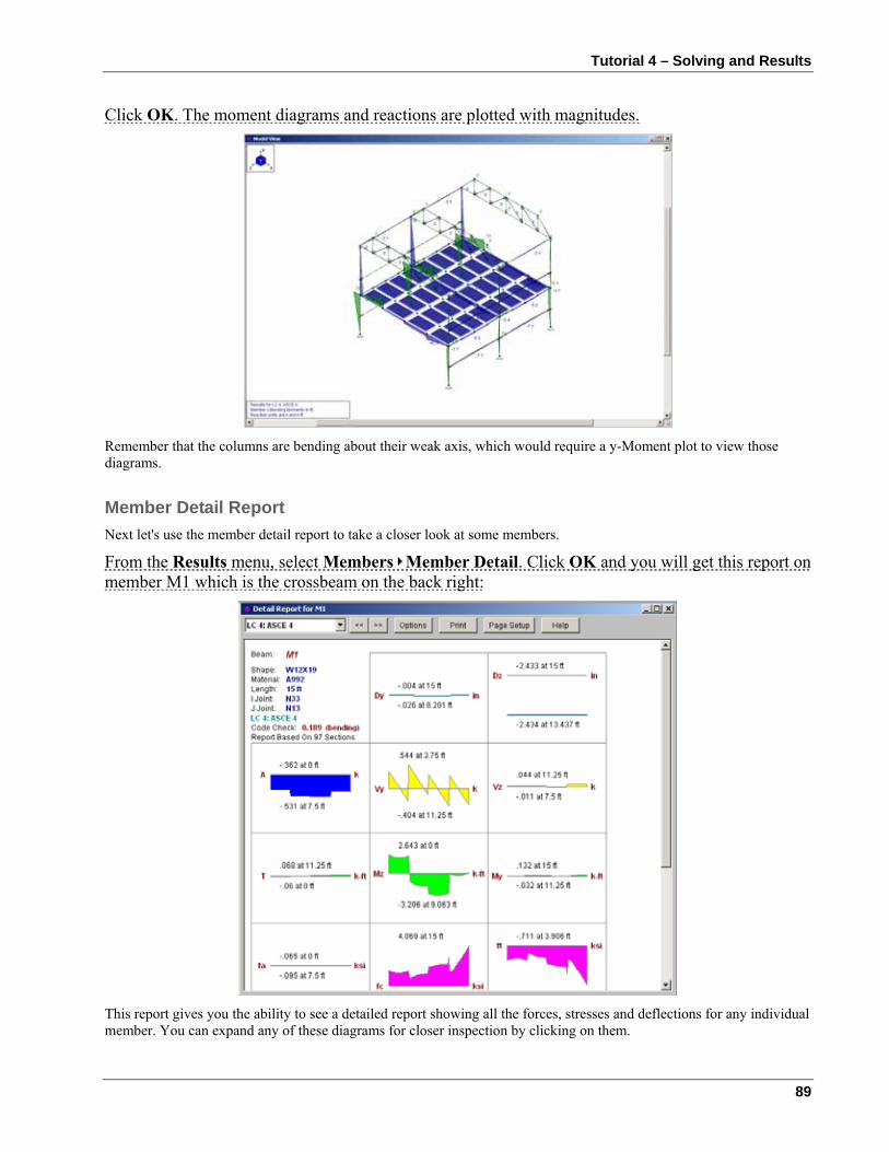
Tutorial 4 – Solving and Results
89
Click OK. The moment diagrams and reactions are plotted with magnitudes.
Remember that the columns are bending about their weak axis, which would require a y-Moment plot to view those diagrams.
Member Detail Report Next let's use the member detail report to take a closer look at some members.
From the Results menu, select Members Member Detail. Click OK and you will get this report on member M1 which is the crossbeam on the back right:
This report gives you the ability to see a detailed report showing all the forces, stresses and deflections for any individual member. You can expand any of these diagrams for closer inspection by clicking on them.
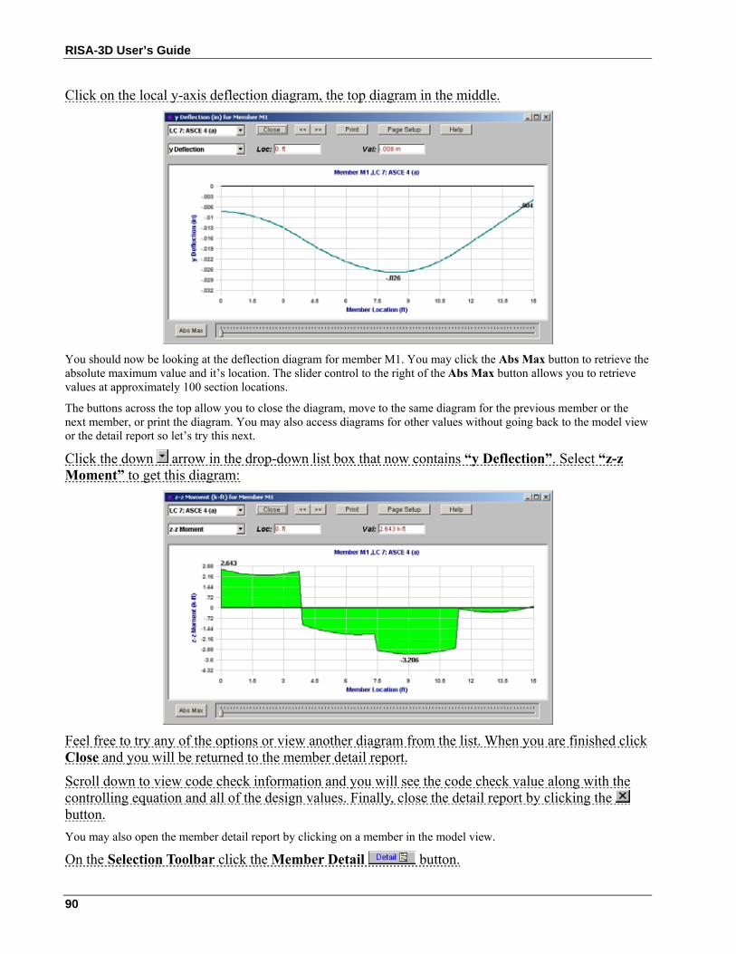
RISA-3D User’s Guide
90
Click on the local y-axis deflection diagram, the top diagram in the middle.
You should now be looking at the deflection diagram for member M1. You may click the Abs Max button to retrieve the absolute maximum value and it’s location. The slider control to the right of the Abs Max button allows you to retrieve values at approximately 100 section locations.
The buttons across the top allow you to close the diagram, move to the same diagram for the previous member or the next member, or print the diagram. You may also access diagrams for other values without going back to the model view or the detail report so let’s try this next.
Click the down arrow in the drop-down list box that now contains “y Deflection”. Select “z-z Moment” to get this diagram:
Feel free to try any of the options or view another diagram from the list. When you are finished click Close and you will be returned to the member detail report.
Scroll down to view code check information and you will see the code check value along with the controlling equation and all of the design values. Finally, close the detail report by clicking the button. You may also open the member detail report by clicking on a member in the model view.
On the Selection Toolbar click the Member Detail button.
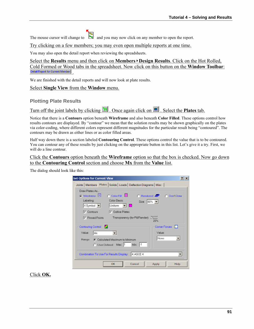
Tutorial 4 – Solving and Results
91
The mouse cursor will change to and you may now click on any member to open the report.
Try clicking on a few members; you may even open multiple reports at one time. You may also open the detail report when reviewing the spreadsheets.
Select the Results menu and then click on Members Design Results. Click on the Hot Rolled, Cold Formed or Wood tabs in the spreadsheet. Now click on this button on the Window Toolbar:
. We are finished with the detail reports and will now look at plate results.
Select Single View from the Window menu.
Plotting Plate Results
Turn off the joint labels by clicking . Once again click on . Select the Plates tab. Notice that there is a Contours option beneath Wireframe and also beneath Color Filled. These options control how results contours are displayed. By “contour” we mean that the solution results may be shown graphically on the plates via color-coding, where different colors represent different magnitudes for the particular result being “contoured”. The contours may be drawn as either lines or as color filled areas.
Half way down there is a section labeled Contouring Control. These options control the value that is to be contoured. You can contour any of these results by just clicking on the appropriate button in this list. Let’s give it a try. First, we will do a line contour.
Click the Contours option beneath the Wireframe option so that the box is checked. Now go down to the Contouring Control section and choose Mx from the Value list. The dialog should look like this:
Click OK.
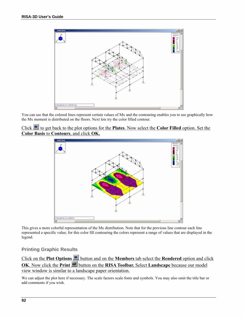
RISA-3D User’s Guide
92
You can see that the colored lines represent certain values of Mx and the contouring enables you to see graphically how the Mx moment is distributed on the floors. Next lets try the color filled contour.
Click to get back to the plot options for the Plates. Now select the Color Filled option. Set the Color Basis to Contours, and click OK.
This gives a more colorful representation of the Mx distribution. Note that for the previous line contour each line represented a specific value; for this color fill contouring the colors represent a range of values that are displayed in the legend.
Printing Graphic Results
Click on the Plot Options button and on the Members tab select the Rendered option and click OK. Now click the Print button on the RISA Toolbar. Select Landscape because our model view window is similar to a landscape paper orientation. We can adjust the plot here if necessary. The scale factors scale fonts and symbols. You may also omit the title bar or add comments if you wish.
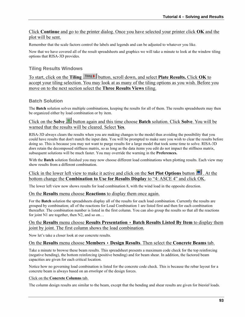
Tutorial 4 – Solving and Results
93
Click Continue and go to the printer dialog. Once you have selected your printer click OK and the plot will be sent. Remember that the scale factors control the labels and legends and can be adjusted to whatever you like.
Now that we have covered all of the result spreadsheets and graphics we will take a minute to look at the window tiling options that RISA-3D provides.
Tiling Results Windows
To start, click on the Tiling button, scroll down, and select Plate Results. Click OK to accept your tiling selection. You may look at as many of the tiling options as you wish. Before you move on to the next section select the Three Results Views tiling.
Batch Solution The Batch solution solves multiple combinations, keeping the results for all of them. The results spreadsheets may then be organized either by load combination or by item.
Click on the Solve button again and this time choose Batch solution. Click Solve. You will be warned that the results will be cleared. Select Yes. RISA-3D always clears the results when you are making changes to the model thus avoiding the possibility that you could have results that don't match the input data. You will be prompted to make sure you wish to clear the results before doing so. This is because you may not want to purge results for a large model that took some time to solve. RISA-3D does retain the decomposed stiffness matrix, so as long as the data items you edit do not impact the stiffness matrix, subsequent solutions will be much faster. You may override the warning in the Preferences.
With the Batch solution finished you may now choose different load combinations when plotting results. Each view may show results from a different combination.
Click in the lower left view to make it active and click on the Set Plot Options button . At the bottom change the Combination to Use for Results Display to “4: ASCE 4” and click OK. The lower left view now shows results for load combination 8, with the wind load in the opposite direction.
On the Results menu choose Reactions to display them once again. For the Batch solution the spreadsheets display all of the results for each load combination. Currently the results are grouped by combination; all of the reactions for Load Combination 1 are listed first and then for each combination thereafter. The combination number is listed in the first column. You can also group the results so that all the reactions for joint N1 are together, then N2, and so on…
On the Results menu choose Results Presentation Batch Results Listed By Item to display them joint by joint. The first column shows the load combination. Now let’s take a closer look at our concrete results.
On the Results menu choose Members Design Results. Then select the Concrete Beams tab. Take a minute to browse these beam results. This spreadsheet presents a maximum code check for the top reinforcing (negative bending), the bottom reinforcing (positive bending) and for beam shear. In addition, the factored beam capacities are given for each critical location.
Notice how no governing load combination is listed for the concrete code check. This is because the rebar layout for a concrete beam is always based on an envelope of the design forces.
Click on the Concrete Columns tab.
The column design results are similar to the beam, except that the bending and shear results are given for biaxial loads.
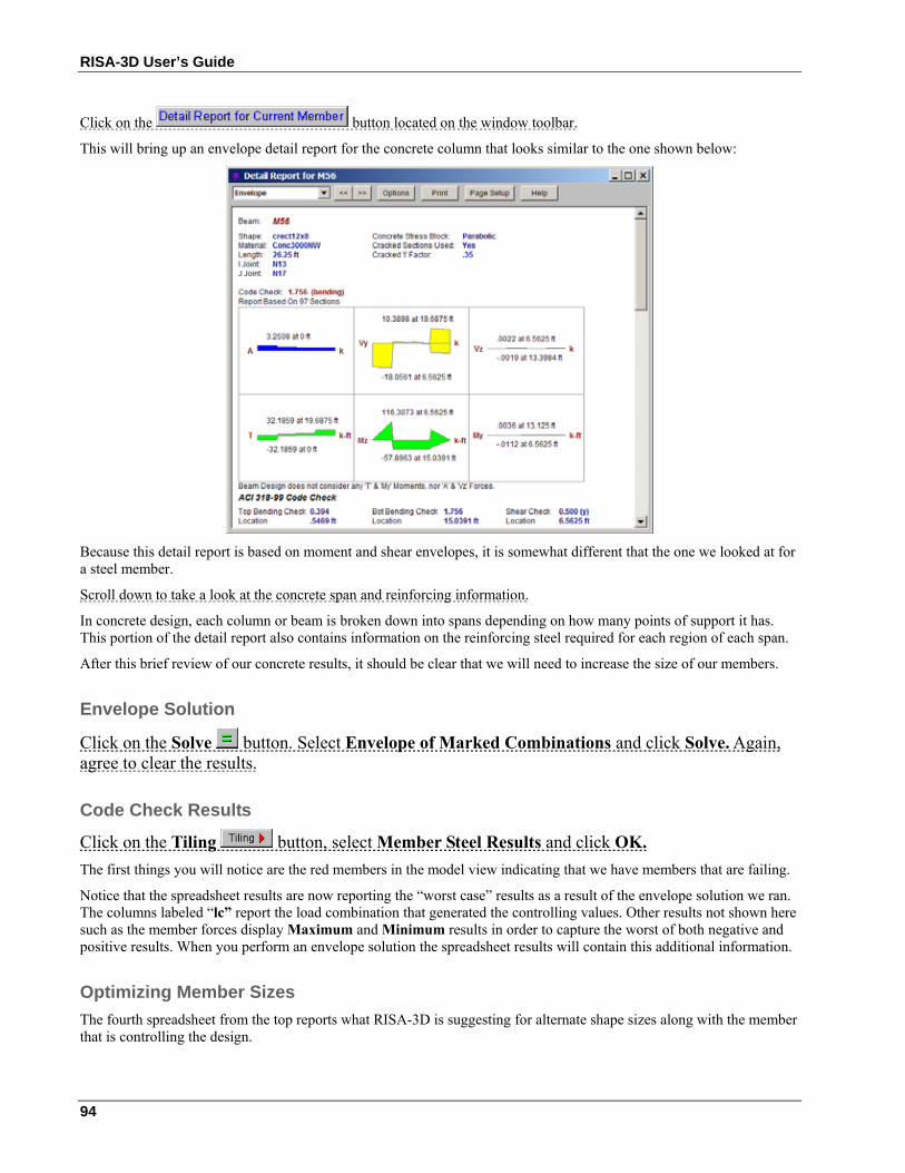
RISA-3D User’s Guide
94
Click on the button located on the window toolbar.
This will bring up an envelope detail report for the concrete column that looks similar to the one shown below:
Because this detail report is based on moment and shear envelopes, it is somewhat different that the one we looked at for a steel member.
Scroll down to take a look at the concrete span and reinforcing information.
In concrete design, each column or beam is broken down into spans depending on how many points of support it has. This portion of the detail report also contains information on the reinforcing steel required for each region of each span.
After this brief review of our concrete results, it should be clear that we will need to increase the size of our members.
Envelope Solution
Click on the Solve button. Select Envelope of Marked Combinations and click Solve. Again, agree to clear the results.
Code Check Results
Click on the Tiling button, select Member Steel Results and click OK. The first things you will notice are the red members in the model view indicating that we have members that are failing.
Notice that the spreadsheet results are now reporting the “worst case” results as a result of the envelope solution we ran. The columns labeled “lc” report the load combination that generated the controlling values. Other results not shown here such as the member forces display Maximum and Minimum results in order to capture the worst of both negative and positive results. When you perform an envelope solution the spreadsheet results will contain this additional information.
Optimizing Member Sizes The fourth spreadsheet from the top reports what RISA-3D is suggesting for alternate shape sizes along with the member that is controlling the design.
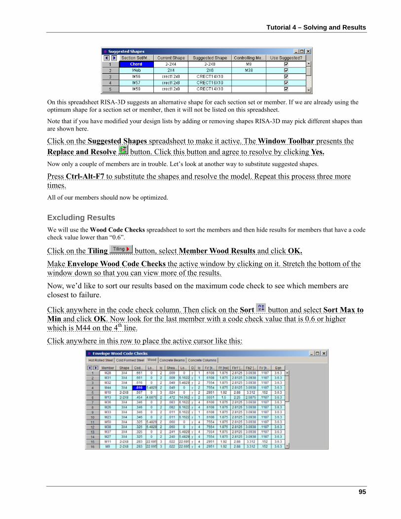
Tutorial 4 – Solving and Results
95
On this spreadsheet RISA-3D suggests an alternative shape for each section set or member. If we are already using the optimum shape for a section set or member, then it will not be listed on this spreadsheet.
Note that if you have modified your design lists by adding or removing shapes RISA-3D may pick different shapes than are shown here.
Click on the Suggested Shapes spreadsheet to make it active. The Window Toolbar presents the Replace and Resolve button. Click this button and agree to resolve by clicking Yes. Now only a couple of members are in trouble. Let’s look at another way to substitute suggested shapes.
Press Ctrl-Alt-F7 to substitute the shapes and resolve the model. Repeat this process three more times. All of our members should now be optimized.
Excluding Results We will use the Wood Code Checks spreadsheet to sort the members and then hide results for members that have a code check value lower than “0.6”.
Click on the Tiling button, select Member Wood Results and click OK.
Make Envelope Wood Code Checks the active window by clicking on it. Stretch the bottom of the window down so that you can view more of the results.
Now, we’d like to sort our results based on the maximum code check to see which members are closest to failure.
Click anywhere in the code check column. Then click on the Sort button and select Sort Max to Min and click OK. Now look for the last member with a code check value that is 0.6 or higher which is M44 on the 4th line.
Click anywhere in this row to place the active cursor like this:
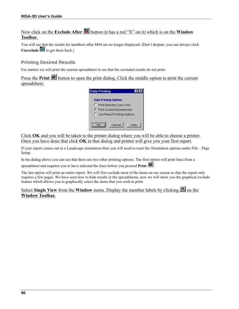
RISA-3D User’s Guide
96
Now click on the Exclude After button (it has a red “X” on it) which is on the Window Toolbar. You will see that the results for members after M44 are no longer displayed. (Don’t despair, you can always click Unexclude to get them back.)
Printing Desired Results For starters we will print the current spreadsheet to see that the excluded results do not print.
Press the Print button to open the print dialog. Click the middle option to print the current spreadsheet.
Click OK and you will be taken to the printer dialog where you will be able to choose a printer. Once you have done that click OK in that dialog and printer will give you your first report. If your report comes out in a Landscape orientation then you will need to reset the Orientation options under File – Page Setup.
In the dialog above you can see that there are two other printing options. The first option will print lines from a spreadsheet and requires you to have selected the lines before you pressed Print .
The last option will print an entire report. We will first exclude most of the items on our screen so that the report only requires a few pages. We have seen how to hide results in the spreadsheets, now we will show you the graphical exclude feature which allows you to graphically select the items that you wish to print.
Select Single View from the Window menu. Display the member labels by clicking on the Window Toolbar.
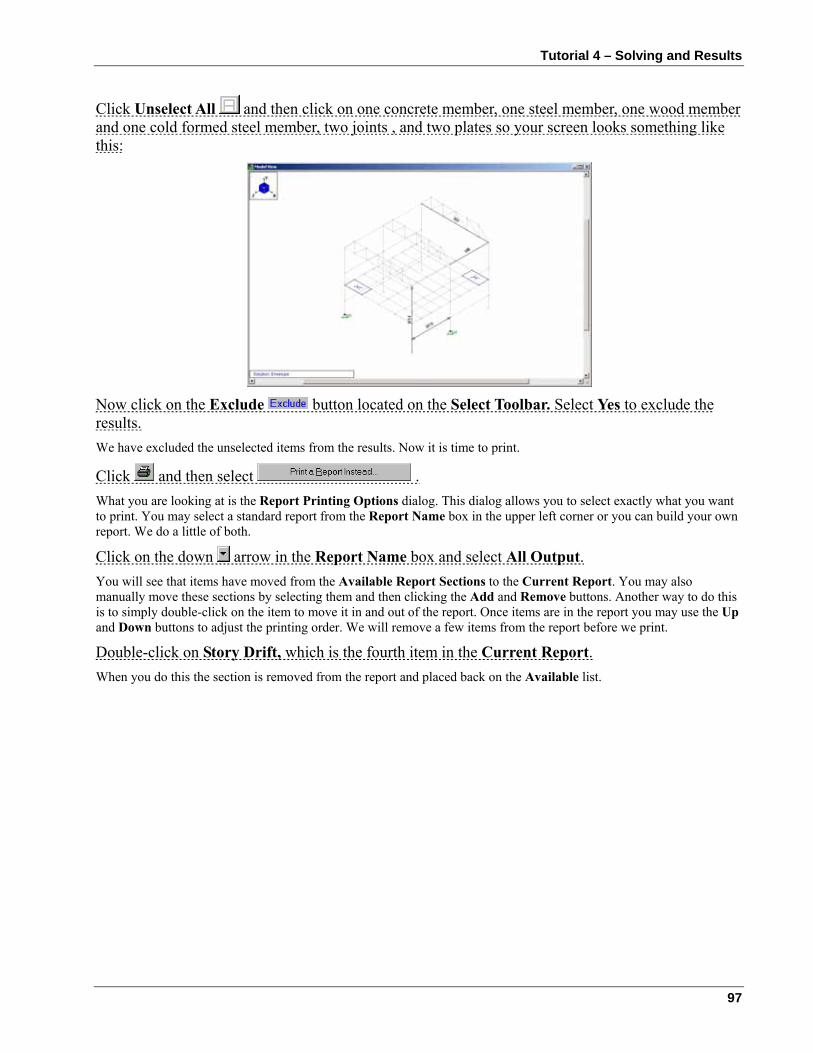
Tutorial 4 – Solving and Results
97
Click Unselect All and then click on one concrete member, one steel member, one wood member and one cold formed steel member, two joints , and two plates so your screen looks something like this:
Now click on the Exclude button located on the Select Toolbar. Select Yes to exclude the results. We have excluded the unselected items from the results. Now it is time to print.
Click and then select . What you are looking at is the Report Printing Options dialog. This dialog allows you to select exactly what you want to print. You may select a standard report from the Report Name box in the upper left corner or you can build your own report. We do a little of both.
Click on the down arrow in the Report Name box and select All Output. You will see that items have moved from the Available Report Sections to the Current Report. You may also manually move these sections by selecting them and then clicking the Add and Remove buttons. Another way to do this is to simply double-click on the item to move it in and out of the report. Once items are in the report you may use the Up and Down buttons to adjust the printing order. We will remove a few items from the report before we print.
Double-click on Story Drift, which is the fourth item in the Current Report. When you do this the section is removed from the report and placed back on the Available list.
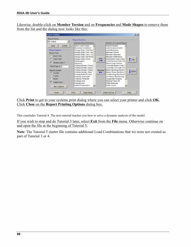
RISA-3D User’s Guide
98
Likewise, double-click on Member Torsion and on Frequencies and Mode Shapes to remove them from the list and the dialog now looks like this:
Click Print to get to your systems print dialog where you can select your printer and click OK. Click Close on the Report Printing Options dialog box.
This concludes Tutorial 4. The next tutorial teaches you how to solve a dynamic analysis of the model.
If you wish to stop and do Tutorial 5 later, select Exit from the File menu. Otherwise continue on and open the file at the beginning of Tutorial 5.
Note: The Tutorial 5 starter file contains additional Load Combinations that we were not created as part of Tutorial 3 or 4.
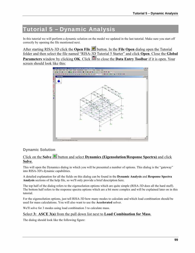
Tutorial 5 – Dynamic Analysis
99
Tutorial 5 – Dynamic Analysis In this tutorial we will perform a dynamic solution on the model we updated in the last tutorial. Make sure you start off correctly by opening the file mentioned next.
After starting RISA-3D click the Open File button. In the File Open dialog open the Tutorial folder and then select the file named “RISA-3D Tutorial 5 Starter” and click Open. Close the Global Parameters window by clicking OK. Click to close the Data Entry Toolbar if it is open. Your screen should look like this:
Dynamic Solution
Click on the Solve button and select Dynamics (Eigensolution/Response Spectra) and click Solve. This will open the Dynamics dialog in which you will be presented a number of options. This dialog is the “gateway” into RISA-3D's dynamic capabilities.
A detailed explanation for all the fields on this dialog can be found in the Dynamic Analysis and Response Spectra Analysis sections of the help file, so we'll only provide a brief description here.
The top half of the dialog refers to the eigensolution options which are quite simple (RISA-3D does all the hard stuff). The bottom half refers to the response spectra options which are a bit more complex and will be explained later on in this tutorial.
For the eigensolution options, just tell RISA-3D how many modes to calculate and which load combination should be used for mass calculations. You will also want to use the Accelerated solver.
We'll solve for 3 modes using load combination 3 to calculate mass.
Select 3: ASCE 3(a) from the pull down list next to Load Combination for Mass. The dialog should look like the following figure:
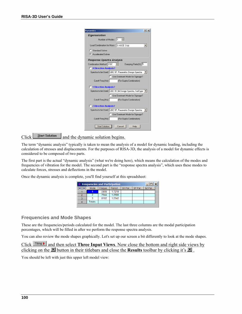
RISA-3D User’s Guide
100
Click and the dynamic solution begins. The term “dynamic analysis” typically is taken to mean the analysis of a model for dynamic loading, including the calculation of stresses and displacements. For the purposes of RISA-3D, the analysis of a model for dynamic effects is considered to be composed of two parts.
The first part is the actual “dynamic analysis” (what we're doing here), which means the calculation of the modes and frequencies of vibration for the model. The second part is the “response spectra analysis”, which uses these modes to calculate forces, stresses and deflections in the model.
Once the dynamic analysis is complete, you'll find yourself at this spreadsheet:
Frequencies and Mode Shapes These are the frequencies/periods calculated for the model. The last three columns are the modal participation percentages, which will be filled in after we perform the response spectra analysis.
You can also review the mode shapes graphically. Let's set up our screen a bit differently to look at the mode shapes.
Click and then select Three Input Views. Now close the bottom and right side views by clicking on the button in their titlebars and close the Results toolbar by clicking it’s . You should be left with just this upper left model view:
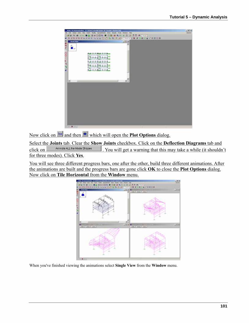
Tutorial 5 – Dynamic Analysis
101
Now click on and then which will open the Plot Options dialog.
Select the Joints tab. Clear the Show Joints checkbox. Click on the Deflection Diagrams tab and click on . You will get a warning that this may take a while (it shouldn’t for three modes). Click Yes.
You will see three different progress bars, one after the other, build three different animations. After the animations are built and the progress bars are gone click OK to close the Plot Options dialog. Now click on Tile Horizontal from the Window menu.
When you've finished viewing the animations select Single View from the Window menu.
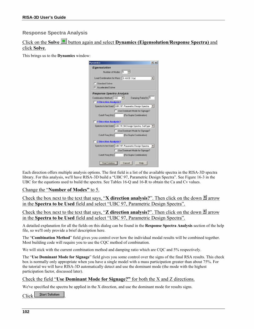
RISA-3D User’s Guide
102
Response Spectra Analysis
Click on the Solve button again and select Dynamics (Eigensolution/Response Spectra) and click Solve. This brings us to the Dynamics window:
Each direction offers multiple analysis options. The first field is a list of the available spectra in the RISA-3D spectra library. For this analysis, we'll have RISA-3D build a “UBC 97, Parametric Design Spectra”. See Figure 16-3 in the UBC for the equations used to build the spectra. See Tables 16-Q and 16-R to obtain the Ca and Cv values.
Change the “Number of Modes” to 5.
Check the box next to the text that says, “X direction analysis?”. Then click on the down arrow in the Spectra to be Used field and select “UBC 97, Parametric Design Spectra”.
Check the box next to the text that says, “Z direction analysis?”. Then click on the down arrow in the Spectra to be Used field and select “UBC 97, Parametric Design Spectra”. A detailed explanation for all the fields on this dialog can be found in the Response Spectra Analysis section of the help file, so we'll only provide a brief description here.
The “Combination Method” field gives you control over how the individual modal results will be combined together. Most building code will require you to use the CQC method of combination.
We will stick with the current combination method and damping ratio which are CQC and 5% respectively.
The “Use Dominant Mode for Signage” field gives you some control over the signs of the final RSA results. This check box is normally only appropriate when you have a single model with a mass participation greater than about 75%. For the tutorial we will have RISA-3D automatically detect and use the dominant mode (the mode with the highest participation factor, discussed later).
Check the field “Use Dominant Mode for Signage?” for both the X and Z directions. We've specified the spectra be applied in the X direction, and use the dominant mode for results signs.
Click .
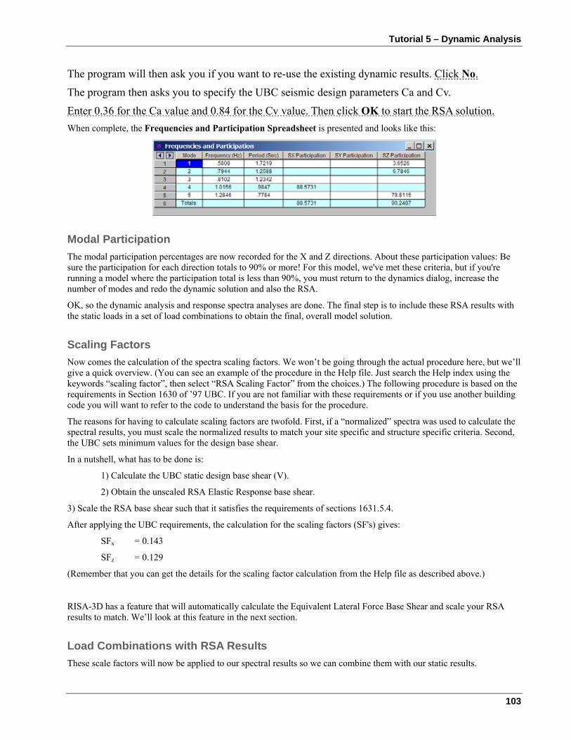
Tutorial 5 – Dynamic Analysis
103
The program will then ask you if you want to re-use the existing dynamic results. Click No.
The program then asks you to specify the UBC seismic design parameters Ca and Cv.
Enter 0.36 for the Ca value and 0.84 for the Cv value. Then click OK to start the RSA solution. When complete, the Frequencies and Participation Spreadsheet is presented and looks like this:
Modal Participation The modal participation percentages are now recorded for the X and Z directions. About these participation values: Be sure the participation for each direction totals to 90% or more! For this model, we've met these criteria, but if you're running a model where the participation total is less than 90%, you must return to the dynamics dialog, increase the number of modes and redo the dynamic solution and also the RSA.
OK, so the dynamic analysis and response spectra analyses are done. The final step is to include these RSA results with the static loads in a set of load combinations to obtain the final, overall model solution.
Scaling Factors Now comes the calculation of the spectra scaling factors. We won’t be going through the actual procedure here, but we’ll give a quick overview. (You can see an example of the procedure in the Help file. Just search the Help index using the keywords “scaling factor”, then select “RSA Scaling Factor” from the choices.) The following procedure is based on the requirements in Section 1630 of ’97 UBC. If you are not familiar with these requirements or if you use another building code you will want to refer to the code to understand the basis for the procedure.
The reasons for having to calculate scaling factors are twofold. First, if a “normalized” spectra was used to calculate the spectral results, you must scale the normalized results to match your site specific and structure specific criteria. Second, the UBC sets minimum values for the design base shear.
In a nutshell, what has to be done is:
1) Calculate the UBC static design base shear (V).
2) Obtain the unscaled RSA Elastic Response base shear.
3) Scale the RSA base shear such that it satisfies the requirements of sections 1631.5.4.
After applying the UBC requirements, the calculation for the scaling factors (SF's) gives:
SFx = 0.143
SFz = 0.129
(Remember that you can get the details for the scaling factor calculation from the Help file as described above.)
RISA-3D has a feature that will automatically calculate the Equivalent Lateral Force Base Shear and scale your RSA results to match. We’ll look at this feature in the next section.
Load Combinations with RSA Results These scale factors will now be applied to our spectral results so we can combine them with our static results.
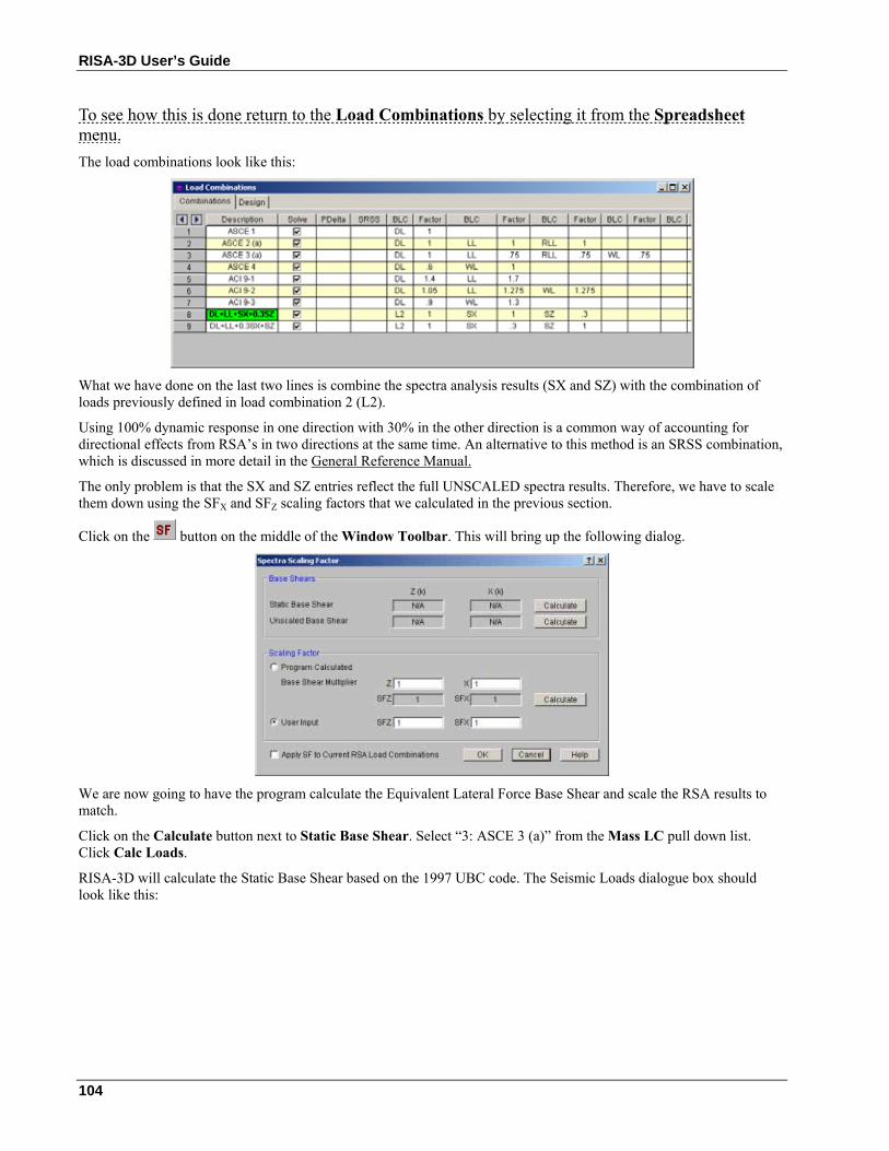
RISA-3D User’s Guide
104
To see how this is done return to the Load Combinations by selecting it from the Spreadsheet menu. The load combinations look like this:
What we have done on the last two lines is combine the spectra analysis results (SX and SZ) with the combination of loads previously defined in load combination 2 (L2).
Using 100% dynamic response in one direction with 30% in the other direction is a common way of accounting for directional effects from RSA’s in two directions at the same time. An alternative to this method is an SRSS combination, which is discussed in more detail in the General Reference Manual.
The only problem is that the SX and SZ entries reflect the full UNSCALED spectra results. Therefore, we have to scale them down using the SFX and SFZ scaling factors that we calculated in the previous section.
Click on the button on the middle of the Window Toolbar. This will bring up the following dialog.
We are now going to have the program calculate the Equivalent Lateral Force Base Shear and scale the RSA results to match.
Click on the Calculate button next to Static Base Shear. Select “3: ASCE 3 (a)” from the Mass LC pull down list. Click Calc Loads.
RISA-3D will calculate the Static Base Shear based on the 1997 UBC code. The Seismic Loads dialogue box should look like this:
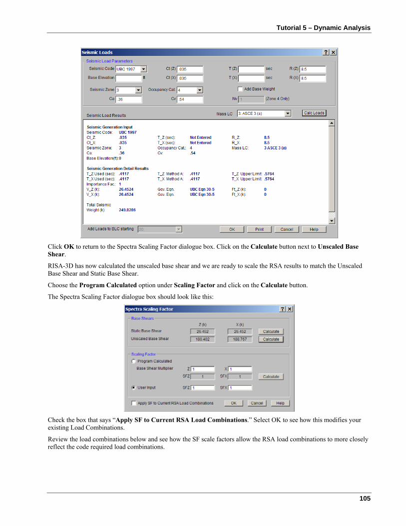
Tutorial 5 – Dynamic Analysis
105
Click OK to return to the Spectra Scaling Factor dialogue box. Click on the Calculate button next to Unscaled Base Shear.
RISA-3D has now calculated the unscaled base shear and we are ready to scale the RSA results to match the Unscaled Base Shear and Static Base Shear.
Choose the Program Calculated option under Scaling Factor and click on the Calculate button.
The Spectra Scaling Factor dialogue box should look like this:
Check the box that says “Apply SF to Current RSA Load Combinations.” Select OK to see how this modifies your existing Load Combinations.
Review the load combinations below and see how the SF scale factors allow the RSA load combinations to more closely reflect the code required load combinations.
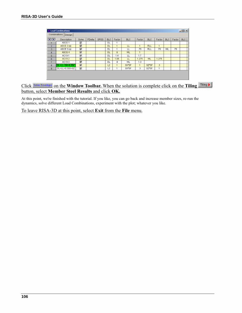
RISA-3D User’s Guide
106
Click on the Window Toolbar. When the solution is complete click on the Tiling button, select Member Steel Results and click OK. At this point, we're finished with the tutorial. If you like, you can go back and increase member sizes, re-run the dynamics, solve different Load Combinations, experiment with the plot; whatever you like.
To leave RISA-3D at this point, select Exit from the File menu.
Conclusion
107
Conclusion If you've completed the tutorials you should have a very good feel for how to use RISA-3D. Some of the topics we have not covered are listed below. You may not need all of these features but it is good idea to know they are available. Of course, if you wish to know more about specific features, you can refer to the RISA-3D General Reference or the On-line help system.
Model Generation RISA-3D has an expanding library of automatic generators that can quickly generate continuous beams, arcs, trusses, cylinders and numerous mesh layouts of our plate shell element. Click the button to access this feature. If nothing else, try the rectangular tank generator.
Moving Loads The standard AASHTO loads are built into the moving loads database and you can add custom moving loads as well.
Thermal Loads You can model temperature differentials causing axial expansion or contraction of members and plates.
Rigid Diaphragms RISA-3D allows you to quickly identify rigid planes that distribute forces to lateral force resisting systems.
Tension-Compression Only Members and Springs These features allow you to model one-way stiffness such as braces that cannot take compression or soil that can only resist compression.
Member Offsets You may rigidly offset the member ends to model rigid end zones and you may offset the tops of horizontal members to align member tops.
Story Drift, Joint Slaving and Enforced Displacements You may calculate and report inter-story drift, slave joints together or specify the displacement at a joint.
Tapered Members and Unequal Flanges You may specify tapered wide flanges or members with unequal flanges and design them per the Appendix F criteria.
If you have any questions, comments or suggestions feel free to call us at 949-951-5815, or FAX us at 949-951-5848 or e-mail us at [email protected].