Embed Size (px)
Citation preview

(J )COMPONENT PART NOTICE
THIS PAPER IS A COMPONENT PART OF THE FOLLOWING COMPILATION REPORT'
T .:,J -lej-atec{ Des i oa4" Adanced F,h+r . -
~Lo le Lnk m+d n -2 oL~
OY" To ORDER THE COMPLETE COMPILATION REPORT, USE _AD. -. L 5, _,%.
THE C'PONENT PART IS PROVIDED HERE TO ALLOW USERS ACCESS TO INDIVIDUALLY
AUTHORED SECTIONS OF PROCEEDING, ANNALS, SYMPOSIA, ETC. HOWE-VER, THE COMPONENTSHOULD BE CONSIDERED WITHIN 'THE CONTEXT OF THE OVERALL COMPILATION REPORT ANDNOT AS A STAND-ALONE IECHNICAL REPORT.
THE FOLLOWING COMPONENT PART NUMBERS COMPRISE THE COMPILATION REPORT:
AD#: ,AD#,,-
AD#: A#,, A -,
~. ., .u1987
A
~~.. . .. t.... . ...

jI
DESIGN OPTIMIZATION FOR A FMLY
OF MULTI-ROLE COMBAT AIRCRAFT
by
Jean-Claude HIRONDE
RAFALF Programme Manager
AVIONS MARCEL DASSAULT-BREGUET AVIATION78, Quai Mircel Dassault - 92214 SAiNT-CLOUD - FRANCE
SUMMARY
.The future multi-role combat aircraft desiqn process is used as an example throuqhout this lecture.At the early stage of the design, requirements of the French Air Force and Navy and other potentialcustomers (Eurpean and other countries) are studied very closely. Then the main technologicalimprovements - from the existing aircraft - that are needed to meet these requirements are clearlydefined. The improvements are achieved by an optimization process carried throughout each and allaircraft design disciplines, involving an intensive use of the very large range of design and testtools available from the aircraft company and state research establishments. Because of the numeroustechnical innovations which will be introduced in the future conbat aircraft, an in-flight demons-tration aircraft has been judged necessary, The RAFALE demonstration aircraft, and the evolutioninto a future family of multi-role specific versions, will be presented.
I - INTRODUCTION
Since its foundation, the AMD-BA company has conceived 9? prototypes, the RAFALEdemonstration aircraft being the latest in line (figure 1).
This experimental aircraft is part o1 the more general RAFALE programme, which concernsthe development and industrialization of a family of new generation combat aircraft, designedto equip the French Military Forces in the middle of the next decade.
The following description is intended to illustrate the process which ensures designoptimizat ion of this family of multi-role (:ombat aircraft.
2 - PEQUR EMENTS
At the early stages of design, it is essential to study very closely the requirementsof the staff of the French Air Force and of the French Navy and of other potential custoers
(European or other countries).
The French Air Force requires a multi-rol aircraft able to carry out ground strikemissions as well as air superiority missions and even air defence missions. It must cuvoran extensive flight envelope, have a manewver ohil ity as oc iaterl with a flyinq comfort sigo--f icantly higher than that of present (lay aircraft, be capable of operating from sho rt runways.Its carrying capacity and its weapons system shall ensure a large operational efficiency,which will also he Ilotained f rom it' iscrnticn (soe f i ot, ! ?).
Te French Navy requires defence ind air superiority aircraft to ens ure the protectionof its aircraft rarriprs and to carry out strike and r connaissarnc miss ons. The maneuverabilitycharacteri stircs reques ted are very c lose to those of the F rench Air Force ; the sane anpl in';to 1pproich s"ond, the th o ,-t0..owe i ht rati I the ( jrr',yiiq C, iea, ity of external torn' ,

3 HIf OPT IMIZATION PROCESS
The design of the new family of combat aircraft results from an optimization process,which takes into account, at the utmost, the interaction between the various disciplines involved,
such as aerodynamics, structure, propulsion, systems (see figure 3).
The more and more ambitious targets, involved by the previously mentioned reqiirements,as well as the essential target of the best cost/efficiency ratio, have moreove- required
extensive progress in the new technologies which have tbeen included in the optimization process.
3.1 - THE AERODYNAMIC CONFIGURATION AND THE AIR INTAKES
Many preliminary studies have been carried out, completed by wind tunnel tests.Several configurations adapted to the low speed targets have been studied (see figure
4). For cost and simplicity reasons, the compromise his been orientated towards a delta--
canard configuration. Performance in combat has been studied for various aircraft configu-rations (see figure 5) so as to determine the influence of the wing area, the aspect ratio,the thrust-to-weight ratio and thrust deflection devices or moving wing control surfaces.
Once again, the delta-canard configuration has proved to be superior.
On the basis of this configuration, several other possible solutions could be
studied concerning the position of the wings (high, medium, low), the position and number
of fins (sirg',e fin, fuselage or wing double fin), the position of the air intakes and
the type of protection .... (see figure 6).
Finally, the AMU-BA selected the following twin-engine configuration
- double sweep-back delta-wing with high aspect ratio,
- large area active canard fins,
- semi-ventral "pitot" air intakes,
- single fin with large rudder.
The choice of this new configuration is the fruit of long experience and of
the art of using it in the "fagon DASSAULT".
In fact this configuration is in line with the family of delta wing aircraft
which started with MIRAGE III aircraft and which, later, gave birth to MIRAGE 2000 aircraft
then to the "canard + delta wing aircraft" (see figure 7). This latter configuration dates
from the "MILAN" aircraft which, in 1969 with its retractable "nose fins", was the first
attempt within DASSAULT to decrease the relatively high approach speed of MIRAGE III aircraft(180 kts). Then in 1979 it was the MIRAGE 4000 aircraft and in 1982 the MIRAGE III NG
aircraft. The MIRAGE 4000 aircraft is equipped with fixed canard fins, designed to improveits maneuverability, which can be disengaged in caso of multiple failure of the flight
control system. This gives back stability to the aircraft and enables more traditionalflying control,
It is certain that the RAFALE demonstration aircraft and the new family of aircraft
which issues from it, will owe very much to the MIRAGE 4000 aircraft. This twin-engineaircraft has enabled experimentation of certain points inherent to the configuration retained
for the RAFAL[ aircraft. For instance, even though they are very different in size, it
is important to note that at the level of the shape and sweepback of the canards arid ofthe position of the wing leading edge relative to the canard, RAFALE is a certified truecopy of the MIRAGE 4000 aircraft.
For those who wonder why the "delta-winq" family has been momentarily interruptedwith the MIRAGE F1 aircraft, I would like to recall briefly that to qive a successor tothe MIRAGE III aircraft, DASSAUILT had chosen to abandon the delta configuration and toadopt the sweptback wing confiourition to decrease the approach speed from approximately180 kts to IMO kts with identical performance. The introduction of fly-by--wire controls,which enable artificial stabilization of an intrinsi(ally unstable aircraft, allowed usto re-use the delta configuration for the MIRAGE 2000 aircraft which, while offering anappreciable maneuverability gain, remained within the 140 kts approach speed.

0 3
To come back to the delta moving canard configuration such as it is on the RAFALEdemonstration aircraft, the advantages are multiple and we cannot go too far into details.This has already been done within the AGARD during a lecture at Trevise in April 86 byone iof our aeod ynamics engineers. We simply recall that this configuration enahles
- excellent wing efficiency, especially at high angles-of-attack, due to deflection ofthe air flow on the wing by the foreplane,
- extensive control of the aircraft's centre of gravity, thanks to the aerodynamic centreeffect created by the canard. As you know, it is the mastery of longitudinal balancethat guarantees high maneuverability throughout the flight envelope.
It has been proved in combat simulation that the negative static margin obtained,thanks to the fly-by-wire controls, which was optim-,,m, depends on the optimum limit ofmaneuver, itself corresponding to the best CL max. The selection of negative static marginthus made, a canard dimension linked to the selection of the aircraft c.g. position isobtained (see figure 8).
- a certain number of new FCS functions, as for instance gust alleviation, decisive formulti-role aircraft. In fact the possibility of delaying the accelerations felt by thepilot at high speed and low altitude (penetration mission) makes possible the selectionof larger wings which leads to an improvement of the aircraft qualities in the Air-to-Air dog fight (air superiority mission).
At last, linked to the delta canard configuration, the single fin solution hasproved to be the best one.
The semi-ventral pitot air intakes, which are of an entirely new design issuing from manycomputations and tests, meet specific technological requirements :
- improvement in air intake efficiency at high angle-of-attack thanks to the protectionprovided by the forward fuselage,
- improvement in the quality of air supplied to the engines by increasing the stationaryand unstationary homogeneity of the airflow,
- maintaining a Mach 2 capability, while at the same time achieving simplicity
no moving devices or bleeds,
- finally, complete separation of the right and left air intakes so that misfunctionsof one does not affect the other engine, and also to allow sufficient space for instal-lation of a forward retraction nose gear, leaving a large amount of space for carryinglong underfuselage stores.
3.? - SIZE
The selection of size is a decisive step in the fighter design process becausethen it creates an unavoidable restraint which will affect all other aspects.
From the requirements mentioned in the operational programme sheet which specifya certain number of data, studies of parameters lead to the selection of the optimal size.These studies cover the following main parameters
thrust,
- araa,
instantaneous turn rate (or approach ,peeI,
sustained turn rate,
- rate of climb,
- combat weight.
The effect of these parameters on the result is shown on figure g.
On the RAFALF demonstration aircraft, this optimization has allowed the Odesignof i twin-engine a;dl if oil df i i: ;'c t~ar t. -tho) exitinig (win-eninllt iir adtof equivalent installed thrust (TORNADO , F 18) and even much smaller than the other highlymotorized twiti-enqire aircraft (MIRAGF lm ), FlS , F4).
At last, it mrust be recalled that the aircraft size problem has been discus'Pdduring the L! uropEar cooperation feasibility studies with Egl1land, Germany, Italy and S pain.Siroe the size of the aiy-craft finally retained foi the tFA project was too large, Francehad to withdraw.
Since thi, the size of our design has heen re,:ons derod and rezduced, the basicve,'sion of the future aircraft is sinallor than tIho dominstratic air raft. with an emptywei(ght oif approximatel 1y tonn loss ; ts ' inensis arf, :cnparabl, to th MIRAG' ?i)Od
S e-erile in o air rraft ( ,(ee finiire 10d).
I- Allk-

0-4
3.3 - USE OF NEW MATERIALS
a) Composite materials
Since 1975 approximately, as shown on figure II, AMD-BA have achieved in thisfield a progressive and continuous step forward during which it is worth noting thatmilitary and commercial fields were complementary to one another.
This has only been possible by the use of a wise and strict methodologyshown on figure 12, consisting in dividing the development of any new solution into0hree stages :
- experimentation on the ground
- application in flight
- integration on aircraft.
In AMO-BA this methodology is applied for the introduction of ny new technology,whatever the field ma be, before going to industrialization.
Three main examples will highlight the spectacular character of the technologicalbreakthrough of AMD-BA in the field of composite materials :
- in 1978, the FALCON 50 was the first passenger transport aircraft with a vital component -the outer aileron - made of carbon fibre to be certified by the FAA,
- in 1979, the MIRAGE 4000 was the first aircraft to incorporate a large carbon fibreself-stiffened structure - the fin unit - also used as a fuel tank,
- in 1985, the FALCON VIOF was the first transport aircraft to be certified with a onehundred percent carbon fibre wing.
The so-obtained progress have been used in the RAFALE programme and firstly on thedemonstration aircraft. Composite materials are used not only for the control surfaces (elevons,rudder, canard), and the wings -for which a new high modulus fibre (IM6-.5245C) is used for the veryfirst time-, but also for the fuselage front section (cockpit structure (see figure 13), equipmentbay), central section (complete fuel tank) and rear section (below engine area).All landing gear doors as well as numerous access panels are made from composite material(see figure 14 and 15). The RAFALE demonstration aircraft also incorporates Aramid fibre fornumerous elements such as ,ing-to-fuselage fillets, fairings and the nose radome.
Altogether, composite materials account for over a fourth of the structure weight.
b) Aluminium-Lithium
To cope with the competition of composite materials, metal workers had tofind a solution : the aluminium-lithium alloys incorporate the required improvements.Indeed, with a proportion of 2.7 % of lithium for instance (beyond 3 % the metallurgicalbalances are broken) the density decrease is 10 % and the rigidity increase is 8 % relativeto conventional aluminium alloys.
With a view to an increasing use of these new alloys in our aircraft, studieshave been carried out in connection with the metal workers, they have more particularlydealt with :
- forging of ingots,
- thermal treatment,
- mechanical machining,
chemical machining (development of baths),
study of chromic anodic protection,
geometric evolution and redressing of parts durinq and after machining,
checking of weight saving and rigidity increase on samples and test parts.
Figure 16 shows the applications studied on the RAFALE demonstration aircraft.
[he zones retained deal with the fuselage skin panels and the inner panels of the enginetunnel. Furthermore, two fin attachment frames have been entirely machined.The use of masi pa t 1, under stldv and partci!!]orly depends oi the ed';ih h litv
of large blocks and the improvement of their mechanical properties.
Thuis, the use of Aluminium-1 ithium alloys could lead to a structural weightsaving of 10 to 15 % for the future aircraft, while keeping the means of transformationand manufacture used at the present tirne for conventional alloys.
IIIA_1 "_ "

c) SPFDB
This revolutionary technology which results from the combination of superpIlastiCforming and diffusion bonding, takes advantage of the property of some typrs of titaniumalloys to stretch by up to 8100 % and allows the manufacture, in a srqle hot formingoperation, from thin flat plates, of self-stiffened structura. elements of complex shape.
Since 1978, AMD-BA has developed this technique (see figure 17) : it has beenincorporated for the first time in production on the strake of MIRAGE 2000 aircraft.It has shown simultaneously, a rare occurence :
- a weight reduction due to the decrease in thickness ensured by titani,,m,
- a cost price reduction, involved by the fact that the baking cycle also achieves assemblyand enables the suppression of most fasteners.
The process has been used for the manufacture of the wing leading edge slatsof the RAFALE demonstration aircraft.
We are studying the extension of this process to other components such ascanards, air intakes, canopy framing,...).
Remarks
For technological reasons (limiting thickness of titanium) the weight reduction canbe subject to limitations, which leads to the idea of transferring the SPFDB to newaluminium alloys (SPF on aluminium already exists, but not the combination). An interestingexample can be seen here in which manufacturing problems lead to new metallurgical re-search.
d) Conclusion
As a whole, 35 % of RAFALE's structural mass are made from various new materials,which, as far as we know, constitutes a world premier for a combat aircraft.
On the future aircraft, their use will be at least as large but may be differentowing to the competition between aluminium-lithium alloys and composites.
3.4 - FLIGHT CONTROL SYSTEM
In this field also, the technological advance made in AMD-BA, marked very soonby the decisive stage which was the creation of the Dassault Equipment Division (see figure18), has each time given the answer to - and has even often gone beyond-the operationalrequirements.
Here again, the permanent compromise between the essential innovation and therespect of the traditions tending to use a maximum of proven solutions, has been the mainelement of the development of the flight control systems used on our aircraft.
Figure 19 shows this evolution in time and how we gradually replaced the simpledirect mechanical links by fly-by-wire control systems.
On the RAFAI.E demonstration aircraft a further step has been made with the genera-lization of digital systems.
The resulting CCV design. linked to the aerodynamic configuration retained,ensures an optimal ut;lizatioi of the numerous servo-controls (17 control surfaces and2 engine servo-controls (see fiqure 2O) ) and thus enables the introduction of a certainnumber of functions (see figure 21).
Some of them have already been tested in flight on the MIRAGE 2000 aircraft.The others, which are new, will be developed on the RAFALE demonstration aircraft to be,ifpossible, integrated in the future versions.
The use of optical fibre for data transmission will be evaluated.
3.r - AIRFRAME LAYOUT
It has become traditional within the AMD-BA to manufacture at the beginningof the design process an entire full-scale layout mock-up (see figure 21.
This mOCk-up becomes essential to fit out an aircraft of reduced size, us1ngfor the uirframe a large part of new materials where retrofit is difficult and receivinga large number of equipment (operational or ancillary equipment), which are not on theshelf and thp overall size of which has not beer entirely defined.
PA

Due to this mock-up, we can study and solve more easily and sufficiently soonthe problems of locatio;i of equipment and the problems of runninq thr' numerous relatedwiring and piping.
But it also enables every one, and in particular the future operational users,to help us all along the design, so ds to consider the correct accessibility to the circuitsand equipment.
Thus this method enables us to optimize the ease of operation and maintenance
of the aircraft. This aspect is of prime importance for the design of a family of multi-role aircraft (possible utilization on runways or on aircraft carriers).
3.6 - INSTALLATION OF THE PILOT AND MAN/MACHINE INTERFACE
Two main criteria, proper to future combat aircraft, had to taken into account,
in the design of the cockpit :
- the improvement of maneuverability in the entire flight envelope, which results in an
appreciable increase of accelerations (see figure 23) and of their duration,
- the extension of the operational functions of a multil-purDose weapons system.
Very soon, it seemed to us that an optimum answer to these two criteria wouldnecessarily lead to a complete revision of the installation of the pilot in the aircraftand, concurrently, to reconsider entirely the man/machine interface.
The difficulty of the problem has led us to examine all the solutions, includingthe most advanced ones (inclined ejection seat). This was covered by the OPE study (Orqa-nisation du Poste d'Equipaqe) initiated by the French Official Services.
The OPE study : following on a computer augmented anthropometric study, simple mock-ups have quickly shown that it was possible to work correctly in a highly reclined ejectionseat, provided that the upper par't of the torso is straightened up by a support at the level ofthe shoulder blades. With tests made in centrifugal machines we have checked that an anole up to500 ensures an excellent protection against load factors - the reclined position lowers theblood column between the brain and the heart.
Beyond that, the pilot started to have difficulties in breathing (chest extension).Moreover, as from a ce-tain inclination, the surfaces capable of receiving flying or opera-tional instrumentation were becoming non existent or inacessible.
Appl icat ion to theRAFA.LE demonstration aircraft
When defining the demonstration aircraft, it has heen decided to experimentin flight the solution studied within the OPE. Several problems, inherent to the reclinedinstallation of the ejection seat, remained to be solved :-to eject from the aircraft without delay and in good conditions in case of emergency.
That is to say to keep a sufficient ejection path,
- to cope with the quasi disappearance of the instrument panel.
Furthermore, we had to check if the perfor,nance of existinq ejection seats enabledthis type of installation since the main problem was the clearance above the fin duringejection. From this point, trajectory computations followed by tests have quickly provedfeasibility.
Thorough studies and detailed mockinq -up sessions have allowed us to obtain
a sat isFactory, original and ergonomic compromise r)ot ion, shown by f igores ?4 and 2 ).This new installation of the pilot and the new re .id man/machise interface can be brieflydescribed as follows :
- ejection seat inclined at a 320 back angle (possibility 37')
- flying control according to the HOTAS concept "hands on throttle and stick", with thecontrol stick on the right and a throttle lever on the left (only one control for twoengines), both having a low displacement and integrated controls. Their high position,assuciated with the presence of elbow rests, avoids blood accumulation in the, arms inderlarge load factors.
- flig t and mission parameters synthesized on displays gener'ated by the 1 itist techno!oqiesu(h as :
head-up displav with hn)lographic imaging,ead-level display collimated to inf inity,lateral multichromic head-down display,
-sso:.iated with a multi-function keyboard and voice, control.

The experiments in progress show, thanks to these improvements, that it. is ti 1possible to improve the comfort (reduced workload and physiological restraints) and thereforethe operational efficiency of the pilot, and to reject a certain trend of thought accordingto which man now constitutes a limitinq factor in the development of raodern combat aircraft.
It must he added to this, due particularly to a bubble canopy and very 'low positionof the canopy arches, that the pilot has an exceptional external visibility, which isin no way obstructed by the canards.
3.7 - GENERALIZED INTEGRATION OF THE AIRCRAFT SYSTEMS
With the RAFALE demonstration aircraft, a large step towards the general inte-gration of the systems has been made.
In addition to the flight controls which have been already mentioned, the aircraftsystems and circuits, such as fuel, hydraulics, electricity, air conditioning, enginecontrol, navigation and communications, make wide use of digital technology, with informationtransit and exchange oeing made over two centralized digital data bus lines. Thus thepilot does not have to worry about monitoring the systems ; he will only be warned inthe event of failure, if this is strictly necessary, and will be provided with the infor-mation required to take rapid and efficient action.
Experimentation in flight of this integration concept will enable the optimizationof the really necessary integration level in the future operational aircraft.
3.8 - STORES
Designing a multirole combat aircraft means providing a high weapon-carryingcapabiliy ; in this respect, the RAFALE is particularly well placed since it has, inaddition to its internal gun, twelve hardpoints allowing approximately 7 tonnes of externalstores to be carried.
We have already mentioned previously that the architecture of the aircraft airiatakes, nose and main undercarriages gives the capability for a large store to be carriedunder the fuselage, which is essential to achieve certain Air-to-Ground missions (seefigure 28).
Certain configurations, such as those with air-to-air missiles conformal tothe fuselage, have been designed especially to reduce drag and radar signature. Figure29 shows the configurations which have been tested in the wind tunnel for under fuselagetanden-mounted missiles. The structural optimi2zation has enabled the installation of themissile ejectors inside the aircraft.
This store carrying capacity, which is exceptional for an aircraft of this size,has been obtained by opting for a mid-fuselage wing location and desiqning a special linkaqesystem for the rose gear that minimizes the space required under the front section forretraction and extension of the qear.
lere we have (figure 30) an air-to-air configuration showing 8 MICA missilesand ? MAGIC missiles.
At last, its multitarg't capability stem also) from its aptitude to carry outlong range missions : to achieve t.hiis, it has a high internal fuel capacity. In fact theinternal fuel--t.o-eiipty weight ratio is the highest for filhter aircraft in this categvry,which reflects the, efforts made to optlmize the use of the aircraft's internal spa(e.
Figure 31 qives the envelmie of the Air-to-Grounl centfiquration,, with in parti-riu Iar the 2(1111) 1 Idrop tanks at winq -,t at ion 1.
4 M! AN f OR COMPUlTI AlP ) [I0FSIGN
Ihe geonralize d o timiIzat i o p,'ice's wh i(h we have just (Ih t r ihod, (Oil d n l y he at t iledt hlnik, tio the il; i derahle arid cent inons Ii ease Mof t ll d1, i a11 lre div(W iollnn iiii Ian" Wt nw ivkpropo's e to (:ois i der h,,i t I lv the ma ini illi ai V'a iI1 1 (.
1. IN (All A M C(A[IA (( ( (,pt , A,.' , It i n i 6 ililti , , ni 1 lnT1iA , t vi
Wi' ,tr' i li/ri th "il ,n t, ,ft-ni 1, i, I i y of i: v-ly)llk-jt ollI (q iT ,
u i I /ot i [ -lAll.
I T1 th1 i,: , I h, do, I i'lo , i 0 ,Vo1m I-,l tho ill 'A I hP 1),
. d r i'iw , 'tIT -
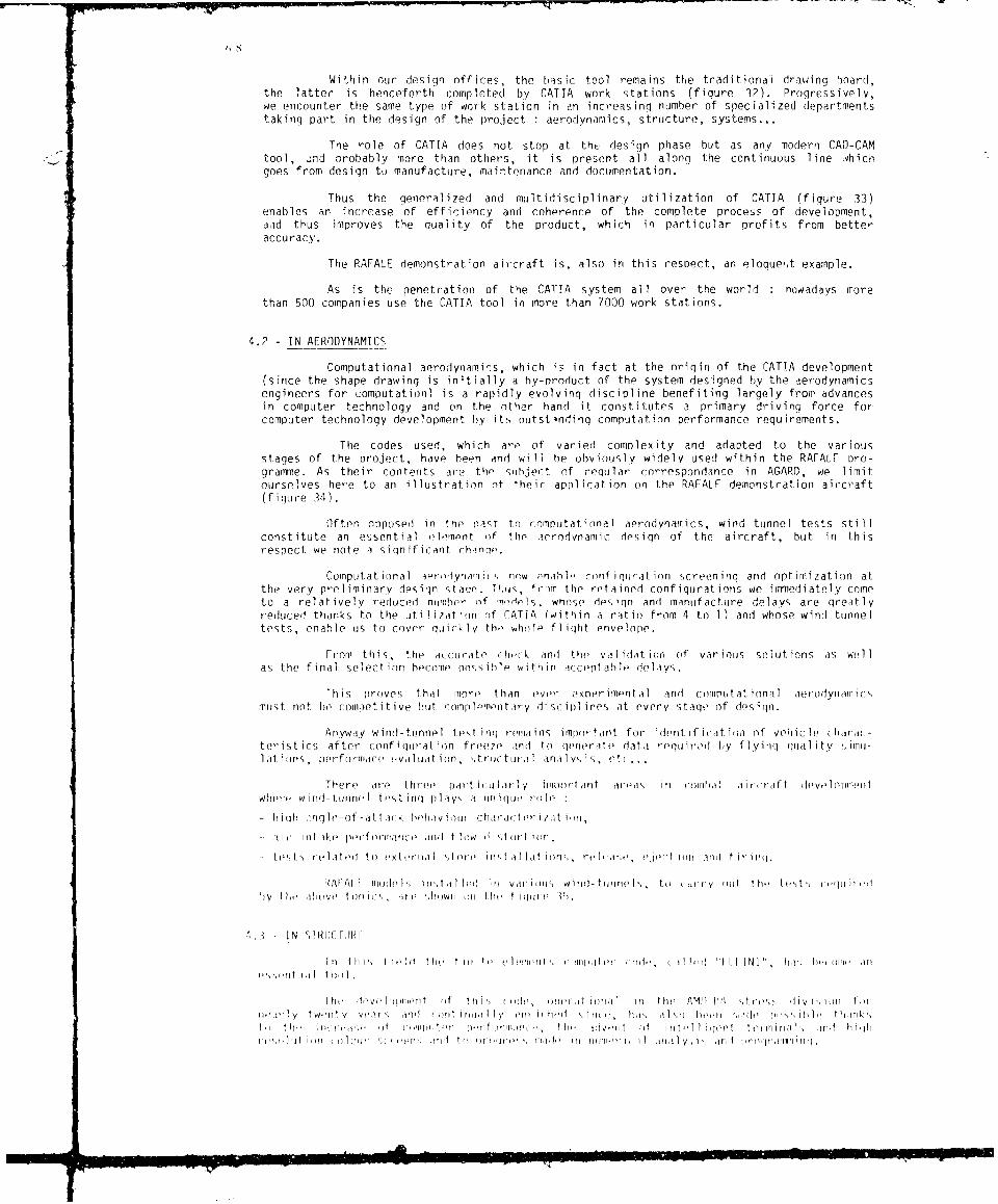
Within our design off ices, the I.,aSi41C tool remains the traditionai drawing board,the latter is henceforth completed by CATIA work stations (figure 32). Progressively,we encounter the same type of work station in an increasing number of specialized departmenprtstaking part in the design of the project. :aerodynamics, structure, systems...
The role of CATLA does not stop at th, design phase hut as any modern CAD-CAMtool, ind probably more than others, it is present all along the continuous line whichgoes front design tu manufacture, maintenance and documentation.
Thus the general ized andi multidisciplinary utilization of CATIA (figquire 33)enables an increase of efficiency and coherence of the complete procevs of development,aod thus improves the quality of the product, which in particular profits from betteraccuracy.
The RAFALE demonstration aircraft is, also in this respect, art eloquert example.
As is the penetration of the CATIA system all over the world :nowadays more
than 500 companies use the CATIA tool in more than 7000 work stations.
4.2 - IN AERODYNAMICS
Computational aerodynamin:s, which is in fact at the origin of the CATIA development(since the shape drawing is initially a by-nroduct of the system designed by the aerodynamicsengineers for computatio)n is a rapidly evolving discipline benefiting largely from advancesin computer technology and on the other hand it constitutes a primary driving force forcomputer technology development by its ntstindiog computation performance requirements.
The codes used, which are of varied comnlexity and adapted to the variousstages of the project, have been and wili be obviously widely used within the RAFALF pro-gramme. As their contents are the suhject of reqular correspondance in AGAR), we limitourselves here to an illustration of their appilication o0 the RAFALF demonstration aircraft(figure 34).
Often opposedi in the east tn compuitat ional aerodynamfics, wind tunnel tests stillconstitute an es sential elompnit of the arrodlvo-amic design of the aircraft, but in thisrespect we note a significant rhanqp.
Computational aet0roynrim1 r nw onah 1" roof igurat inn screen in rignd opt imi zat ion atthe very preliminary desiqn staqo. Tliis,, frvmm the retained configur-ations we immediately comnet 'o a relatively reduced nimiribe- f ndel whose decs gn and manufacture delays are greatlyreduced thanks to the util1ization of CtITIA (within a ratio from 4 to 1) and whose wind tunneltests, enable us to cover quicikly the whole fl iqht envelope.
From this, the a(Ccurate' ChOCk a nd the vaIi idAt ion (if varioius SOl uLt ions as wel 11as the f inalI selIect ion heromne poss i h If w it h in ac:cept ableIf delIa ys.,
rh is proves that more thban eveor - xpDer i me ntalI and romput at i ona I a e rodynaiicmust not. he comae ot i t: iye but 7omp 1 e'rm.'o tar y di Sr ip l ines, at every S tage of do:s igqn.
Anywa y w ind- tunnelI t est ig remna ins import ant for ident 1f icat io~i of vehiic le clhajrac-t er i st ircs af t er r oonf i (IurI-at, iocn f re e 7 1,aidt to (le nera tei (a ta reg (, ro t-d by flIy ing ( gotl i ty (1 at lonis, lmerforloarr evaltiait ion, ,truct titalI anal Iy-si s, 0eti
Th e re are thbr ee par t ic:uIa rlIy i ilir t ain t area'; illn 111 (11 ale i V -lIf t di t'leIif11 ' r Itwhere I-f w i r id - tuIin nel1 t ,,t i rni( p I ay,, a t un igqueit role f
- h igim fngte-of -att ark tmeliavioircaueruu
- i ft ike' merforirarice'In am! t w list rit ,
-- t(')t relateit to m'xtertiot "tor' ir'tallatimi',' rom;, e t Ion 11im1 ii
!l/uFI ! mill' it il i i v d i mVI )J Wim airml -tlrirlf, tim ( nmy it t lm' t 't I ' i "d
my tit t'lmivf' toiphii , ilm ,houwi oni tht- t ioiui' 1.
'''t ia tool,-
Ie l 've 1 m" immmi mo t ti I' f mm!', momefl l I t m in;ljl 1 tli.' PIMP !A ',trm'',% di I m i t
met IY twu W, IY yeal -mm il IorI fl l Immo Iv I 0m tol' ' lio, r, hi' mini mi mi'd ts im i l'tm
t (Iliil. III '.i) fi ' ti oeirf mmrmsn mn t htu muffi I if o tYf I' i r t r iii i n' hi Il
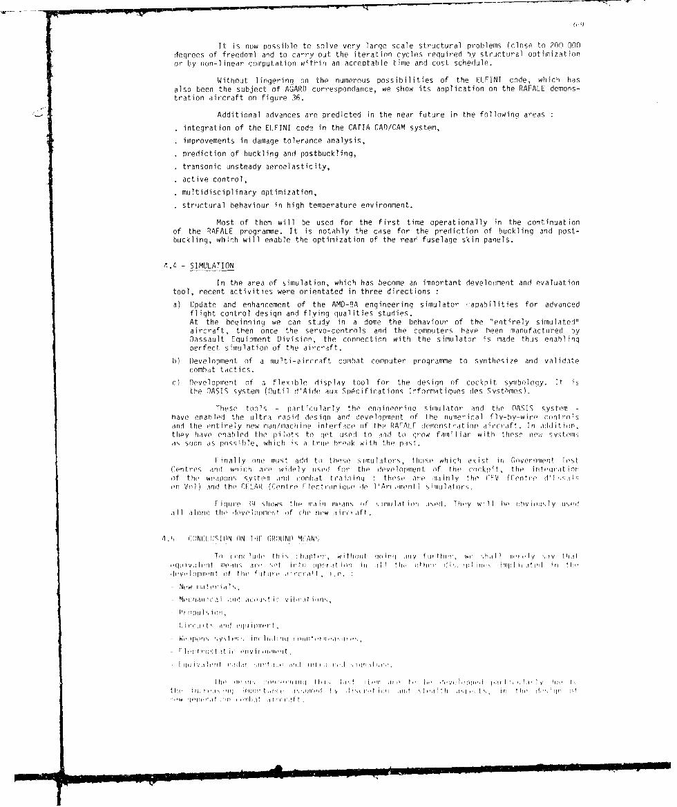
It is now possible to solve very large scale structural problems (close to 200 000degrees of freedom) and to carry out the iteration cycles required by structural optimizationor by non-linear computation within an acceptable time and cost schedule.
Without lingering on the numerous possibilities of the ELFINI code, which hasalso been the subject of AGARD correspondance, we show its application on the RAFALE demons-tration aircraft on figure 36.
Additional advances are predicted in the near future in the following areas
integration of the ELFINI code in the CATIA CAD/CAM system,
improvements in damage tolerance analysis,
prediction of buckling and postbuckling,
transonic unsteady aeroelasticity,
active control,
multidisciplinary optimization,
structural behaviour in high temperature environment.
Most of them will be used for the first time operationally in the continuation
of the RAFALE programme. It is notably the case for the prediction of buckling and post-buckling, which will enable the optimization of the rear fuselage skin panels.
4.4 - SIMULATION
In the area of simulation, which has become an important development and evaluationtool, recent activities were orientated in three directions :
a) Update and enhancement of the AMD-PA engineering simulator capabilities for advancedflight control design and flying qualities studies.At the beginning we can study in a dome the behaviour of the "entirely simulated"aircraft, then once the servo-controls and the computers have been manufactured byDassault Equipment Division, the connection with the simulator is made thus enablingperfect simulation of the aircraft.
b) Development of a multi-aircraft combat computer progranmie to synthesize and validatecombat tactics.
c) Development of a flexible display tool for the design of cockpit symbology. It isthe OASIS system (Outil d'Aide aux Sp#cifications Informatiques des Syst"Smes).
These tools - particularly the englineerinq simulator and the OASIS system -
have enabled the ultr, rapid design and development of the numerical fly-by-wire controlsand the entirely new man/machine interface of the RAFALF demonstration aircraft. In additin,they have enabled the pilots to get used to aid to grow familiar with these rnw SysteIsas soon as possible, which is a true break with the past.
Finally one must add to those simulators, tho,(, which exist in Government TstCent res and wn ich are widely used for the development of the cockpit, the intqritionof the weapons system and combat train inq : these are mainly the CFV (Centre d I 1,saien Vol) and the CFILAR (Centre F lectroni qu Ic, 1 'Arl men t ) simu 1ators.
Figure ?tg) show, the, main means of ,imtilation trsd. They will ho ()bviously useodal 1 lono th, levev uipmen of ihe new air'c aft.
4, CONCAISI IION ON IlF GRIINI) M[ANS
To (( -lu t' tli,, -hlpttr, withoiut q(oinq iiy furthr', we ih l lii _Iy th,itt'(Jl iv ,1)t,llt in, illm , Irf ' ', t i 1 "() ope t:, ,it i on ill 1! 1 tht, i, the (I i ,, i 1 l i t 'w , il l n( ,oto, l F) till,
dtvoelointiont of the futu , l t iroiicr t, i. .
New lleria I,-M ,(h,in icai ,:fld ,1t(oljt ic v ibr,it ion",,
Wituirt ;indto qulipitl lt,
Wo',lpofl%' ;y i "I ill( 111,11i q( t ) t t~ 'tl'lj i ,
1 q liiV ,llt'llt r',(l , f ,ll ~ lir ! ,fId Iflil r ,i r' ' ,li ll il *
I he1 15. t(i, ot nin( th i , 1 .1 t it i (" I) ' iti tu ' n)tit I it J I1'1y t ' t i
t t i filv I t'' i 1 ! 'l nlir J, o lllod l I I r it , t, t , tl l t t irl t l) ,
mlt q at 1111 IllIl I t I II itt

t' -- -.
In all these disciplines, the internal AMD-BA means and the means availableeither in the Government Test Centres or in private companies, are harmoniously complementaryto one another.
Thus, they form a solid basis to establish the Dassault validation methodology,which judiciously puts together computation and ground experiments before going to theultimate step : flight tests.
5 - FLIGHT TESTS
In this area, the RAFALE programme will be able to profit from 50 years of experience,which, thanks again to a well considered step-by-step policy, nowadays gives rise to an homo-geneous entity which is certainly unique in the world.
This entity, based on an original organization, uses particularly efficient means.
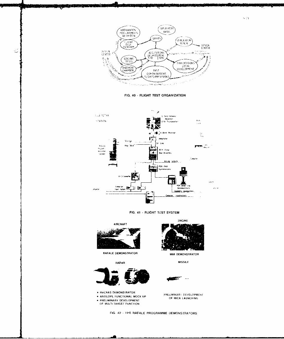
The organization is characterized by an initegration of flight tests in the previsions -partial tests - ground tests contrary to other companies or countries which differentiate clearlythe tlight tests from others even if they have to be integrated in specialized test centres. Figure40 illustrates our integration of the flight tests.
The means used are essentially made of :
- a recording/analyzing system of parameters collected on board based on telemetry, which,as far as we know, has no equivalent in technology and performance. The architecture ofthis system is shown on figure 41.
- an airborne numerical data acquisition system using leadinq technologies such as hybrid circuitswith LSI components as required. This system called "DANIEl_ 9q" and supplied by ElectroniqueSerge Dassault has a capacity of analysis of 32 000 pts/sec.
As far as we know, this system is one of the most efficient flying in Europe at the present time,well adapted to the acquisition of data on all types of diqihus (GINA, MIL-SDT-1553, COLLINS,PROLOG).
All this has already been used on the RAFALE demonstration aircraft, which has encoun-tered an unprecedented rate of fliqht in our coMpany.
The related test facility enables, all along the flight, a follow-up in real timeof nearly 100 parameters and enables the modification, if needs be, of the flight instructionsand/or warning the pilot of a deqradation of a parameter or an unexpected variation in fliqhtcondi tions.
6 - FXPIRIM[NTA[ SYSTEMS
In order to preoare the future combat aircraft, a set of experimmtal sys t eots havebeen 1minched in the main f ilds concerned hy the RAFAII progiramme. r irqure 4? shows this set.
As cnncerns the aircraft, it is the RAFAI I demonstrat ion air( raft , whic h we, hivwidl y Ii '.(s ed at I ll lOn this rejoirt. It" rohe was, let u'+ riLO<! I it Ott 1 ,gain, to inloqratin fliqht a maximum of new tchno oqes (see fiour, 1-1 and thus enahle throigh its exptli.
mRenrt at ion the t or intat ion of the ttchnic'll It( is ion" for the futuore air(raft.
It is also oot 's a refte ,re fe to ,ittdtt, the abi I it.y t<, ta''rry ott Vlr' ioi . towiti ',riotihly ihoe of tie Navy, is. witll ', t') ,tal i,.h tI !1v 5i' i 5 t lo d ,vi tlttpiirtt tist titI,.
A tit f sofhett i , tei fli ht te,;t- s r hdt, is ,ltiwn onl f l o t 4'l. Wo cart ,t it ipo',t i Iy th t I his air,:r tt has, hetn oartd tow proved thit, v l I it y if t(,, tinn p t I t lc it' ,ftr ti, f ttirt, a ircraf t , i o ( r irttm d the, (ttrimp tt e pe t toririitt.
As titn( rr',
t te ri trw , <,N ('MA h'is triotro 'i ,t Il ar M o ,, lh l oir l r ta njilto w ith i ', h t it tr'tirn i n I o n thI, t o 1t !wn( h fill Im , thall o~rw ir t ,lld Wh It Il lp I 1 1 1+ "l i, ,y Il~l ( V';t fit t fr tl,,t lit f' orl rl(m " . I hu It 11 P w t i ()rn ,f th , ~ i ' ontlI ,, hotl t.",t tII w d oe 1w, t,,f'd ,i . ,i h) , .
t or. th1 det it tintl ,PltiI u t tii t''\)t I ,Ilth ItQt t ,ut ii oi II I [tr tI I ltii i ,oif tit, IP pt . ltn 'q I h I'h ii c I ' tittIi .
t q f ,r 1 ,', th , - 1 1 , t ! t I " Ib , r + h v ' , ,ut tl, I, + r lo 11 1l t } t "l 11 1 1 " 11 ! i~l'
tilt'~ ~ ~ ~ ~ ~ ~~[ 01''} 11] It, .VN If, viP W! !'! ', ir tI!ll!h ,'rJ I l Ih 't
rII J .. . I i .... - -q -. t I o( Il IL I I l l ll . . .. 11 _, -- A
W , i rl I •l) 11,
As concerns the MICA missile, various designs were launched several years ago, concer-ning propulsion, seeker, launching system as wellI as its association with the multitargetfire controls.
By adding to these experimental systems other work relative to other componentsof the system and important steps in the discretion area, a large assembly of data has beenestablished to enable the selection of the finiAl configuration for the operational aircraft.
7 - THE FAMILY OF MULTIROLE COMBAT AIRCRAFT
All the work entered into within the RAFA.E programme, and already concretized bythe previously stated experimental systems, shall open nut on a new family of multimissionand multirole combat aircraft.
The optimized process described all along this report ensures the design of a basicversion for the French Air Force, adapted to its various operational missions - ground strike- air superiority or air defence.
From this basic version, it will be pos-sible to derive a version designed for theNavy thanks to the fact that we have taken into account, from the beginning of the process,tihe requirements proper to this version, namely
- low approach speed and increased visibility,
- installation of an undercarriage -.apable of receiving a specific: Navy landing gear withcatapulting by the nose gear,
- space available for the attachment of an arrester hook at the rear,
- large ground clearance.
For certain Furopean countries, RAFALF is an ailternativye air-craft, 1lighiter and cheaperthan the Eurofighter.
For export, RAFALF should hi' in Ole rariqi' of 7 to 10' tonnes aircraft, beyond MI1RAGIF2000 aircraft.
13 - CONCLU IO(NS
I n a re-port e,,t afhI i cued, iii I,/f by t hre Rand Corprorat ion on AV I i)N MARfOI DASSAPI F,we read
flassalt. tS firidalirt al I evlrp nt firt i (y i , t o m i I i m i ze te i , ix Ierit of teetihn ii-i I rY i ;k t hi fi s i rcu rr ei at anrly " jopte ( poinIft i n t lit,. A Ir ir~ a i rti f t fec, i rpi, i I tiior tii t ma y 1!)peoi f hrhoe novel irm ( 1" a 1y i ncorpr~iatoc nlo flirt Ih1 or rle ofr' tw~o iii iotie, fliinir- tfr i pIn ffi - . . .
Adopt irr (if cririe of t he' ofori it t he 1) - rrj I iirrr'o ri d we I I cliiri. Amiir i ) ii rift'in, I ti h t, ti f t ry t htiat iA c t bin, for tireo fret f r . "
I ht, ), rid nit if f ypre if 1 iqI i~ 11fi, . t hr f I i"p r inrt I it I f-Ift K t l",1 1 ti rve(Ilino fIif t ifi' runc t iiiolc aIrid rpI i equ 1c1 r ( f t of Irri (n 'ilI Iii' vit I ri , Win I n ponll " thwr1y fri Ii
qtriitiit mri if ouIrit ru ot, iiininiit 1i rf I( It I (ot I rnq rr I,

NEW GENERA'TION AIRCRAFT TO OPPOSE TO THlE VAPSOW PACT FORCES
REPLACEMENT OF MIRAGE III F AND JAGUAR AT LOW COST TO HAVE AVAILABLE
AIRCRAFT IN SUFFICIENT NUMBER
TH4REE MISSIONS OF EQUAL IMPORTANCES
III AIN SuPIRIORITV ABOVE NATIONAL TERRITORY AND BATTLE DISPOSITION
LONG RANGE AIR rO-tMOUYD AND INTEFFOICTOR STNIIIE
LONG LOITCR WITH 7LlG14T REFUELLING
C) 0 *GREAT AGILITY AND MANEUVERABILITY
USE OF SHORT OR DAMAGED RUNWAYS
'>~T ~ ~LOW oBsEflVAaLE C ARACTERISTICS
FIG. I -RAFALE DEMONSTRATOR IN FLIGHT FIG 2.1 FRENCH AIR STAFF REQUIREMENTS
FIG. 3 -THE AIRCAAFT PROCESS DESIGN FIG. 4 EXAMPLE OF LOW SPEED CONFIGURATIONSSTUDIED
PCESUL Ts
OF A SERLE OF DOI,,I IGIOTS
FIG 5 COMBAT PERFORMANCE OF NEW AIRCRAFT FIG. 6 -EXAMPLE OF DELTA-CANARDFORMULA CONFIGURATIONS STUDIED
CO~ STATIC MARGIN SELECTION
I..
SIR
IN(HIEASE Of
ANO CLo DECREASE, OF 1:1, MAX
FIG I FILIATION OF DELTA WING AIRCRAFT FIG. 8 NEGATIVE STATIC MARGIN SELECTIONADCREATION OF DELTA-CANARD AIRCRAFT

OPTI~UM
FIG. 9.- PARAMETER STUDY: AN EXAMPLE FIG. 10 - SIZE COMPARISON BETWEEN RAFALEOF OPTIMIZATION AND MIRAGE 2000
lPMCV~tFAN
- "~ ~RAFALE
FIG. 11 - COMPOSITE MATER!AL IN DASSAULT -BREGUETAIRCRAFT FROM MIRAGE III TO RAFALE
FIG. 12 - THE DEVELOPMENT STAGES OF A NEW FIG. 13 - RAFALE FRONT FUSELAGE CARBON FIBERTECHNOLOGY ELEMENT
FIG. 14 NEW MATERIALS IN RAFALE (BOTTOM VIEW) FIG. 15 - NEW MATERIALS IN RAFALE (TOP VIEW)

SUPERPLASTIC FORMING -DIFFUSION lSONi)INGMIRAGE 2000 STRAKE
1 "t' CONVfiNYIOMAI, *tAUTiON SOLUVION SPFfOi
FIG. 16 - Ii4TRODUCTION OF ALUMINIUM-LITHIUM STUDIEDON THE RAFALE
FORMING AT NO* C STRAKE ON INt AIARAIFT
regiured a ,teiv g-eerrtt fligh -noial., e-oi111 q to SPFOS SYRAKF
I)ASSiAtLT fitfFUtTJcIeded toc biill fitsflght SyStt'n.saIs cn, ,it ad I. tuse the ntehanicrrl ewpe'rice affjiind RFL EDN DESAloi the field it f profnellers ad engtne, The Daissau llt Equip-RFL EDN DESA
i-t btlstnno WEAD) Was tkii1, TACV SPFOBThe close an Iti runtriat ioperatir benten' the airfrandesigner and the manufa itsrertrlflightc ...tn f-sysierns hns
raft Pprfrnance With thre adoances in./tight sqstems. Itilsonopcratiloi has led tadalf to rnakinguirrrafti fly "IIstabtletsinftgsrsstont thanks l to ectitIlig.lit cstris
The I)Eift masters sucht technirat fields us sterhanicat skill." ign pt-essure hydraateis. setx.nrecharrisrns, anti roderna natogicat and digital Ptertmotlts With a solid experienceIn design as uell as In piadaction. VED1 car"ie aid slccifichighlpr W tr-rirtc flight cantrois deinited fot the aircraft artdtthen pwans far t)AS&AULL'RiGUFT nid , .1t'weromspatial uirnpantcs uiartdtifde.
FIG. 17 -SUPERPLASTIC FORMING -DIFFUSION BONDiNG
FIG. 18 - DASSAULT EQUIPMENT DIVISION APIAIN
SERVO, CON..TROL
MECHANICAL LINKAGE
- - - -- -(~%)FLY-BY-WIRE CONTROL' " WITH MECHANI~CAL BACK-UP
()BOOSTEDIMECHANICAL LINKAGEi
9-rF-nLSNV TCKI SERVO CONTROL
fw FEELUNIT
0 SERVO CONTROLLED LINKAGE I ARI
SE11T4O MiltROL
ACCELE EROME ii COMPUTER
CONMI QUADRUPLE REDUNDANTFLY-BY-WIRL CONTROL
0 STABILITY AUGMENTATION SYSTEM
FIG. 19 - FLIGHT CONTROL SYS fEM DEVELOPMENT
--A_
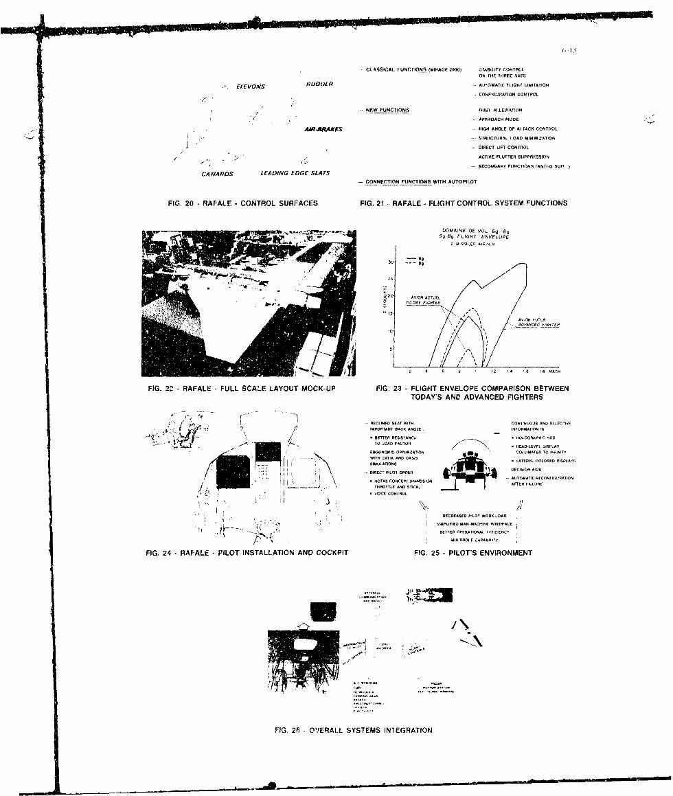
CLAS9SICAL FUNCTIONS. (MIRAGE 2000) -- STABILITY CONTROLON THE THREE AXES
EkEVONS RLID0fR -. AUTOMATIC FLIGhT LIMITATION
CONFIGURATION CONTROL
NfW FUNCTIONS -- UILT ALLEViATO
APPROACH MODE
AA*? BRAKE -~HIGH ANGLE OF AlI rACK CONTROL
.SYRICTURAL LOAD MINIMIZATION
-DIRECT LIFT CONTROL
- - - -ACTIVE FLUTTER SUPPFRESSIONA
-SECONDARf FUNCTIONS (AiO SUIT. I
CAf4ARDS LEADING EDGE SLA FV- ONNECTION FUNCTIONS WITH AUITOPILOT
FIG. 20 -RAFALF CONTROL SURFACES FIG. 21 .. RAFALE - FLIGHT CONTROL SYSTEM FUNCTIONS
LLOMAINE DE VOL 6g .8g
69 89 FLIGHT ENIVELOPE2 AISS).ED AIR/AIR
2.0
2 AV)ONACTLE
O TO LOAFOY=E
IAViON FulTU2
~~ ADVAFLCE0 F)CH2TEA
2 4 6 1 12 14 1 - 8 M C
FIG. 22 . RAFALE -FULL SCALE LAYOUT MOCK-UP FIG. 23 -FLIGHT ENVELOPE COMPARISON BETWEEN
TODAY'SNAND AANGNCND FIGHTERS
SLI E S&TWTONfINUOUS AND SELECTIVE
j.0 IT IMO NSC NL NORMATION IN
*BETTER RESI5 ANC 0 CAPI U
-TO LOAD FACTORHOGRPIHUHEAD-LEVEL DISPLAY
N- EROINOMIC OPTIMZATION 0OLLMATED TO INFINITY
WITH CATIA AND GASIS LATEAL COLORED DISPLA22SIMULATIONS
- DIECT ILO RDERAUTOMATIC TECONFIGIATION. ~ ~ ~S SO AIDSNEP (ADSO2 NOAS CNCEPRANT ONAFTER FAILURE
THROTTLE AND STICK)
-VOICF CONTNOL
DECREASED PILOT WORilA
2IIMFLIFIED MAN-MACSINE INTERIFACE
.- ~' BETTEP OPERATIONAL I FFICIEIVCT
7 A MULTIHOLE CAPAILITY
FIG. 24 -RAF-ALE -PILOT INSTALLATION AND COCKPIT FIG, 25 - PILOT'S ENVIRONMENT
FIG. 26 OVERALL SYSTEMS INTEGRATION

4 si(I' staitIiofS
wings I station capable olf onec 200 1O( cxtra, huel tank
I station capable of' one 1000O( kg load
I wing-tip station (self'-def'entce missile)
or 3 more carrying stations than on the Mirage 2000.
FIG. 27 - RAFALE - CARRYING CAPABILITY
FIG. 28 - RAFALE - IMPORTANT CARRYING CAPACITYUNDER FUSELAGE
UNDER PYLON FLUSH MOUNTED
CONFORMAL *z
FIG. 29 - RESEARCH OF MINIMUM DRAG FORUNDERFUSELAGE TANDEM MOUNTED MISSILES
FIG. 30 -RAFAI E 8 MICA 2 MAGIC CONFIG~URATION FIG, 31 RAI-ALE -CARRYING CAPABILITY

F.7-
FIG. 32 -CATIA WORK STATION
illS Si,\ 'oI THt SH,-PI S
CN' PTION LDFS FORHMES6A ,JDONNEES~ GEOMETRIOLI S
MISH FOA' fE fM SIRESS ANALY SIS 31) IDrs!N1vn "NI :1)(AI lyp, (IfMAILLAGL POUR CALCULS DE STRUCTURE A Ml (:FAtVI(Al P-ARIPAR ELEMENTS FINIS IELFINII CONCEPfION THILIMf NSIONNEL I I)[ 'I
H01csfIsPI# AAl cA1,11 KINEMATICS OF IANDING GEAR SAN~ 1f!AMtP~ETUDES DE ROSOTIQUE SPATIALE CINEMATtQUE DE 1RAIN OMTTERRISSAGE VISUALISA11ON QMBPAALL L)F LA Pl (J
CI DI SSLJS
N~ A IF /I , ATA H IN EMIA. , 0AMNAeME Of POSTE DE PILOTAGE Ofl8#M DE CIRCUIT ET Of WHIEM" ATTAC"E ARRIERE DE OEERIVE DU MIRAGE 2)
FIG. 33 -CATIA :CAD CAM SOFTWARE IN A MD-BA

lN
FIG. 34 -USE OF COMPUTATIONAL AERODYNAMICS CODES ON RAFALE
F WNDEI
FIG4 US5 WIN TMUTANNEL EN RAFLNAMIC ODESONAFE

FIG. 36 USE OF FINITE ELEMENT CODE "ELFINI" ON RAFALE
FIG. 37 STRUCTURE COMPARISON BETWEEN TEST AND COMPUTATION

FIG. 38 -STRUCTURAL TESTS
F'G. 39 -SIMULATORS
POTrARATION III II '"
MEAS URETENTS OASIS
OffINM~ON
TCUH STTIMIAO:1' rES fLNC:H eJ. PSI.
POORAM HNIF()I , N . . . -/, [ N
1I N ACQUISITIONS ,., _-OELAYETJ REAL
OROUNO TIME TIME-A-, EXPL OITATIONS
ANECHOID OA"W OF VELOPMENT "
S -F r COMPARAISONS
F LIOGH r s/PRE vi SION S ,2- -
FIG. 40 - FLIGHT TEST ORGANIZATION
7 A T I ON 1A T po.
!A AB P.0-,
k, ADp A.t.
A- --L
FIe1- LIH TS YSE
P(M PAM
FIG. 41 -FlIGHT TE~ST SYSTEM
ENGINE
AIRCRAFT
RAFALE DEMONSTRATOR M88 DEMONSTRATOR
RADAR MISSILE
" RACAAS DEMONSTRATOR PRELIMINARI, DAEVELOPMENT" ANTILOPE FUNCTIONAL MOCK-UP OF MIA LAUCHN
OF MICA LAUNCHING" PRELIMINARY DEVELOPMENT
OF MULTI-lARGET FUNCTION
FIG. 42 [HE RAFALE PROGRAMME OEMONSTRATORS

2 9
Nx
IFI-
4-
eC zt 2
04 5. Iz
FIG. ~ ~ ~ ~ ~ ~ ~ t 43-R4) NAVNE lCIOOYDMNTAO

- 1,, FLIGHT : 4, JULY 86 - M 1.3 / 36000 FT
*- M 1,8 AND LOAD FACTOR 8 g AT THE 51 FLIGHT - 1711 JULY 86
* 98 FLIGHTS,' 86 HOIJRS
- M 2 AT THE 9 3
1d FLIGHT - 41h MARCH 87
. FLIGHT ENVELOPE EXPLORED: M 2/ 600 KTS /47000 FT
. LOAD FACTORS SUSTAINED: 9 g / - 2 g
. AoA 31°
. APPROACH SPEED: 125 KTS
. MINIMUM SPEED: 100 KTS
. FULL DEFLrSCTION IN ROLL MANIEUVRE WITH RPU
. EXCELLENT AIR INTAKES BEHAVIOUR
9 VERY GOOD JUDGMENT BY THE PILOTS ON THL: NEW COCKPIT
o 8 PILOTS HAVE FLOWN 3 FROM THE SOCIETE AMD-BATHE AIRCRAFT 2 FROM FLIGHT TEST CENTRE
2 FROM THE FRENCH AIR FORCE1 FROM NAVAL AERONAUTICS
* MAIN COMMENTS OF OFFICIAL PILOTS :
- AFTER I'HE 11 th RAFALF FLIGHT (FIRST FLIGHT BEING DONE BY AN OFFICIAL PILOT)"GENERALLY SPEAKING, ON THE ISSUE OF THE FIRST FLIGHTS IS QUALITIES AND ONTHE WHOLE rIS TECHNOLOGICAL INNOVATIONS GIVE THE IMPRESSION OF A VERYBRIGHT, OUTSTANDING AIRCRAFT"
(FLIGHT TEST CENTRE)
-- THEN, FOLLOWING THE ASSESSMENTS BY OPERATIONAL PILOTS : ".. POWERFULAIRCRAFT, MODERN AND WELL SHAPED... EASY TO FLY... QUICK FAMILIARIZATION"
(FRENCH AIR FORCE)"THE WORK THAT HAS BEEN DONE, SHOULD ALLOW TO DESIGN AN ACT'ACM OF FIRSTCOMPETITIVE CLASS THERE IS NOT ANY DOUBT ABOUT THE POSSIBILITY OF THE"NAVALISATION" OF THE RAFALE
(NAVAL AERONAUTICS)
FIG. 44 - RAFALE DEMONSTRATOR - FLIGHT TESTS RESULTS (MARCH 87)
FL TL WIN,,INA
MI H' IA'" fg', L AIA .)!,
i WRG 1 A
~[Il MIRAG ill...
1960 1970 1980 1990 DMNRT
FIG 45 A FAMILY OF COMBAT AIRCRAFT


![[MS-SHLLINK]: Shell Link (.LNK) Binary File Format](https://img.dokumen.tips/doc/110x75/624f676ef2553e06f9713106/ms-shllink-shell-link-lnk-binary-file-format.jpg)