Embed Size (px)
Citation preview
�
SoundWire ScriptBuilder
User Manual
!
�
LnK44, rue des Combattants
B-4624 RomséeBelgium
SoundWire ScriptBuilder User Manual 1.35 Date: 9 February 2017 © LnK �1
Table of Content1. Introduction 42. Script Edition 52.1. Traffic Initialization 52.1.1. Hardware Control 62.1.2. Boot Information 72.1.3. GPI / PDM / PCM interface setup 72.1.4. Data Stream Content Management 10
2.1.4.1. PCM/PDM output tracking mode 102.1.4.2. Traffic Generator Stream Definition 102.1.4.3. PDM Input configuration 132.1.4.4. PDM Output Configuration 152.1.4.5. PCM Input configuration 162.1.4.6. PCM Output configuration 17
2.1.5. Traffic Generator Outputs 182.1.6. Script description 182.2. Sequence of Event 192.2.1. Specific Events 19
2.2.1.1. Bus Reset 192.2.1.2. Frame Start 202.2.1.3. Data Line Error 212.2.1.4. Stream Start & Stop 222.2.1.5. Hardware Loops 232.2.1.6. Set SSP 242.2.1.7. PDM Enable 242.2.1.8. Clock Pause 24
2.2.2. Control Words 262.2.2.1. PING 262.2.2.2. READ 262.2.2.3. WRITE 272.2.2.4. USER DEFINED 28
2.2.3. Macro Commands 282.2.3.1. Device Enumeration 292.2.3.2. Frame Shape Configuration 292.2.3.3. Channel Preparation 302.2.3.4. Data Port Configuration 302.2.3.5. Channel Configuration 312.2.3.6. PCMO Clock Configuration 312.2.3.7. Register Page Address 312.2.3.8. Prepare clock stop 322.2.3.9. Activate clock stop 322.2.3.10. Change Clock Gear 322.2.3.11. Debug Message Transmission 32
2.3. XML Script Generation 34
3. Additional Features 37
SoundWire ScriptBuilder User Manual 1.35 Date: 9 February 2017 © LnK �2

3.1. Stream Library Editor 373.2. BTP / BRA Transaction Definition 383.2.1. BRA transaction description file 383.2.2. BRA Transaction Activation 39
3.2.2.1. Create a Data Channel 393.2.2.2. Define a Traffic Generator Channel Content 413.2.2.3. Data Port 0 Configuration 413.2.2.4. Traffic Generator Stream Activation 423.2.2.5. BRA Block Fine Tuning 42
3.3. SWA Capture Parser 443.3.1. Frame Content 463.3.2. Slaves 473.3.3. Data Streams 483.3.4. BRA Blocks 493.3.5. Registers 503.3.6. Statistics 513.3.7. VCD File Import 513.4. Data Stream Viewer 533.4.1. Signal Analysis 533.4.2. Data Port Test Mode Verification 573.4.3. Data Export to File 583.5. GPI Logic Analyzer 603.6. Device Register Configuration 643.7. Device Library Editor 653.8. Script Automator 67
4. Success Criterions 694.1. Testable events 694.2. Test criterion edition 694.3. Type of tests 704.4. Test parameters 714.5. Test operations 714.6. Specific script test criterions 72
5. Remote Control and DLL 73
SoundWire ScriptBuilder User Manual 1.35 Date: 9 February 2017 © LnK �3

1. IntroductionScriptBuilder has 3 purposes:- It is a SoundWire protocol simulator, to some extent, allowing the user to see the effects
of the configuration sequences on the bus and the data streams. It also spot errors, both related to protocols and script execution.
- It generates from a given event list an XML script that can be directly fed in the SoundWire Traffic Generator. The tool allows quickly building a script by mostly using the mouse.
- Recuperate the SoundWire captured data to export commands and stream definitions to the editor.
The main window of ScriptBuilder is split in two zones. The first one on the left side contains the Core events that can be transmitted on SoundWire. The right one contains the list of events.
This manual will describe in details all the parameters the user can configure in a given entry of the Event list or in the Parameter list. For each entry, its translation onto the XML scripting language used by the SoundWire Traffic Generator will be shown.
To understand the functions and concepts used in that software, a good understanding of the SoundWire interface is required. Refer to the SoundWire specification for all the interface related technical details.
SoundWire ScriptBuilder User Manual 1.35 Date: 9 February 2017 © LnK �4
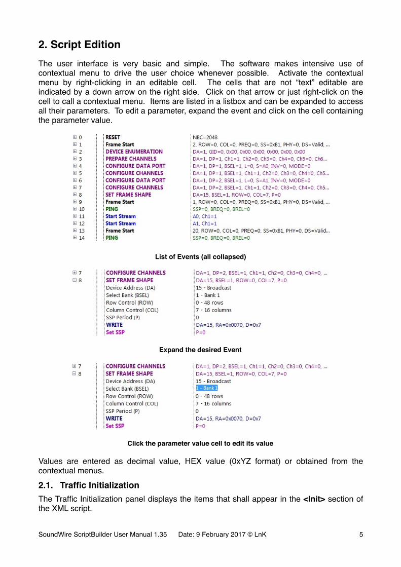
2. Script EditionThe user interface is very basic and simple. The software makes intensive use of contextual menu to drive the user choice whenever possible. Activate the contextual menu by right-clicking in an editable cell. The cells that are not “text” editable are indicated by a down arrow on the right side. Click on that arrow or just right-click on the cell to call a contextual menu. Items are listed in a listbox and can be expanded to access all their parameters. To edit a parameter, expand the event and click on the cell containing the parameter value.
�
List of Events (all collapsed)
�
Expand the desired Event
�
Click the parameter value cell to edit its value
Values are entered as decimal value, HEX value (0xYZ format) or obtained from the contextual menus.
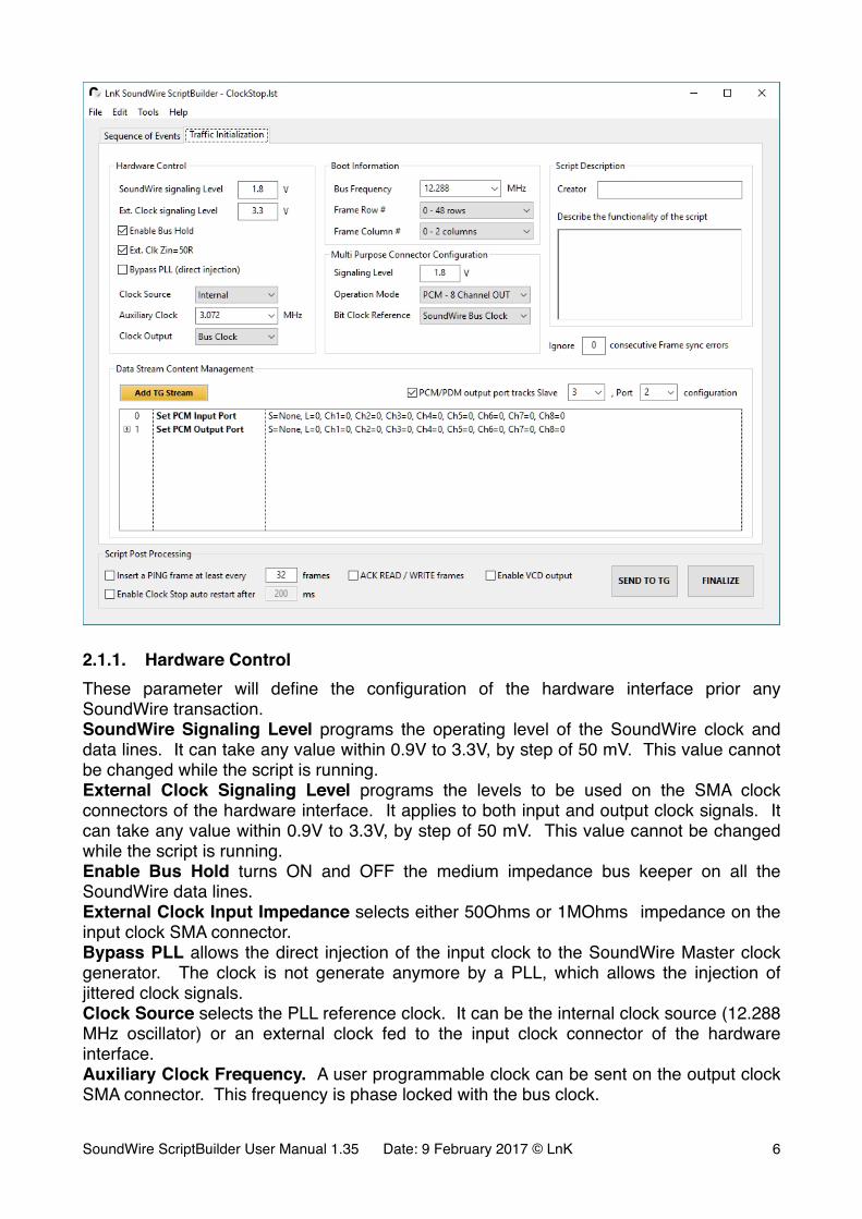
2.1. Traffic InitializationThe Traffic Initialization panel displays the items that shall appear in the <Init> section of the XML script.
SoundWire ScriptBuilder User Manual 1.35 Date: 9 February 2017 © LnK �5
�
2.1.1. Hardware ControlThese parameter will define the configuration of the hardware interface prior any SoundWire transaction.SoundWire Signaling Level programs the operating level of the SoundWire clock and data lines. It can take any value within 0.9V to 3.3V, by step of 50 mV. This value cannot be changed while the script is running.External Clock Signaling Level programs the levels to be used on the SMA clock connectors of the hardware interface. It applies to both input and output clock signals. It can take any value within 0.9V to 3.3V, by step of 50 mV. This value cannot be changed while the script is running.Enable Bus Hold turns ON and OFF the medium impedance bus keeper on all the SoundWire data lines.External Clock Input Impedance selects either 50Ohms or 1MOhms impedance on the input clock SMA connector.Bypass PLL allows the direct injection of the input clock to the SoundWire Master clock generator. The clock is not generate anymore by a PLL, which allows the injection of jittered clock signals.Clock Source selects the PLL reference clock. It can be the internal clock source (12.288 MHz oscillator) or an external clock fed to the input clock connector of the hardware interface.Auxiliary Clock Frequency. A user programmable clock can be sent on the output clock SMA connector. This frequency is phase locked with the bus clock.
SoundWire ScriptBuilder User Manual 1.35 Date: 9 February 2017 © LnK �6
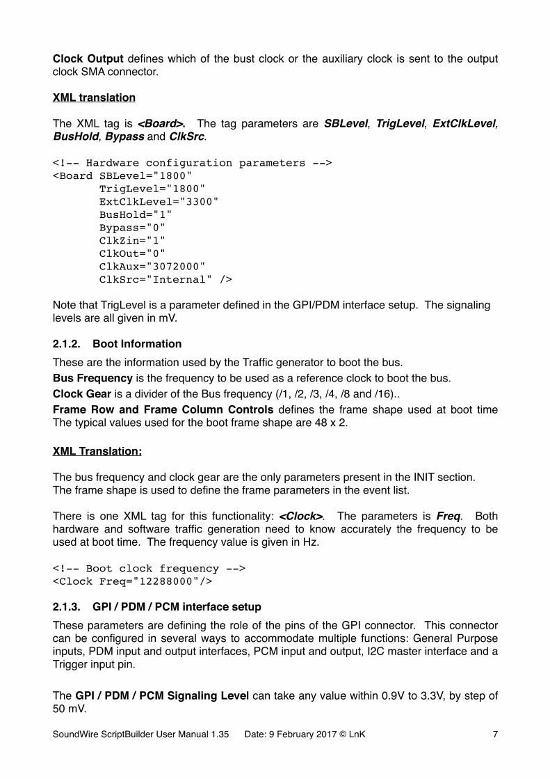
Clock Output defines which of the bust clock or the auxiliary clock is sent to the output clock SMA connector.
XML translation
The XML tag is <Board>. The tag parameters are SBLevel, TrigLevel, ExtClkLevel, BusHold, Bypass and ClkSrc.
<!-- Hardware configuration parameters --><Board SBLevel="1800" TrigLevel="1800" ExtClkLevel="3300" BusHold="1" Bypass="0" ClkZin="1" ClkOut="0" ClkAux="3072000" ClkSrc="Internal" />
Note that TrigLevel is a parameter defined in the GPI/PDM interface setup. The signaling levels are all given in mV.
2.1.2. Boot InformationThese are the information used by the Traffic generator to boot the bus.Bus Frequency is the frequency to be used as a reference clock to boot the bus.Clock Gear is a divider of the Bus frequency (/1, /2, /3, /4, /8 and /16)..Frame Row and Frame Column Controls defines the frame shape used at boot time The typical values used for the boot frame shape are 48 x 2.
XML Translation:
The bus frequency and clock gear are the only parameters present in the INIT section.The frame shape is used to define the frame parameters in the event list.
There is one XML tag for this functionality: <Clock>. The parameters is Freq. Both hardware and software traffic generation need to know accurately the frequency to be used at boot time. The frequency value is given in Hz.
<!-- Boot clock frequency --><Clock Freq="12288000"/>
2.1.3. GPI / PDM / PCM interface setupThese parameters are defining the role of the pins of the GPI connector. This connector can be configured in several ways to accommodate multiple functions: General Purpose inputs, PDM input and output interfaces, PCM input and output, I2C master interface and a Trigger input pin.
The GPI / PDM / PCM Signaling Level can take any value within 0.9V to 3.3V, by step of 50 mV.
SoundWire ScriptBuilder User Manual 1.35 Date: 9 February 2017 © LnK �7

�
� � �
FUNCTION
Pin 0 = GPI 1 = PDM 8 CH IN 2 = PDM 4 IN / 4 OUT 3 = PDM 8 CH OUT
1 I2C_SDA I/O I2C_SDA I/O I2C_SDA I/O I2C_SDA I/O
3 I2C_SCL IN I2C_SCL OUT I2C_SCL OUT I2C_SCL OUT
5 GPI6 IN PDM_BCKI OUT PDM_BCKI OUT PDM_BCKI OUT
7 GPI5 IN PDM_BCKO OUT PDM_BCKO OUT PDM_BCKO OUT
9 GPI4 IN PDM_SDI4 IN PDM_SDO4 OUT PDM_SDO4 OUT
11 GPI3 IN PDM_SDI3 IN PDM_SDO3 OUT PDM_SDO3 OUT
13 GPI2 IN PDM_SDI2 IN PDM_SDI2 IN PDM_SDO2 OUT
15 GPI1 IN PDM_SDI1 IN PDM_SDI1 IN PDM_SDO1 OUT
17 GPI0 IN GPI0 IN GPI0 IN GPI0 IN
19 TRIG IN IN TRIG IN IN TRIG IN IN TRIG IN IN
FUNCTION
Pin 4 = PCM 8 CH IN 5 = PDM 8 CH OUT
1 I2C_SDA I/O I2C_SDA I/O
3 I2C_SCL OUT I2C_SCL OUT
5 PCM_BCLK OUT PCM_BCLK OUT
7 PCM_LRCLK OUT PCM_LRCLK OUT
9 PCM_SDI4 IN PCM_SDO4 OUT
11 PCM_SDI3 IN PCM_SDO3 OUT
13 PCM_SDI2 IN PCM_SDO2 OUT
15 PCM_SDI1 IN PCM_SDO1 OUT
17 GPI0 IN GPI0 IN
19 TRIG IN IN TRIG IN IN
SoundWire ScriptBuilder User Manual 1.35 Date: 9 February 2017 © LnK �8

When using the PCM hardware interface function, additional clock parameters must be provided.
�
The PCM clocks can come from many sources.The default is the SoundWire bus clock.
�
This option covers two distinct configurations and assumes that flow control is not used:- The bit clock can be derived from the SoundWire clock by an integer divider. For
instance, a bus clock of 12.288 MHz will allow the use of a bit clock of 3.072 MHz (Fs=48kHz).
- The bit clock cannot be derived from an integer divider and requires a PLL to generate a bit clock based on the SoundWire clock. A typical example is the use of a bus clock of 9.6 MHz and a sample rate of 48kHz. The use of a PLL implies that the audio clocks might not be stable at the activation of the data port. Some delay (a few ms) might be required between bus start-up and channel activation.
The second option is to use the analyser PLLs to generate the desire bit clock and word clocks. The sample rate must be specified. The audio PLL uses the same clock reference as the traffic generation (Master) of the tool. This option can be used with isochronous data (no flow control) if the tool Master is used.
�The third option consists in feeding an audio master clock to the GPI0 pin. This clock is used to generate the bit clock and the word clock. A divider must be specified to define the ratio between the master clock and the bit clock. The word clock is always 64 times smaller than the bit clock.This option is foreseen to use the flow control modes of the PCM data port. Note that as of today, the flow control modes are not implemented yet in the data ports.
��
��
��(;7B3//�0&/.
0&/.�RQ�*3,�
��[�6:B&/.
(;7B&/.B6(/�����
��1 �
�'&0B%&/.
%&/.B6(/
����
,�6B%&/.
,�6B/5&/.
SoundWire ScriptBuilder User Manual 1.35 Date: 9 February 2017 © LnK �9

�
XML Translation:
The bus frequency and clock gear are the only parameters present in the INIT section.The frame shape is used to define the frame parameters in the event list.
There is one XML tag for this functionality: <GPIO> with the parameter Function.
<!-- GPIO configuration parameters --><GPIO Function="5" BCKI="3072000" BCKO="3072000" />
2.1.4. Data Stream Content ManagementThe list has 2 default entries related to the PDM input and output functional blocks. The traffic generator also has an embedded tone generator that can feed data streams.
�
2.1.4.1. PCM/PDM output tracking modeThe PCM/PDM output can track the configuration commands of a given data port of any given Slaves. It will get automatically configured and will output the correct data. When using PCM, the clocks need to be configured through a specific Macro (see Application Note for more details). Check the PCM/PDM output port tracking check box and specify the Slave number / port number to enable that feature.
2.1.4.2. Traffic Generator Stream DefinitionTo add a Traffic Generator stream definition in the list, click on the “Add TG Stream” button. An entry named “Set TG Stream” will appear in the list. Note that there can be many of these entries, each one defining a specific data stream content.All the events that are related to a data stream point to a stream ID, which in turns provide all the necessary information to handle the stream actions adequately. ScriptBuilder embed a Stream Library Editor (see section 3.1 for further information).
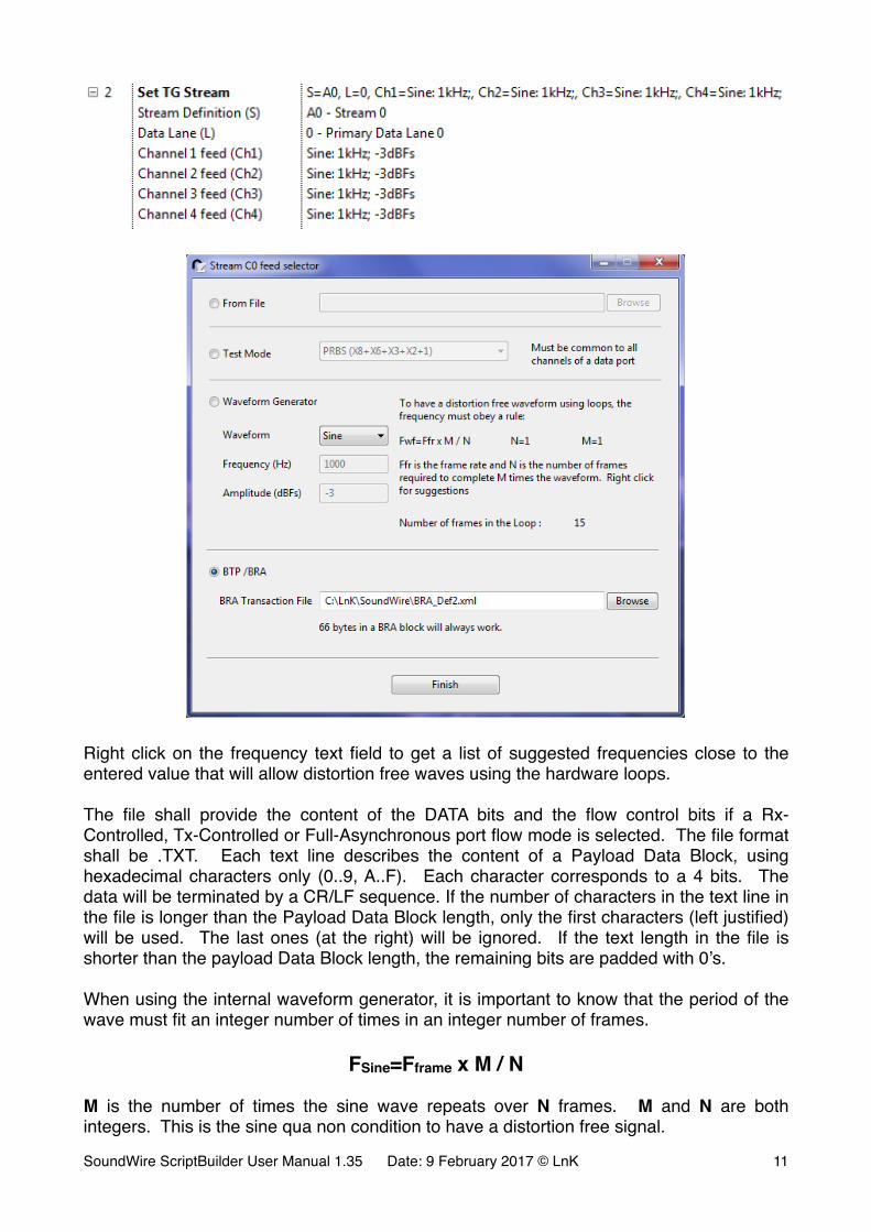
The data channel can be fed by a wave form (Sine, Square…), the SoundWire data port test patterns (PRBS, Static0, Static1) or the content of a data file. Right-click on the Channel x feed parameter cell to get access to a channel feed selector window.
SoundWire ScriptBuilder User Manual 1.35 Date: 9 February 2017 © LnK �10
�
�
Right click on the frequency text field to get a list of suggested frequencies close to the entered value that will allow distortion free waves using the hardware loops.
The file shall provide the content of the DATA bits and the flow control bits if a Rx-Controlled, Tx-Controlled or Full-Asynchronous port flow mode is selected. The file format shall be .TXT. Each text line describes the content of a Payload Data Block, using hexadecimal characters only (0..9, A..F). Each character corresponds to a 4 bits. The data will be terminated by a CR/LF sequence. If the number of characters in the text line in the file is longer than the Payload Data Block length, only the first characters (left justified) will be used. The last ones (at the right) will be ignored. If the text length in the file is shorter than the payload Data Block length, the remaining bits are padded with 0’s.
When using the internal waveform generator, it is important to know that the period of the wave must fit an integer number of times in an integer number of frames.
FSine=Fframe x M / N
M is the number of times the sine wave repeats over N frames. M and N are both integers. This is the sine qua non condition to have a distortion free signal.
SoundWire ScriptBuilder User Manual 1.35 Date: 9 February 2017 © LnK �11
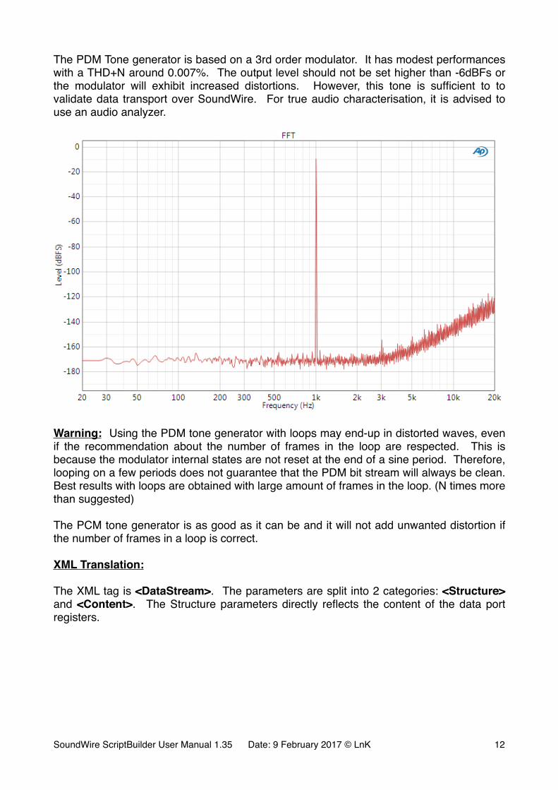
The PDM Tone generator is based on a 3rd order modulator. It has modest performances with a THD+N around 0.007%. The output level should not be set higher than -6dBFs or the modulator will exhibit increased distortions. However, this tone is sufficient to to validate data transport over SoundWire. For true audio characterisation, it is advised to use an audio analyzer.
�
Warning: Using the PDM tone generator with loops may end-up in distorted waves, even if the recommendation about the number of frames in the loop are respected. This is because the modulator internal states are not reset at the end of a sine period. Therefore, looping on a few periods does not guarantee that the PDM bit stream will always be clean. Best results with loops are obtained with large amount of frames in the loop. (N times more than suggested)
The PCM tone generator is as good as it can be and it will not add unwanted distortion if the number of frames in a loop is correct.
XML Translation:
The XML tag is <DataStream>. The parameters are split into 2 categories: <Structure> and <Content>. The Structure parameters directly reflects the content of the data port registers.
SoundWire ScriptBuilder User Manual 1.35 Date: 9 February 2017 © LnK �12
<!-- Stream A0 - 6 Ch 48k/16b --><DataStream Id="A0" > <Structure Channels="6" Interval="512" Hstart="1" Hstop=“8" Offset="0" Length="16" Protocol=“0" BlockPackingMode=“0” BlockGroupCount=“1" SubOffset="0" Lane="0"> <Content ChID="0" Wave="Sine" Freq="1000" Amplitude="-3dBFs"> <Content ChID="1" Wave="Sine" Freq="1000" Amplitude="-3dBFs"> <Content ChID="2" Wave="Sine" Freq="1000" Amplitude="-3dBFs"> <Content ChID="3" Wave="Sine" Freq="1000" Amplitude="-3dBFs"> <Content ChID="4" Wave="Sine" Freq="1000" Amplitude="-3dBFs"> <Content ChID="5" Wave="Sine" Freq="1000" Amplitude="-3dBFs"></DataStream >
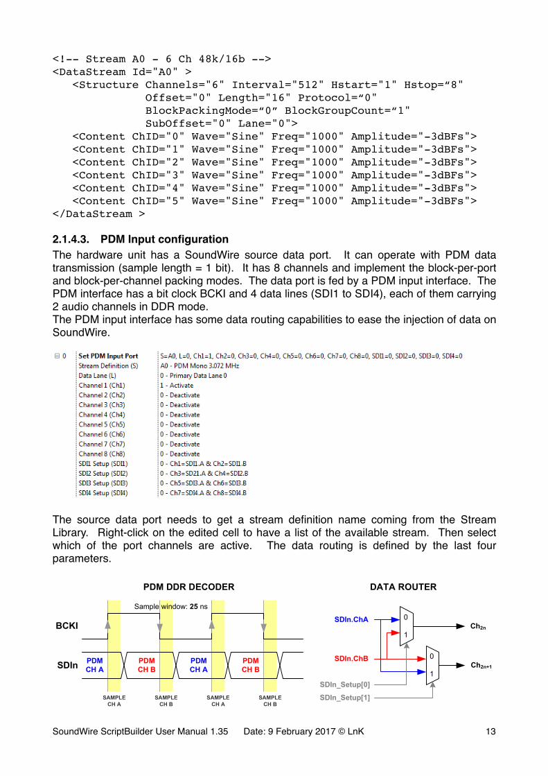
2.1.4.3. PDM Input configurationThe hardware unit has a SoundWire source data port. It can operate with PDM data transmission (sample length = 1 bit). It has 8 channels and implement the block-per-port and block-per-channel packing modes. The data port is fed by a PDM input interface. The PDM interface has a bit clock BCKI and 4 data lines (SDI1 to SDI4), each of them carrying 2 audio channels in DDR mode.The PDM input interface has some data routing capabilities to ease the injection of data on SoundWire.
�
The source data port needs to get a stream definition name coming from the Stream Library. Right-click on the edited cell to have a list of the available stream. Then select which of the port channels are active. The data routing is defined by the last four parameters.
�
BIT CLOCK
SoundWireSource
Port
ControlRegisters
DATA ROUTER
DATA ROUTER
DATA ROUTER
DATA ROUTER
Ch 1
Ch 2
Ch 3
Ch 4
Ch 5
Ch 6
Ch 7
Ch 8
PDM DDRDECODER
PDM DDRDECODER
PDM DDRDECODER
PDM DDRDECODER
SDI1.ChA
SDI1.ChBSDI1
SDI2
SDI4
SDI3
BCKI
8
PDMCH A
PDMCH A
PDMCH B
PDMCH BSDIn
BCKI
SAMPLECH A
SAMPLECH B
SAMPLECH A
SAMPLECH B
Sample window: 25 ns0
1
0
1SDIn_Setup[0]
SDIn_Setup[1]
SDIn.ChA
SDIn.ChB
Ch2n
Ch2n+1
SDI2.ChA
SDI2.ChB
SDI3.ChA
SDI3.ChB
SDI4.ChA
SDI4.ChB
DATA ROUTERPDM DDR DECODER
SoundWire ScriptBuilder User Manual 1.35 Date: 9 February 2017 © LnK �13
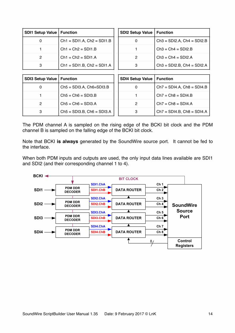
The PDM channel A is sampled on the rising edge of the BCKI bit clock and the PDM channel B is sampled on the falling edge of the BCKI bit clock.
Note that BCKI is always generated by the SoundWire source port. It cannot be fed to the interface.
When both PDM inputs and outputs are used, the only input data lines available are SDI1 and SDI2 (and their corresponding channel 1 to 4).
�
SDI1 Setup Value Function SDI2 Setup Value Function
0 Ch1 = SDI1.A, Ch2 = SDI1.B 0 Ch3 = SDI2.A, Ch4 = SDI2.B
1 Ch1 = Ch2 = SDI1.B 1 Ch3 = Ch4 = SDI2.B
2 Ch1 = Ch2 = SDI1.A 2 Ch3 = Ch4 = SDI2.A
3 Ch1 = SDI1.B, Ch2 = SDI1.A 3 Ch3 = SDI2.B, Ch4 = SDI2.A
SDI3 Setup Value Function SDI4 Setup Value Function
0 Ch5 = SDI3.A, Ch6=SDI3.B 0 Ch7 = SDI4.A, Ch8 = SDI4.B
1 Ch5 = Ch6 = SDI3.B 1 Ch7 = Ch8 = SDI4.B
2 Ch5 = Ch6 = SDI3.A 2 Ch7 = Ch8 = SDI4.A
3 Ch5 = SDI3.B, Ch6 = SDI3.A 3 Ch7 = SDI4.B, Ch8 = SDI4.A
BIT CLOCK
SoundWireSource
Port
ControlRegisters
DATA ROUTERCh 1
Ch 2PDM DDRDECODER
SDI1.ChA
SDI1.ChBSDI1
BCKI
8
PDMCH A
PDMCH A
PDMCH B
PDMCH BSDIn
BCKI
SAMPLECH A
SAMPLECH B
SAMPLECH A
SAMPLECH B
Sample window: 25 ns0
1
0
1SDIn_Setup[0]
SDIn_Setup[1]
SDIn.ChA
SDIn.ChB
Ch2n
Ch2n+1
DATA ROUTERPDM DDR DECODER
DATA ROUTER Ch 4PDM DDRDECODER SDI2.ChBSDI2
DATA ROUTER Ch 6PDM DDRDECODER SDI3.ChBSDI3
DATA ROUTER Ch 8PDM DDRDECODER SDI4.ChBSDI4
Ch 3
Ch 5
Ch 7
SDI2.ChA
SDI3.ChA
SDI4.ChA
SoundWire ScriptBuilder User Manual 1.35 Date: 9 February 2017 © LnK �14
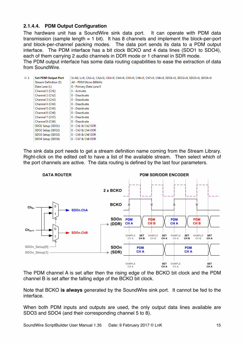
2.1.4.4. PDM Output ConfigurationThe hardware unit has a SoundWire sink data port. It can operate with PDM data transmission (sample length = 1 bit). It has 8 channels and implement the block-per-port and block-per-channel packing modes. The data port sends its data to a PDM output interface. The PDM interface has a bit clock BCKO and 4 data lines (SDO1 to SDO4), each of them carrying 2 audio channels in DDR mode or 1 channel in SDR mode.The PDM output interface has some data routing capabilities to ease the extraction of data from SoundWire.
�
The sink data port needs to get a stream definition name coming from the Stream Library. Right-click on the edited cell to have a list of the available stream. Then select which of the port channels are active. The data routing is defined by the last four parameters.
�The PDM channel A is set after then the rising edge of the BCKO bit clock and the PDM channel B is set after the falling edge of the BCKO bit clock.
Note that BCKO is always generated by the SoundWire sink port. It cannot be fed to the interface.
When both PDM inputs and outputs are used, the only output data lines available are SDO3 and SDO4 (and their corresponding channel 5 to 8).
SoundWire
Sink
Port
DATA ROUTERPDM SDR/DDR
ENCODER
Ch 1
Ch 2
SDO1.ChA
SDO1.ChB SDO1
Control
Registers
BIT CLOCK
PDM
CH A
PDM
CH A
PDM
CH B
PDM
CH B
SDOn
(DDR)
BCKO
2 x BCKO
SAMPLE
CH A
SET
CH B
SAMPLE
CH B
SET
CH A
SAMPLE
CH A
SET
CH B
SAMPLE
CH B
SET
CH A
PDM
CH A
PDM
CH A
SAMPLE
CH A
SAMPLE
CH A
SET
CH A
SET
CH A
BCKO
44
DATA ROUTERPDM SDR/DDR
ENCODER
Ch 3
Ch 4
SDO2.ChA
SDO2.ChB SDO2
DATA ROUTERPDM SDR/DDR
ENCODER
Ch 5
Ch 6
SDO3.ChA
SDO3.ChB SDO3
DATA ROUTERPDM SDR/DDR
ENCODER
Ch 7
Ch 8
SDO4.ChA
SDO4.ChB SDO4
SDOn
(SDR)
0
1
0
1
Ch2n
Ch2n+1
SDOn_Setup[0]
SDOn.ChA
SDOn.ChB
SDOn_Setup[1]
DATA ROUTER PDM SDR/DDR ENCODER
SoundWire ScriptBuilder User Manual 1.35 Date: 9 February 2017 © LnK �15
�
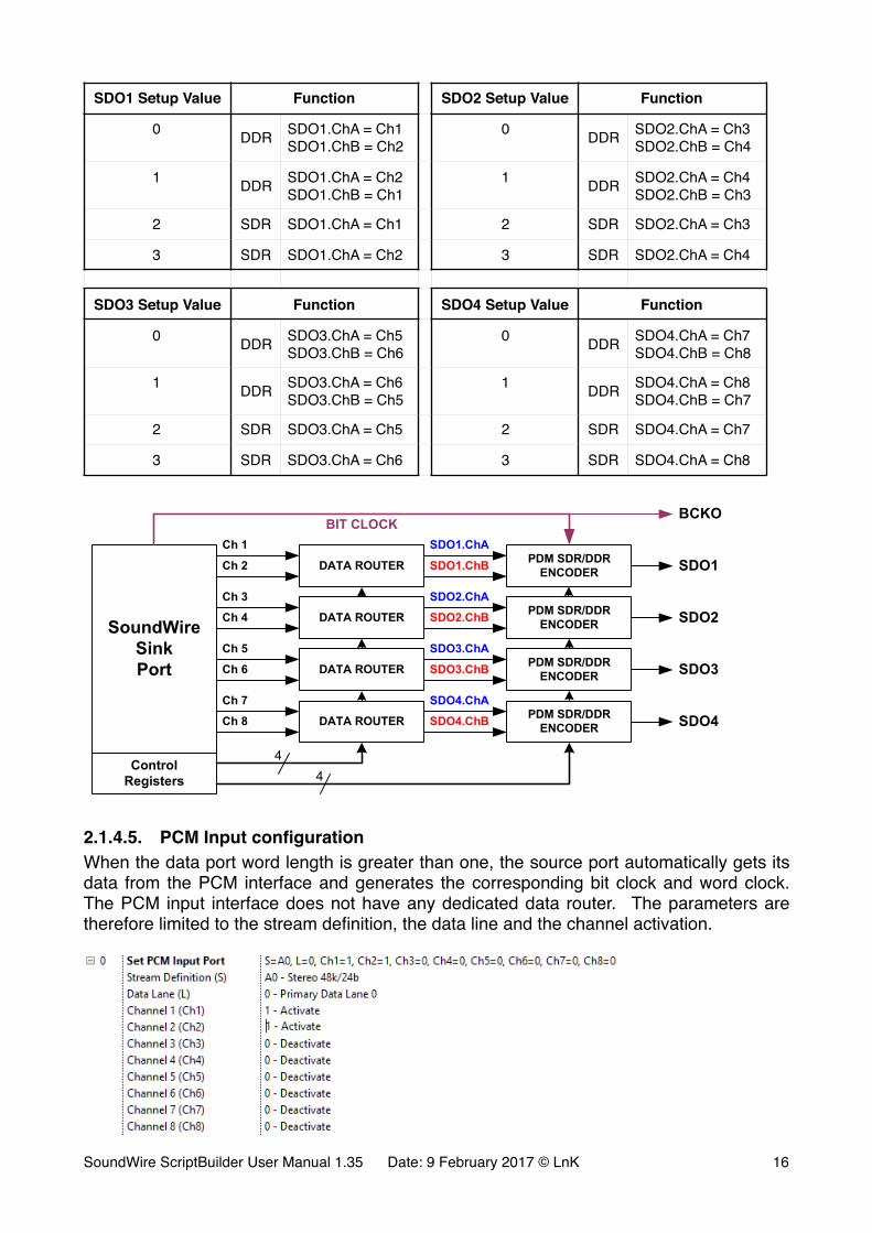
2.1.4.5. PCM Input configurationWhen the data port word length is greater than one, the source port automatically gets its data from the PCM interface and generates the corresponding bit clock and word clock. The PCM input interface does not have any dedicated data router. The parameters are therefore limited to the stream definition, the data line and the channel activation.
�
SDO1 Setup Value Function SDO2 Setup Value Function
0 DDR SDO1.ChA = Ch1SDO1.ChB = Ch2
0 DDR SDO2.ChA = Ch3SDO2.ChB = Ch4
1 DDR SDO1.ChA = Ch2SDO1.ChB = Ch1
1 DDR SDO2.ChA = Ch4SDO2.ChB = Ch3
2 SDR SDO1.ChA = Ch1 2 SDR SDO2.ChA = Ch3
3 SDR SDO1.ChA = Ch2 3 SDR SDO2.ChA = Ch4
SDO3 Setup Value Function SDO4 Setup Value Function
0 DDR SDO3.ChA = Ch5SDO3.ChB = Ch6
0 DDR SDO4.ChA = Ch7SDO4.ChB = Ch8
1 DDR SDO3.ChA = Ch6SDO3.ChB = Ch5
1 DDR SDO4.ChA = Ch8SDO4.ChB = Ch7
2 SDR SDO3.ChA = Ch5 2 SDR SDO4.ChA = Ch7
3 SDR SDO3.ChA = Ch6 3 SDR SDO4.ChA = Ch8
SoundWire
Sink
Port
DATA ROUTERPDM SDR/DDR
ENCODER
Ch 1
Ch 2
SDO1.ChA
SDO1.ChB SDO1
Control
Registers
BIT CLOCK
PDM
CH A
PDM
CH A
PDM
CH B
PDM
CH B
SDOn
(DDR)
BCKO
2 x BCKO
SAMPLE
CH A
SET
CH B
SAMPLE
CH B
SET
CH A
SAMPLE
CH A
SET
CH B
SAMPLE
CH B
SET
CH A
PDM
CH A
PDM
CH A
SAMPLE
CH A
SAMPLE
CH A
SET
CH A
SET
CH A
BCKO
44
DATA ROUTERPDM SDR/DDR
ENCODER
Ch 3
Ch 4
SDO2.ChA
SDO2.ChB SDO2
DATA ROUTERPDM SDR/DDR
ENCODER
Ch 5
Ch 6
SDO3.ChA
SDO3.ChB SDO3
DATA ROUTERPDM SDR/DDR
ENCODER
Ch 7
Ch 8
SDO4.ChA
SDO4.ChB SDO4
SDOn
(SDR)
0
1
0
1
Ch2n
Ch2n+1
SDOn_Setup[0]
SDOn.ChA
SDOn.ChB
SDOn_Setup[1]
DATA ROUTER PDM SDR/DDR ENCODER
SoundWire ScriptBuilder User Manual 1.35 Date: 9 February 2017 © LnK �16
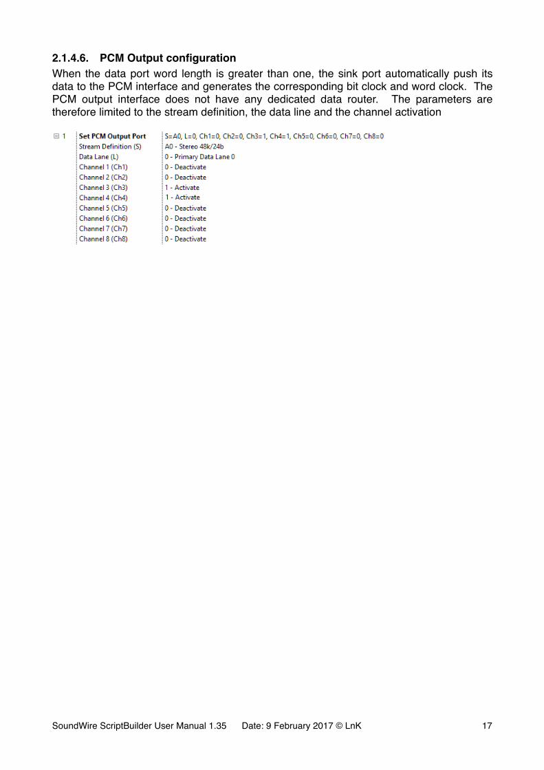
2.1.4.6. PCM Output configurationWhen the data port word length is greater than one, the sink port automatically push its data to the PCM interface and generates the corresponding bit clock and word clock. The PCM output interface does not have any dedicated data router. The parameters are therefore limited to the stream definition, the data line and the channel activation
�
SoundWire ScriptBuilder User Manual 1.35 Date: 9 February 2017 © LnK �17
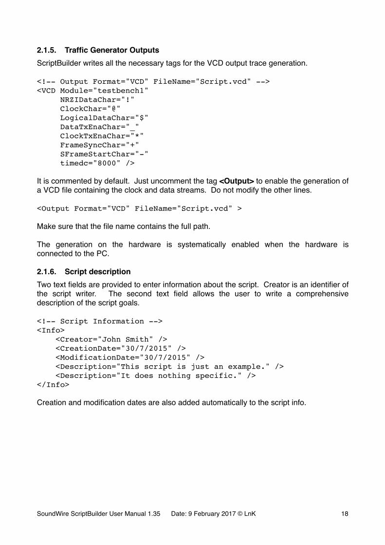
2.1.5. Traffic Generator OutputsScriptBuilder writes all the necessary tags for the VCD output trace generation.
<!-- Output Format="VCD" FileName="Script.vcd" --><VCD Module="testbench1" NRZIDataChar="!" ClockChar="@" LogicalDataChar="$" DataTxEnaChar="_" ClockTxEnaChar="*" FrameSyncChar="+" SFrameStartChar="-" timedc="8000" />
It is commented by default. Just uncomment the tag <Output> to enable the generation of a VCD file containing the clock and data streams. Do not modify the other lines.
<Output Format="VCD" FileName="Script.vcd" >
Make sure that the file name contains the full path.
The generation on the hardware is systematically enabled when the hardware is connected to the PC.
2.1.6. Script descriptionTwo text fields are provided to enter information about the script. Creator is an identifier of the script writer. The second text field allows the user to write a comprehensive description of the script goals.
<!-- Script Information --><Info> <Creator="John Smith" /> <CreationDate="30/7/2015" /> <ModificationDate="30/7/2015" /> <Description="This script is just an example." /> <Description="It does nothing specific." /></Info>
Creation and modification dates are also added automatically to the script info.
SoundWire ScriptBuilder User Manual 1.35 Date: 9 February 2017 © LnK �18
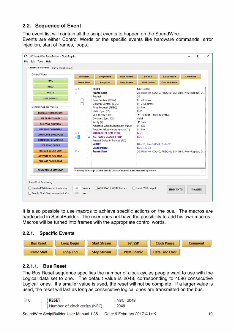
2.2. Sequence of EventThe event list will contain all the script events to happen on the SoundWire.Events are either Control Words or the specific events like hardware commands, error injection, start of frames, loops...
�
It is also possible to use macros to achieve specific actions on the bus. The macros are hardcoded in ScriptBuilder. The user does not have the possibility to add his own macros.Macros will be turned into frames with the appropriate control words.
2.2.1. Specific Events
�
2.2.1.1. Bus ResetThe Bus Reset sequence specifies the number of clock cycles people want to use with the Logical data set to one. The default value is 2048, corresponding to 4096 consecutive Logical ones. If a smaller value is used, the reset will not be complete. If a larger value is used, the reset will last as long as consecutive logical ones are transmitted on the bus.
�SoundWire ScriptBuilder User Manual 1.35 Date: 9 February 2017 © LnK �19
In normal situation, the parameter of the Bus Reset sequence should not be modified.
XML Translation:
The XML tag is <Reset>. The parameter is Nbc, the number of clock cycles.
<!-- Event #0 : RESET --><Reset Nbc="2048" />
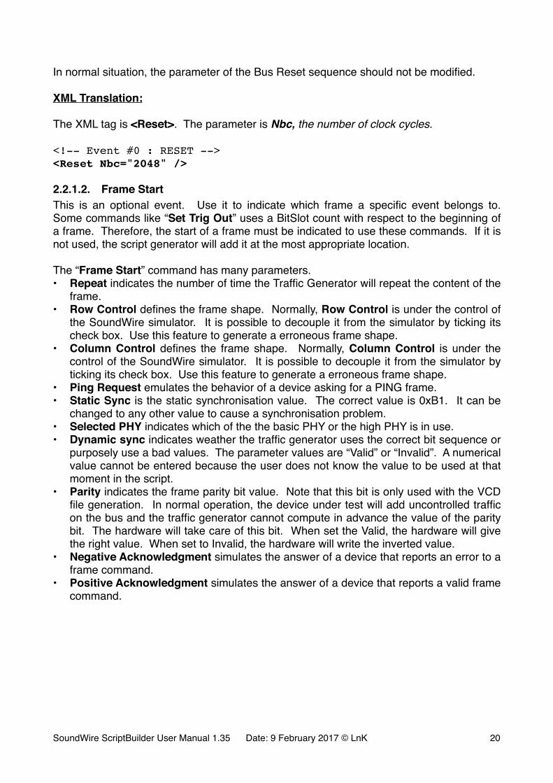
2.2.1.2. Frame StartThis is an optional event. Use it to indicate which frame a specific event belongs to. Some commands like “Set Trig Out” uses a BitSlot count with respect to the beginning of a frame. Therefore, the start of a frame must be indicated to use these commands. If it is not used, the script generator will add it at the most appropriate location.
The “Frame Start” command has many parameters.• Repeat indicates the number of time the Traffic Generator will repeat the content of the
frame.• Row Control defines the frame shape. Normally, Row Control is under the control of
the SoundWire simulator. It is possible to decouple it from the simulator by ticking its check box. Use this feature to generate a erroneous frame shape.
• Column Control defines the frame shape. Normally, Column Control is under the control of the SoundWire simulator. It is possible to decouple it from the simulator by ticking its check box. Use this feature to generate a erroneous frame shape.
• Ping Request emulates the behavior of a device asking for a PING frame.• Static Sync is the static synchronisation value. The correct value is 0xB1. It can be
changed to any other value to cause a synchronisation problem.• Selected PHY indicates which of the the basic PHY or the high PHY is in use.• Dynamic sync indicates weather the traffic generator uses the correct bit sequence or
purposely use a bad values. The parameter values are “Valid” or “Invalid”. A numerical value cannot be entered because the user does not know the value to be used at that moment in the script.
• Parity indicates the frame parity bit value. Note that this bit is only used with the VCD file generation. In normal operation, the device under test will add uncontrolled traffic on the bus and the traffic generator cannot compute in advance the value of the parity bit. The hardware will take care of this bit. When set the Valid, the hardware will give the right value. When set to Invalid, the hardware will write the inverted value.
• Negative Acknowledgment simulates the answer of a device that reports an error to a frame command.
• Positive Acknowledgment simulates the answer of a device that reports a valid frame command.
SoundWire ScriptBuilder User Manual 1.35 Date: 9 February 2017 © LnK �20
�
Note 1: The little black arrows on the right side indicates when a value can only be changed by the use of a contextual menu (mouse right click).
Note 2: A SoundWire frame has always a control word. If the control word is omitted by the user, ScriptBuilder will automatically insert a PING control word.
XML Translation:
The TAG is <Swframe parameter=“xxx” > … </Swframe>. The parameters are Repeat, rows, cols, preq, StaticSync, Phy, DynamicSync, Parity, nak and ack.The frame is a container for other events to happen during that frame.
<!-- Event #0 : Frame Start --><Swframe Repeat="1" rows="48" cols="2" preq="0" StaticSync=“177" Phy="0" DynamicSync="Valid" Parity="Valid" nak="0" ack="0" > <!-- Event #1 : PING --> <controlword opcode="0" breq="0" ssp="0" brel="0" reserved="0" /></Swframe>
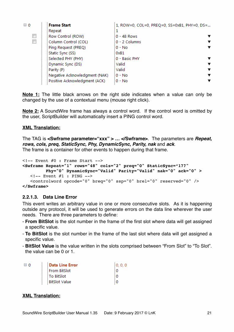
2.2.1.3. Data Line ErrorThis event writes an arbitrary value in one or more consecutive slots. As it is happening outside any protocol, it will be used to generate errors on the data line wherever the user needs. There are three parameters to define:- From BitSlot is the slot number in the frame of the first slot where data will get assigned
a specific value.- To BitSlot is the slot number in the frame of the last slot where data will get assigned a
specific value.- BitSlot Value is the value written in the slots comprised between “From Slot” to “To Slot”.
the value can be 0 or 1.
�
XML Translation:
SoundWire ScriptBuilder User Manual 1.35 Date: 9 February 2017 © LnK �21
The XML container is <Error>, the XML tag is <EData> and the parameters are StartSlot, EndSlot and Val.
<!-- Event #0 : Frame Start --><Swframe Repeat="1" rows="48" cols="2" preq="0" StaticSync="177" Phy=“0" DynamicSync="Auto" Parity="Valid" nak="0" ack="0" > <!-- Event #1 : Data Line Error --> <Error> <EData StartSlot="5" EndSlot="18" Val="1" /> </Error> <!-- Event #2 : PING --> <controlword opcode="0" breq="0" ssp="0" brel="0" reserved="0" ></Swframe>
Note: this tag will always happen inside a frame container.
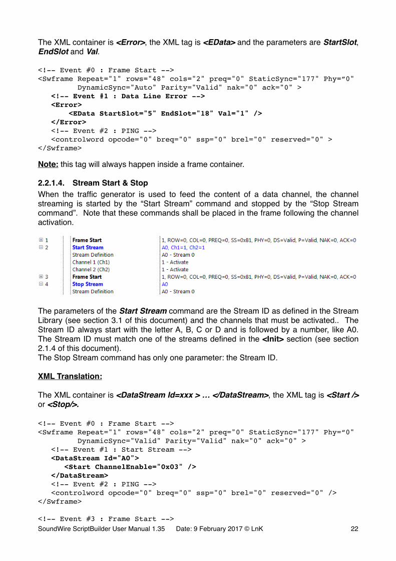
2.2.1.4. Stream Start & StopWhen the traffic generator is used to feed the content of a data channel, the channel streaming is started by the “Start Stream” command and stopped by the “Stop Stream command”. Note that these commands shall be placed in the frame following the channel activation.
�
The parameters of the Start Stream command are the Stream ID as defined in the Stream Library (see section 3.1 of this document) and the channels that must be activated.. The Stream ID always start with the letter A, B, C or D and is followed by a number, like A0. The Stream ID must match one of the streams defined in the <Init> section (see section 2.1.4 of this document).The Stop Stream command has only one parameter: the Stream ID.
XML Translation:
The XML container is <DataStream Id=xxx > … </DataStream>, the XML tag is <Start /> or <Stop/>.
<!-- Event #0 : Frame Start --><Swframe Repeat="1" rows="48" cols="2" preq="0" StaticSync="177" Phy=“0" DynamicSync="Valid" Parity="Valid" nak="0" ack="0" > <!-- Event #1 : Start Stream --> <DataStream Id="A0"> <Start ChannelEnable="0x03" /> </DataStream> <!-- Event #2 : PING --> <controlword opcode="0" breq="0" ssp="0" brel="0" reserved="0" /></Swframe> <!-- Event #3 : Frame Start -->SoundWire ScriptBuilder User Manual 1.35 Date: 9 February 2017 © LnK �22
<Swframe Repeat="1" rows="48" cols="2" preq="0" StaticSync="177" Phy=“0" DynamicSync="Valid" Parity="Valid" nak="0" ack="0" > <!-- Event #4 : Stop Stream --> <DataStream Id="A0"> <Stop/> </DataStream> <!-- Event #5 : PING --> <controlword opcode="0" breq="0" ssp="0" brel="0" reserved="0" /></Swframe>
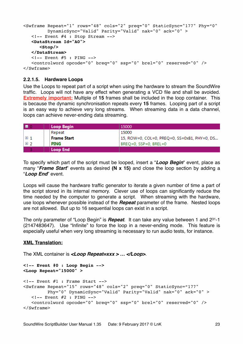
2.2.1.5. Hardware LoopsUse the Loops to repeat part of a script when using the hardware to stream the SoundWire traffic. Loops will not have any effect when generating a VCD file and shall be avoided. Extremely important: Multiple of 15 frames shall be included in the loop container. This is because the dynamic synchronisation repeats every 15 frames. Looping part of a script is an easy way to achieve very long streams. When streaming data in a data channel, loops can achieve never-ending data streaming.
�
To specify which part of the script must be looped, insert a “Loop Begin“ event, place as many “Frame Start” events as desired (N x 15) and close the loop section by adding a “Loop End” event.
Loops will cause the hardware traffic generator to iterate a given number of time a part of the script stored in its internal memory. Clever use of loops can significantly reduce the time needed by the computer to generate a script. When streaming with the hardware, use loops whenever possible instead of the Repeat parameter of the frame. Nested loops are not allowed. But up to 16 sequential loops can exist in a script.
The only parameter of “Loop Begin” is Repeat. It can take any value between 1 and 231-1 (2147483647). Use “Infinite” to force the loop in a never-ending mode. This feature is especially useful when very long streaming is necessary to run audio tests, for instance.
XML Translation:
The XML container is <Loop Repeat=xxx > … </Loop>.
<!-- Event #0 : Loop Begin --><Loop Repeat="15000" > <!-- Event #1 : Frame Start --><Swframe Repeat="15" rows="48" cols="2" preq="0" StaticSync=“177" Phy="0" DynamicSync="Valid" Parity="Valid" nak="0" ack="0" > <!-- Event #2 : PING --> <controlword opcode="0" breq="0" ssp="0" brel="0" reserved="0" /></Swframe>
SoundWire ScriptBuilder User Manual 1.35 Date: 9 February 2017 © LnK �23
<!-- Event #3 : Loop End --></Loop>
2.2.1.6. Set SSPUse the command “Set SSP” to define the period of appearance of the SSP bits in PING frames. The command has one parameter, Period, which defines the period of appearance (in frames) of the SSP bit in the PING commands.In order to be able to control individually the SSP bits, the command will cause any subsequent Frame Start event with a Repeat parameter equal to N to appear as N times a Frames Start event with a repeat parameter equal to 1.
Set SSP is so far then only command that does not have a direct XML translation as its effect propagates through the entire script.
The command must have its own Frame Start container.
If Set SSP is located in Frame M, the SSP bit will be first set in Frame M+Period.For convenience, a Set SSP command has been embedded in the SET FRAME SHAPE macro, making the configuration of SSP bits at channel activation quite simple.
The data ports of the analyzer are activated by the presence of a SSP bit. Without that bit being present, the outputs of the data port will stay muted. Note that one frame with a SSP bit set is sufficient.
2.2.1.7. PDM EnableThis command is used to activate (or deactivate) the HW PDM / PCM interface. The port parameters are defined in the traffic initialization section. The PDM Enable command will activate both PDM / PCM input and PDM / PCM output interface. The command parameter can get 2 values: 0 means PDM / PCM HW interface disabled, 1 means PDM / PCM HW interface enabled.For proper SoundWire operation, enable the PDM / PCM interface after the DUT data ports are activated, in the Frame Start event following a SET FRAME SHAPE macro, for instance. Don’t forget to set the SSP bit on an appropriate period.
XML Translation:
The XML tag is <PDM Enable=“x”/>. The parameter is Enable. The tag is necessarily located in a Swframe container.
<!-- Event #13 : Frame Start --><Swframe Repeat="1" rows="48" cols="16" preq="0" StaticSync="177" Phy="0" DynamicSync="Valid" Parity="Valid" nak="0" ack="0" > <!-- Event #14 : PING --> <controlword opcode="0" ssp="0" breq="0" brel="0" reserved="0" /> <!-- Event #15 : PDM Enable --> <PDM Enable="1" /></Swframe>
2.2.1.8. Clock PauseThis command is used to pause the SoundWire bus clock. The command has two parameters: Restart Delay, which specifies the number of frames during which the clock SoundWire ScriptBuilder User Manual 1.35 Date: 9 February 2017 © LnK �24
will be held low and Stopping Frame which specifies if a stopping frame must be inserted before stopping the clock. The clock automatically resume after the Restart delay. Wake-up by slave is not supported yet.
Note that the line level at the end of the stopping frame can be either HIGH or LOW. The level won’t be parked at a LOW level during the pause period. This will not have any adverse effects on the Device Under Test (DUT).
XML Translation:
The XML tag is <ClockPause Restart=“x” Stopping=“0” />. The parameters are Restart and Stopping.
<!-- Event #15 : Clock Pause --><ClockPause Restart=“1024” Stopping="0"/>
SoundWire ScriptBuilder User Manual 1.35 Date: 9 February 2017 © LnK �25
2.2.2. Control WordsSoundWire uses 3 control words to control the devices attached to the bus: PING, READ and WRITE. ScriptBuilder also allows the user to transmit reserved control words opcode with arbitrary parameter values.
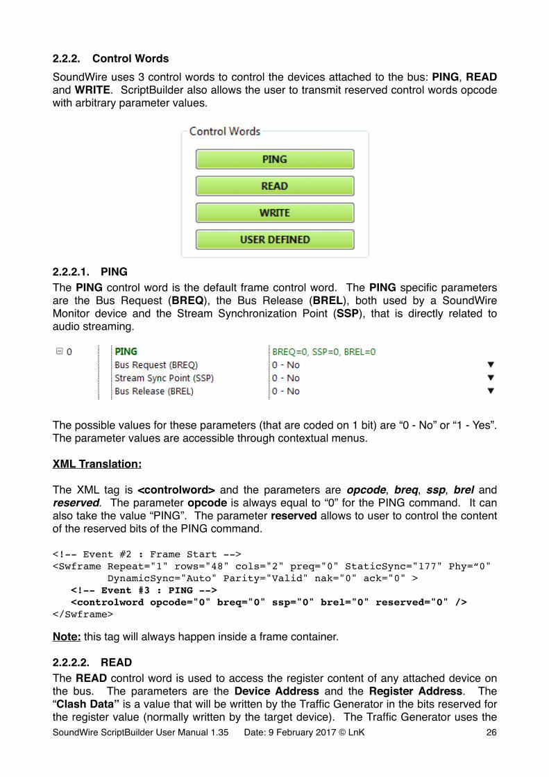
�2.2.2.1. PINGThe PING control word is the default frame control word. The PING specific parameters are the Bus Request (BREQ), the Bus Release (BREL), both used by a SoundWire Monitor device and the Stream Synchronization Point (SSP), that is directly related to audio streaming.
�
The possible values for these parameters (that are coded on 1 bit) are “0 - No” or “1 - Yes”. The parameter values are accessible through contextual menus.
XML Translation:
The XML tag is <controlword> and the parameters are opcode, breq, ssp, brel and reserved. The parameter opcode is always equal to “0” for the PING command. It can also take the value “PING”. The parameter reserved allows to user to control the content of the reserved bits of the PING command.
<!-- Event #2 : Frame Start --><Swframe Repeat="1" rows="48" cols="2" preq="0" StaticSync="177" Phy=“0" DynamicSync="Auto" Parity="Valid" nak="0" ack="0" > <!-- Event #3 : PING --> <controlword opcode="0" breq="0" ssp="0" brel="0" reserved="0" /></Swframe>
Note: this tag will always happen inside a frame container.
2.2.2.2. READThe READ control word is used to access the register content of any attached device on the bus. The parameters are the Device Address and the Register Address. The “Clash Data” is a value that will be written by the Traffic Generator in the bits reserved for the register value (normally written by the target device). The Traffic Generator uses the SoundWire ScriptBuilder User Manual 1.35 Date: 9 February 2017 © LnK �26
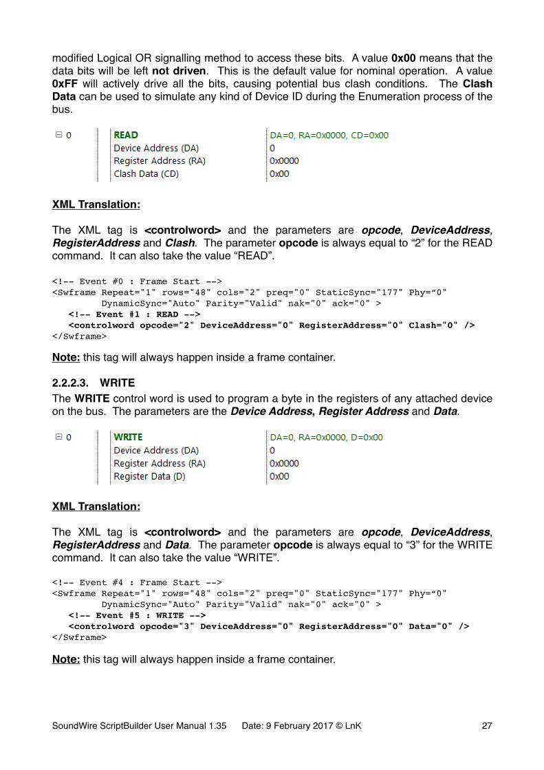
modified Logical OR signalling method to access these bits. A value 0x00 means that the data bits will be left not driven. This is the default value for nominal operation. A value 0xFF will actively drive all the bits, causing potential bus clash conditions. The Clash Data can be used to simulate any kind of Device ID during the Enumeration process of the bus.
�
XML Translation:
The XML tag is <controlword> and the parameters are opcode, DeviceAddress, RegisterAddress and Clash. The parameter opcode is always equal to “2” for the READ command. It can also take the value “READ”.
<!-- Event #0 : Frame Start --><Swframe Repeat="1" rows="48" cols="2" preq="0" StaticSync="177" Phy=“0" DynamicSync="Auto" Parity="Valid" nak="0" ack="0" > <!-- Event #1 : READ --> <controlword opcode="2" DeviceAddress="0" RegisterAddress="0" Clash="0" /></Swframe>
Note: this tag will always happen inside a frame container.
2.2.2.3. WRITEThe WRITE control word is used to program a byte in the registers of any attached device on the bus. The parameters are the Device Address, Register Address and Data.
�
XML Translation:
The XML tag is <controlword> and the parameters are opcode, DeviceAddress, RegisterAddress and Data. The parameter opcode is always equal to “3” for the WRITE command. It can also take the value “WRITE”.
<!-- Event #4 : Frame Start --><Swframe Repeat="1" rows="48" cols="2" preq="0" StaticSync="177" Phy=“0" DynamicSync="Auto" Parity="Valid" nak="0" ack="0" > <!-- Event #5 : WRITE --> <controlword opcode="3" DeviceAddress="0" RegisterAddress="0" Data="0" /></Swframe>
Note: this tag will always happen inside a frame container.
SoundWire ScriptBuilder User Manual 1.35 Date: 9 February 2017 © LnK �27
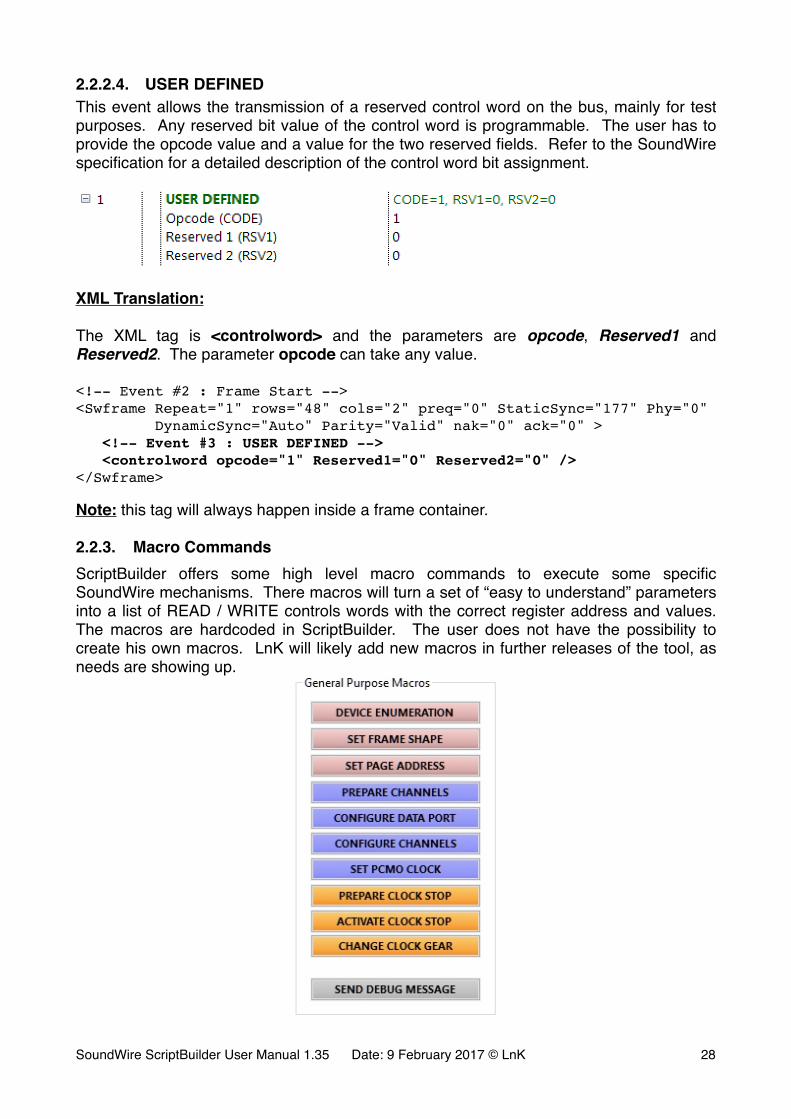
2.2.2.4. USER DEFINEDThis event allows the transmission of a reserved control word on the bus, mainly for test purposes. Any reserved bit value of the control word is programmable. The user has to provide the opcode value and a value for the two reserved fields. Refer to the SoundWire specification for a detailed description of the control word bit assignment.
�
XML Translation:
The XML tag is <controlword> and the parameters are opcode, Reserved1 and Reserved2. The parameter opcode can take any value.
<!-- Event #2 : Frame Start --><Swframe Repeat="1" rows="48" cols="2" preq="0" StaticSync="177" Phy="0" DynamicSync="Auto" Parity="Valid" nak="0" ack="0" > <!-- Event #3 : USER DEFINED --> <controlword opcode="1" Reserved1="0" Reserved2="0" /></Swframe>
Note: this tag will always happen inside a frame container.
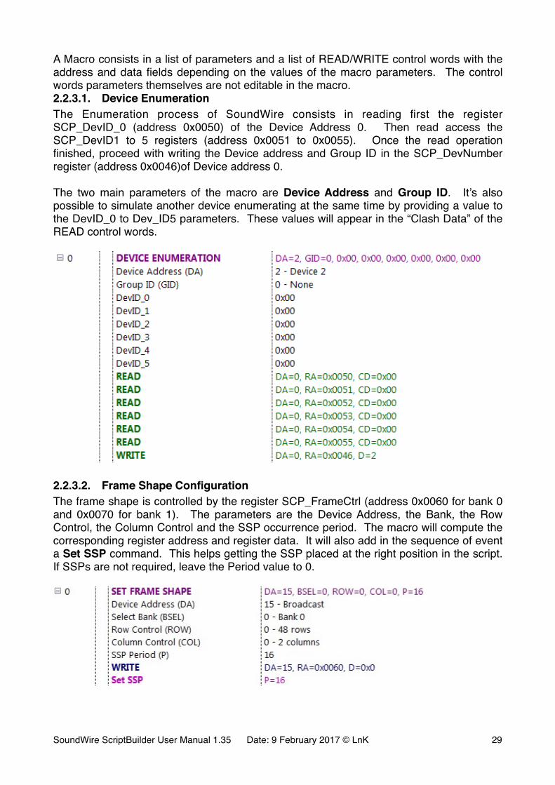
2.2.3. Macro CommandsScriptBuilder offers some high level macro commands to execute some specific SoundWire mechanisms. There macros will turn a set of “easy to understand” parameters into a list of READ / WRITE controls words with the correct register address and values. The macros are hardcoded in ScriptBuilder. The user does not have the possibility to create his own macros. LnK will likely add new macros in further releases of the tool, as needs are showing up.
�
SoundWire ScriptBuilder User Manual 1.35 Date: 9 February 2017 © LnK �28
A Macro consists in a list of parameters and a list of READ/WRITE control words with the address and data fields depending on the values of the macro parameters. The control words parameters themselves are not editable in the macro.2.2.3.1. Device EnumerationThe Enumeration process of SoundWire consists in reading first the register SCP_DevID_0 (address 0x0050) of the Device Address 0. Then read access the SCP_DevID1 to 5 registers (address 0x0051 to 0x0055). Once the read operation finished, proceed with writing the Device address and Group ID in the SCP_DevNumber register (address 0x0046)of Device address 0.
The two main parameters of the macro are Device Address and Group ID. It’s also possible to simulate another device enumerating at the same time by providing a value to the DevID_0 to Dev_ID5 parameters. These values will appear in the “Clash Data” of the READ control words.
�
2.2.3.2. Frame Shape ConfigurationThe frame shape is controlled by the register SCP_FrameCtrl (address 0x0060 for bank 0 and 0x0070 for bank 1). The parameters are the Device Address, the Bank, the Row Control, the Column Control and the SSP occurrence period. The macro will compute the corresponding register address and register data. It will also add in the sequence of event a Set SSP command. This helps getting the SSP placed at the right position in the script. If SSPs are not required, leave the Period value to 0.
�
SoundWire ScriptBuilder User Manual 1.35 Date: 9 February 2017 © LnK �29
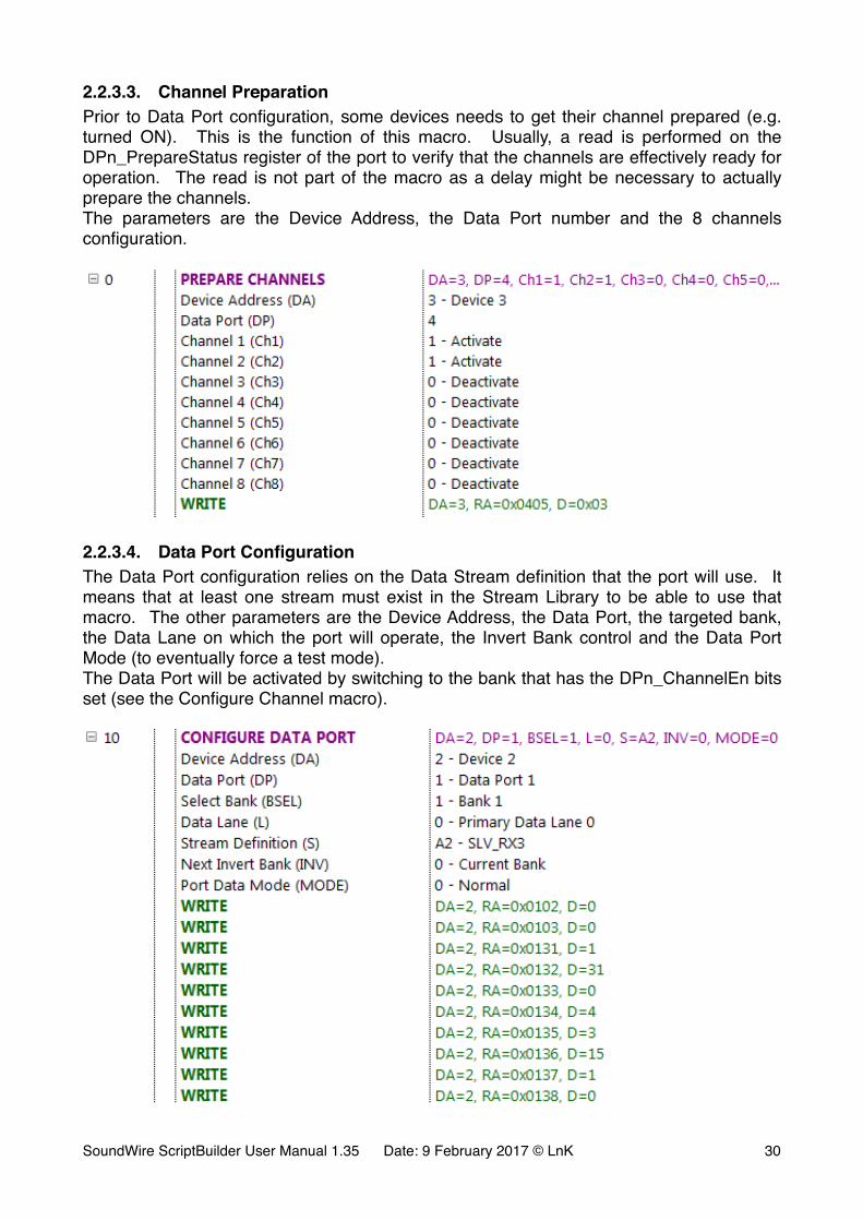
2.2.3.3. Channel PreparationPrior to Data Port configuration, some devices needs to get their channel prepared (e.g. turned ON). This is the function of this macro. Usually, a read is performed on the DPn_PrepareStatus register of the port to verify that the channels are effectively ready for operation. The read is not part of the macro as a delay might be necessary to actually prepare the channels.The parameters are the Device Address, the Data Port number and the 8 channels configuration.
�
2.2.3.4. Data Port ConfigurationThe Data Port configuration relies on the Data Stream definition that the port will use. It means that at least one stream must exist in the Stream Library to be able to use that macro. The other parameters are the Device Address, the Data Port, the targeted bank, the Data Lane on which the port will operate, the Invert Bank control and the Data Port Mode (to eventually force a test mode).The Data Port will be activated by switching to the bank that has the DPn_ChannelEn bits set (see the Configure Channel macro).
�
SoundWire ScriptBuilder User Manual 1.35 Date: 9 February 2017 © LnK �30
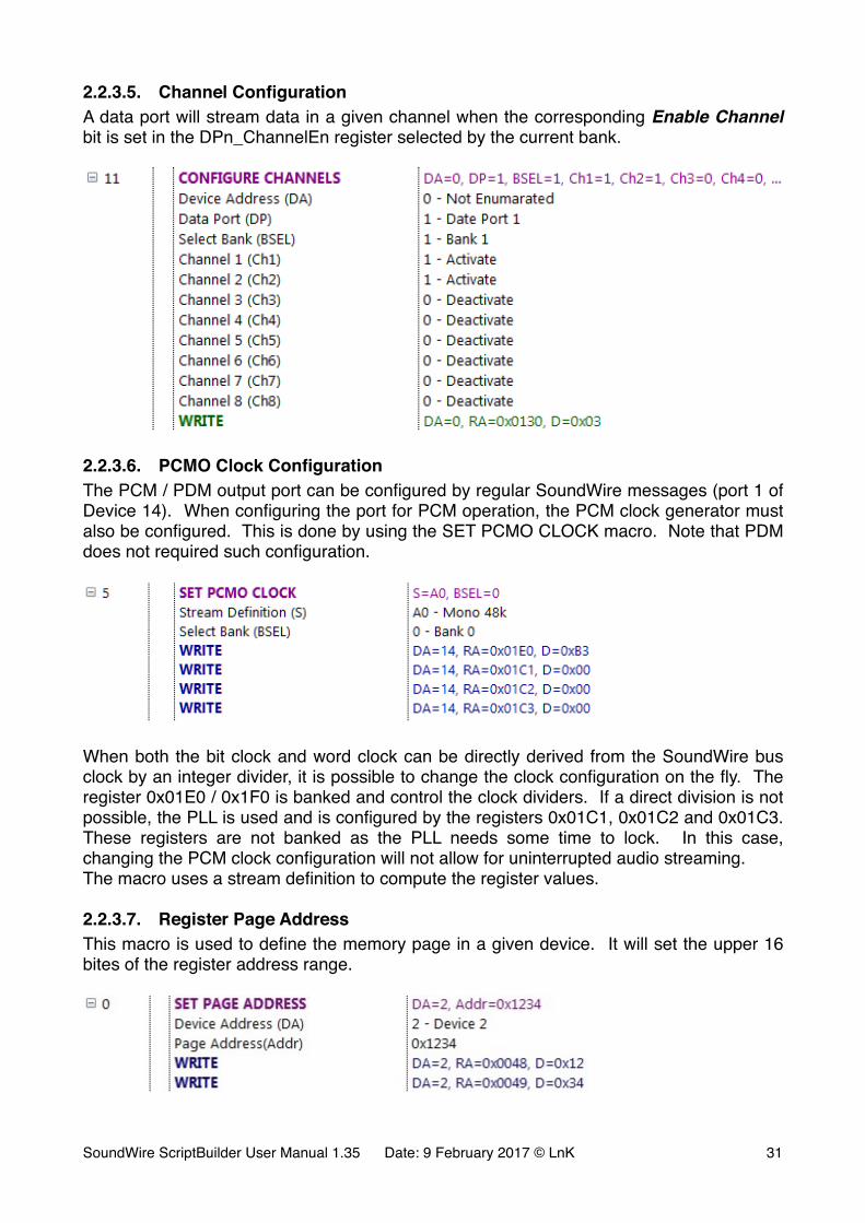
2.2.3.5. Channel ConfigurationA data port will stream data in a given channel when the corresponding Enable Channel bit is set in the DPn_ChannelEn register selected by the current bank.
�
2.2.3.6. PCMO Clock ConfigurationThe PCM / PDM output port can be configured by regular SoundWire messages (port 1 of Device 14). When configuring the port for PCM operation, the PCM clock generator must also be configured. This is done by using the SET PCMO CLOCK macro. Note that PDM does not required such configuration.
�
When both the bit clock and word clock can be directly derived from the SoundWire bus clock by an integer divider, it is possible to change the clock configuration on the fly. The register 0x01E0 / 0x1F0 is banked and control the clock dividers. If a direct division is not possible, the PLL is used and is configured by the registers 0x01C1, 0x01C2 and 0x01C3. These registers are not banked as the PLL needs some time to lock. In this case, changing the PCM clock configuration will not allow for uninterrupted audio streaming.The macro uses a stream definition to compute the register values.
2.2.3.7. Register Page AddressThis macro is used to define the memory page in a given device. It will set the upper 16 bites of the register address range.
�
SoundWire ScriptBuilder User Manual 1.35 Date: 9 February 2017 © LnK �31

2.2.3.8. Prepare clock stopUse this macro to advertise a clock stop event. Select the clock stop mode corresponding to the test case: Mode0 (for a soft stop with activity resume on wake-up) or Mode1 (for a deep sleep with device reset on wake-up).
�
2.2.3.9. Activate clock stopUse this macro after the PREPARE CLOCK STOP command. It will put the devices into sleep and will generate a stopping frame. The bus will automatically wake-up after a restart delay given in frames.
�The clock can be resumed automatically after a defined delay, manually restarted from the traffic generator panel or restarted by the device under test, according to the SoundWire specification.
�
2.2.3.10. Change Clock GearThis macro allows for dynamic bus clock frequency change. The bus clock can be divided by an integer value ranging from 1 to 16, 1 corresponding to the nominal bus clock frequency.
�
The clock frequency transition happens at the beginning of the frame following a write access to the SCP_FrameCtrl (either 0x0060 or 0x0070). The typical use case is to modify the bus clock and the sample interval accordingly in order to maintain the same sample rate. This is done through bank switch and the clock frequency change is time aligned with the bank switch.
Note: When booting with a clock gear, the actual value the the 0x01C4 register is still 1. A the first access of SCP_FrameCtrl, the bus frequency will jump back to nominal. If this behavior is not desired, a CHANGE CLOCK GEAR macro must be inserted before the first SCP_FrameCtrl access and programmed with the BOOT clock gear.
2.2.3.11. Debug Message TransmissionThis macro is a specific debug tool designed to transmit a full text message to the Protocol Analyzer during the script execution. When the analyzer decodes a WRITE control word with a specific Device Address and Register Address, it will look at the written data and SoundWire ScriptBuilder User Manual 1.35 Date: 9 February 2017 © LnK �32
match a corresponding text string in a look-up table. Obviously, the user must make sure that the combination Device / Register is not in use in the setup he is testing.
Text strings are defined in files: lnk.msg is provided by default. (located in the C:/LnK/SoundWire/project directory) lnk.msg contains some tools defined strings corresponding to the Device Address 14, Register Address 0x00FF. Up to 255 strings can be defined in one message file. The user has the possibility to generate as many .msg files he needs but only one at a time can be used.
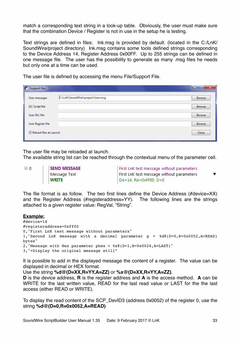
The user file is defined by accessing the menu File/Support File.
�
The user file may be reloaded at launch.The available string list can be reached through the contextual menu of the parameter cell.
�
The file format is as follow. The two first lines define the Device Address (#device=XX) and the Register Address (#registeraddress=YY). The following lines are the strings attached to a given register value: RegVal, “String”.
Example:#device=14#registeraddress=0xff000,"First LnK test message without parameters"1,"Second LnK message with a decimal parameter p = %d@(D=0,R=0x0052,A=READ) bytes"2,"Message with Hex parameter phex = %x@(D=1,R=0x0024,A=LAST)"3,"+Display the original message still”
It is possible to add in the displayed message the content of a register. The value can be displayed in decimal or HEX format.Use the string %d@(D=XX,R=YY,A=ZZ) or %x@(D=XX,R=YY,A=ZZ).D is the device address, R is the register address and A is the access method. A can be WRITE for the last written value, READ for the last read value or LAST for the the last access (either READ or WRITE).
To display the read content of the SCP_DevID3 (address 0x0052) of the register 0, use the string %d@(D=0,R=0x0052,A=READ)
SoundWire ScriptBuilder User Manual 1.35 Date: 9 February 2017 © LnK �33
If the sign “+” is placed in front of the string, the WRITE control word that triggers the string display is also shown.
2.3. XML Script GenerationThe event list only contains a script prototype. The user will only insert the significant events in the event list. It is always possible to manually add all the “Frame Start” and PING control words but this would actually be quite inefficient.
An isolated control word will systematically be understood as being a “Frame Start” event plus the control word itself. A “Frame Start” event without a control word will automatically get appended a PING control word and so on…
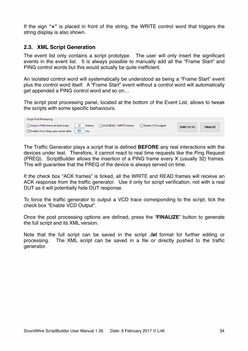
The script post processing panel, located at the bottom of the Event List, allows to tweak the scripts with some specific behaviours.
�
The Traffic Generator plays a script that is defined BEFORE any real interactions with the devices under test. Therefore, it cannot react to real time requests like the Ping Request (PREQ). ScriptBuilder allows the insertion of a PING frame every X (usually 32) frames. This will guarantee that the PREQ of the device is always served on time.
If the check box “ACK frames” is ticked, all the WRITE and READ frames will receive an ACK response from the traffic generator. Use it only for script verification, not with a real DUT as it will potentially hide DUT response.
To force the traffic generator to output a VCD trace corresponding to the script, tick the check box “Enable VCD Output”.
Once the post processing options are defined, press the “FINALIZE” button to generate the full script and its XML version.
Note that the full script can be saved in the script .lst format for further editing or processing. The XML script can be saved in a file or directly pushed to the traffic generator.
SoundWire ScriptBuilder User Manual 1.35 Date: 9 February 2017 © LnK �34
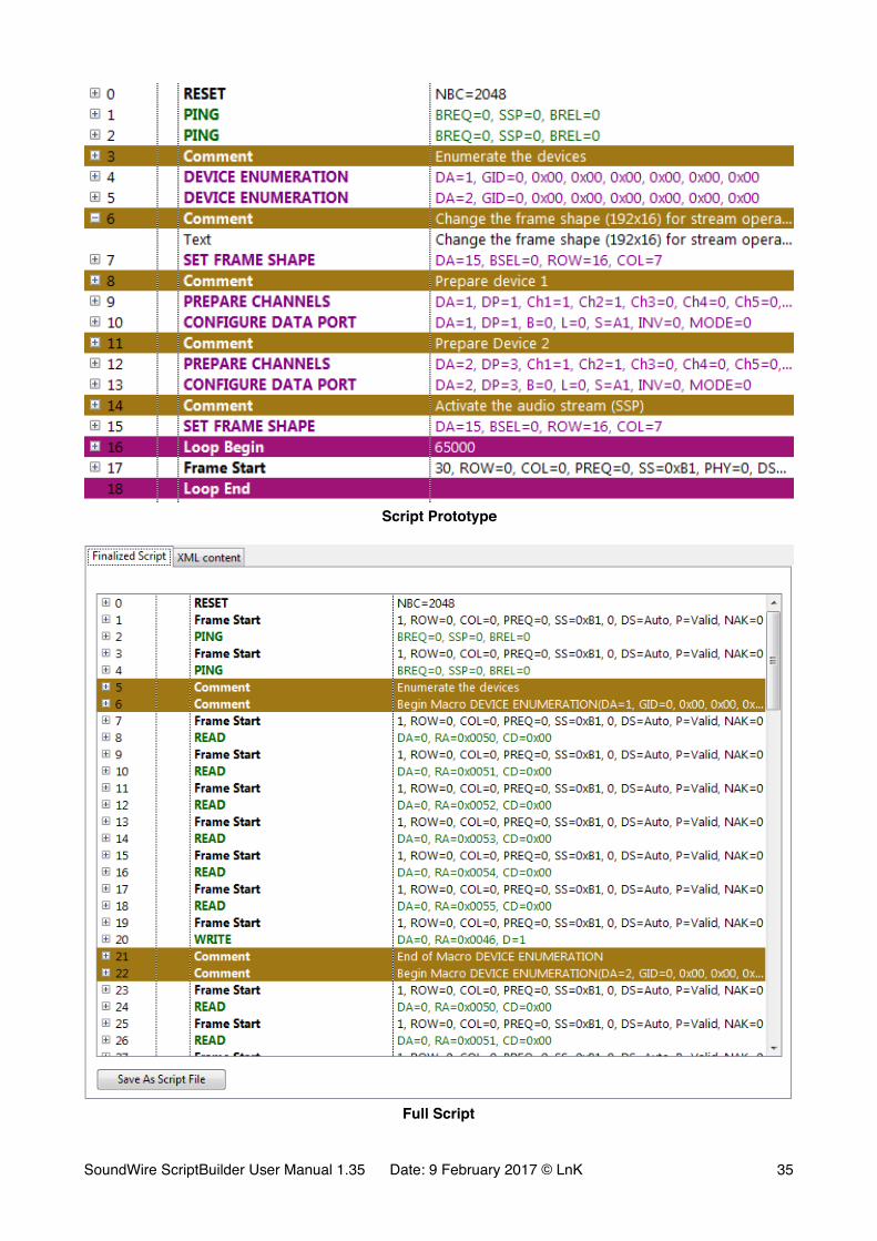
�Script Prototype
�Full Script
SoundWire ScriptBuilder User Manual 1.35 Date: 9 February 2017 © LnK �35
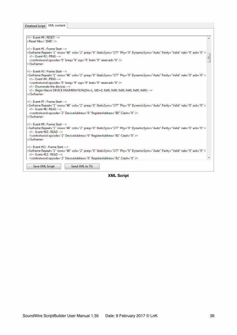
�XML Script
SoundWire ScriptBuilder User Manual 1.35 Date: 9 February 2017 © LnK �36
3. Additional Features
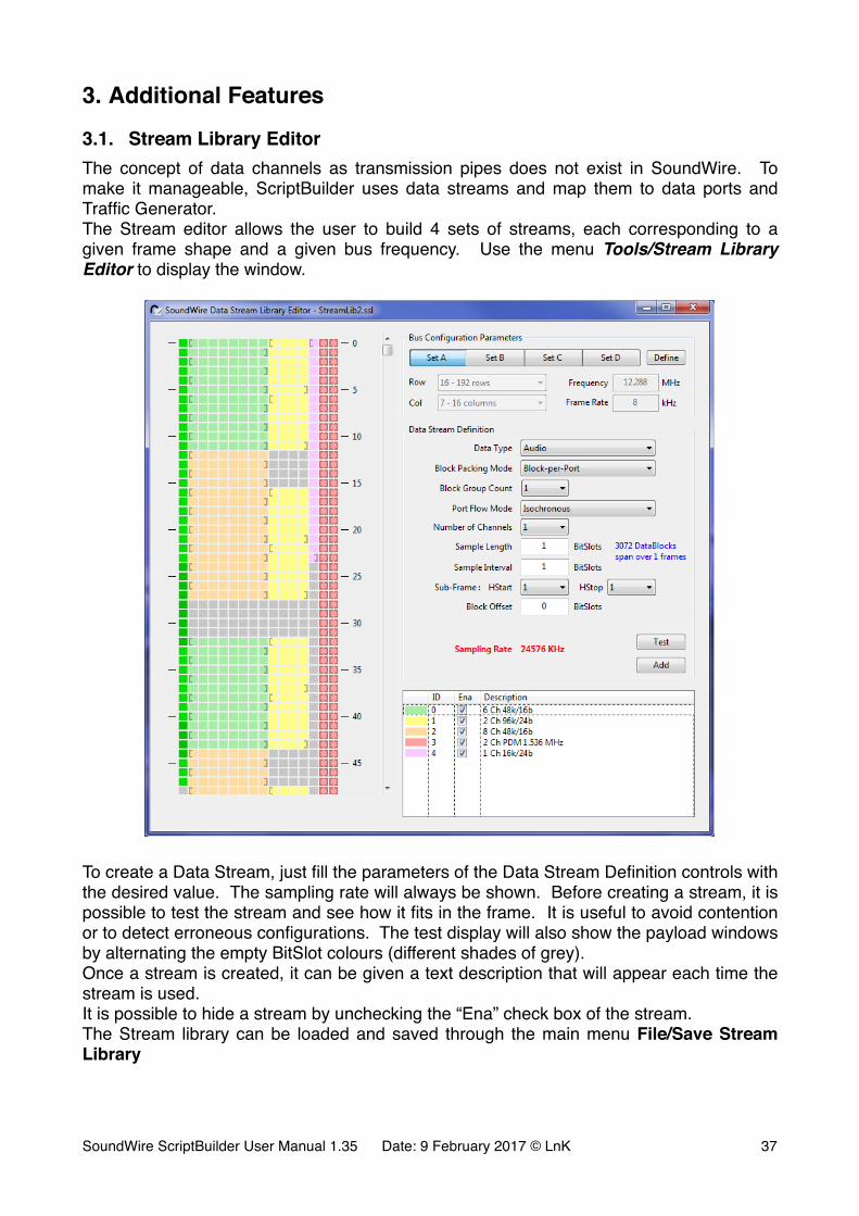
3.1. Stream Library EditorThe concept of data channels as transmission pipes does not exist in SoundWire. To make it manageable, ScriptBuilder uses data streams and map them to data ports and Traffic Generator.The Stream editor allows the user to build 4 sets of streams, each corresponding to a given frame shape and a given bus frequency. Use the menu Tools/Stream Library Editor to display the window.
�
To create a Data Stream, just fill the parameters of the Data Stream Definition controls with the desired value. The sampling rate will always be shown. Before creating a stream, it is possible to test the stream and see how it fits in the frame. It is useful to avoid contention or to detect erroneous configurations. The test display will also show the payload windows by alternating the empty BitSlot colours (different shades of grey).Once a stream is created, it can be given a text description that will appear each time the stream is used.It is possible to hide a stream by unchecking the “Ena” check box of the stream.The Stream library can be loaded and saved through the main menu File/Save Stream Library
SoundWire ScriptBuilder User Manual 1.35 Date: 9 February 2017 © LnK �37
3.2. BTP / BRA Transaction DefinitionThe Traffic generator can handle multiple concurrent BTP/BRA transactions (Write and Read).
3.2.1. BRA transaction description fileEach transaction is defined by its own XML script file.
The container <BRA …. >…</BRA> specifies the content and the behaviour of a given transaction. It has many parameters that are describing in detail what shall happen inside the BRA blocks.
- Start indicates the register start address of the BRA transaction.
- NB indicates the number of bytes to be transmitted or read in the complete BRA transaction (200 kBytes for instance). NB can be omitted when you proceed with a WRITE. It will be defined automatically by the content of the transaction. However, you can specify NB, even for a WRITE. In this case, NB bytes will be used out of the given byte values. If NB is greater than the given value, the missing bytes will be 0 padded.
- NV is the number of consecutive valid BRA blocks (containing either a READ or a WRITE operation).
- NI is the number of consecutive idle BRA blocks. Together with NV, it allows you to insert a pause in the data transmission to let the DUT to digest the transferred data or have time to prepare for the next read access. The structure is always NV BRA blocks followed by NI idle BRA block. This structure repeats all over the BRA transaction. If you do not need to pause the transmission, just set NI=0 or omit it.
- BPB indicates the number of data bytes per BRA block you want to transport. The value can range from 1 to 502, depending on the Data Port 0 parameters. The script editor indicate the minimum amount of bytes that can be transmitted per frame (or BRA block) over a given data channel. However, this amount can change from frame to frame (thanks to the SoundWire channel setup) and it may me desirable to use the maximum bandwidth allowed by the channel. In this case, BPB can be set to “Auto” or just be omitted.
- CMD specifies the BRA transaction (Write, Read or Idle). If omitted, it will default to Write. Note that a “Read” BRA packet does not have a defined content. Therefore, NB must always be specified to let the software know about how many bytes must be read from the DUT. Use “Idle” when idle blocks need to be inserted between Read or Write transactions.
- SID specifies the device address which is the target of the BRA transaction. If it is omitted, the script editor set the value to 0 or to the last specified value.
There are two ways of specifying the register content inside the BRA container: a list of values and a reference to a file containing a list of value.
Use the container <ValueList> …</ValueList> to directly define the register values to be used. The container has no parameters.Use the tag <ValueFile File=“xxx” /> to specify the location of a file containing the register values. The software will accept text (.txt) and binary file (.bin). If a text file is SoundWire ScriptBuilder User Manual 1.35 Date: 9 February 2017 © LnK �38
provided, it must contain one register value per line. The binary file will be read byte by byte. If the file is generated from 16 bits or 32 bits values, pay attention to the endianness of tool that generated the binary file.
Here is an example of a BRA XML file describing a WRITE transaction, followed by 5 idle blocks and then a READ transaction. All in the same data channel.
<!-- Test file for BRA block parsing --><!-- Write blocks --><BRA Cmd="Write" NV="2" NI="1" BPB="3" SID="2" Start="0x12345678"> <ValueList> 0xED <!-- Comments in the register value list --> 0xD1 // comment on value itself 0xEA </ValueList> <ValueFile File="c:/LnK/SoundWire/BRA_REG.txt" /></BRA><!-- 5 Idle blocks --><BRA Cmd="Idle" NV="5"></BRA><!-- Read blocks --><BRA Cmd="Read" NV="3" NI="1" NB="200" Start="0x10000000"></BRA>
3.2.2. BRA Transaction ActivationThe activation of a BRA transaction requires multiple steps.
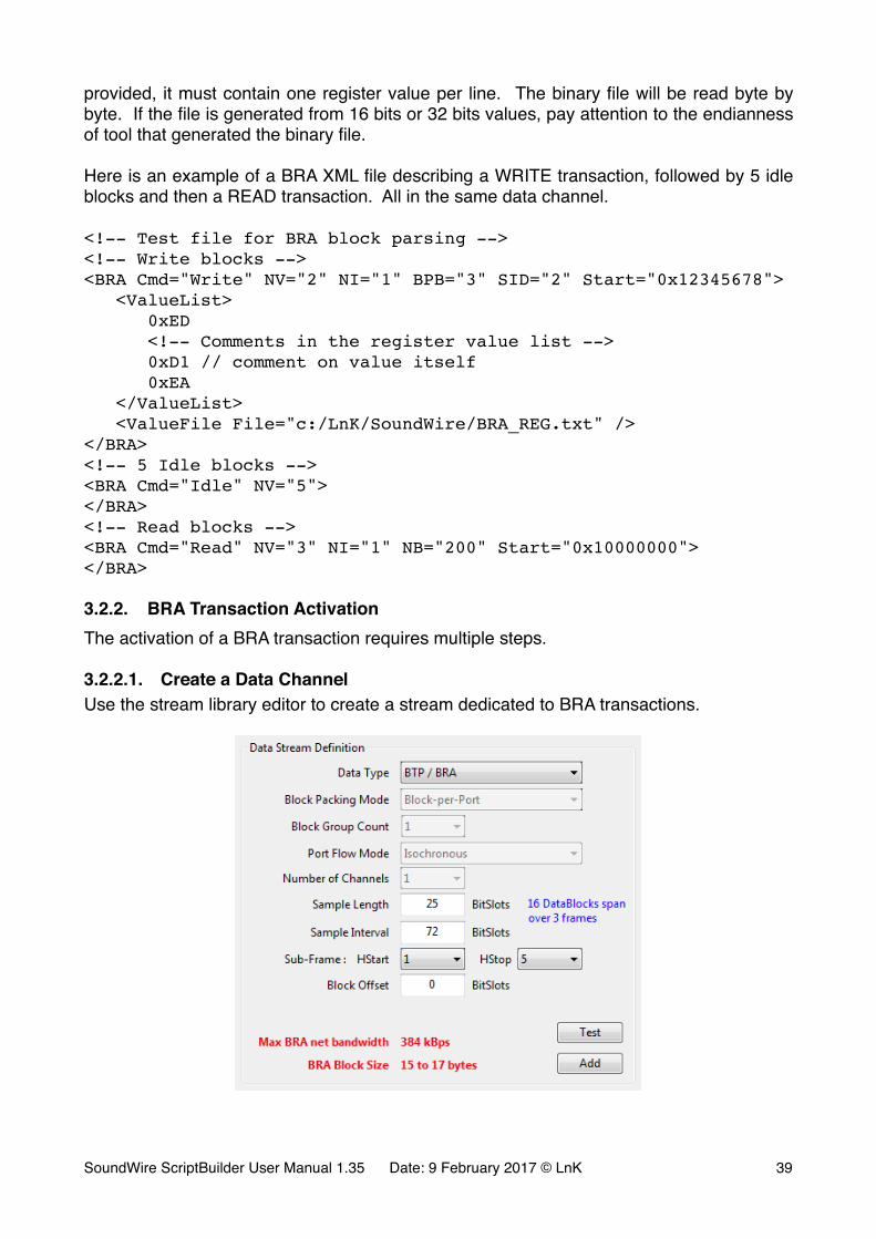
3.2.2.1. Create a Data ChannelUse the stream library editor to create a stream dedicated to BRA transactions.
�
SoundWire ScriptBuilder User Manual 1.35 Date: 9 February 2017 © LnK �39
• Select BTP / BRA in the data type scroll box. This will force the Block Packing Mode to Block-per-Port, the block Group Count to 1, the Port Flow Mode to Isochronous and the number of Channels to 1.
• Set the sample length and Sample interval to the desired value.• Define the sub-frame (HStart and HStop).• Eventually define a data block offset.
Once this is done, the software will show you the maximum net bandwidth of the channel and the possible BRA block sizes.
A BRA block has an overhead of 10 bytes (header, responses, CRCs & footer). This means that a BRA block must have at least a capacity of 11 bytes to be able to carry one data byte.
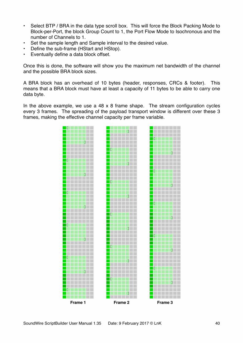
In the above example, we use a 48 x 8 frame shape. The stream configuration cycles every 3 frames. The spreading of the payload transport window is different over these 3 frames, making the effective channel capacity per frame variable.
� � �Frame 1 Frame 2 Frame 3
SoundWire ScriptBuilder User Manual 1.35 Date: 9 February 2017 © LnK �40

It is easy to see that the 3 frames do not carry the same number of bits in the channel. Frame 1 has 140 bits, frame 2 has 135 bits and frame 3 has 125 bits. A BRA block being byte based, frame 1 has 17 bytes, frame 2 has 16 bytes and frame 3 has 15 bytes. That’s what is shown by the software. The average amount of bytes over the 3 frames is equal to 16. With a bus clock of 12.288 MHz, the frame rate is equal to 64 kHz. The net bandwidth is equal to the number of average data bytes (16-10=6) times the frame rate: 6 bytes x 64 kHz = 384 kBytes/s.
With SoundWire, it is possible to define BRA channels that will have the required minimum amount of bytes only on some frames, some others not being able to transmit a block. Even though it is not a recommended configuration, it is valid. In this case, BRA blocks will only be fitted in frames capable of hosting them.
3.2.2.2. Define a Traffic Generator Channel ContentIn the Traffic Intialization tab of the main window, click on the “Add TG Stream” button to add an item in the list of the Data Stream Content Management. Expend it and fill the requested parameters.
�
Select the stream defined for the BRA transaction.Specify the data line on which it should appear.Specify the BRA XML file to be used to generate the data blocks appearing in the channel. For ease of use, right-click on the cell to get access to the Source Selector and browse for the desired xml file.
3.2.2.3. Data Port 0 ConfigurationIn the Sequence of Events, add a “CONFIGURE DATA PORT” macro. Expend it and set the parameters to the desired value (mainly device address, data port 0, bank and stream).
�
SoundWire ScriptBuilder User Manual 1.35 Date: 9 February 2017 © LnK �41
The Data Port 0 channel must be activated to start the transaction. In the example, this is done though bank switching. Bank 1 is configured and will be selected during the frame shape change.
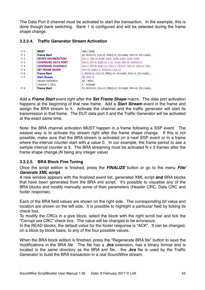
3.2.2.4. Traffic Generator Stream Activation
�
Add a Frame Start event right after the Set Frame Shape macro. The data port activation happens at the beginning of that new frame. Add a Start Stream event in the frame and assign the BRA stream to it. Activate the channel and the traffic generator will start its transmission in that frame. The DUT data port 0 and the Traffic Generator will be activated at the exact same time.
Note: the BRA channel activation MUST happen in a frame following a SSP event. The easiest way is to activate the stream right after the frame shape change. If this is not possible, make sure that the BRA stream is activated on a next SSP event or in a frame where the interval counter start with a value 0. In our example, the frame period to see a sample interval counter is 3. The BRA streaming must be activated N x 3 frames after the frame shape change.(N being any integer value)
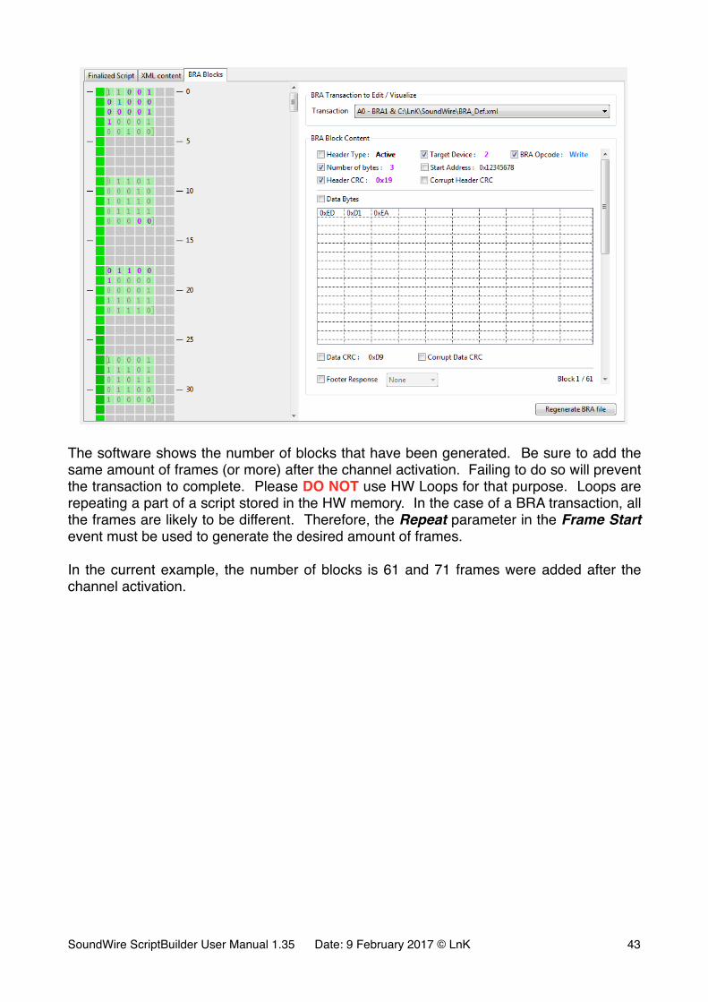
3.2.2.5. BRA Block Fine TuningOnce the script edition is finished, press the FINALIZE button or go to the menu File/Generate XML script.A new window appears with the finalized event list, generated XML script and BRA blocks that have been generated from the BRA xml script. It’s possible to visualise any of the BRA blocks and modify manually some of their parameters (Header CRC, Data CRC and footer response).
Each of the BRA field values are shown on the right side. The corresponding bit value and location are shown on the left side. It is possible to highlight a particular field by ticking its check box.To modify the CRCs in a give block, select the block with the right scroll bar and tick the “Corrupt xxx CRC” check box. The value will be changed to be erroneous.In the READ blocks, the default value for the footer response is “ACK”. It can be changed, on a block by block basis, to any of the four possible values.
When the BRA block edition is finished, press the “Regenerate BRA file” button to save the modifications in the BRA file. The file has a .bra extension, has a binary format and is located in the same directory as the BRA xml file. the .bra file is used by the Traffic Generator to build the BRA transaction in a real SoundWire stream.
SoundWire ScriptBuilder User Manual 1.35 Date: 9 February 2017 © LnK �42
�
The software shows the number of blocks that have been generated. Be sure to add the same amount of frames (or more) after the channel activation. Failing to do so will prevent the transaction to complete. Please DO NOT use HW Loops for that purpose. Loops are repeating a part of a script stored in the HW memory. In the case of a BRA transaction, all the frames are likely to be different. Therefore, the Repeat parameter in the Frame Start event must be used to generate the desired amount of frames.
In the current example, the number of blocks is 61 and 71 frames were added after the channel activation.
SoundWire ScriptBuilder User Manual 1.35 Date: 9 February 2017 © LnK �43
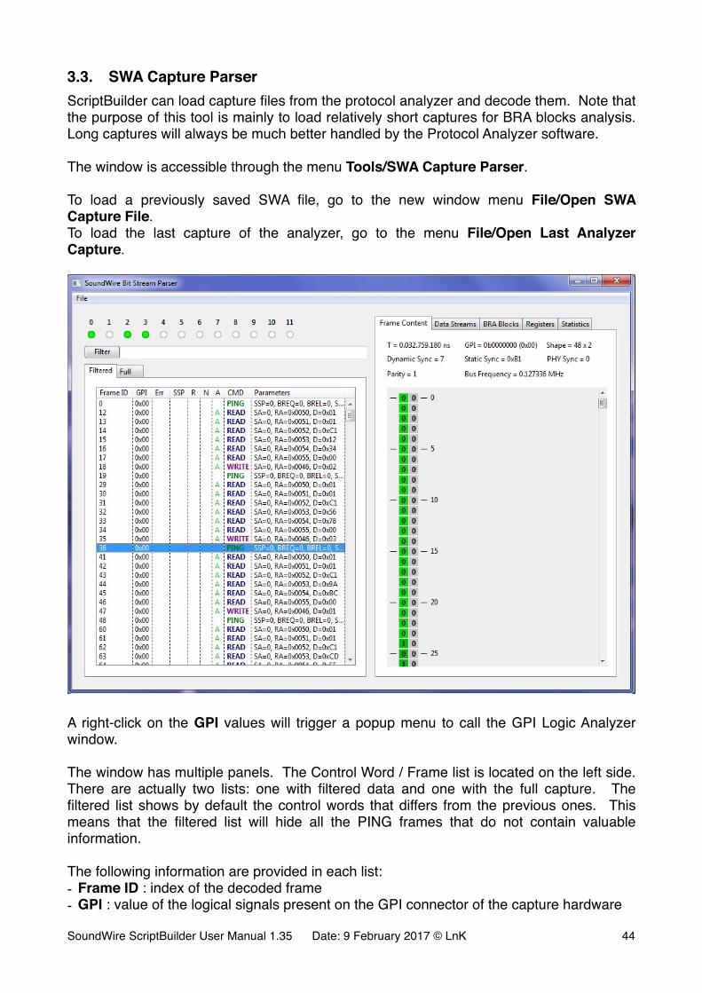
3.3. SWA Capture ParserScriptBuilder can load capture files from the protocol analyzer and decode them. Note that the purpose of this tool is mainly to load relatively short captures for BRA blocks analysis. Long captures will always be much better handled by the Protocol Analyzer software.
The window is accessible through the menu Tools/SWA Capture Parser.
To load a previously saved SWA file, go to the new window menu File/Open SWA Capture File.To load the last capture of the analyzer, go to the menu File/Open Last Analyzer Capture.
�
A right-click on the GPI values will trigger a popup menu to call the GPI Logic Analyzer window.
The window has multiple panels. The Control Word / Frame list is located on the left side. There are actually two lists: one with filtered data and one with the full capture. The filtered list shows by default the control words that differs from the previous ones. This means that the filtered list will hide all the PING frames that do not contain valuable information.
The following information are provided in each list:- Frame ID : index of the decoded frame- GPI : value of the logical signals present on the GPI connector of the capture hardware
SoundWire ScriptBuilder User Manual 1.35 Date: 9 February 2017 © LnK �44
- Err : indicates that the frame contains an error. Right-click on it to get more details- SSP : indicates that the beginning of a frame is a Stream Synchronization Point- R : indicates a PING Request (PREQ bit)- N : indicates a NAK (Negative Acknowledgment) in the frame response bits- A : indicates a ACK (Positive Acknowledgment) in the frame response bits- CMD : Control Word commands (PING, READ, WRITE)- Parameters : command arguments
It is possible to use the Filtered list to search particular events. Just type in the search field the desired request and hit enter or press the Filter button. To come back to the initial filtered list, leave the search test field empty and hit enter or press the Filter button.
For instance, to find all the READ commands of a capture, type “read” (case does not matter). If only the READ commands for slave address 1 are needed, type “read sa=1”. The search is performed on the text appearing in the list with the following exceptions:- ACK will find all the positively acknowledged commands- NAK will find all the negatively acknowledge commands- ERR will list all the errors, even the ones not appearing in the initial filtered list- SSP will list the frames which contain a Stream Synchronization Point- PREQ will list the frames containing a PREQ bit set- ENUM will list the commands involved in a slave enumeration- SHAPE will list the commands involved in a frame shape change or a bank switch- PAGE will list the commands involved in a memory page change in slaves- DP=n (n being a data port number) will list all the commands involved in the data port n
configuration
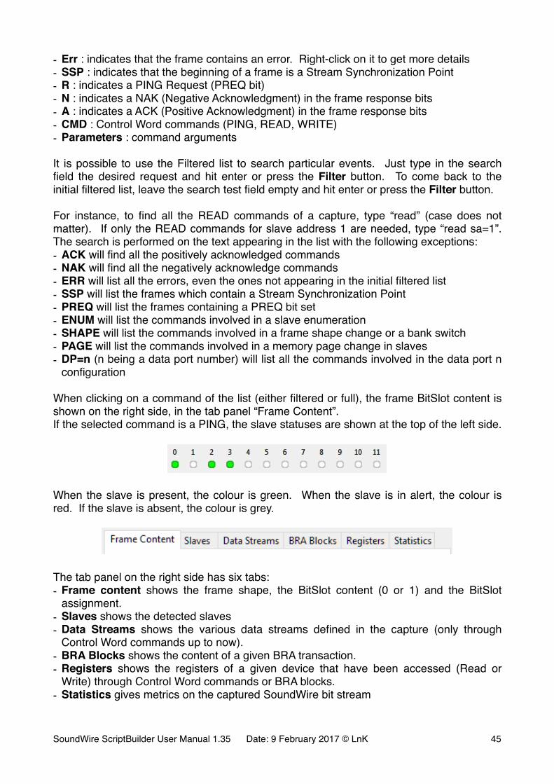
When clicking on a command of the list (either filtered or full), the frame BitSlot content is shown on the right side, in the tab panel “Frame Content”.If the selected command is a PING, the slave statuses are shown at the top of the left side.
�
When the slave is present, the colour is green. When the slave is in alert, the colour is red. If the slave is absent, the colour is grey.
�
The tab panel on the right side has six tabs:- Frame content shows the frame shape, the BitSlot content (0 or 1) and the BitSlot
assignment.- Slaves shows the detected slaves- Data Streams shows the various data streams defined in the capture (only through
Control Word commands up to now).- BRA Blocks shows the content of a given BRA transaction.- Registers shows the registers of a given device that have been accessed (Read or
Write) through Control Word commands or BRA blocks.- Statistics gives metrics on the captured SoundWire bit stream
SoundWire ScriptBuilder User Manual 1.35 Date: 9 February 2017 © LnK �45
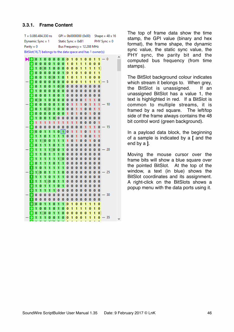
3.3.1. Frame ContentThe top of frame data show the time stamp, the GPI value (binary and hex format), the frame shape, the dynamic sync value, the static sync value, the PHY sync, the parity bit and the computed bus frequency (from time stamps).
The BitSlot background colour indicates which stream it belongs to. When grey, the BitSlot is unassigned. If an unassigned BitSlot has a value 1, the text is highlighted in red. If a BitSlot is common to multiple streams, it is framed by a red square. The left/top side of the frame always contains the 48 bit control word (green background).
In a payload data block, the beginning of a sample is indicated by a [ and the end by a ].
Moving the mouse cursor over the frame bits will show a blue square over the pointed BitSlot. At the top of the window, a text (in blue) shows the BitSlot coordinates and its assignment. A right-click on the BitSlots shows a popup menu with the data ports using it.
SoundWire ScriptBuilder User Manual 1.35 Date: 9 February 2017 © LnK �46

3.3.2. SlavesThe 48 bit unique slave ID is decoded and its various fields are displayed. If an enumeration sequence has not been captured, all the values will be equal to 0.
Groups, if any, are also shown.
SoundWire ScriptBuilder User Manual 1.35 Date: 9 February 2017 © LnK �47
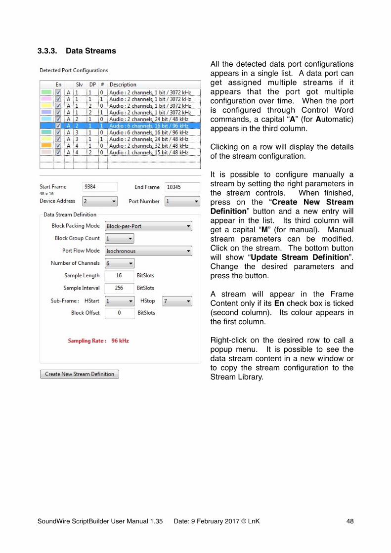
3.3.3. Data StreamsAll the detected data port configurations appears in a single list. A data port can get assigned multiple streams if it appears that the port got multiple configuration over time. When the port is configured through Control Word commands, a capital “A” (for Automatic) appears in the third column.
Clicking on a row will display the details of the stream configuration.
It is possible to configure manually a stream by setting the right parameters in the stream controls. When finished, press on the “Create New Stream Definition” button and a new entry will appear in the list. Its third column will get a capital “M” (for manual). Manual stream parameters can be modified. Click on the stream. The bottom button will show “Update Stream Definition”. Change the desired parameters and press the button.
A stream will appear in the Frame Content only if its En check box is ticked (second column). Its colour appears in the first column.
Right-click on the desired row to call a popup menu. It is possible to see the data stream content in a new window or to copy the stream configuration to the Stream Library.
SoundWire ScriptBuilder User Manual 1.35 Date: 9 February 2017 © LnK �48
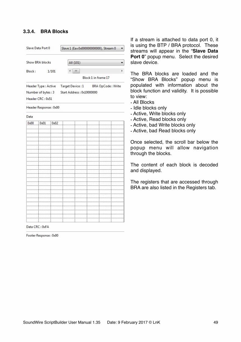
3.3.4. BRA BlocksIf a stream is attached to data port 0, it is using the BTP / BRA protocol. These streams will appear in the “Slave Data Port 0” popup menu. Select the desired slave device.
The BRA blocks are loaded and the “Show BRA Blocks” popup menu is populated with information about the block function and validity. It is possible to view:- All Blocks- Idle blocks only- Active, Write blocks only- Active, Read blocks only- Active, bad Write blocks only- Active, bad Read blocks only
Once selected, the scroll bar below the popup menu will allow navigation through the blocks.
The content of each block is decoded and displayed.
The registers that are accessed through BRA are also listed in the Registers tab.
SoundWire ScriptBuilder User Manual 1.35 Date: 9 February 2017 © LnK �49
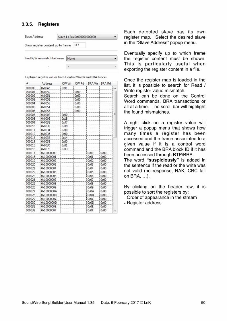
3.3.5. RegistersEach detected slave has its own register map. Select the desired slave in the “Slave Address” popup menu.
Eventually specify up to which frame the register content must be shown. This is part icularly useful when exporting the register content in a file.
Once the register map is loaded in the list, it is possible to search for Read / Write register value mismatch.Search can be done on the Control Word commands, BRA transactions or all at a time. The scroll bar will highlight the found mismatches.
A right click on a register value will trigger a popup menu that shows how many times a register has been accessed and the frame associated to a given value if it is a control word command and the BRA block ID if it has been accessed through BTP/BRA.The word “suspiciously” is added in the sentence if the read or the write was not valid (no response, NAK, CRC fail on BRA, …).
By clicking on the header row, it is possible to sort the registers by:- Order of appearance in the stream- Register address
SoundWire ScriptBuilder User Manual 1.35 Date: 9 February 2017 © LnK �50
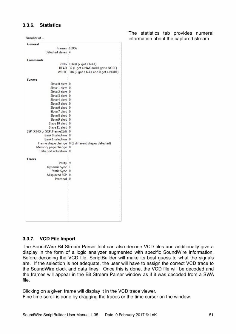
3.3.6. StatisticsThe statistics tab provides numeral information about the captured stream.
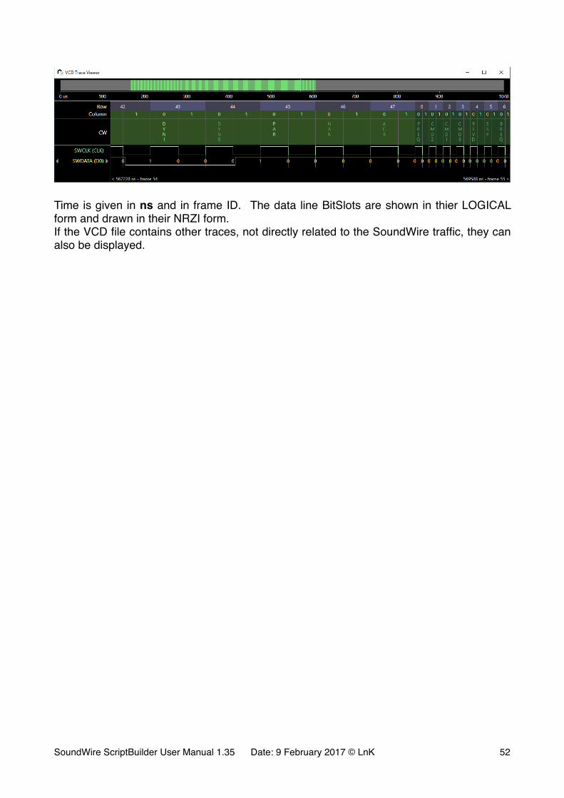
3.3.7. VCD File ImportThe SoundWire Bit Stream Parser tool can also decode VCD files and additionally give a display in the form of a logic analyzer augmented with specific SoundWire information. Before decoding the VCD file, ScriptBuilder will make its best guess to what the signals are. If the selection is not adequate, the user will have to assign the correct VCD trace to the SoundWire clock and data lines. Once this is done, the VCD file will be decoded and the frames will appear in the Bit Stream Parser window as if it was decoded from a SWA file.
Clicking on a given frame will display it in the VCD trace viewer.Fine time scroll is done by dragging the traces or the time cursor on the window.
SoundWire ScriptBuilder User Manual 1.35 Date: 9 February 2017 © LnK �51
�
Time is given in ns and in frame ID. The data line BitSlots are shown in thier LOGICAL form and drawn in their NRZI form.If the VCD file contains other traces, not directly related to the SoundWire traffic, they can also be displayed.
SoundWire ScriptBuilder User Manual 1.35 Date: 9 February 2017 © LnK �52
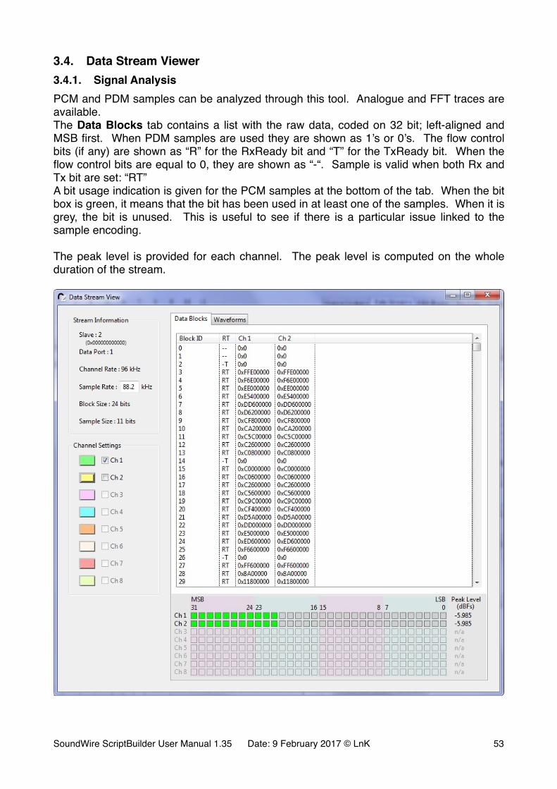
3.4. Data Stream Viewer3.4.1. Signal AnalysisPCM and PDM samples can be analyzed through this tool. Analogue and FFT traces are available.The Data Blocks tab contains a list with the raw data, coded on 32 bit; left-aligned and MSB first. When PDM samples are used they are shown as 1’s or 0’s. The flow control bits (if any) are shown as “R” for the RxReady bit and “T” for the TxReady bit. When the flow control bits are equal to 0, they are shown as “-“. Sample is valid when both Rx and Tx bit are set: “RT”A bit usage indication is given for the PCM samples at the bottom of the tab. When the bit box is green, it means that the bit has been used in at least one of the samples. When it is grey, the bit is unused. This is useful to see if there is a particular issue linked to the sample encoding.
The peak level is provided for each channel. The peak level is computed on the whole duration of the stream.
�
SoundWire ScriptBuilder User Manual 1.35 Date: 9 February 2017 © LnK �53
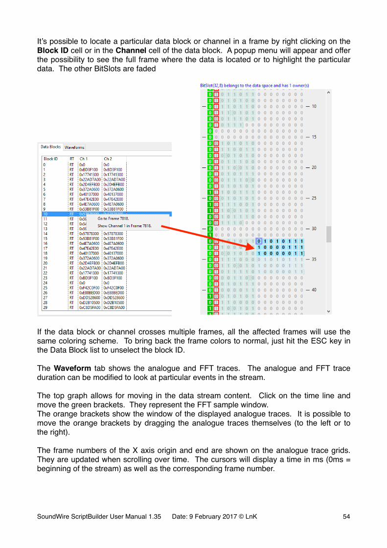
It’s possible to locate a particular data block or channel in a frame by right clicking on the Block ID cell or in the Channel cell of the data block. A popup menu will appear and offer the possibility to see the full frame where the data is located or to highlight the particular data. The other BitSlots are faded
� �
If the data block or channel crosses multiple frames, all the affected frames will use the same coloring scheme. To bring back the frame colors to normal, just hit the ESC key in the Data Block list to unselect the block ID.
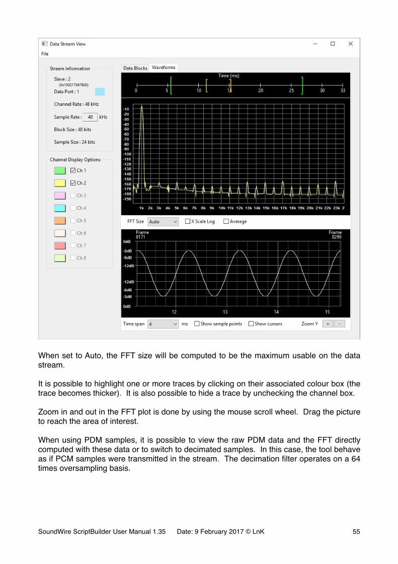
The Waveform tab shows the analogue and FFT traces. The analogue and FFT trace duration can be modified to look at particular events in the stream.
The top graph allows for moving in the data stream content. Click on the time line and move the green brackets. They represent the FFT sample window.The orange brackets show the window of the displayed analogue traces. It is possible to move the orange brackets by dragging the analogue traces themselves (to the left or to the right).
The frame numbers of the X axis origin and end are shown on the analogue trace grids. They are updated when scrolling over time. The cursors will display a time in ms (0ms = beginning of the stream) as well as the corresponding frame number.
SoundWire ScriptBuilder User Manual 1.35 Date: 9 February 2017 © LnK �54
�
When set to Auto, the FFT size will be computed to be the maximum usable on the data stream.
It is possible to highlight one or more traces by clicking on their associated colour box (the trace becomes thicker). It is also possible to hide a trace by unchecking the channel box.
Zoom in and out in the FFT plot is done by using the mouse scroll wheel. Drag the picture to reach the area of interest.
When using PDM samples, it is possible to view the raw PDM data and the FFT directly computed with these data or to switch to decimated samples. In this case, the tool behave as if PCM samples were transmitted in the stream. The decimation filter operates on a 64 times oversampling basis.
SoundWire ScriptBuilder User Manual 1.35 Date: 9 February 2017 © LnK �55
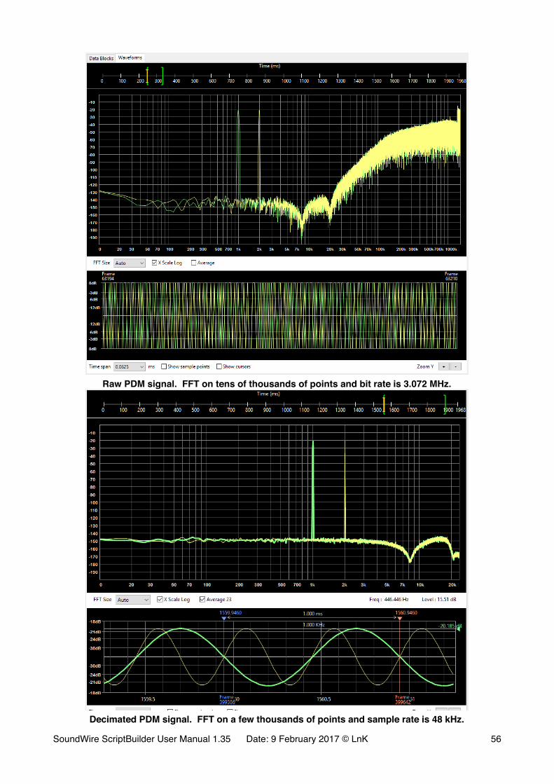
�Raw PDM signal. FFT on tens of thousands of points and bit rate is 3.072 MHz.
�Decimated PDM signal. FFT on a few thousands of points and sample rate is 48 kHz.
SoundWire ScriptBuilder User Manual 1.35 Date: 9 February 2017 © LnK �56
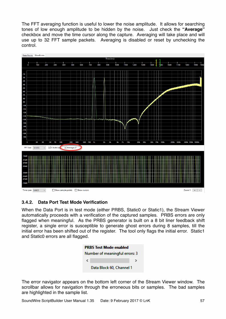
The FFT averaging function is useful to lower the noise amplitude. It allows for searching tones of low enough amplitude to be hidden by the noise. Just check the “Average” checkbox and move the time cursor along the capture. Averaging will take place and will use up to 32 FFT sample packets. Averaging is disabled or reset by unchecking the control.
�
3.4.2. Data Port Test Mode VerificationWhen the Data Port is in test mode (either PRBS, Static0 or Static1), the Stream Viewer automatically proceeds with a verification of the captured samples. PRBS errors are only flagged when meaningful. As the PRBS generator is built on a 8 bit liner feedback shift register, a single error is susceptible to generate ghost errors during 8 samples, till the initial error has been shifted out of the register. The tool only flags the initial error. Static1 and Static0 errors are all flagged.
�
The error navigator appears on the bottom left corner of the Stream Viewer window. The scrollbar allows for navigation through the erroneous bits or samples. The bad samples are highlighted in the sample list.SoundWire ScriptBuilder User Manual 1.35 Date: 9 February 2017 © LnK �57
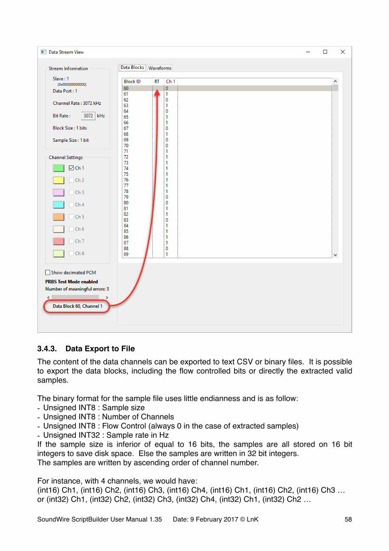
�
3.4.3. Data Export to FileThe content of the data channels can be exported to text CSV or binary files. It is possible to export the data blocks, including the flow controlled bits or directly the extracted valid samples.
The binary format for the sample file uses little endianness and is as follow:- Unsigned INT8 : Sample size- Unsigned INT8 : Number of Channels- Unsigned INT8 : Flow Control (always 0 in the case of extracted samples)- Unsigned INT32 : Sample rate in HzIf the sample size is inferior of equal to 16 bits, the samples are all stored on 16 bit integers to save disk space. Else the samples are written in 32 bit integers.The samples are written by ascending order of channel number.
For instance, with 4 channels, we would have:(int16) Ch1, (int16) Ch2, (int16) Ch3, (int16) Ch4, (int16) Ch1, (int16) Ch2, (int16) Ch3 …or (int32) Ch1, (int32) Ch2, (int32) Ch3, (int32) Ch4, (int32) Ch1, (int32) Ch2 …
SoundWire ScriptBuilder User Manual 1.35 Date: 9 February 2017 © LnK �58
When saving PDM data, the 1 bit samples are concatenated in an 8 bit integer by ascending order of channel number. If a data port has 3 channels enabled, the bit arrangement in the file byte will be according to the next table.
The binary file format for the data blocks is almost identical.The flow control bits are written in a 8 bit integer before the sample values.For instance, with 3 channels, we would have:(int8) Flow, (int16) Ch1, (int16) Ch2, (int16) Ch3, (int16) Ch1, (int16) Ch2, (int16) Ch3 …or (int8) Flow, (int32) Ch1, (int32) Ch2, (int32) Ch3, (int32) Ch1, (int32) Ch2 …
Note that for PDM, the flow control does not apply and the content of the two binary exports will be identical.
b7 b6 b5 b4 b3 b2 b1 b0
Byte 0 ch1 ch2 ch3 ch1 ch2 ch3 ch1 ch2
Byte 1 ch3 ch1 ch2 ch3 ch1 ch2 ch3 ch1
SoundWire ScriptBuilder User Manual 1.35 Date: 9 February 2017 © LnK �59
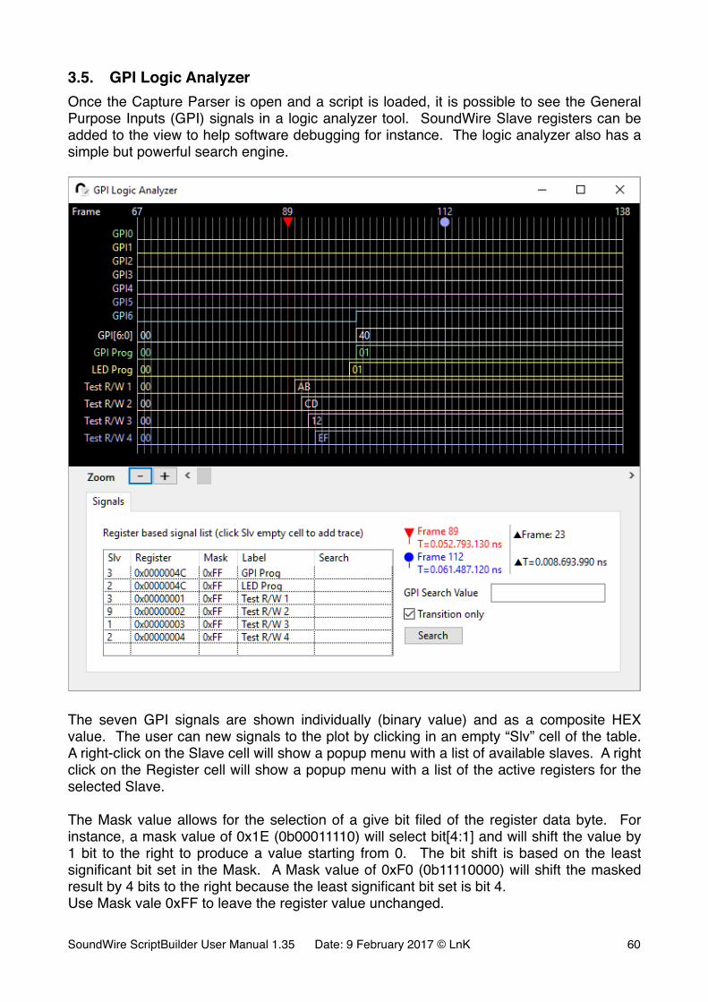
3.5. GPI Logic AnalyzerOnce the Capture Parser is open and a script is loaded, it is possible to see the General Purpose Inputs (GPI) signals in a logic analyzer tool. SoundWire Slave registers can be added to the view to help software debugging for instance. The logic analyzer also has a simple but powerful search engine.
�
The seven GPI signals are shown individually (binary value) and as a composite HEX value. The user can new signals to the plot by clicking in an empty “Slv” cell of the table. A right-click on the Slave cell will show a popup menu with a list of available slaves. A right click on the Register cell will show a popup menu with a list of the active registers for the selected Slave.
The Mask value allows for the selection of a give bit filed of the register data byte. For instance, a mask value of 0x1E (0b00011110) will select bit[4:1] and will shift the value by 1 bit to the right to produce a value starting from 0. The bit shift is based on the least significant bit set in the Mask. A Mask value of 0xF0 (0b11110000) will shift the masked result by 4 bits to the right because the least significant bit set is bit 4.Use Mask vale 0xFF to leave the register value unchanged.
SoundWire ScriptBuilder User Manual 1.35 Date: 9 February 2017 © LnK �60

The Label is the name of the signal shown on the plot.
The Search value is optional and can be left blank. A empty search value will exclude the signal from the search procedure.The Search value can accept decimal entries, hexadecimal entries (in the form of 0x12) or binary entries (in the form of 0b11001111). When using the binary format, don’t care bits can be specified by using the X symbol. For instance, the Search value 0b11XX0011 will mask the signal value with 0b11001111 and run the search check on the resulting value.
The search engine proceed with an inclusive search on all the values. All the conditions must be true to flag a frame as a search hit.
It’s possible to request the search engine to find all the matches or only the ones that are becoming true after a transition from false. This reduce the number of search result items and flags the dynamic changes of the GPI and bus registers.
�
Once the search is over, the user can navigate through the found frames by clicking on the Prev. or Next buttons. The plot shows the frame of interest on its left side.
SoundWire ScriptBuilder User Manual 1.35 Date: 9 February 2017 © LnK �61
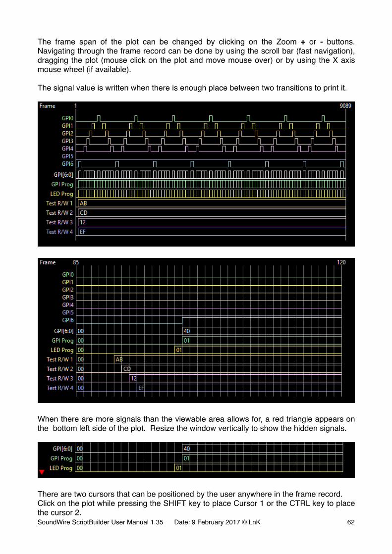
The frame span of the plot can be changed by clicking on the Zoom + or - buttons. Navigating through the frame record can be done by using the scroll bar (fast navigation), dragging the plot (mouse click on the plot and move mouse over) or by using the X axis mouse wheel (if available).
The signal value is written when there is enough place between two transitions to print it.
�
�
When there are more signals than the viewable area allows for, a red triangle appears on the bottom left side of the plot. Resize the window vertically to show the hidden signals.
�
There are two cursors that can be positioned by the user anywhere in the frame record.Click on the plot while pressing the SHIFT key to place Cursor 1 or the CTRL key to place the cursor 2.SoundWire ScriptBuilder User Manual 1.35 Date: 9 February 2017 © LnK �62

The cursor can be recalled by clicking on the cursor symbols in the panel. The cursor information include the differential in frames and time.
�
SoundWire ScriptBuilder User Manual 1.35 Date: 9 February 2017 © LnK �63
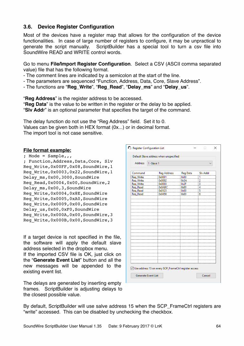
3.6. Device Register ConfigurationMost of the devices have a register map that allows for the configuration of the device functionalities. In case of large number of registers to configure, it may be unpractical to generate the script manually. ScriptBuilder has a special tool to turn a csv file into SoundWire READ and WRITE control words.
Go to menu File/Import Register Configuration. Select a CSV (ASCII comma separated value) file that has the following format.- The comment lines are indicated by a semicolon at the start of the line.- The parameters are sequenced “Function, Address, Data, Core, Slave Address”.- The functions are “Reg_Write”, “Reg_Read”, “Delay_ms” and “Delay_us”.
“Reg Address” is the register address to be accessed.“Reg Data” is the value to be written in the register or the delay to be applied.“Slv Addr” is an optional parameter that specifies the target of the command.
The delay function do not use the “Reg Address” field. Set it to 0.Values can be given both in HEX format (0x...) or in decimal format.The import tool is not case sensitive.
File format example:; Mode = Sample,,,; Function,Address,Data,Core, SlvReg_Write,0x00FF,0x08,SoundWire,1Reg_Write,0x0003,0x22,SoundWire,1Delay_ms,0x00,3000,SoundWireReg_Read,0x0004,0x00,SoundWire,2Delay_ms,0x00,3,SoundWireReg_Write,0x0004,0x8E,SoundWireReg_Write,0x0005,0xA0,SoundWireReg_Write,0x0009,0x00,SoundWireDelay_us,0x00,0xF0,SoundWireReg_Write,0x000A,0x00,SoundWire,3Reg_Write,0x000B,0x00,SoundWire,3
If a target device is not specified in the file, the software will apply the default slave address selected in the dropbox menu.If the imported CSV file is OK, just click on the “Generate Event List” button and all the new messages will be appended to the existing event list.
The delays are generated by inserting empty frames. ScriptBuilder is adjusting delays to the closest possible value.
By default, ScriptBuilder will use salve address 15 when the SCP_FrameCtrl registers are “write” accessed. This can be disabled by unchecking the checkbox.
SoundWire ScriptBuilder User Manual 1.35 Date: 9 February 2017 © LnK �64
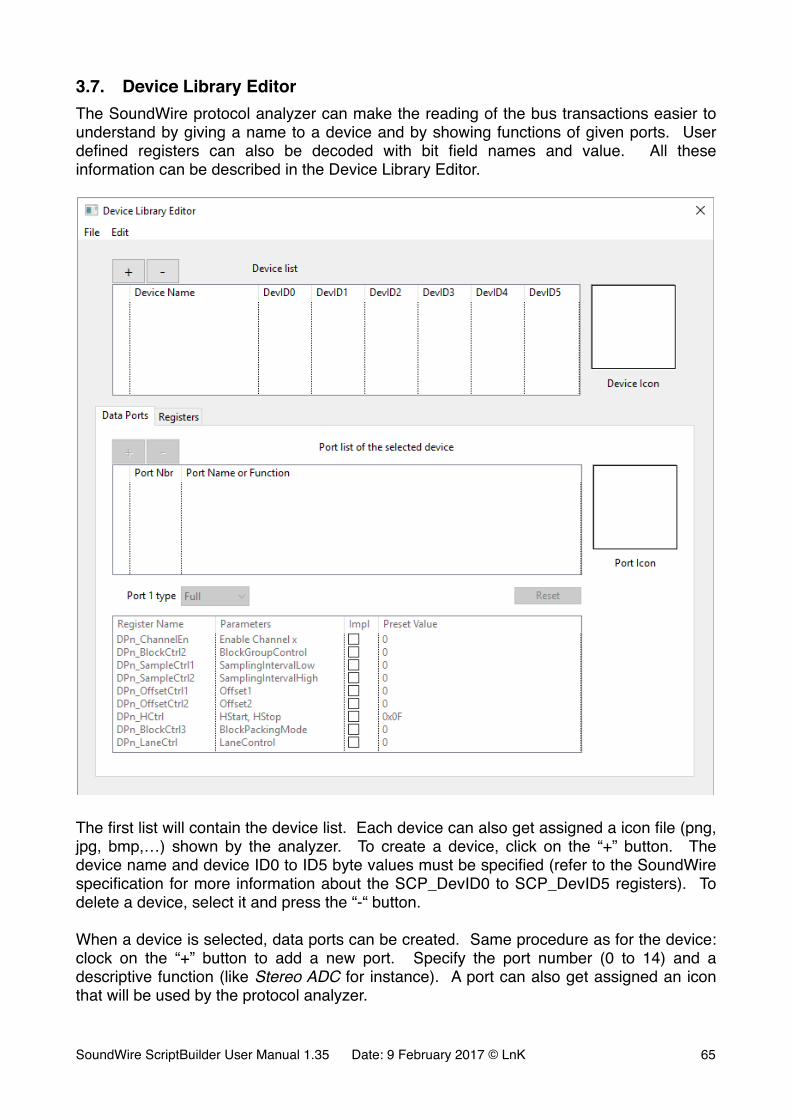
3.7. Device Library EditorThe SoundWire protocol analyzer can make the reading of the bus transactions easier to understand by giving a name to a device and by showing functions of given ports. User defined registers can also be decoded with bit field names and value. All these information can be described in the Device Library Editor.
�
The first list will contain the device list. Each device can also get assigned a icon file (png, jpg, bmp,…) shown by the analyzer. To create a device, click on the “+” button. The device name and device ID0 to ID5 byte values must be specified (refer to the SoundWire specification for more information about the SCP_DevID0 to SCP_DevID5 registers). To delete a device, select it and press the “-“ button.
When a device is selected, data ports can be created. Same procedure as for the device: clock on the “+” button to add a new port. Specify the port number (0 to 14) and a descriptive function (like Stereo ADC for instance). A port can also get assigned an icon that will be used by the protocol analyzer.
SoundWire ScriptBuilder User Manual 1.35 Date: 9 February 2017 © LnK �65
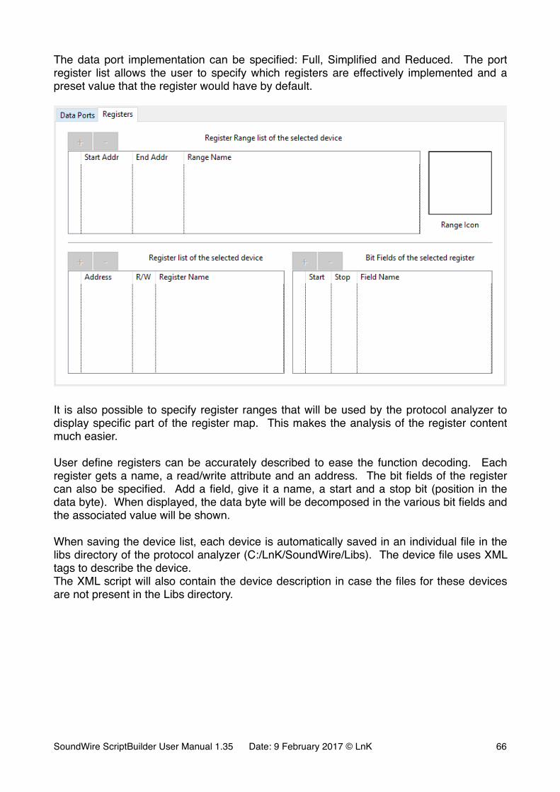
The data port implementation can be specified: Full, Simplified and Reduced. The port register list allows the user to specify which registers are effectively implemented and a preset value that the register would have by default.
�
It is also possible to specify register ranges that will be used by the protocol analyzer to display specific part of the register map. This makes the analysis of the register content much easier.
User define registers can be accurately described to ease the function decoding. Each register gets a name, a read/write attribute and an address. The bit fields of the register can also be specified. Add a field, give it a name, a start and a stop bit (position in the data byte). When displayed, the data byte will be decomposed in the various bit fields and the associated value will be shown.
When saving the device list, each device is automatically saved in an individual file in the libs directory of the protocol analyzer (C:/LnK/SoundWire/Libs). The device file uses XML tags to describe the device.The XML script will also contain the device description in case the files for these devices are not present in the Libs directory.
SoundWire ScriptBuilder User Manual 1.35 Date: 9 February 2017 © LnK �66
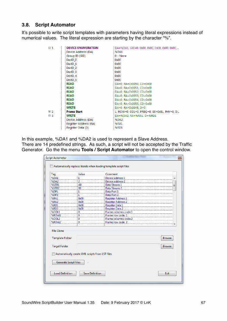
3.8. Script AutomatorIt’s possible to write script templates with parameters having literal expressions instead of numerical values. The literal expression are starting by the character “%”.
�
In this example, %DA1 and %DA2 is used to represent a Slave Address.There are 14 predefined strings. As such, a script will not be accepted by the Traffic Generator. Go the the menu Tools / Script Automator to open the control window.
�
SoundWire ScriptBuilder User Manual 1.35 Date: 9 February 2017 © LnK �67

The literal string can get assigned any given value. The user can create up to 36 new strings on top of the existing ones (colored in dark blue).When the check box is ticked, ScriptBuilder will automatically replace the strings by the define values when opening the script.
It is also possible to use the “File Clone” function and create Component specific scripts out of a template script folder.
�
Once the template folder and the target folder are identified (by using the browse buttons), click on the “Generate Script Files” button and wait for the file copy to be over. The target directory will contain the same files than the template directory, but with the string replaced by the values given in the table.
If the check box “Automatically create XML scripts from LST files” is ticked, Automator will load the modified LST files and convert them to XML. It will also generate a XMP file to be used by the SoundWire Protocol Analyzer application to build banks of script presets. This allows for a very simple navigation through scripts. If the script names are in the form of abcXY.xml (when abc are text characters and XY are numbers), Automator will group them in specific banks.
Note that the file clone tool will use all the “SoundWire” files present in the template directory: .lst (native ScriptBuilder format) and .xml (Traffic Generator input file).
SoundWire ScriptBuilder User Manual 1.35 Date: 9 February 2017 © LnK �68
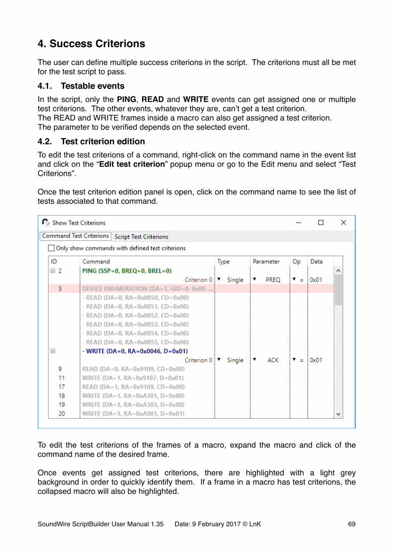
4. Success CriterionsThe user can define multiple success criterions in the script. The criterions must all be met for the test script to pass.
4.1. Testable eventsIn the script, only the PING, READ and WRITE events can get assigned one or multiple test criterions. The other events, whatever they are, can’t get a test criterion.The READ and WRITE frames inside a macro can also get assigned a test criterion.The parameter to be verified depends on the selected event.
4.2. Test criterion editionTo edit the test criterions of a command, right-click on the command name in the event list and click on the “Edit test criterion” popup menu or go to the Edit menu and select “Test Criterions”.
Once the test criterion edition panel is open, click on the command name to see the list of tests associated to that command.
�
To edit the test criterions of the frames of a macro, expand the macro and click of the command name of the desired frame.
Once events get assigned test criterions, there are highlighted with a light grey background in order to quickly identify them. If a frame in a macro has test criterions, the collapsed macro will also be highlighted.
SoundWire ScriptBuilder User Manual 1.35 Date: 9 February 2017 © LnK �69
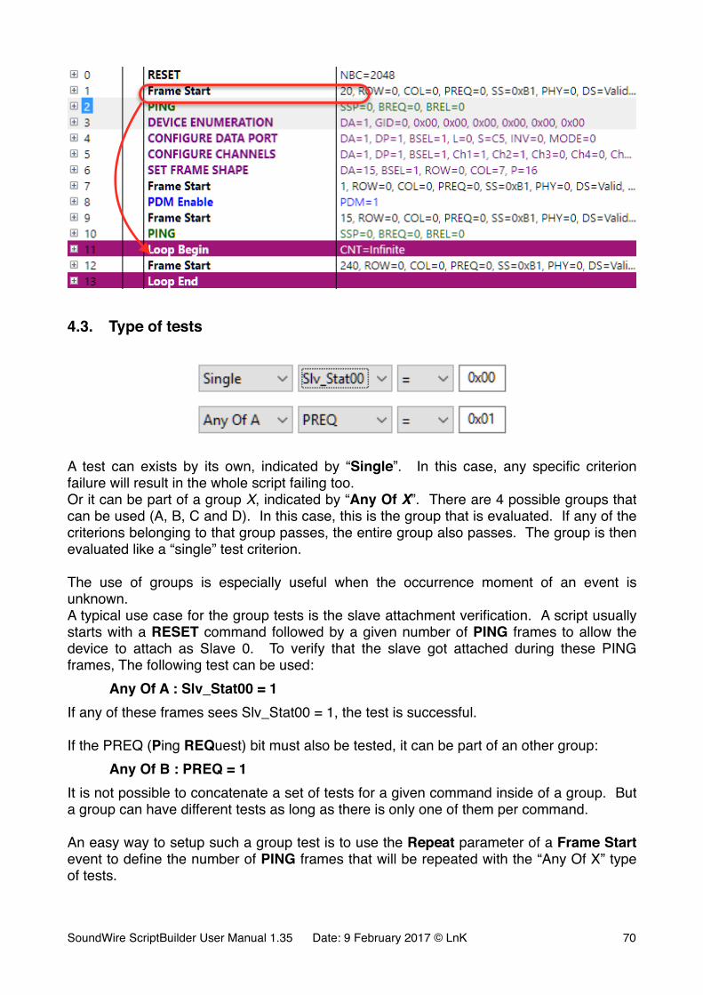
�
4.3. Type of tests
�
�
A test can exists by its own, indicated by “Single”. In this case, any specific criterion failure will result in the whole script failing too.Or it can be part of a group X, indicated by “Any Of X”. There are 4 possible groups that can be used (A, B, C and D). In this case, this is the group that is evaluated. If any of the criterions belonging to that group passes, the entire group also passes. The group is then evaluated like a “single” test criterion.
The use of groups is especially useful when the occurrence moment of an event is unknown.A typical use case for the group tests is the slave attachment verification. A script usually starts with a RESET command followed by a given number of PING frames to allow the device to attach as Slave 0. To verify that the slave got attached during these PING frames, The following test can be used:
Any Of A : Slv_Stat00 = 1If any of these frames sees Slv_Stat00 = 1, the test is successful.
If the PREQ (Ping REQuest) bit must also be tested, it can be part of an other group:Any Of B : PREQ = 1
It is not possible to concatenate a set of tests for a given command inside of a group. But a group can have different tests as long as there is only one of them per command.
An easy way to setup such a group test is to use the Repeat parameter of a Frame Start event to define the number of PING frames that will be repeated with the “Any Of X” type of tests.
SoundWire ScriptBuilder User Manual 1.35 Date: 9 February 2017 © LnK �70
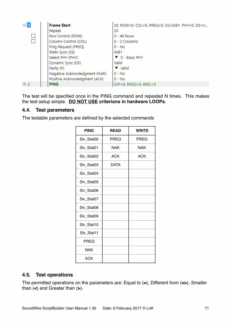
�
The test will be specified once in the PING command and repeated N times. This makes the test setup simple. DO NOT USE criterions in hardware LOOPs.
4.4. Test parametersThe testable parameters are defined by the selected commands
4.5. Test operationsThe permitted operations on the parameters are: Equal to (=), Different from (<>), Smaller than (<) and Greater than (>).
PING READ WRITE
Slv_Stat00 PREQ PREQ
Slv_Stat01 NAK NAK
Slv_Stat02 ACK ACK
Slv_Stat03 DATA
Slv_Stat04
Slv_Stat05
Slv_Stat06
Slv_Stat07
Slv_Stat08
Slv_Stat09
Slv_Stat10
Slv_Stat11
PREQ
NAK
ACK
SoundWire ScriptBuilder User Manual 1.35 Date: 9 February 2017 © LnK �71
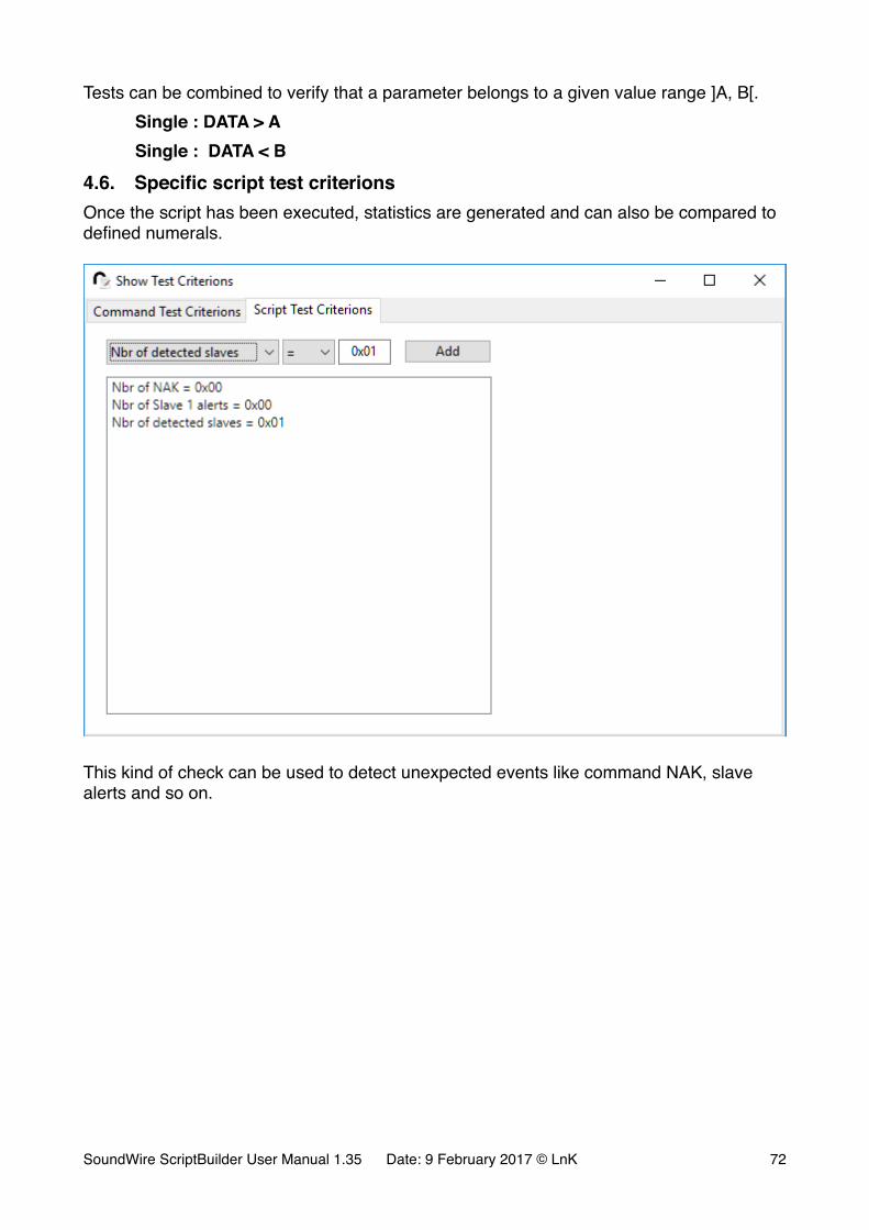
Tests can be combined to verify that a parameter belongs to a given value range ]A, B[.Single : DATA > ASingle : DATA < B
4.6. Specific script test criterionsOnce the script has been executed, statistics are generated and can also be compared to defined numerals.
�
This kind of check can be used to detect unexpected events like command NAK, slave alerts and so on.
SoundWire ScriptBuilder User Manual 1.35 Date: 9 February 2017 © LnK �72
5. Remote Control and DLLScriptBuilder comes with a DLL for remote control. The DLL is suitable for integration in C++, Visual Basic and many other Windows programming languages.The provided files are:- LnKSoundWireScriptBuilder_IF.lib- LnKSoundWireScriptBuilder_IF.dll- LnKSoundWireScriptBuilder_IF.h
Use the .lib and .dll file in your own application.The header file (.h) is meant to be used in a C++ application and is giving the necessary function prototypes. Read carefully the header file to have a detailed description of the function parameters and the returned values.
The DLL provides all the necessary calls to build automation around ScriptBuilder. the basic functions are file open, file save, file append, register file import, XML generation and export and event list clear all.
SoundWire ScriptBuilder User Manual 1.35 Date: 9 February 2017 © LnK �73


![[MS-SHLLINK]: Shell Link (.LNK) Binary File Format · PDF fileShell Link (.LNK) Binary File Format ... Tuesday, June 1, 2010 [MS-SHLLINK]: Shell Link (.LNK) Binary File Format](https://img.dokumen.tips/doc/110x75/5a93a2e77f8b9aba4a8ba978/ms-shllink-shell-link-lnk-binary-file-format-link-lnk-binary-file-format.jpg)


![Profi Hub F1 - Procentec€¦ · profi hub f1 z µv v dµo rd} &] k ^Ç u dz w }(] ... lmt lnk/act fail lmt lnk/act sta rx rx tx rx tx pwr fail fail lmt lnk/act fail lmt lnk/act sta](https://img.dokumen.tips/doc/110x75/5aec886c7f8b9a66258eb30a/profi-hub-f1-procentec-profi-hub-f1-z-v-v-do-rd-k-u-dz-w-lmt-lnkact.jpg)