Embed Size (px)
Citation preview

JLMN-Journal of Laser Micro/Nanoengineering Vol. 7, No. 3, 2012
326
Laser Assisted Frit Sealing for High Thermal Expansion Glasses.
Stephan Logunov, Sasha Marjanovic, Jitendra Balakrishnan Science and Technology, Corning Incorporated, Corning, NY 14831
Abstract Analysis of laser assisted frit sealing processes for high CTE > 5x10⁻⁶/°C (coefficient of thermal expansion) glasses
was done. The method is based on the thermal fusion of two glasses with a low melting point glass frit. This method is used when thermal sensitive materials such as OLED (organic light emissive device) are present in the glass package. The frit is selected to be highly absorbent at the sealing laser wavelength, while the glasses are transparent at the sealing wavelength. It was found that laser sealing of a high CTE glass with sealing conditions optimized for a low CTE (< 5x10⁻⁶/°C) glass, such as glass suitable for display devices, produces very poor results. The issue with sealing glasses with high CTE is high transient stress formed during heating and cooling the glass to the sealing temperatures. The sealing yield of high CTE glasses could be significantly improved by increasing “residential heating time” by reducing sealing speed or increasing laser spot size. This results in lower cooling rate of the glass and helps to reduce the residual stress. This was confirmed by stress analysis showing a reduction of the stress for soda lime glass with increasing residential heating time.
Keywords: laser applications, glass, laser material modifications
Introduction
Encapsulation of moisture and oxygen sensitive devices is an important part of manufacturing organic light emitting diode (OLED) displays, OLED lighting devices, and other glass hermetic thin-film devices. The organic films provide self-illumination for OLEDs. However, organic films pose a problem: displayed image quality and intensity degrade when exposed to oxygen and moisture, which leads to premature failure of the device. Therefore, the device must be hermetically sealed. These materials are highly thermal sensitive and degrade at temperature over 110 °C even exposed for a short period of time. There have been many schemes developed to provide hermetic encapsulation of organic thin-film devices. The most common approach uses UV-curable epoxy [1,2]. Since the epoxy still allows the penetration of moisture and oxygen, a desiccant must be positioned inside the device to slow the reactions between moisture, oxygen and the organic thin films. Another technique utilizes a thin film encapsulation. In this method, thin films comprising organic and inorganic layers, such as polyacrylate and Al2O3 respectively, are deposited on top of the OLED device [3]. However, it is difficult to provide acceptable encapsulation by thin films alone due to film defects such as pin holes and cracks. Nevertheless, for any of the above mentioned encapsulation technologies for OLED devices, the ingress of moisture and oxygen should be less than 10-5 g/m2/day and 10-6 cm3/m2/day penetration, respectively, otherwise the OLED device will suffer image degradation at a later time.
Laser sealing is technique, which is proven to provide hermetic packaging. The glass with OLEDs and printed electronics is sealed to cover glass. Laser sealing technique was used to seal clear to absorbing glass [4] or using ultrashort laser pulsed radiation to join two transparent glasses utilizing non-linear absorption of the material [5-7]. However, in OLED packaging case, there always non-transparent materials such as metal electrodes or other electronics in the seal area. This fact makes use of the such laser sealing techniques difficult since glass cover plate needs to be sealed to another glass plate with light absorbing electronics printed, which may get damaged. To overcome these problems for for OLED packaging, a new
sealing technology was developed by using highly absorbing glass frits. Low temperature glass frits [8-13] are dispensed on a glass substrate with a precision dispensing device. After the frit is sintered, the substrate with frit is placed on top of an OLED substrate and sealed by a laser. The frit layer transmittance is very low, so no laser radiation reaches bottom plate with OLEDs and printed electronics. When the frit is exposed to a laser beam at a wavelength tailored for the frit absorption, the frit highly absorbs the laser light and converts the light into heat. The top glass, which laser radiation enters to the package, is transparent at the laser wavelength. The temperature of the frit increases above its softening point and is sealed to the OLED substrate. The laser spot is moved with high speed, minimizing the heat affected zone and leaving all electronics and OLED materials intact during the sealing process. During this process temperature rise is less than 80 °C at distance from the frit line > 100 microns, the OLED materials and other heat sensitive elements are typically ~ 300-400 microns away from edge of the sealing line It was demonstrated that by using inexpensive laser sources it is possible to encapsulate different OLED displays with a variety of electrode configurations with superior hermeticity [9-10].
It has been shown that laser assisted frit sealing of OLEDs using display glass with low CTE (3-5x10⁻⁶/oC) is feasible at speeds up to 30-50 mm/s with spot size slightly larger than width of the frit line, typically ~ 0.7 mm. This laser sealing conditions will call SSP (standard sealing parameters). The SSP are laser power of 30-40 W at CW (continuous wave) mode, spot size 1.3-1.8 mm (for frit sealing lines 0.7 mm wide), and sealing speed 30-50 mm/s, some additional examples can be found in [14]. High sealing speed is an important requirement to enable a cost efficient manufacturing process. In non-display applications, such as solid state lighting, where lower cost glasses can be employed, display-quality glass may be cost-prohibitive. Instead, manufacturers prefer to use less expensive glass, such as soda lime glass. For these type glasses CTE is much higher ~ 8-9x10⁻⁶/oC. This study presents results for laser assisted sealing of high CTE glasses including soda lime glass. We investigate glass
JLMN-Journal of Laser Micro/Nanoengineering Vol. 7, No. 3, 2012
327
sealing using visual inspection and hermetic tests in an 85°C/85% relative humidity (RH) environmental chamber. We also studied stresses incurred in the sealed glass during the sealing process. We found that the limiting factors for sealing high CTE glasses are transient and residual stresses associated with the laser sealing process.
We also show that sealing of soda lime glass under SSP typical for display glass (i.e. low CTE) generates significant cracking and delamination of the frit from the glass during the sealing process. We further show that stress can be reduced by changing the heating profile generated by the laser on the frit. The importance of the heating profile is critical for sealing high CTE glasses. We also show that changing the heating profile by modifying the beam spot size to a larger diameter, and adjusting the sealing speed, can reduce stress in the substrates to the point where frit sealing of soda lime glass becomes feasible. Finally, we discuss experiments with other glasses, showing the importance of such glass parameters as CTE and annealing point, and appropriate laser heating profiles.
Experimental section of the paper contains description of measurement techniques used for seal quality analysis and stress measurements. It shows analysis of different sealing process parameters impact on seal such as laser spot size, frit composition, sealing speed, glass physical properties, and glass thickness. The numerical section describes theoretical model and compares its predictions with key experimental results. The paper is concluded with discussion and conclusion session. Experimental results Evaluation of the seal quality Sealing was performed with a from Spectra Physics Integra 810 nm laser diode with an optical fiber delivery. The laser power was up to 30W at CW mode. Also Laser Line 400 W CW laser with optical fiber delivery was employed at wavelength 940 nm. The laser spot on the frit was formed by an imaging lens, forming a spot with a diameter of approximately 1 mm, which could be increased by defocusing the imaging lens. The sample was moved using an XY motion stage. Seal quality was evaluated by visual inspection using an optical microscope with bright and dark field illumination. Using this process any defects in the seal, such as possible cracking or delamination in the frit or cracking in the glass, could be observed. Typical seals capable of surviving a hermeticity test (1000 hours in 85°C/ 85% RH) are shown in Figures 1 and 2.
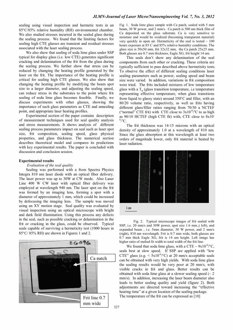
Fig. 1. Soda lime glass sample with Ca patch, sealed with 5 mm beam, 30 W power, and 2 mm/s. Ca patch is 500 nm thick film of Ca deposited on the glass substrate. Ca is very sensitive to moisture and would be oxidized (becoming transparent material) very quickly in open air. Hermeticity of the seal is tested ~ 100 hours exposure at 85 C and 85% relative humidity conditions. The glass size is 50x50 mm, frit 32x32 mm, the Ca patch 25x25 mm. Both glasses are 0.7 mm thickness, Eagle XG, frit height 14 um. This seals don’t show any delamination of the seal components from each other or cracking. These criteria are typically sufficient to pass described above hermetisity tests. To observe the effect of different sealing conditions laser sealing parameters such as power, sealing speed and beam size were varied. In addition, variations in frit composition were tried. The frits included mixtures of low temperature glass with a Tg (glass transition temperature, i.e temperature representing effective temperature, when glass transitions from liquid to glassy state) around 350°C and filler, with an 80/20 volume ratio, respectively, as well as frits having different glass/filler ratios ranging from 70/30 a NCTEF (“normal” CTE frit) with CTE close to 3x10⁻⁶/oC to as high as 90/10 HCTEF (high CTE fit) with, CTE close to 8x10-
6/oC. The frit thickness was 14-15 microns with an optical density of approximately 1.0 at a wavelength of 810 nm. Since the glass absorption at this wavelength at least two orders of magnitude lower, only frit material is heated by laser radiation.
Fig. 2. Typical microscope images of frit sealed with
SSP, i.e. 20 mm/s and 30W power, spot size 1.6 mm.,( left), and expanded beam , i.e. 5mm diameter, 30 W power, and 2 mm/s (right), 810 nm wavelength. Frit is 0.7 mm wide, both glasses are 0.7 mm thick Eagle XG, frit is 14 um height. Left image has higher ratio of melted fit width to total width of the frit line. We found that soda lime glass, with a CTE ~ 9x10⁻⁶/°C, seals best at slow speed. If SSP are applied with “low CTE” glass (e.g. < 5x10⁻⁶/°C) at 20 mm/s acceptable seals can be obtained with very high yields. With soda lime glass the sealing results would be very poor at 20 mm/s, with visible cracks in frit and glass. Better results can be obtained with soda lime glass at a slower sealing speed (~ 2 mm/s). In addition, increasing the laser beam diameter also leads to better sealing quality and yield (figure 2). Both adjustments are directed toward increasing the “effective heating time” at a given location of the sealing package. The temperature of the frit can be expressed as [10] Frit line 0.7
mm wide
Ca patch

JLMN-Journal of Laser Micro/Nanoengineering Vol. 7, No. 3, 2012
328
T= K P/a2 √(vD)εL (1),
Where T is frit sealing temperature, K is scaling coefficient, P is laser power, a is diameter of the beam, v is translation speed, D is heat diffusivity, ε is absorption of the laser radiation by frit material, L is frit height. Since the sealing temperature needs to be about the same for all sealing conditions, equation (1) allows to obtain how laser power needs to be adjusted, when translation speed and beam diameter changes. Experimental results for SSP are very close from one calculated using equation (1) as shown in [14, 15]. For given laser power spot size decrease leads to lower power required to reach the same sealing temperature. All variable parameters shown in equation (1): laser power, spot size, and sealing speed need to be adjusted together to obtain optimal sealing conditions. The target temperature for frit sealing is 500-600 °C [16]. One of the parameters affecting the residual stress in the glass and the frit is a cooling rate, i.e. how fast the temperature drops from peak temperature to ambient. In order to reduce the cooling rate, the laser moving rate needs to be reduced [6]. Since the beam profile from the laser sources we used is “Gaussian” shape or close to that, increase of the heating time leads to a lower “cooling rate” (figure 3).
0.1 0.2 0.3 0.4 0.5 0.6
300
400
500
600
Frit t
empe
ratu
re, C
Time, seconds
Cooling 2 mm/s 20 mm/s
Figure 3. Effect of the speed on cooling rate of the frit and glass. The solid line is cooling after turning off heat source at stationary conditions (exposure time 1s). The dot and dash lines are expected cooling profiles as products of the heating by Gaussian laser beam of the same diameter ~ 1.8 mm at different beam translation speeds of 2 and 20 mm/s. At 20 mm/s speed heating profile will be dominated by cooling rate similar to one at stationary conditions, at 2 mm/s cooling rate is significantly lower. The power for 20 mm/s speed condition is 33 W, and for 2 mm/s speed condition is 10 W.
Therefore, one of the measurable parameters may be “effective heating time”. Indeed, we can define “effective heating time”, τ(eff), as a/v, where a is the laser beam diameter and v is the linear translation velocity of the beam along the seal. Increasing a and decreasing v leads to an increase of τ(eff). For “low CTE” glass with a CTE of <5x10⁻⁶/°C the sealing can be done at speeds above 50 mm/s utilizing a laser spot size of 1.8 mm, this is defined earlier as SSP. The effective heating time for glass having a CTE in this low range can be below 36 ms. For higher CTE glasses, as we will show later, the effective heating time needs to be at least an order of magnitude higher.
Stress evaluation on-line and after sealing process To obtain stress in the laser-sealed parts, we measured in-situ birefringence in the sealed glass. Our measurement is similar to Tardy [17], but we monitor the birefringence using a fast video camera, enabling us to obtain transient stress, stress relaxation process, and residual stress in the sealed parts. A schematic of the measurement setup is shown in Figure 4. Narrowband light emission from a colored LED transmitted through a combination of bandpass filters is collimated and enters a linear polarizer with an extinction ratio better than 10,000. The light then passes through a circular polarizer and enters the sample. A second circular polarizer and another crossed linear polarizer are placed after the sample. Amount of transmitted light depends on birefringence of the sample.
Fig. 4. Optical setup for on-line birefringence monitoring during sealing process. LP polarizes light at the plane oriented 45 relative to the sample orientation, CP is circular polarizer created circular polarized light at the sample entrance, CP after sample removes circular polarization, and LP after sample serves as analyzer crossed with first LP. CF is color filter blocking scattered laser radiation. The cutoff filter in front of the camera ensures none of the scattered laser radiation at 810 nm, or heat emission during the sealing process, reaches the camera detector. The camera is connected to a frame grabber and using Streampix software, where a maximum acquisition rate of 60 frames per second is possible. The gray scale of the camera image is proportional to the birefringence in the sample and directly related to the stress. Special care was taken during sample preparation. We prepared 3 mm wide glass strips with a 0.7 mm wide frit line in the middle of the glass strip. These fritted glass strips were sealed to identical glass strips without frit. Initially, we tried to use a traditional scribe and break process to cut the sealed strips. For display-type glass we obtained reasonable edge surface quality, but for soda lime glass cut edge quality was so poor we were unable to process any images through these surfaces. The break surface quality was critical for our setup. Eventually, we used a CO2 laser assisted separation process, which provided a mirror-like break surface with sufficiently high quality for our process.

JLMN-Journal of Laser Micro/Nanoengineering Vol. 7, No. 3, 2012
329
When sample preparation was done, two glass strips were pressed together and placed into our setup. Laser sealing was performed similar to SSP: with the same spot size and configuration, and sealing from the side where frit is placed in the sample sandwich. Since we used a 30 W 810 nm Integra laser, we didn’t have enough laser power for a 20 mm/s sealing speed and limited our experiments to speeds up to 10 mm/s. Overall sealing parameters such as power and speed were very close to SSP. In our setup we measured the amount of retardation, which was converted to birefringence, and finally to stress. We monitored the black and white image, as shown in Figure 5 and 6a.
Fig. 5. Example of the birefringence image for soda lime glass sealed at 2 mm/s. The laser spot is located at this moment at the middle of the picture and coming from the top. Each glass thickness is 0.63 mm.
Fig. 6a. Residual birefringence for soda lime glass sealed at 10 and 2 mm/s. The level of stress in 10 mm/s glass is significantly higher. We also used the same sealed sample and compared the obtained residual birefringence with similar data from a calibrated setup (Figures 6a and 6b).
Fig. 6b. Residual birefringence for soda lime glass sealed at 2 mm/s (same as in Figure 6a) measured with standard calibrated polarimeter. The resulting birefringence could be converted in stress values with known stress-optical coefficients and certain assumptions about stress localization along the optical path. We assumed weak temperature dependence for stress optical coefficients (in fact, there is ~ 20-30% reduction of the stress optical coefficients with increase of temperature). We also assumed that stress is localized under the frit. In other words, we assumed a 0.7 mm thick stressed region in the glass ( for 0.7 mm wide frit) rather than the stress being distributed through the overall glass thickness of 3 mm. In fact the stress width may be almost twice larger than the width of the frit. 0.7 mm width of the stress is used just for comparison reasons and absolute value of the stress may up to 50% lower. The peak value of the stress was found to be in the range of 10,000-20,000 psi. Since we can monitor stress at any given point in time during the sealing process, we obtained peak stress values for both transient stress and residual stress. The data is summarized in Figure 7.
E-10 SLN -10 SLN -2 SLLi-10 SLLi -2 SLH Li -10SLH Li -20
102030405060708090
100110120130140150160170180
Max
stre
ss, M
Pa
Sample
Residual stress Transient Stress
Fig. 7. Summary of the peak stresses for different glasses and sealing conditions including both transient and residual stress. E and SLN marking Eagle XG and soda lime glass with NCTEF, SLLi is soda lime glass with reduced Li frit, and SLH- is soda lime glass with HCTEF containing 90/10 glass to filler ratio. The second number is related to laser sealing speed in mm/s, i.e. SLN-10 is soda lime sample sealed at 10 mm/s. The value of transient stress was found to be higher for soda lime glass than for Corning Eagle XG ™ glass, but peak values of the stress didn’t change significantly with changing sealing speed. At the same time, residual stress
JLMN-Journal of Laser Micro/Nanoengineering Vol. 7, No. 3, 2012
330
values dropped when sealing was done at a slower speed for soda lime glass. The most noticeable difference between “low CTE” glass and soda lime glass was in value of residual stress. It is interesting to note that sealing with a HCTEF leads to lower values of stress than in the case of the NCTEF. Detailed analysis of the stress pattern showed that at fast speeds, 10 mm/s and higher, the stress pattern is significantly non-symmetric in respect to the center of the frit. The top glass is stressed more significantly (~50-30%) than the bottom glass as shown in Figure 8. This also applies to the sealing of “low CTE” glass, but since the magnitude of the stress for “low CTE” glass is lower than in the case of high CTE glass, it is not critical. For soda lime glass, the asymmetry of the stress may also be an important factor in failure of the laser seal.
0.0 0.5 1.00
10
20
30
40
50
60
70
80
90
100
Stre
ss, M
Pa
Distance, mm
2 mm/s 10 mm/s
Frit TopBottom
Fig. 8. Distribution of the residual stress in soda lime sealed glass for 10 and 2 mm/s sealing speeds. Effect of different parameters on seal quality Effects of the spot size Laser sealing of soda lime glass, as it was mentioned, requires very significant modification of the heating profile to provide seals with high yield. We conducted experiments sealing soda lime glass with NCTEF by changing both laser beam spot size and sealing speed. Even at low speed, e.g. < 1 mm/s, a spot size from SSP provides low quality sealing, while at spot sizes > 3 mm, sealing at a speed of ~2mm/s provides a good quality seal. This may be explained by the significant difference between residential heating times for the center and edges of the frit with the spot size from SSP, i.e. close to width of the frit. With an expanded beam size (significantly larger than the frit width) this difference would not be significant. Typical seals obtained with a 2 mm/s sealing speed and Ca patches (used for hermeticity testing) are shown in Figure 1.
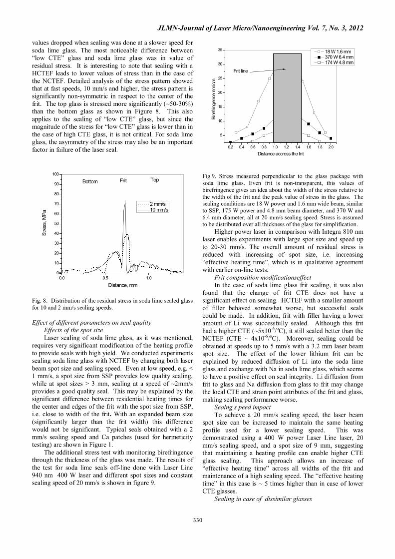
The additional stress test with monitoring birefringence through the thickness of the glass was made. The results of the test for soda lime seals off-line done with Laser Line 940 nm 400 W laser and different spot sizes and constant sealing speed of 20 mm/s is shown in figure 9.
0.2 0.4 0.6 0.8 1.0 1.2 1.4 1.6 1.8 2.0
5
10
15
20
25
30
35
Bire
fring
ence
nm
/cm
Distance accross the frit
18 W 1.6 mm 370 W 6.4 mm 174 W 4.8 mm
Frit line
Fig.9. Stress measured perpendicular to the glass package with soda lime glass. Even frit is non-transparent, this values of birefringence gives an idea about the width of the stress relative to the width of the frit and the peak value of stress in the glass. The sealing conditions are 18 W power and 1.6 mm wide beam, similar to SSP, 175 W power and 4.8 mm beam diameter, and 370 W and 6.4 mm diameter, all at 20 mm/s sealing speed. Stress is assumed to be distributed over all thickness of the glass for simplification.
Higher power laser in comparison with Integra 810 nm laser enables experiments with large spot size and speed up to 20-30 mm/s. The overall amount of residual stress is reduced with increasing of spot size, i.e. increasing “effective heating time”, which is in qualitative agreement with earlier on-line tests. Frit composition modificationseffect In the case of soda lime glass frit sealing, it was also found that the change of frit CTE does not have a significant effect on sealing. HCTEF with a smaller amount of filler behaved somewhat worse, but successful seals could be made. In addition, frit with filler having a lower amount of Li was successfully sealed. Although this frit had a higher CTE (~5x10⁻⁶/oC), it still sealed better than the NCTEF (CTE ~ 4x10⁻⁶/oC). Moreover, sealing could be obtained at speeds up to 5 mm/s with a 3.2 mm laser beam spot size. The effect of the lower lithium frit can be explained by reduced diffusion of Li into the soda lime glass and exchange with Na in soda lime glass, which seems to have a positive effect on seal integrity. Li diffusion from frit to glass and Na diffusion from glass to frit may change the local CTE and strain point attributes of the frit and glass, making sealing performance worse. Sealng s peed impact To achieve a 20 mm/s sealing speed, the laser beam spot size can be increased to maintain the same heating profile used for a lower sealing speed. This was demonstrated using a 400 W power Laser Line laser, 20 mm/s sealing speed, and a spot size of 9 mm, suggesting that maintaining a heating profile can enable higher CTE glass sealing. This approach allows an increase of “effective heating time” across all widths of the frit and maintenance of a high sealing speed. The “effective heating time” in this case is ~ 5 times higher than in case of lower CTE glasses. Sealing in case of dissimilar glasses

JLMN-Journal of Laser Micro/Nanoengineering Vol. 7, No. 3, 2012
331
Sealing of dissimilar glasses is interesting from understanding the limits of possible glass parameters mismatch. From practical point of view sealing of glasses with different properties also important since it creates to reduce cost of the package for display type applications, i.e. use soda lime cover glass in OLED display. Glass strain point effect.
We studied sealing of dissimilar glasses with properties different from Eagle XG ™ and soda lime glass was also investigated, summarized in Table 1 The results are summarized in Table 2. Sealing of Eagle XG ™ glass with 7058 and 9753 Corning glasses shows the importance of strain point: lower strain point glasses seal better. This can be understood by looking at values of the stress. For a high strain point the overall stress will be higher than glass with the same CTE but lower strain point because stress is developing below the strain point of the glass. If the sealing temperature is lower than the strain point of the glass, then the stress value will be the same for glasses with the same CTE. If the strain point is lower than the sealing temperature, the stress will be lower for low strain point glass.
Table 1. Physical properties of glass used in the study.
Glass type CTE 10-7 /°C
Strain point, °C
Anneal point, °C
Eagle XG ™
32 666 725
Soda lime 89 511 545 7058 51 472 512 9753 59 802 837 0211 74 508 550 Table 2. Sealing results summary for different laser
parameters.
Glass sealed pair Sealing speed, mm/s,
Laser spot size, mm
Seal quality
Eagle XG ™/Eagle XG ™
20 1.8 good
Soda lime/soda lime 2 5.0 good Eagle XG ™/7058 20 1.8 good Eagle XG ™/9753 2 and 20 1.8 Didn’t
seal
Eagle XG ™/0211 (75, 150 um)
20 1.8 good
Eagle XG ™/0211 (0.45 mm)
20 1.8 cracks
Soda lime/ soda lime(reduced Li frit)
5 3.2 good
Soda lime/soda lime (reduced Li frit)
20 9 good
This is the case for 7058 and 9753 Corning glasses.
Glass Corning 7058 with a 472°C strain point seals well to Eagle XG ™ glass, while 9753 Corning glass with a similar CTE but a strain point above 800°C doesn’t seal due to delamination. Glass thickness effect
The thickness of the glass also plays an important role, as shown when sealing 0211 Corning glass having a CTE of 8x10⁻⁶/°C and a strain point of about 500°C. Corning
0211glass with a thickness of 150 µm can be sealed to Eagle XG ™ glass, while thicker glass, e.g. > 400 µm, develops cracks and delamination under standard sealing conditions. These experiments were done with standard frit. Additional experiments with soda lime glass also showed that sealing thick glass, e.g. 2 to 3 mm vs. 0.7 mm, produces lower sealing yields, as non-uniform heating of the glass was more pronounced for the thicker glass at fast sealing speeds. Numerical modeling As seen from the above, the key to understanding the nature of the stress profile of a composite glass-frit system is its thermal history from laser heating. We performed numerical simulations of the system to determine how the system’s temperature field evolves. Although a detailed description of the simulations will be reported elsewhere, briefly, and as seen in Figure 10, the glass-frit system was modeled in 2-dimensions, with the dimensions oriented along the line of travel of the laser and the cross-section of the glass-frit system.
Fig 10. Schematic of the system for numerical simulations. Each glass plate thickness is 0.7 mm, frit thickness is 14 microns. The heat source form laser is CW, and frit is only absorbing material in the package, glass absorption and reflection on frit –glass interface are low due to close refractive index matching. The energy transport equation (Fickian diffusion of heat) was solved using an input source for the laser that provided the entire laser power in the frit for a thickness of a few microns from the top glass. The absorption of the frit is relatively high, with 95 % of the power to be absorbed in the 14 um thickness. The glass plates thickness is 0.7 mm. The location of the heat source changed in time along the line of the laser, mimicking its motion, laser spot size is Gaussian with 1.8 mm diameter. Appropriate thermal properties of the frit were considered in the computations. We note that these computations provide a very good qualitative picture of the thermal history of the frit sealing process, but we do not consider them quantitatively exact. Significant uncertainties will exist in any numerical model and our discussion accounts for this.
First, Figure 11 shows the time-temperature history at the interface between the frit and the top glass for different sealing conditions.

JLMN-Journal of Laser Micro/Nanoengineering Vol. 7, No. 3, 2012
332
Fig. 11. Time-temperature history at the interface of the frit and top glass at the center of the frit line, for different laser speeds and power. Arrow indicates the change of the conditions for each curve ordering in the increase of temperature in “cooling” time regime. Spot size is 1.8 mm.
There is temperature distribution across the frit line, but we show only data at the center of the frit line, We clearly see the impact of laser speed and power on the peak temperature at the frit interface: the higher the power or lower the speed, the higher the peak temperature. Approximate temperature measurements of the frit surface showed peak temperature to be close to 520 °C, what is in reasonable agreement with calculated temperature. The test was done using fast speed pyrometer (operation wavelength ~ 1800 nm within transparency of the glass, but not the frit), looking at the moving sealing spot during sealing process as described in details in [16]. Two aspects of the time-temperature profile merit discussion. The first is when the stress arising from thermal expansion sets into the glass. For a first-cut analysis, we can assume the period before the glass reaches peak temperature does not contribute to the stress. This is due to the fact that after glass reached temperature above strain pint the stress is relaxed, however surrounding material, which doesn’t heat above strain point may accumulate stress. In the period after the peak temperature is attained, we see that faster laser speeds (20 mm/s) have a much higher cooling rate on the glass and frit, as seen by the steepness of the curve. Slower speeds may mitigate this by cooling the material slower, thus reducing the stress. Another way of reducing this cooling rate is to increase the spot size of the beam, which will produce results qualitatively similar to a slower speed. We observe this exact result in experiments, as mentioned earlier. We note here that our thermal profile for a sealing speed of 20 mm/s produces a peak temperature that is barely at the frit melting point, but the qualitative message that can be drawn remains unchanged. This is one of the areas where a lack of information on the model’s accuracy prevents its quantitative usage. The second aspect of the time-temperature profile we discuss is whether there is a stress due to mismatch between the CTE of the frit and glass. If this is the case, such stress can only arise after the frit temperature is lower than its melting point. This would imply that a stress mismatch would depend only on the thermal history once the temperature cooled below the frit melting point. The
cooling rate is at the same order of magnitude for laser speeds between 20 and 2 mm/s once the material has cooled to around 200 Kelvin less than the peak temperature. In most cases this corresponds to the regime where the frit will again become solid, implying that laser speed has only a small impact on mismatch-induced stress. In our experiments we find that different frit CTEs with a range of 3.2 to 5x10⁻⁶/°C don’t affect the sealing process for both Eagle XG ™ and soda lime glass. In any case, the frit is a composite substance, with islands of filler and glass having vastly different CTEs. The particle sizes are a few microns each, while the frit thickness is 15 micron. It is unclear whether the frit behaves as a homogeneous body with a single CTE under these conditions, putting some uncertainty into the mismatch hypothesis. Discussion and conclusions. Overall, laser sealing of soda lime-type glass with a frit designed for OLED sealing NCTEF generates significant cracking and delamination of the frit. Even if the glass-frit system can be sealed under standard conditions, the yield is very low [18]. It was shown that laser sealing with a standard beam spot size and slow speed provides better results, but yields were still very low. An analysis shows the high residual stress in the glass is principally responsible for the failure, and that transient stresses are not that different in moderate and high CTE glasses. Reduction of the stress can be managed by elevating the ambient temperature or by changing the heating profile as it was suggested in [18]. Laser sealing of soda lime glass requires significant modification of the heating profile to provide seals with high yield. Samples of soda lime glass sealed with an expanded beam, i.e. longer “effective heating time” than SSP (5 mm diameter and 2 mm/s sealing speed, for example) successfully passed an exposure of 1000 hours test in an 85°C/85% RH environmental chamber. In this case “effective heating time” is increased by 25 times in comparison to SSP. These changes also lead to reduction of the cooling rate, responsible for residual stress. However, even for 5 times increase relative to SSP, successful seals for soda lime glass can be obtained. In the case of soda lime glass frit sealing, it was also found that frit CTE does not have a large effect on sealing. Higher CTE frit with a smaller amount of filler behaved somewhat worse, but successful seals could still be made. Again, sealed samples passed a 1000 hour 85°C/85% RH environmental chamber test for 80/20 and HCTEF, i.e. 90/10 glass/filler ratio frits. It was also shown that frit with filler having lower amount of Li produces improved sealing results.
Frit properties such as CTE seem not to be that critical due to the low thickness of the frit (~15 µm). However, the strain point of the glass is important. Matching the CTEs for frit and glass is not that critical, and glass-frit mismatches as high as ~ 5x10⁻⁶/oC can be successfully accommodated. To achieve a 20 mm/s sealing speed, the laser beam spot size can be increased to maintain the same heating profile as used for lower sealing speed. This was demonstrated with a laser power of 400 W, 20 mm/s

JLMN-Journal of Laser Micro/Nanoengineering Vol. 7, No. 3, 2012
333
traverse speed, and a spot size of 9 mm, suggesting that maintaining the heating profile can enable higher CTE glass sealing without compromising the sealing speed.
The sealing of dissimilar glasses with properties different from Eagle XG ™ and soda lime was investigated. The sealing of Eagle XG ™ glass with 7058 and 9753 Corning glasses shows the importance of strain point: The lower strain point glasses seal better. Increasing the CTE requires an increase of the cooling time to maintain a similar strain. The glass stress level depends on both the CTE of the glass and its strain point. Lower strain point glasses with the same CTE can be sealed with a shorter “effective heating time” than that needed for higher strain point glasses. The same is applicable to CTE levels: The higher the CTE and strain point of the glass, the more difficult sealing becomes. This requires more elongated heating profile, which requires more laser power due to increased of laser spot size and slower sealing speed.
Dissimilar glasses can be sealed, and CTE mismatches up to 2x10⁻⁶/oC with a NCTEF was demonstrated. The thickness of the glass being sealed plays a critical role, with thinner glass being easier to seal than thicker glasses. The glass thickness starts to play a role when the heat diffusion distance becomes comparable to the thickness of the glass.
These experimental findings are supported by numerical modeling results. Acknowledgements We would like to thank James Price for measuring our reference samples and consultation during construction of birefringence setup, Xinghua Li for help in laser scoring soda lime samples for birefringence analysis, and Kevin Able for help with paper editing. References: [1]“OLED Encapsulation”, Information Display Jul. 2002, p. 26-28. [2] M. L. Boroson, J.P. Serbicki, P.G. Bessey, G.C. Irvin, L.A. Rowley, C.J. Kaminsky, “Desiccants and desiccant packages for highly moisture-sensitive electronic devices”, US patent application 2003/0037677A [3] A. P. Ghosh, L. J. Gerenser, C. M. Jarman, J. E. Fornalik, “Thin-film encapsulation of organic light-emitting devices”, Appl. Phys. Lett. 86, 223503 (2005) [4] B.G. Aitken, P.S. Danielson , J. E. Dickinson, S.L. Logunov, R. Morena, M.L. Powley, K.P. Reddy, J.F. Schroeder, A. Streltsov, Hermetically sealed glass package and method of fabrication US Patent 8148179B2 [5] I. Miyamoto, A. Horn, J. Gottmann, D. Wortmann and F. Yoshino., J. Laser Micro Nanoeng. 2, 57 (2007) [6] W. Watanabe .S. Onda, T. Tamaki, K. Itoh, Appl. Phys. Lett. 89, 021106 (2006)
[7] S. Richter, S. Döring, A. Tünnermann, S. Nolte Appl. Phys. A, 103, 257, (2011) [8] B.G. Aitken., J.P. Carberry ,S.E. DeMartino, , H.E. Hagy, L.A. Lamberson, R.J. Miller, R. Morena, J.E. Schroeder, A. Streltsov, S. Widjaja “Glass package that is hermetically sealed with a frit and method of fabrication.”- US Patent 6,998,776 [9] R. M. Morena, L. A. Lamberson, S. Widjaja and S. L. Logunov “Frit-sealing at high heating and cooling rate”, 6th Pacific Rim Conference on Ceramic and Glass Technology, Sep. 11–16, 2005, Hawaii US [10] K.J. Becken, S.L Logunov. KP Reddy, J.F. Schroeder, H.J. Strzepek “Optimization of parameters for sealing organic emitting light diode (OLED) displays” US Patent 7,371,143 [11].S. Widjaja, J. F. Bayne, S. H. Carley, R. and M. Morena, “Integrity of frit sealed thin glass substrate assembly”, 6th Pacific Rim Conference on Ceramic and Glass Technology, Sep. 11–16, 2005, Hawaii US [12] US20070128967A “Method of making a glass envelope”, by K. Becken and S. Logunov [13] US20070128966A “Method of encapsulating display element”, by K. Becken and S. Logunov [14].K. Becken, S. Logunov, K.P. Reddy, J. Schroeder, H. Strzepek “Optimization of parameters for sealing organic emitting light diode (OLED) displays, UU7,371,143 B2, May, 2008 [15] S. Logunov, J. Lorey, V. Schneider “ Method and apparatus for packaging electronic components” US7,815,480B2, October, 2010. [16] C. Lai, S. Logunov, J. Lorey, V. Schneider, “Quality control of the frit for OLED sealing” US20100118912A1, May 2010 [17] MLH. Tardy, "An Experimental Method for Measuring the Birefringence in Optical Materials," Opt. Rev. 8,59-69 (1929). [18] L. Zhang, S.Logunov, K. Becken, M. Donovan, B. Vaddi, Impacts of Glass Substrate and Frit Properties on Sealing for OLED Lighting, SID Symposium Digest of Technical Papers -- May 2010 -- Volume 41, Issue 1, pp. 1890-1893
(Received: May 19, 2012, Accepted: July 17, 2012)