Embed Size (px)
Citation preview

White Paper
Large SAN Design Best Practices using MDS 9710 and MDS 9500 Multilayer Director Switches
Introduction
As storage area networks (SANs) continue to grow in size, many factors need to be considered to help scale
and manage them. This paper focuses on large SAN deployments within a data center, and provides best
practices and design considerations when designing a large physical fabric. It does not address networks
implementing Inter-VSAN Routing (IVR), FC or FCIP based SAN extension, or intelligent fabric applications
(for example, Data Mobility Manager, or IO Acceleration (IOA)).
Design Parameters
In SAN environments there are many design criteria that needs to be addressed, such as performance, high
availability and scalability. This document focuses on the following design parameters:
1000 or more end devices (servers, storage, and tape devices)
Majority of end devices with connection speeds of 4G, 8G, or 16G
Identical dual physical fabrics (Fabric-A, Fabric-B)
SAN is already in production using MDS 9500 series director class switches.
Network Considerations
When designing a large Cisco MDS fabric, the following should be taken into consideration:
Ports and Port Groups
Dedicated and Shared mode
Port Speed
ISLs
Port Channels
8-Gbps versus 10-Gbps Fibre channel ISLs
Fan-in, Fan-out and Oversubscription ratio
Type of zones
Smart Zoning
VSANs
Fabric logins and Scalability
Ports and Port Groups:
Each port in Cisco MDS 9000 family is a member of one port group that shares common resources from
assigned pool of allocated bandwidth. This allows the appropriate bandwidth allocation for high bandwidth
and low bandwidth devices, The table below has some of the details needed to better understand bandwidth
allocation per port and port group for switching modules that we will consider in this paper.

Part number Product Name No. of Port
Groups No. of Ports
per Port Group BW Per Port Group
(Gbps)
DS-X9248-256K9 48-port 8-Gbps
Adv FC module 8 6 32.4
(1) 12.8
(2)
DS-X9232-256K9 32-port 8-Gbps Adv FC module
8 4 32.4 (1)
12.8 (2)
DS-X9248-96K9 48-port 8-Gbps FC module
8 6 12.8 (3)
DS-X9224-96K9 24-port 8-Gbps FC module
8 3 12.8 (3)
DS-X9448-768K9 48-port 16-Gbps 12 4 64 (4)
Table 1: Bandwidth and Port group configurations for Fibre channel modules.
(1)
MDS 9513 with Fabric 3 Module installed
(2)
MDS 9506 (all) and MDS 9509 (all) or MDS 9513 with Fabric 2 Module installed
(3)
MDS 9506 (all), MDS 9509 (all) or MDS 9513 (all)
(4)
MDS 9710 (all)
Dedicated and Shared rate mode:
Ports on MDS 9000 series line cards are grouped into port-groups that have a fixed amount of bandwidth per
port-group (see Table 1). The MDS 9000 family allows for the bandwidth of ports within a port group to be
allocated based on the requirements of individual ports. When planning port bandwidth requirements,
allocating the bandwidth within the port-group is important. Ports with the port group can have bandwidth
dedicated to them or ports can share a pool of bandwidth. Ports that require high sustained bandwidth, for
example, ISL ports, storage/tape array ports, high bandwidth servers, can have bandwidth dedicated to them
within a port group using the switchport rate-mode dedicated command. Other ports, typically servers that
access shared storage array ports (that is, storage ports that have higher fan-out ratios), can share the
bandwidth within a port group by using the switchport rate-mode shared command. When configuring the
ports, it is important not to exceed the available bandwidth within a port group.
As an example, a MDS 9513 with a fabric 3 module installed and using a 48-port 8-Gbps Advanced FC
module has eight port groups of 6 ports each. Each port group has 32.4 Gbps of bandwidth available. It would
not be possible to configure all 6 ports of a port group as 8 Gbps dedicated rate since that would require 48
Gbps of bandwidth and the port group only has 32.4 Gbps of bandwidth. It is possible to configure all 6 ports
in shared rate mode, meaning that the ports would run at 8 Gbps and will be over-subscribed at a rate of
1.48:1 (6 ports * 8Gbps = 48 Gbps / 32.4 Gbps). This is an over-subscription rate well below the over-
subscription rate of the typical storage array port (fan-out ratio) and does not impact performance.
It is possible to mix dedicated and shared rate ports within a port group. Using the same environment as
before, one port in the port group can be configured for dedicated 8 Gbps of bandwidth and be used as an
ISL port or a storage target port. This will allocate 8 Gbps of the port group bandwidth to the dedicated rate
mode port leaving 24.4 Gbps of bandwidth for the remaining 5 ports to be shared, giving them an
oversubscription ratio of 1.64:1 (5 ports * 8 Gbps = 40 Gbps / 24.4).
Port Speed:
The speed of an interface, combined with rate mode, determines the amount of shared resources available to
the ports in the port group. The speed of an interface can be configured to automatically detect the speed of
the attached device or it can be explicitly configured. When a port is configured for auto speed detect, the
switch assumes it is capable of the highest speed allowed by that port, dependent on the type of line card
module is being used. This means that port bandwidth may be allocated for a higher speed that the attached
device requires. For maximum use of bandwidth within a port group, it is recommended to explicitly specify
the port speed of the attached device.

Inter-Switch Links (ISLs)
Inter-Switch Link (ISL) is the term used to describe the connection between Fibre channel switches. The
number of ISLs required between Cisco MDS switches will depend on the desired end-to-end
oversubscription ratio. The storage port oversubscription ratio from a single storage port to multiple servers
can be used to determine the number of ISLs needed for each edge-to-core connection. In the diagram below
(Figure 1), there are 3 examples of different storage, server and ISL combinations, all with the same
oversubscription ratio of 8:1. The first example has one 16-Gbps storage port with eight 16-Gbps server ports
going over one 16-Gbps ISL. The second example has one 16-Gbps storage port with sixteen 8-Gbps server
ports going over one 16-Gbps ISL. The third example has eight 16-Gbps storage port with sixty-four 16-Gbps
server ports going over eight 16-Gbps ISLs in the ideal world, maintaining a 1:1 ratio of storage bandwidth to
ISL bandwidth is recommended for SAN design but that is not the case most of the time because of reasons
like resource efficiency and allocation. When we design the SAN network, we usually want to make sure that
the oversubscription ratio is minimal with enough room to support growth. We should also make sure to have
additional ISL bandwidth availability to provide higher availability in case of link failure.
Figure 1: Number of ISLs Needed to Maintain Oversubscription Ratio
PortChannels:
PortChannels refer to the aggregation of multiple physical interfaces into one logical interface to provide
higher aggregated bandwidth, load balancing, and link redundancy while providing fabric stability in event of
member failure. PortChannels can connect to interfaces across different switching modules, so a failure of a
switching module cannot bring down the PortChannel link.
A PortChannel has the following functionality:
Provides a single logical point-to-point connection between switches
Provides a single VSAN ISL (E port) or trunking of multiple VSANs over an EISL (TE port). EISL ports
are only between Cisco switches and carries traffic for multiple VSANs compared to ISL.
Increases the aggregate bandwidth on an ISL by distributing traffic among all functional links in the

channel. PortChannels may contain up to 16 physical links and may span multiple modules for added
high availability. Multiple Port channels can be used if more than 16 ISLs are required between
switches.
Load balances across multiple links and maintains optimum bandwidth utilization. Load balancing is
based on per VSAN configuration (Source ID / Destination ID (SID/DID) or Source ID / Destination ID /
Exchange ID (SID/DID/OXID)).
Provides high availability on an ISL. If one link fails, traffic is redistributed to the remaining links. If a link
goes down in a PortChannel, the upper protocol is not aware of it. To the upper protocol, the link is still
there, although the bandwidth is diminished. The routing tables are not affected by link failure.
8-Gbps FC and 10-Gbps Fibre Channel ISLs:
The Fibre Channel protocol is typically associated with the 1/2/4/8/16 Gbps speeds of attached devices.
However, the Fibre Channel protocol also supports 10 Gbps which can be used for ISLs. The use of 8 Gbps
or 10 Gbps ISLs is a significant design consideration when 16 Gbps interfaces are not available.
At first glance, 10 Gbps Fibre Channel appears to be only a 25% increase over 8 Gbps Fibre Channel.
However, due to the differences of the physical layer, 10 Gbps Fibre Channel actually has a data rate 50%
greater than 8 Gbps Fibre Channel. To understand this, one must look at the way data is transmitted over the
two interfaces. All data is encoded is used to ensure data integrity when transmitted over an interface. For 8
Gbps FC, for every 8 bits of data, 10 bits are transmitted, imposing a 25% overhead. For 10 Gbps FC, for
every 64 bits of data, 66 bits are transmitted, an overhead on only 3.125%. This encoding combined with the
physical clock rate determines the actual data rate of the interface.
FC Interface
Speed
Clock Rate Data Encoding Data Rate
(Gbps)
Data Rate
(MB/s)
8 Gbps 8.5 Gbps 8b/10b 6.8 Gbps 850 MB/s
10 Gbps 10.51875 Gbps 64/66b 10.2 Gbps 1275 MB/s
When designing ISLs connectivity, 10-Gbps FC interfaces can provide greater bandwidth per ISL or reduce
the number of ISLs between switch, reducing the amount of cabling required.
Different line card modules have their own port group settings. Depending upon the port group configuration,
we can configure that port for regular 1/2/4/8/16 FC speeds or 10-Gbps FC speed. Please note that
depending on the specific line card module, not all the ports can be configured for 10-Gbps FC speed.
Figures 2 and 3 below shows the specific ports of the individual port groups that can be configured for 10-
Gbps FC speed. The interfaces that can be configured out of the port groups are identified within the Yellow
border and the ones that will be disabled by switch at marked with Red Cross “X”. Only the first two port
groups are shown, however the groupings of ports are the same for the remainder of the port groups.
Figure 2: 10-Gbps FC port selection in DS-X9248-256k9

Figure 3: 10-Gbps FC port selection in DS-X9232-256k9
For the DS-X9448-768K9, 16-Gbps 48-port line card module, All ports in paired port groups can operate in
either 2/4/8/16-Gbps mode or 10-Gbps mode. This means that 10-Gbps is enabled in 8-port increments at
port group level (ports 1-8, 9-16, 17-24, 25-32, 33-40 and 41-48). If we enable 10-Gbps speed, it will be
enabled for all interfaces in those two pair of port groups as mentioned above.
Fan-in, Fan-out and Oversubscription ratio:
To efficiently and optimally use resources and to save deployment and reduce management costs, SANs are
designed to share Array ports, ISL and line card bandwidth. The terms used to describe this sharing include
Fan-in ratio, Fan-out ratio and Oversubscription ratio. Which term is used depends on the point of reference
being described. Generally speaking, Fan-in ratio is calculated as the ratio of host port bandwidth to storage
array port bandwidth and Fan-out ratio is calculated as the ratio of storage array port bandwidth to host port
bandwidth. Oversubscription is a networking term that is generally defined as the overall bandwidth ratio
between host and storage array ports. See Figure 4 below for more details.
Figure 4: Fan-In; Fan-Out and Oversubscription ratios
Zones
Within each VSAN, there is only one active zoneset that contains one or more zones. Each zone consists of
one or more members to allow for communication between the members. The Cisco MDS SAN-OS and NX-
OS provide multiple ways to identify zone members, but the commonly used ones are:
● pwwn: Port World-Wide Name of the device (most commonly used)

● device-alias: An easy-to-read name associated with a single device’s Port World-Wide Name (pwwn)
Depending on the requirements of the environment, choosing the type of zone members is a matter of
preference. A recommended best practice is to create a “device-alias” for end devices when managing the
network. The device-alias provides an easy-to-read name for a particular end device. For example, a storage
array with a pwwn 50:06:04:82:bf:d0:54:52 can be given a device-alias name of Tier1-arrayX-ID542-Port2. In
addition, with device-alias, when the actual device moves from one VSAN (VSAN 10) to a new VSAN (VSAN
20) in the same physical fabric, the device-alias name will follow that device. So there is no need to re-enter
the device-alias for each port of the moved array in the new VSAN.
Note: As a best practice for large SAN deployments, it is recommended to have more zones with two-member
zones versus a single zone with three or more members. This is not a concern in smaller environments where
managing zones is much easier but when the SAN network starts expanding and growing, it is better to
implement Smart Zoning to manage the SAN network easily.
Smart Zoning:
Smart zoning supports zoning multiple devices in a single zone by reducing the number of zoning entries that
needs to be programmed. This means that multiple member zones consisting of multiple initiators and
multiple zones can be zoned together without increasing the size of the zone set. Smart zoning can be
enabled at the zone level, zone set level, zone member, or at the VSAN level.
Virtual SANs (VSANs)
Cisco MDS switches offer VSAN technology, which is a simple and secure way to consolidate many SAN
islands into a single physical fabric. Separate fabric services (i.e. per VSAN zoning, Name Services, Domains
and separate role base management) are provided for each VSAN, providing separation of both the control
plane and the data plane.
There are multiple use cases for VSANs, such as creating a VSAN for each type of operating system (i.e.
VSAN for Windows or HP-UX), or utilizing them on the basis of business functions (i.e. a VSAN for
development, for production, or for a lab). VSAN 1 is created on the Cisco MDS switch by default and cannot
be deleted. As a best practice, VSAN 1 should be used as a staging area for un-provisioned devices and
other VSAN(s) should be created for the production environment(s). With each VSAN having its own zones
and zone-sets, Cisco MDS switches enable secure, scalable and robust networks. One of the use case of
multi-tenancy is when there are multiple customers using SAN with strict requirements around traffic
segmentation.
Fabric logins and Scalability
When a Fibre channel switch wants to forward traffic to its neighbouring switch or host connector, it needs to
interchange the login parameters. These parameters are called Fabric Logins. Each switch has some
limitation on how many Fabric logins can be allowed at any single time. Generally, the number of actual
physical ports in the fabric is larger than the number of end devices (server, storage, and tape ports) in the
physical fabric. The Cisco MDS Family supports enough number of fabric logins in a physical fabric,
independent of the number of VSANs in the network for today’s network. Typically when designing a SAN, the
number of end devices determines the number of fabric logins. The increase in blade server deployments and
the consolidation of servers due to server virtualization technologies, will affect the design of the network.
With features such as N_Port ID Virtualization (NPIV) and Cisco N_Port Virtualization (NPV), the number of
fabric logins has further increased (Figure 5). The proliferation of NPIV-capable end devices such as host bus
adaptors (HBAs) and Cisco NPV-mode switches makes the number of fabric logins on a per-port, per-line-
card, per-switch, and per-physical-fabric basis a critical consideration. These fabric login limits will determine
the design of the current SAN, as well as future growth. The total number of hosts and NPV switches will
determine the fabric logins required on the core switch. In the recent times, it is difficult to control the virtual
machines hosted on servers so it is important to plan ahead and keep some reservations on the resources
side. The current scalability numbers for MDS product line can be found under Configuration Guides. To
estimate the number of Flogis requirement for the SAN network we can use the formula: (# of hosts) x (# of
initiators per host).

Figure 5: Cisco NPV-Enabled Switches and Fabric Logins
Note: Prior to NPIV and NPV, a single port had a maximum of one fabric login. With NPIV and Cisco NPV-
enabled switches, a single port can now support multiple fabric logins.
Cisco MDS 9500 and MDS 9700 components
In this white paper, we will specifically talk about the best options to install Cisco MDS 9710 Director Class
switch at the core with existing SAN network running MDS 9513s at Edge / Core. The Cisco MDS 9513
provides multiple line card options. We will talk about four of the mostly used and deployed line cards
supported under MDS 9513 as mentioned below. Also, we are using Fabric-3 module (DS-13SLT-FAB3) with
MDS 9513 to give us 256-Gbps of fabric switching throughput per slot. The Cisco MDS 9710 has a 48 port
16-Gbps line card module that we are going to use with MDS 9710 chassis. . This module offers hardware
based slow drain, real time power consumption reporting and improved diagnostics capabilities.
1. Cisco MDS 9513 Multilayer Director: DS-C9513
Cisco MDS 9513 is a director-class multilayer series switches to help large scale enterprises and service
provides to help design and deploy large scale data centers, scalable enterprise clouds to enable business
transformation. The Cisco MDS 9513 is a 13-slot director in a 14RU form factor. Two slots are reserved for
the redundant Supervisor Modules and the eleven remaining slots are available for line card and service
modules. It can support maximum 528 ports per chassis or 1152 ports per rack with total through-put of 8.4-
Tbps per chassis. It can provide 1/2/4/8 and 10-Gbps Fibre Channel (FC), 10-Gbps Fibre Channel over
Ethernet (FCoE), and 1/2/4/8/10-Gbps FICON interfaces.
2. Cisco MDS 9710 Multilayer Director: DS-C9710
The Cisco MDS 9710 is the newest generation director-class multilayer series switch. It can support up to 384
line-rate 16-Gbps Fibre Channel or 10G FCoE ports. The Cisco MDS 9710 comes with dual supervisor
modules and with six fabric modules provides up to 24-Tbps chassis throughput.
The Cisco MDS 9700 48-Port 16-Gbps Fibre Channel switching module delivers line rate non-blocking 16-
Gbps FC performance to enable scalability in the virtualized data centers. Line-rate 16-Gbps performance
provides high bandwidth throughput for consolidation of workloads from thousands of virtual machines while
reducing SAN components, providing scaling with future SAN growth at the same time. These line card
modules are hot-swappable and continue to provide all previous Cisco MDS features like predictable
performance, high availability, advanced traffic management capabilities, Integrated VSANS, high-
performance ISLs, fault detection, isolation of errored packets and sophisticated diagnostics. This module
offers new hardware based slow drain, real time power consumption reporting and improved diagnostics
capabilities. The Cisco MDS 9710 can support up to 384 line-rate 16-Gbps Fibre Channel line-rate throughput
along with 10G FCoE. IT comes with dual supervisor modules and we can have 8 switching module line cards
to provide total of 24-Tbps chassis throughput with the help of 2/4/8/10/16-Gbps FC or 10-Gbps FCoE ports.
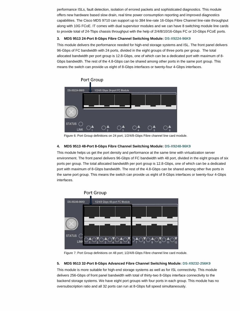
3. MDS 9513 24-Port 8-Gbps Fibre Channel Switching Module: DS-X9224-96K9
This module delivers the performance needed for high-end storage systems and ISL. The front panel delivers
96-Gbps of FC bandwidth with 24 ports, divided in the eight groups of three ports per group. The total
allocated bandwidth per port group is 12.8-Gbps, one of which can be a dedicated port with maximum of 8-
Gbps bandwidth. The rest of the 4.8-Gbps can be shared among other ports in the same port group. This
means the switch can provide us eight of 8-Gbps interfaces or twenty-four 4-Gbps interfaces.
Figure 6: Port Group definitions on 24 port; 1/2/4/8-Gbps Fibre channel line card module.
4. MDS 9513 48-Port 8-Gbps Fibre Channel Switching Module: DS-X9248-96K9
This module helps us get the port density and performance at the same time with virtualization server
environment. The front panel delivers 96-Gbps of FC bandwidth with 48 port, divided in the eight groups of six
ports per group. The total allocated bandwidth per port group is 12.8-Gbps, one of which can be a dedicated
port with maximum of 8-Gbps bandwidth. The rest of the 4.8-Gbps can be shared among other five ports in
the same port group. This means the switch can provide us eight of 8-Gbps interfaces or twenty-four 4-Gbps
interfaces.
Figure 7: Port Group definitions on 48 port; 1/2/4/8-Gbps Fibre channel line card module.
5. MDS 9513 32-Port 8-Gbps Advanced Fibre Channel Switching Module: DS-X9232-256K9
This module is more suitable for high-end storage systems as well as for ISL connectivity. This module
delivers 256-Gbps of front panel bandwidth with total of thirty-two 8-Gbps interface connectivity to the
backend storage systems. We have eight port groups with four ports in each group. This module has no
oversubscription ratio and all 32 ports can run at 8-Gbps full speed simultaneously.

Figure 8: Port Group definitions on 32 port; 1/2/4/8/10-Gbps Fibre channel line card module.
6. MDS 9513 48-Port 8-Gbps Advanced Fibre Channel Switching Module: DS-X9248-256K9
With 8-Gbps FC bandwidth option, this module is more suitable for port-density at high speed performance.
The front panel delivers 256-Gbps of FC bandwidth with 48 port, divided in the eight groups of six ports per
group. The total allocated bandwidth per port group is 32-Gbps with maximum speed of 8-Gbps per port.
Figure 9: Port Group definitions on 48 port; 1/2/4/8/10-Gbps Fibre channel line card module.
7. MDS 9700 48-Port 16-Gbps Fibre Channel Switching Module: DS-X9448-768K9
The Cisco MDS 9700 48-Port 16-Gbps Fibre Channel switching module is the best of class with new chassis
to deliver line rate 16-Gbps FC performance to enable scalability in the virtualized data centers. MDS 9710
can have up to 384 line-rate 16-Gbps Fibre Channel ports per chassis. These line card modules are hot-
swappable and compatible with 2/4/8/10 and 16-Gbps FC interfaces.
Figure 10: Port Group definitions on 48 port; 2/4/8/10/16-Gbps Fibre channel line card module for MDS 9710.

SAN Topology Considerations
It is common practice in SAN environments to build two separate, redundant physical fabrics (Fabric A and
Fabric B) in case a single physical fabric fails. For this document, we are showing a single fabric in the
topology diagrams however customers would deploy two identical fabrics for redundancy. When designing for
large networks, most environments will fall into two types of topologies within a physical fabric:
1. Two-tier: Core-edge design
2. Three-tier: Edge-core-edge design
Within the two-tier design, servers connect to the edge switches, and storage devices connect to one or more
core switches (Figure 11). This allows the core switch to provide storage services to one or more edge
switches, thus servicing more servers in the fabric.
Figure 11: Sample Core-Edge Design
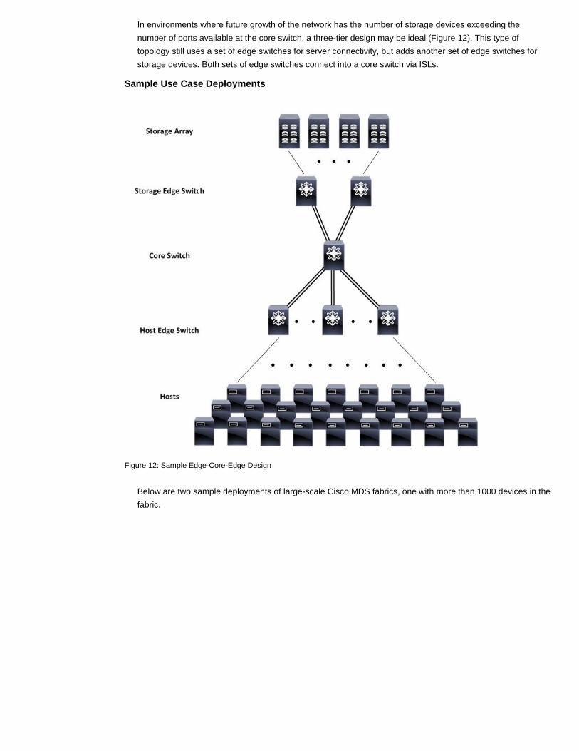
In environments where future growth of the network has the number of storage devices exceeding the
number of ports available at the core switch, a three-tier design may be ideal (Figure 12). This type of
topology still uses a set of edge switches for server connectivity, but adds another set of edge switches for
storage devices. Both sets of edge switches connect into a core switch via ISLs.
Sample Use Case Deployments
Figure 12: Sample Edge-Core-Edge Design
Below are two sample deployments of large-scale Cisco MDS fabrics, one with more than 1000 devices in the
fabric.

Sample Deployment 1
Figure 13: Use Case 1 Topology
This deployment allows scaling to nearly 3500 devices in a single fabric. The actual production environment
has approximately 128 storage ports running at 16-Gbps of storage devices and roughly 2560 host ports. The
environment required a minimum of 10:1 oversubscription within the network, which required each host edge
switch to have a 2048-Gbps port channel, using 128 physical links (ISLs). Storage ports will not grow quite as
rapidly and the core switch has room to grow to add more host edge switches and connect using ISLs. In this
environment, the following was used in managing the network:
Total of four VSANs created
o VSAN 1 used for staging new SAN devices
o VSAN 100 for Development SAN
o VSAN 200 for Lab SAN
o VSAN 300 for Production SAN
Use of TACACS+ for authorization and authentication of MDS switches
Use of Role-Based Access Control (RBAC) to create separate administrative roles for VSANs
Use of device-aliases logical device identification
Use of two member zones with device-alias

Sample Deployment 2
Figure 14: Use Case 2 Topology
Note: This deployment scales to nearly 3500 devices in a single fabric and still has room to grow for
instance by adding a second core and …… . The actual production environment has 120 storage ports
running at 16-Gbps and 2880 hosts using 8-Gbps FC interfaces.
The environment required a minimum of 12:1 oversubscription within the network, which required each host
edge switch to have a 2016-Gbps port channel on the core side. This will give enough of bandwidth to
performance-hungry applications when needed.
In this environment, the following was used in managing the network:
Total of five VSANs created
o VSAN 1 used for staging new devices
o Four VSANs based upon business operations
Used TACACS+ for authorization and auditing of Cisco MDS switches
Created separate administrative roles for VSANs
Created device-alias for environment
Enabled Dynamic Port VSAN Membership (DPVM) feature
Mixture of two and three member zones
Summary
With data centers constantly growing, SAN administrators can now design networks that meet their current
needs and can scale for demanding growth. Cisco MDS 9710 Multilayer Director Class switches provide
embedded features to help SAN administrators with the redundancy, high availability and performance benefit
at the core level with room to meet the future growth without performance impact. SAN administrators
upgrading / deploying their existing large Cisco SAN fabrics using MDS 9500 can use the design parameters
and best practices discussed in this paper to design optimized and scalable SANs using new MDS 9710.
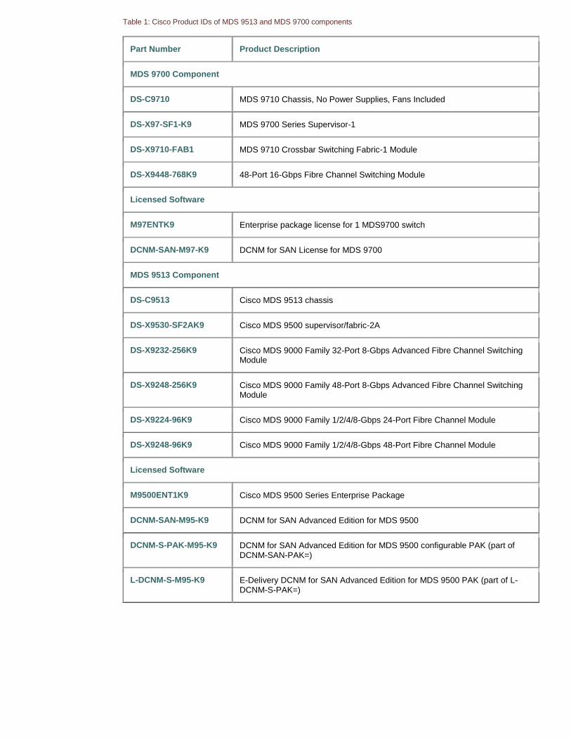
Table 1: Cisco Product IDs of MDS 9513 and MDS 9700 components
Part Number Product Description
MDS 9700 Component
DS-C9710 MDS 9710 Chassis, No Power Supplies, Fans Included
DS-X97-SF1-K9 MDS 9700 Series Supervisor-1
DS-X9710-FAB1 MDS 9710 Crossbar Switching Fabric-1 Module
DS-X9448-768K9 48-Port 16-Gbps Fibre Channel Switching Module
Licensed Software
M97ENTK9 Enterprise package license for 1 MDS9700 switch
DCNM-SAN-M97-K9 DCNM for SAN License for MDS 9700
MDS 9513 Component
DS-C9513 Cisco MDS 9513 chassis
DS-X9530-SF2AK9 Cisco MDS 9500 supervisor/fabric-2A
DS-X9232-256K9 Cisco MDS 9000 Family 32-Port 8-Gbps Advanced Fibre Channel Switching Module
DS-X9248-256K9 Cisco MDS 9000 Family 48-Port 8-Gbps Advanced Fibre Channel Switching Module
DS-X9224-96K9 Cisco MDS 9000 Family 1/2/4/8-Gbps 24-Port Fibre Channel Module
DS-X9248-96K9 Cisco MDS 9000 Family 1/2/4/8-Gbps 48-Port Fibre Channel Module
Licensed Software
M9500ENT1K9 Cisco MDS 9500 Series Enterprise Package
DCNM-SAN-M95-K9 DCNM for SAN Advanced Edition for MDS 9500
DCNM-S-PAK-M95-K9 DCNM for SAN Advanced Edition for MDS 9500 configurable PAK (part of DCNM-SAN-PAK=)
L-DCNM-S-M95-K9 E-Delivery DCNM for SAN Advanced Edition for MDS 9500 PAK (part of L-DCNM-S-PAK=)

Important links:
Cisco MDS 9700 Series documents:
Cisco MDS 9700 Series Multilayer Directors
Cisco MDS 9710 Multilayer Director Data Sheet
Cisco MDS 9700 Series Supervisor-1 Module Data Sheet
Cisco MDS 9700 48-Port 16-Gbps Fibre Channel Switching Module Data Sheet
Compare Models: Learn about the similarities and differences of the models within this product series.
Data Sheets and Literature (4)
At-a-Glance Sheets
Data Sheets
Presentations
White Papers
Cisco MDS 9500 Series documents:
Cisco MDS 9513 Multilayer Director
Cisco MDS 9000 Family 8-Gbps Advanced Fibre Channel Switching Modules (PDF - 440 KB)
Cisco MDS 9000 Family 8-Gbps Fibre Channel Switching Modules (PDF - 210 KB)
Cisco MDS 9500 and 9700 Series Multilayer Directors (PDF - 340 KB)
Cisco MDS 9000 Family 8-Gbps Advanced Fibre Channel Switching Modules
Cisco MDS 9000 Family 8-Gbps Fibre Channel Switching Modules
Cisco MDS 9513 Multilayer Director Data Sheet
Cisco MDS 9000 Family Investment Protection