Embed Size (px)
Citation preview

EA 9710
LOCHHAMER SCHLAG 17 · D-82166 GRÄFELFINGPhone +49-89-8541991 · FAX +49-89-8541721 · lcd-module.de
12.97
RS-232 / RS-485 / CENTRONICSCONTROLLER FOR GRAPHIC MODULES
FOR DIRECT CONNECTION TOBELOW LISTED GRAPHIC MODULES:
FEATURES* SUPPORTS ALL KNOWN LCD- GRAPHIC DISPLAYS (MONOCHROME)* CONNECT EITHER TO RS-232 OR RS 485 OR CENTRONICS OR TO 8-BITBUS* TERMINALMODE VT-52 I.E. 640x400 DISPLAY: 80/40 CHAR., 25/50 LINES* INTELLIGENT GRAPH COMMANDS LIKE DRAW LINE, DELETE, SET DOTS,* DISPLAY WINDOWS, TEXTROTATION IN 90° STEPS* POWER SUPPLY: VDD= + 5V ±5%, approx. 150mA* DISPLAY SELECTION WITH DIP-SWITCHES B* KEYBOARDCONNECTION: MF-102 OR 8x8 MATRIX (RS-232 AND RS 485ONLY)* INTERFACE PARAMETER SETTING WITH DIP-SWITCHES A* INCLUDING TEST- AND DEMO PROGRAMS FOR PC's* 5 INTEGRATED CHARACTER SETS (8x8, 8x16, 16x16, 16x32, 32x56)* BIG NUMERALS (56x80) FOR EASY DISPLAY READING, INTEGRATED* DOWNLOADABLE CHARACTERSETS, I.E. KYRILLIC, FRENCH, ETC.
OPTIONAL* VOLTAGE REGULATOR FOR 8-12 VOLTS INPUT: EA OPT-REGLERORDERING INFORMATIONRS-232- TERMINAL FOR LCD-GRAPHS, KEYB. CONNECTOR EA 9710-V24RS 485- TERMINAL FOR LCD-GRAPHS, KEYB. CONNECTOR EA 9710-485CENTRONICS- / BUS- TERMINAL FOR LCD-GRAPHMODULES EA 9710-BUSVOLTAGE REGULATOR FOR 8-24 VOLTS INPUT EA OPT-REGLERVARIOUS TEST- AND DEMOPROGRAMS ON FLOPPY DISC EA DISK9710RS-232 / RS485 CABLE WITH 9-POL.SUB-D CONNECTOR EA KV24-9B
* ADRESSABLE: SEVERAL EA 9710's ON A SINGLE SERIAL INTERFACE* NEG. DISPLAY SUPPLY VOLTAGE V
EE INTEGRATED, DIGITAL SETABLE
Dimensions 160x100x20(max) mm
EA 7160-7NEL 160 x 128 dotsEA 7240-6NEL 240 x 64 dotsEA 7240-7NEL 240 x 128 dotsEA 7320-7,9NC 320 x 240 dotsEA 7640-6N 640 x 64 dotsEA 7640-7,5N3C 640 x 200 dotsEA 7640-8,5NC 640 x 400 dotsEA 7640-8,8BWC3 640 x 480 dotsEA 7720-8,5NEL 720 x 400 dots
2
EA 9710
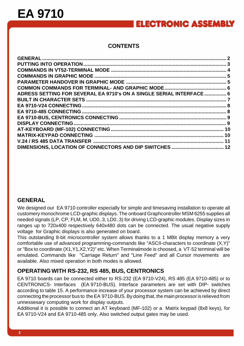
CONTENTS
GENERAL ...................................................................................................................................... 2PUTTING INTO OPERATION........................................................................................................ 3COMMANDS IN VT52-TERMINAL MODE .................................................................................... 4COMMANDS IN GRAPHIC MODE ................................................................................................ 5PARAMETER HANDOVER IN GRAPHIC MODE ......................................................................... 5COMMON COMMANDS FOR TERMINAL- AND GRAPHIC MODE............................................. 6ADRESS SETTING FOR SEVERAL EA 9710's ON A SINGLE SERIAL INTERFACE ................ 6BUILT IN CHARACTER SETS ...................................................................................................... 7EA 9710-V24 CONNECTING......................................................................................................... 8EA 9710-485 CONNECTING ......................................................................................................... 8EA 9710-BUS, CENTRONICS CONNECTING .............................................................................. 9DISPLAY CONNECTING............................................................................................................... 9AT-KEYBOARD (MF-102) CONNECTING .................................................................................. 10MATRIX-KEYPAD CONNECTING .............................................................................................. 10V.24 / RS 485 DATA TRANSFER ............................................................................................... 11DIMENSIONS, LOCATION OF CONNECTORS AND DIP SWITCHES ...................................... 12
GENERALWe designed our EA 9710 controller especially for simple and timesaving installation to operate allcustomery monochrome LCD-graphic displays. The onboard Graphcontroller MSM 6255 supplies allneeded signals (LP, CP, FLM, M, UD0..3, LD0..3) for driving LCD-graphic modules. Display sizes inranges up to 720x400 respectively 640x480 dots can be connected. The usual negative supplyvoltage for Graphic displays is also generated on board.This outstanding 8-bit microcontroller system allows thanks to a 1 MBit display memory a verycomfortable use of advanced programming-commands like "ASCII-characters to coordinate (X,Y)"or "Box to coordinate (X1,Y1,X2,Y2)" etc. When Terminalmode is choosed, a VT-52 terminal will beemulated. Commands like "Carriage Return" and "Line Feed" and all Cursor movements areavailable. Also mixed operation in both modes is allowed.
OPERATING WITH RS-232, RS 485, BUS, CENTRONICSEA 9710 boards can be connected either to RS-232 (EA 9710-V24), RS 485 (EA 9710-485) or toCENTRONICS- Interfaces (EA 9710-BUS). Interface parameters are set with DIP- switchesaccording to table 15. A performance increase of your processor system can be achieved by directconnecting the processor bus to the EA 9710-BUS. By doing that, the main processor is relieved fromunnessesary computing work for display outputs.Additional it is possible to connect an AT keyboard (MF-102) or a Matrix keypad (8x8 keys), forEA 9710-V24 and EA 9710-485 only. Also switched output gates may be used.
3
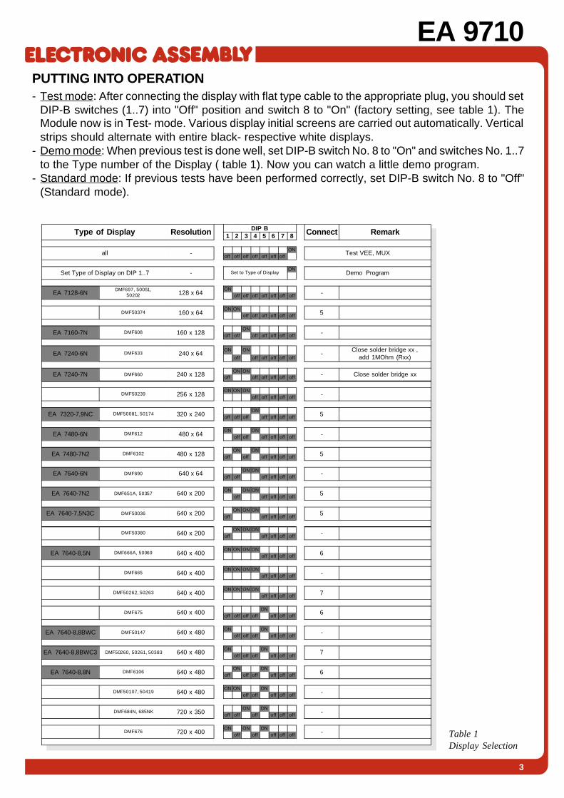
EA 9710PUTTING INTO OPERATION- Test mode: After connecting the display with flat type cable to the appropriate plug, you should set
DIP-B switches (1..7) into "Off" position and switch 8 to "On" (factory setting, see table 1). TheModule now is in Test- mode. Various display initial screens are carried out automatically. Verticalstrips should alternate with entire black- respective white displays.
- Demo mode: When previous test is done well, set DIP-B switch No. 8 to "On" and switches No. 1..7to the Type number of the Display ( table 1). Now you can watch a little demo program.
- Standard mode: If previous tests have been performed correctly, set DIP-B switch No. 8 to "Off"(Standard mode).
Type of Display Resolution DIP B Connect Remark1 2 3 4 5 6 7 8
all -ON
Test VEE, MUXoff off off off off off off
Set Type of Display on DIP 1..7 - Set to Type of DisplayON
Demo Program
EA 7128-6NDMF697, 50051,
50202 128 x 64ON
-off off off off off off off
DMF50374 160 x 64ON ON
5off off off off off off
EA 7160-7N DMF608 160 x 128ON
-off off off off off off off
EA 7240-6N DMF633 240 x 64ON ON
-Close solder bridge xx ,
add 1MOhm (Rxx)off off off off off off
EA 7240-7N DMF660 240 x 128ON ON
- Close solder bridge xxoff off off off off off
DMF50239 256 x 128ON ON ON
-off off off off off
EA 7320-7,9NC DMF50081, 50174 320 x 240ON
5off off off off off off off
EA 7480-6N DMF612 480 x 64ON ON
-off off off off off off
EA 7480-7N2 DMF6102 480 x 128ON ON
5off off off off off off
EA 7640-6N DMF690 640 x 64ON ON
-off off off off off off
EA 7640-7N2 DMF651A, 50357 640 x 200ON ON ON
5off off off off off
EA 7640-7,5N3C DMF50036 640 x 200ON ON ON
5off off off off off
DMF50380 640 x 200ON ON ON
-off off off off off
EA 7640-8,5N DMF666A, 50069 640 x 400ON ON ON ON
6off off off off
DMF665 640 x 400ON ON ON ON
-off off off off
DMF50262, 50263 640 x 400ON ON ON ON
7off off off off
DMF675 640 x 400ON
6off off off off off off off
EA 7640-8,8BWC DMF50147 640 x 480ON ON
-off off off off off off
EA 7640-8,8BWC3 DMF50260, 50261, 50383 640 x 480ON ON
7off off off off off off
EA 7640-8,8N DMF6106 640 x 480ON ON
6off off off off off off
DMF50107, 50419 640 x 480ON ON ON
-off off off off off
DMF684N, 685NK 720 x 350ON ON
-off off off off off off
DMF676 720 x 400ON ON ON
-off off off off off Table 1Display Selection

4
EA 9710COMMANDS IN TERMINAL MODEAfter power on the module is ready for receiving in terminal mode. All received characters are shownin ASCII format. Line carriage return is done automatically and, if display is filled, the page is scrollingto the top. The extended VT-52 terminal commands are listed in table 2.
Table 2: Commands in Terminal Mode
Terminal mode (extended VT-52)Command Codes DescriptionBackspace (decimal: 08) ^H Delete characters left of cursor, close up remaining line
Linefeed (decimal: 10) ^J Cursor to next line, position of columns remain
Formfeed (decimal: 12) ^L Clear display, cursor to left hand, top corner (position 1,1)
Carriage return (dec.: 13) ^M Cursor to left hand border
Cursor home ESC H Set cursor to left hand, top corner (position 1,1)
Cursor up ESC A Move cursor to next line above
Cursor down ESC B Move cursor to next line below
Cursor right ESC C Move cursor one character to the right
Cursor left ESC D Move cursor one character to the left
Cursor scroll to top ESC I Cursor to line above, scrolling top border, than cursor to the left
Save cursor position ESC j Save actual cursor position
Load cursor position ESC k Set cursor to saved position
Set cursor to position ESC Y s+32 z+32 Set cursor to absolute position column s and line z
Cursor on ESC e Cursor on (visible)
Cursor off ESC f Cursor off (invisible), conserves cursor type
Block cursor ESC 1 Cursor type: inverted block
Block cursor, flashing ESC 2 Cursor type: inverted block, flashing
Underline cursor ESC 3 Cursor type: underline
Underline cursor, flashing ESC 4 Cursor type: underline, flashing
Delete display image ESC E Clear screen, cursor to top lleft hand position 1,1)
Delete line ESC l Delete cursor pointed line
Delete line ESC M Delete cursor pointed line, remaining image scrolls up
Delete to the end of line ESC K Delete line from cursor position onward (incl.cursor position)
Delete to the end of page ESC J Delete total image beyond cursor position (incl. cursor position)
Delete line up to cursor ESC o Delete line up to cursor position
Delete image up to cursorposition
ESC d Delete image up to cursor position
Delete character ESC P Delete character at cursor position, move back remaining line
Insert blanks ESC @ Insert a blank at the place of cursor position
Insert new line ESC L Insert blank line in place of actual line; cursor moves to the left
Set to inverted letter ESC p Next images are shown inverted
Switch off inverted letters ESC q Next images are shown standard
Display inverted ESC r Inverse total display
Display standard ESC s Standard display
Autom. line overflow on ESC v Set cursor from right hand border automatic to the start of new line
Autom. line overflow off ESC w Cursor stays at right hand border

5
EA 9710COMMANDS IN GRAPHIC MODEKeying in: "ESC" "ESC" "G" changes to Graphic Mode. Letters x and y in table 3 are used for inputof coordinates, where the origin of coordinate (0,0) is situated in the left hand, top display corner.
Table 3: Commands in Graphic Mode
PARAMETER HANDOVER IN GRAPHIC MODE
Coordinates may be handed over in two ways:
- ASCII format: If commands are given in "CAPITAL LETTERS", the terminal expects valuesfor coordinates (x,y,n) in numerals 0..9, separated by comma. Each commandhas to be closed either with semikolon or with return.
i.E. set point at coordinate 258,10: P258,10;
- Binary format: If commands are given in "small letters", the terminal expects binary values.Coordinates (x,y) must be transmitted as 16 bit binary values (low-byte first,followed by high-byte). Other parameters (n) must be transmitted as 8 bitbinary values too, (insert no separating byte between coordinates andparameters). Commands don't need any closing byte.
i.E. set point at coordinate 258,10: $70 $02 $01 $0A $00
Graphic modeCommand Codes DescriptionClear display D L Delete display
Fill display D F Fill display
Invert display D I Invert display
Set graph mode V n1 n1: 1=set; 2=delete; 3=exor (dots, lines)
Line pattern F x Binary 16-bit form of line patterns
Set dot size Q n1 n2 Set dot size n1=widht, n2=hight in dots
Dot P x1 y1 Set dot to coordinates x1,y1
Straight line G x1 y1 x2 y2 Draw straight line with act. dot size/ line pattern
Straight line up to T x1 y1 Draw line from last stop to x1,y1
Rectangular K x1 y1 x2 y2 Draw rectangular with act. dot size / line pattern
Clear range L x1 y1 x2 y2 Delete a defined display area
Fill range E x1 y1 x2 y2 Fill a defined display ara
Invert range I x1 y1 x2 y2 Invert a defined display area
Copy range C x1 y1 x2 y2 x3 y3 Copya defined area to x3, y3 (multiples of 8 only)
Box B x1 y1 x2 y2 Draw blank box with border (actual dot size)
Box with shadow N x1 y1 x2 y2 n1 Box with border + shadow at x2,y2 ( n1=distance)
Set text mode M n1 n1: 1=set; 2=delete; 3=exor; 4=replace; 5=invert
ASCII- character A x1 y1 n1 Set sign n1 to pos. x1,y1 setzen
Character chain Z x1 y1 ... <cr> Display a character chain (...); Carrige return= end
Rescue image S n1 Copy visible image to buffer n1 (1 <= n1 <= max.)
Get image R n1 Copy image from buffer memory n1 into visible image
Divert graphic transfer J n1 Divert into image buffer n1 (0:= visible image)
Load range of image(upload)
U x1 y1 Datei Load a defined image area to x1,y1 (multiples of 8)
Save range of image(download)
O x1 y1 x2 y2 Save image range via V.24 resp. RS485 (multipl. of 8)

6
EA 9710COMMON COMMANDS FOR TERMINAL- AND GRAPHIC MODESeveral special commands are applicable in Graphic Mode as well as in Terminal Mode. Parameterhandover follows the same capital/small-letter rules as described under Graphic Mode.
ADRESSING SEVERAL EA 9710's ON A SINGLE INTERFACECommands "Select" and "Deselect" allow to adress and operate several terminals connected to asingle interface bus. The individual terminal adress is stored in EPROM (27C1000) at adress $00AD.EPROM value $FF (factory setting) can be reprogrammed any time to another value.
EA
971
0
EA
971
0
EA
971
0
Figure 1
Table 4: Common Commands for Terminal- and Graphic Mode
Common commands for terminal- and graphic modeCommand Codes DescriptionGraphic mode ESC ESC G Change to graphic-mode, image remains on display
Terminal mode ESC ESC T Change to terminal-mode, image remains on display
Select font ESC ESC F n1 n2n1:1-10 get font from Eprom n1:11-20 get upload Fontn2: 0: 0°; 1: 90°, 2: 180°, 3: 270°; rotation
Upload font ESC ESC U n1 Datei Load individual defined font Nr. n1=11-20
Font into upload area ESC ESC Y n1 Safe actual font as an upload font n1: 11-20
Increase contrast ESC ESC P Increase display voltage for one step
Decrease contrast ESC ESC M Decrease display voltage for one step
Contrast default ESC ESC Z Set display voltage to default
Auto transmit on ESC ESC E Enable auto transmit of keyboard strokes
Auto transmit off ESC ESC A Disable auto transmit of Keyboard strokes
Query matrix keypad ESC ESC B Query actual status of matrix keypad
Select ESC ESC S n1 Select EA 9710 by adress n1 (n1=255: all)
Deselect ESC ESC D n1 Deselect EA 9710 by adress n1 (n1=255: all)
Pause ESC ESC H n1 n1: 1..255 x 0,1 seconds pause

7
EA 9710BUILT IN CHARACTER SETSTerminal is delivered with 6 different character sets, already installed. Up to 10 more character setsmay be added by download.Because of the fact, that character sets does not always content all characters from 0 to 255, table5 shows the available characters. For instance the built in font No. 6, "BIG DIGITS", contents onlynumerals 0..9 and signs "-", "/", ".", ":".All characters are available in Text- and in Graphic Mode. Listed graphmode coordinates referencesto the left hand top corner of the character.
Table 5 Figure 2
Font Size in pixels ASCII- Range Description
1 8 x 8 0..255 Extended ASCII-code
2 8 x 16 0..255 Extended ASCII-code
3 16 x 16 0..255 Extended ASCII-code
4 16 x 32 32..127 ASCII-code
5 32 x 56 32..63 Numbers, punctuation, ...
6 32 x 56 64..95 Capital letters
7 32 x 56 96..127 Small letters
8 56 x 80 45..58 Big numbers
9 n/a
10 n/a
EXAMPLE FOR DISPLAY CONTROLTo demonstrate, how a complete display readout is "programmed" with a few commands, an exampleis printed below. Figure 3 shows the result of this demoprogram. Applied for that was a ¼-VGA displaywith 320x240 dots resolution.
Figure 3
ESC ESC F4,0 Font No. 4, Text onZ0,0,Temperatur Coordinate 0,0
N4,120,300,220,8 Box with gray shadowon Coordinate (120,300)
ESC ESC F8,0 Font No. 8, Text onZ40,130,25.4 Coordinate (40,130)
ESC ESC F4,1 Font No. 4, Text onZ8,198,Innen Coordinate (8,198)
ESC ESC F3,0 Font No. 3, Text onZ264,130,°C Coordinate (264,130)
G160,40,160,105 Line from (160,40) toG155,100,300,100 (160,105)...
G160,50,190,95 Line from (160,50) toT220,45 T300,70 (300,70)
F255 G160,80,230,70 Line Pattern No. 255, LineT250,30 T300,90 from (160,80) to (300,90)
Command Description Result (Display)
Table 6

8
EA 9710CONNECTING EA 9710-V24On board RS-232- drivers generate true RS-232 level withvoltage amplitudes of approx. ±10V. This guarantees safetransmissions up to 57600 Baud, even on long lines (upto15 meters). Communication parameters are set on DIP-switch A according to table 15 (see page 11)
Input Datas takes connector J2 on EA 9710-V24. Pinoutcan be seen in aside table. Connecting i.E.to a PC isparticulary simple with cable EA KV24-9, which isavailable as an option. Using this cable enables direct(1:1) plug in of EA 9710-V24 into serial PC- ports (i.E.COM1, 9-pin SUB-D connector).
If cable EA KV24-9 is not used, proceed according tofigure 4. In case, that wires for handshakes are not available,pins RTS and CTS must be bridged on EA 9710-V24 . In thisway EA 9710-V24 supports a special mode for softwarehandshakes XON / XOFF.
RS-232 connector J2Pin Symbol In/Out Funct ion
1 NC - n/c
2 DCD - Connected with pin 3 and pin 8
3 DSR - Connected with pin 2 and pin 8
4 TxD Out Transmit Data
5 CTS In Clear To Send
6 RxD In Receive Data
7 RTS Out Request To Send
8 DTR - Connected with pin 2 and pin 3
9 NC - n/c
10 G N D - Ground
HOST m. 9-pol. SUB-D
4
5
2
7
2
3
1
3
8
9
4
9
6
7
3
8
10 5 GND
Data Out - Data Out -
Data In - Data In -
HS Out - HS Out -
HS In - HS In -
Data Out + Data Out +
Data In + Data In +
HS Out + HS Out +
HS In + HS In +
GND
EA 9710-485
CONNECTING EA 9710-485On board RS422 / 485- drivers are generating differential voltageswith approx. ±5V amplitudes. This guarantees an extremely safetransmission up to 57.600 Baud, even on very long lines (up to 1.200meters). Communication parameters are set on DIP- switch Aaccording to table 15.Input Datas takes connector J2 on EA 9710-485. Pinout can be seenin aside table. Connecting i.E. to a PC is particulary simple with cableEA KV24-9, which is available as an option. Using this cable enablesdirect (1:1) plug in ofEA 9710-V24 into serialPC- ports (i.E. COM1,9-pin. SUB-Dconnector).
If cable EA KV24-9 is not used, proceed according tofigure 5. In case, that wires for handshakes are notavailable, pins RTS and CTS must be bridged onEA 9710-485. In this case, EA 9710-485 supports aspecial mode for software handshakes XON / XOFF.
RS422 / RS485 connector J2Pin Symbol Funct ion
1 NC n/c
2 Data In - Receive Data
3 Data In + Receive Data
4 Data Out - Transmit Data
5 Data Out + Transmit Data
6 HS In - Handshake
7 HS In + Handshake
8 HS Out - Handshake
9 HS Out + Handshake
10 G N D 0V, Ground
Figure 4
Figure 5
HOST m. 9-pol. SUB-D
2
8
3
1
6
4
4 2
6 3
7 8
5 7
10 5
DCD
TXD
DTR
DSR
RXD
RTS
CTS
GND
DCD
DTR
DSR
TXD
RXD
RTS
CTS
GND
EA 9710-V24

9
EA 9710
Centronics bus connector J3Pin Symbol Level Function Pin Symbol Level Function
1 Strobe L Data transfer 2 NC - n/c
3 Data 0 H / L Bit 0 LSB 4 VDD H + 5V
5 Data 1 H / L Bit 1 6 NC - n/c
7 Data 2 H / L Bit 2 8 NC - n/c
9 Data 3 H / L Bit 3 10 GND L 0V Ground
11 Data 4 H / L Bit 4 12 GND L 0V Ground
13 Data 5 H / L Bit 5 14 GND L 0V Ground
15 Data 6 H / L Bit 6 16 GND L 0V Ground
17 Data 7 H / L Bit 7 MSB 18 GND L 0V Ground
19 Ack L Acknowledge 20 GND L 0V Ground
21 Busy H In progress 22 GND L 0V Ground
23 GND L 0V Ground 24 GND L 0V Ground
25 VDD H + 5V 26 NC - n/c
CONNECTING EA 9710-BUS, CENTRONICSConnector J3 is assigned forconnection to Centronicsinterface. A 25-pin Centronicsconnector (male) can becrimped direct onto a flat typecable, and allows in thiscombination i.E. directoperation with PC.It´s also possible to operatethe terminal directly viaCentronics interface on aprocessor system bus.Hereby the input "Strobe"takes over the function of alow active "Enable". Datatakeover happens at the L-Hedge. On fast processorsystems should be waited until pin "Busy" is on low level, before transfer new datas.
Table 9
Display connector J6Pin Symbol Level Function
1 FLM H/L Frame Signal
2 LP H/L Data Latch Signal
3 CP H/L Data Shift Clock
4 M H/L Alternate Signal
5 VADJ - Contrast adjustment
6 VDD H Positive supply forelectronic
7 VSS L Negative supply forelectronic
8 VEE - Display voltage
9 DU0 H/L Display Data 0 (Upper)
10 DU1 H/L Display Data 1 (Upper)
11 DU2 H/L Display Data 2 (Upper)
12 DU3 H/L Display Data 3 (Upper)
13 DL0 H/L Display Data 0 (Lower)
14 DL1 H/L Display Data 1 (Lower)
15 DL2 H/L Display Data 2 (Lower)
16 DL3 H/L Display Data 3 (Lower)
Display connector J7 and J7-2Pin Symbol Level Function
1 FLM H/L Frame Signal
2 LP H/L Data Latch Signal
3 CP H/L Data Shift Clock
4 DOFF H H: Display on (L:OFF)
5 VDD H Positive supply forelectronic
6 VSS L Negative supply forelectronic
7 VEE - Display voltage
8 DU0 H/L Display Data 0 (Upper)
9 DU1 H/L Display Data 1 (Upper)
10 DU2 H/L Display Data 2 (Upper)
11 DU3 H/L Display Data 3 (Upper)
12 DL0 H/L Display Data 0 (Lower)
13 DL1 H/L Display Data 1 (Lower)
14 DL2 H/L Display Data 2 (Lower)
15 DL3 H/L Display Data 3 (Lower)
Display connector J5Pin Symbol Level Function
1 FLM H/L Frame Signal
2 LP H/L Data Latch Signal
3 CP H/L Data Shift Clock
4 M H/L Alternate Signal
5 VADJ - Contrast adjustment
6 VDD H Positive supply forelectronic
7 VSS LNegative supply forelectronic
8 VEE - Display voltage
9 D0 H/L Display Data 0
10 D1 H/L Display Data 1
11 D2 H/L Display Data 2
12 D3 H/L Display Data 3
Table 10
Table 11Table 12
DISPLAY CONNECTIONOn board are four rows solder terminals for direct connection (1:1 link) to most customary LCD-Graphic Modules.

10
EA 9710
CONNECTING (MATRIX-) KEYPADConnector J4 allows connection to single keys orto Matrix- keypads with up to 8x8 keys. Thecontact bouncing is eliminated by software.Please take into consideration, that this keypadfunctions are supported by version RS-232 andversion RS 485 only.Keys are connected to input- and output gates,where each input gate is shunted by a 100kΩpullup resistor. Up to 8 keys may be connected toa single output gate.In order to recognize fast double keystrokes, theoutput gates have to be decoupled. Best way toachieve that is using Schottky- Diodes (i.E.BAT 43).On multiple keystrokes (>2) each individual keymust be decoupled by separate diode.
An AT-keyboard can be connected to connectorJ3. Please be aware, that keyboard functionsare supported by versions RS-232 and RS 485only.Received MF-102 keyboard datas are bufferedin terminal memory and will be transfered viaRS-232/RS485 interface. The output starts onlyafter command "Auto Transmit On" is given.When operating several terminals on one line,its advisable to give immediate after data
receiving the command "Automatisch senden aus" to prevent datacrasheswhen single terminals are transmitting arbitrary. No conversion (i.E.) to ASCII-characters takes place, therefore various on market available keyboards can
b e used. An identification string, like it's usual on matrix- keypads, won't be issued.
MF-102 Keyboard connector J3Pin Symbol Function Pin Symbol Function
1 CLK Clock line 2 - n/a
3 DATA Data line 4 VDD + 5V
5 - n/a 6 - n/a
7 - n/a 8 - n/a
9 - n/a 10 GND 0V Ground
CONNECTING AT-KEYBOARD (MF-102)
Matrix - Keypad connector J4Pin Symbol Function Pin Symbol Function
1 GND 0V Ground 2 VDD + 5V
3 OUT 1 output line 1 4 OUT 2 output line 2
5 OUT 3 output line 3 6 OUT 4 output line 4
7 OUT 5 output line 5 8 OUT 6 output line 6
9 OUT 7 output line 6 10 OUT 8 output line 8
11 IN 1 input column 1 12 IN 2 input column 2
13 IN 3 input column 3 14 IN 4 input column 4
15 IN 5 input column 5 16 IN 6 input column 6
17 IN 7 input column 7 18 IN 8 input column 8
19 GND 0V Ground 20 VDD + 5V
Transmitting keystrokesAfter the terminal is swichted on, all keystrokes willbe stored. For automatic transmitting of eachchange on input gates, the command "automatictransmission on" (ESC ESC E) must be given. It'salso possible, to query the actual status ofkeystrokes by commands: ESC ESC B. This makessense, especially when several terminals operateon one line, it prevents a datacrash when singleterminals are transmitting arbitrary.
1 2
9 10
J3
Socket for MF-II Keyboard(Solder side)
1345
2
Figure 7
1 2
19 20
J4
Out 1
In 1
In 2
In 3
In 4
Out 3Out 4
Out 2
1 2
19 20
J4
Out 1
In 1
In 2
In 3
In 4
In 5
In 6
In 7
In 8
IdentificationsIn order to distinguish transmitted datas (Matrix, MF-102) from each other, an ASCII-character ´m´ will be sent first viathe RS-232/RS485 interface to identify the Matrix keypad. Than, the keystroke numbers follow in binary format, finallyfollowed by a closing byte (binary: 0). On each change, pressing and releasing a key, all key strokes will be stilltransmitted. The number of an individual key can be evaluated:Number of key = (output -1) * 8 + input , output and input must be a number between 1 and 8.
Figure 6
11
EA 9710
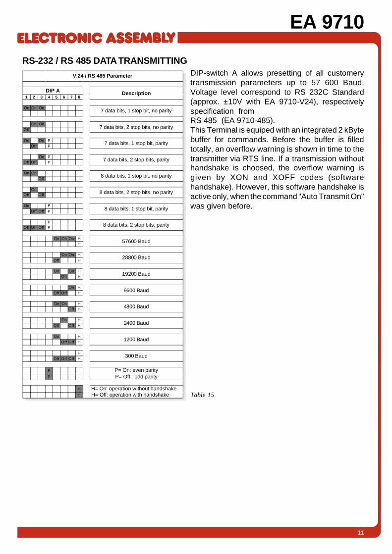
RS-232 / RS 485 DATA TRANSMITTINGDIP-switch A allows presetting of all customerytransmission parameters up to 57 600 Baud.Voltage level correspond to RS 232C Standard(approx. ±10V with EA 9710-V24), respectivelyspecification fromRS 485 (EA 9710-485).This Terminal is equiped with an integrated 2 kBytebuffer for commands. Before the buffer is filledtotally, an overflow warning is shown in time to thetransmitter via RTS line. If a transmission withouthandshake is choosed, the overflow warning isgiven by XON and XOFF codes (softwarehandshake). However, this software handshake isactive only, when the command "Auto Transmit On"was given before.
V.24 / RS 485 Parameter
DIP A Description1 2 3 4 5 6 7 8
On On On7 data bits, 1 stop bit, no parity
On On7 data bits, 2 stop bits, no parityOff
On On P7 data bits, 1 stop bit, parity
Off P
On P7 data bits, 2 stop bits, parityOff Off P
On On8 data bits, 1 stop bit, no parity
Off
On8 data bits, 2 stop bits, no parityOff Off
On P8 data bits, 1 stop bit, parityOff Off P
P8 data bits, 2 stop bits, parityOff Off Off P
On On On H57600 BaudH
On On H28800 Baud
Off H
On On H19200 BaudOff H
On H9600 BaudOff Off H
On On H4800 BaudOff H
On H2400 BaudOff Off H
On H1200 BaudOff Off H
H300 Baud
Off Off Off H
P P= On: even parityP= Off: odd parityP
H H= On: operation without handshake H= Off: operation with handshakeH Table 15
EA 9710
LOCHHAMER SCHLAG 17 · D-82166 GRÄFELFINGPhone +49-89-8541991 · FAX +49-89-8541721 · lcd-module.de
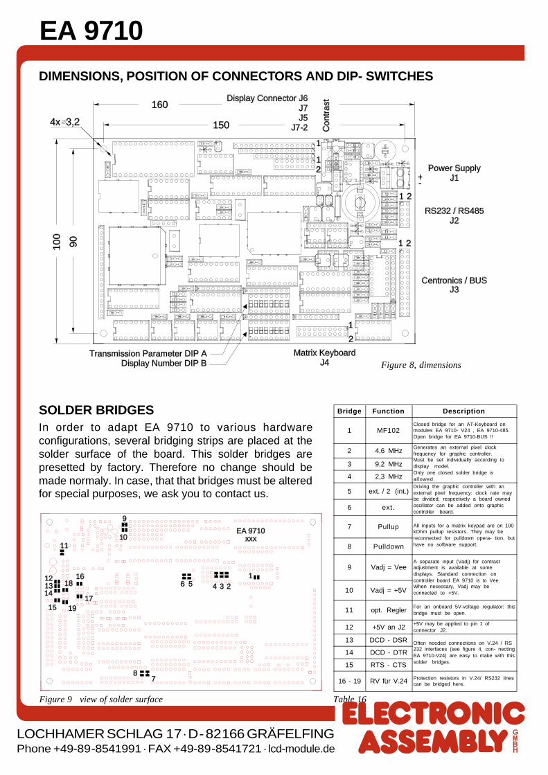
DIMENSIONS, POSITION OF CONNECTORS AND DIP- SWITCHES
Power SupplyJ1
RS232 / RS485J2
Centronics / BUSJ3
160
4x 3,2 150
90100
Matrix KeyboardJ4
Transmission Parameter DIP ADisplay Number DIP B
Display Connector J6J7J5
J7-2 Con
tras
t
1
1
1
1
12
2
+-
2
2
Figure 8, dimensions
Table 16Figure 9 view of solder surface
EA 9710xxx
9
1011
1314
15
12 16
17
18
19
87
6 5 4 3 21
Bridge Function Description
1 MF102Closed bridge for an AT-Keyboard onmodules EA 9710- V24 , EA 9710-485.Open bridge for EA 9710-BUS !!
2 4,6 MHzGenerates an external pixel clockfrequency for graphic controller.Must be set individually according todisplay model.Only one closed solder bridge isallowed.
3 9,2 MHz
4 2,3 MHz
5 ext. / 2 (int.)Driving the graphic controller with anexternal pixel frequency: clock rate maybe divided, respectively a board ownedoscillator can be added onto graphiccontroller board.
6 ext.
7 Pullup All inputs for a matrix keypad are on 100kOhm pullup resistors. They may bereconnected for pulldown opera- tion, buthave no software support.8 Pulldown
9 Vadj = VeeA separate input (Vadj) for contrastadjustment is available at somedisplays. Standard connection oncontroller board EA 9710 is to Vee.When necessary, Vadj may beconnected to +5V.10 Vadj = +5V
11 opt. ReglerFor an onboard 5V-voltage regulator: thisbridge must be open.
12 +5V an J2+5V may be applied to pin 1 ofconnector J2.
13 DCD - DSR Often needed connections on V.24 / RS232 interfaces (see figure 4, con- nectingEA 9710-V24) are easy to make with thissolder bridges.
14 DCD - DTR
15 RTS - CTS
16 - 19 RV für V.24 Protection resistors in V.24/ RS232 linescan be bridged here.
SOLDER BRIDGESIn order to adapt EA 9710 to various hardwareconfigurations, several bridging strips are placed at thesolder surface of the board. This solder bridges arepresetted by factory. Therefore no change should bemade normaly. In case, that that bridges must be alteredfor special purposes, we ask you to contact us.