Embed Size (px)
Citation preview

1
Landslide Types & Processes
By :
IR. DR. MOHD ASBI BIN OTHMAN
Mohd Asbi & Associates
Course contents
• What is landslide?
• Parts of landslide (common nomenclature)
d l d l f d d f• Landslide classification and identification
• Common landslide types
• Causes of landslide
• Landslides outside Malaysia
• Case studies
2
What is landslide ?
The term "landslide" describes a wide variety of processesThe term landslide describes a wide variety of processes that result in the downward and outward movement of slope-forming materials including rock, soil, artificial fill, or a combination of these.
(USGS, Fact Sheet 2004–3072 )
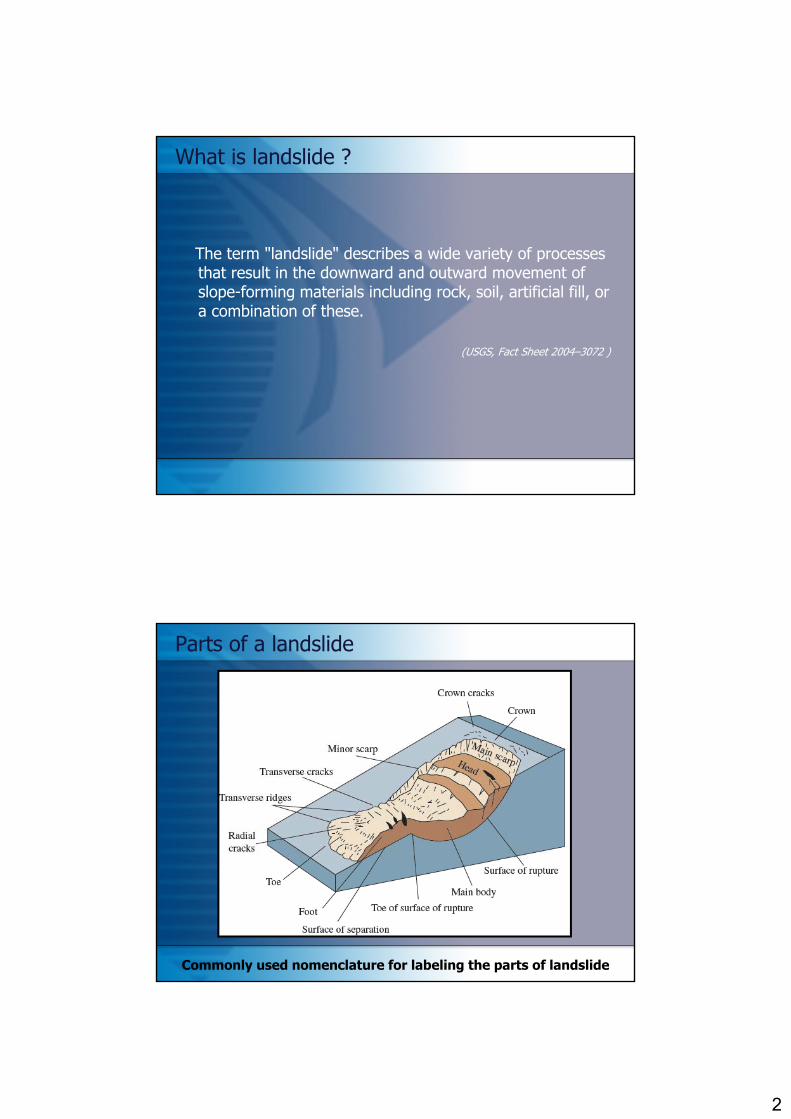
Parts of a landslide
Commonly used nomenclature for labeling the parts of landslide

3
Landslide classification and identification
• Landslides or slope movements can be classified in many ways. There are many attributes used as criteria for identification and classification including:
- Rate of movement: This ranges from very slow creep (mm/yr) to extremely rapid (m/sec).
-Type of material: Landslides are composed of bedrock, unconsolidated sediment and/or organic debris.
- Nature of movement:The materials may move by falling, toppling, sliding, spreading, or flowing.
Common landslide types - rotational landslide
This is a slide in which the surface of rupture is curved concavely upward and the slide movement is roughly rotational about an axis that is parallel to the ground surface and transverse across the slide

4
Common landslide types - translational landslide
In this type of slide, the landslide mass moves along a roughly planar surface with little rotation or backward tilting
Common landslide types - block landslide
A block slide is a translational slide in which the moving mass consists of a single unit or a few closely related units that move downslope as a relatively coherent mass

5
Common landslide types - rockfall
Falls are abrupt movements of masses of geologic materials, such as rocks and boulders, that become detached from steep l liffslopes or cliffs .
Separation occurs along discontinuities such as fractures, joints, and bedding planes, and movement occurs by free-fall, bouncing, and rolling.
Falls are strongly influenced by gravity, mechanical weathering, and the presence of interstitial water.
Common landslide types - topple
Toppling failures are distinguished by the forward rotation of a unit or units about some pivotal point, below or low in the unit, under the actions of gravity and forces exerted by adjacent units or by fluids in cracks
6
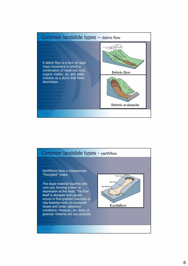
Common landslide types – debris flow
A debris flow is a form of rapid mass movement in which a combination of loose soil, rock, organic matter, air, and water mobilize as a slurry that flows downslope.
Common landslide types - earthflow
Earthflows have a characteristic "hourglass" shape .
The slope material liquefies and runs out, forming a bowl or depression at the head. The flow itself is elongate and usually occurs in fine-grained materials or clay-bearing rocks on moderate slopes and under saturated conditions. However, dry flows of granular material are also possible

7
Common landslide types - creep
Creep is the imperceptibly slow, steady, downward movement of slope-forming soil or rock. There are generally three types of creep: are generally three types of creep:
• Seasonal, where movement is within the depth of soil affected by seasonal changes in soil moisture and soil temperature • Continuous, where shear stress continuously exceeds the strength of the materialof the material • Progressive, where slopes are reaching the point of failure as other types of mass movements.
Common landslide types – lateral spread
Lateral spreads are distinctive because they usually occur on very gentle slopes or flat terrain. The dominant mode of movement is lateral extension accompanied by shear or tensile fractures.

8
Causes of Landslides
There are three major factors that can cause the landslide:There are three major factors that can cause the landslide:
• Hydrogeological factor• Morphological factor• Human factor

9
Causes of Landslides
Hydrogeological causes
• Weak or sensitive materialsW th d t i l• Weathered materials
• Sheared, jointed, or fissured materials• Adversely oriented discontinuity (bedding, schistosity, fault,
unconformity, contact, and so forth)• Contrast in permeability and/or stiffness of materials• INTENSE AND PROLONGED RAINFALL
Causes of Landslides
Morphological causes
• Tectonic or volcanic upliftGl i l b d• Glacial rebound
• Fluvial, wave, or glacial erosion of slope toe or lateral margins• Subterranean erosion (solution, piping)• Deposition loading slope or its crest• Vegetation removal (by fire, drought)• Thawing• Freeze-and-thaw weathering• Freeze and thaw weathering• Shrink-and-swell weathering

10
Causes of Landslides
Human causes
• Excavation of slope or its toeL di f l it t• Loading of slope or its crest
• Drawdown (of reservoirs)• Deforestation• Irrigation• Mining• Artificial vibration• Water leakage from utilities• Water leakage from utilities
Brand E.W., (1981) pointed out that:
“The majority of failures in the residual soil cut slopes are due to the rainfall”

11
Hencher, S. et. al. (1984) cited that:
“In predicting the stability of Hong Kong slopes, the groundwater conditions are
poorly understood”
Prof. Dr Steve HencherHong Kong University
Landslides Outside Malaysia
12
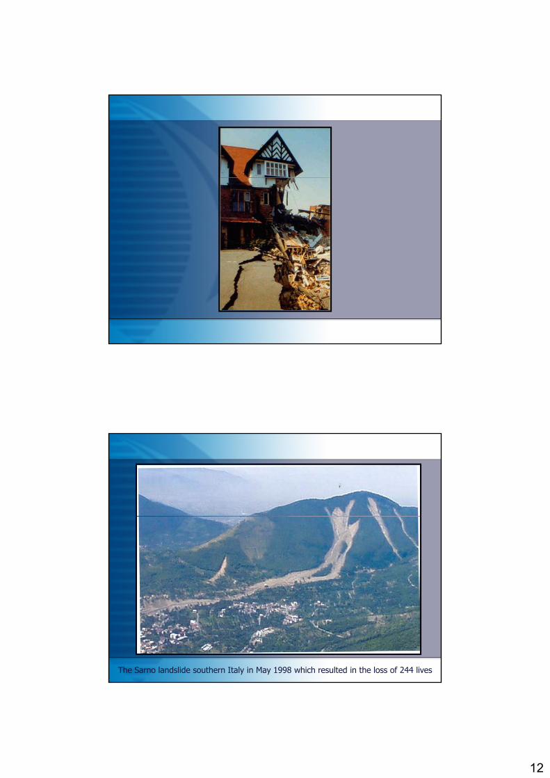
The Sarno landslide southern Italy in May 1998 which resulted in the loss of 244 lives

13
before
after
The Vajont landslide in Italy, caused by the collapse of a valley-side into a reservoir.
One of the most famous examples of a toppling failure occurred on the 26 July 1928 at Niton Underclift, Isle of Wight

14
A massive rock fall in the Commune of Sennoz, France with debris impacting close to residential development
Rock fall at Ancona, Adriatic coast of Italy

15
The landslide extends for 2.5km through the southern slopes of Mount Teverone and the major mudslide was activated after intense rainfall in October 1960.
Coastal landsliding at Overstrand, Norfolk , UK – part of this frontage has now been protected.

16
CASE STUDIES
CASE STUDY 1BUKIT LANJAN ROCK SLOPE FAILURE
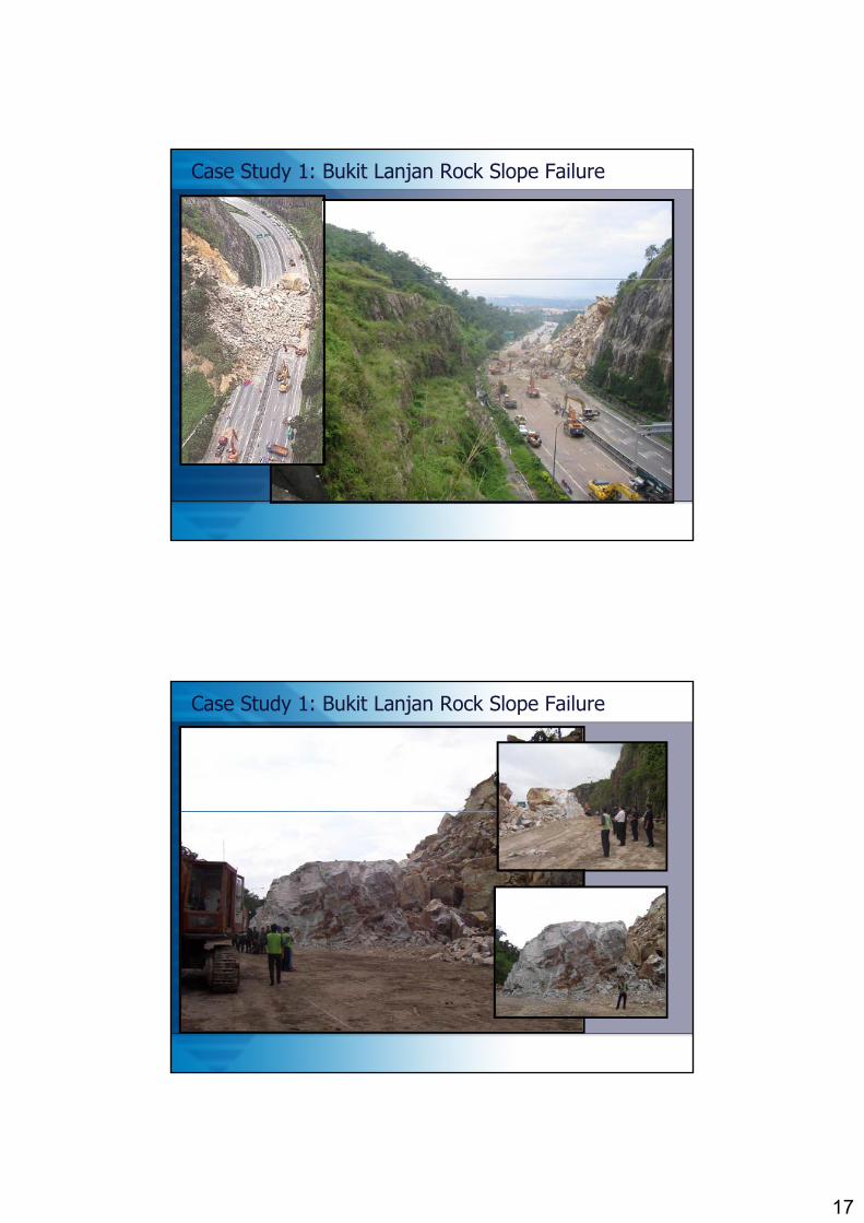
Case Study 1: Bukit Lanjan Rock Slope Failure
• On the 26 November 2003 at about 07:16 a very large rock slope failure occurred at kilometer 21.8 of the Bukit Lanjan Interchange on the New Klang Valley Expressway (NKVE).
• The rock slope failure involved an estimated 35,000 m3 of rock debris, mainly angular blocks of various sizes, which came to rest on the expressway. The failure materials blocked the entire expressway forcing the closure of the road to the public
17
Case Study 1: Bukit Lanjan Rock Slope Failure
Case Study 1: Bukit Lanjan Rock Slope Failure
18
Case Study 1: Bukit Lanjan Rock Slope Failure
Analysis of Failure
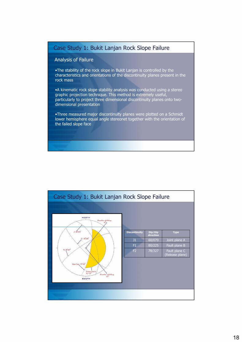
•The stability of the rock slope in Bukit Lanjan is controlled by the characteristics and orientations of the discontinuity planes present in the rock mass
•A kinematic rock slope stability analysis was conducted using a stereo graphic projection technique. This method is extremely useful, particularly to project three dimensional discontinuity planes onto two-dimensional presentation
•Three measured major discontinuity planes were plotted on a Schmidt•Three measured major discontinuity planes were plotted on a Schmidt lower hemisphere equal angle stereonet together with the orientation of the failed slope face
Case Study 1: Bukit Lanjan Rock Slope Failure
Discontinuity Dip/Dip direction
Type
J1 60/070 Joint plane A
F1 80/225 Fault plane B
F2 78/327 Fault plane C (Release plane)

19
Case Study 1: Bukit Lanjan Rock Slope Failure
• The rock slope failure at Bukit Lanjan was due to a huge wedge block which was formed along the intersection between a steeply dipping fault plane F1 (dip/dip direction: 80°/225°), and a more gently dipping major joint plane J1 (dip/dip direction: 60%70°) with a faultdipping major joint plane J1 (dip/dip direction: 60%70 ), with a fault plane F2 (dip/dip direction: 78°/327°) as a release plane.
• The line of intersection plunged at an angle of 33° with the direction of sliding toward 140°.
• The development of groundwater pressure within this release plane ld h d d h i i f b l icould have reduced the resisting force, subsequently promoting
failure.
Case Study 1: Bukit Lanjan Rock Slope Failure
• Since the analysis indicated that unfavorable discontinuity orientations and built-up water pressure along these discontinuities were two most importance causal factors, one might still ask why did the failure occur several years after the construction of the slope.
• A more straight forward answer to this question is related to the unusual condition for the triggering factor.
• Rainfall analysis based on the data collected by the Malaysian Meteorological Service at Petaling Jaya and Old Subang Airport indicated that rainfall in November 2003 for both stations was extremely high. In fact, the monthly rainfall of 472mm at the Old Subang Airport station was the highest monthly rainfall since 1966.

20
Case Study 1: Bukit Lanjan Rock Slope Failure
• The rehabilitation scheme chosen was rock slope re-profiling because the construction was quick, simple and most cost compared to other options
Rehabilitation Scheme
options.
• An overall rock slope profile of 48° was considered appropriate for the anticipated in situ instability condition
Case Study 1: Bukit Lanjan Rock Slope Failure
• Slope re-profiling usually reduces the possibility of large scale wedge and/or planar type failure.
• To contain localized minor rock and debris falls, the design would , ghave to incorporate appropriately designed catch berms, rock bolts, rockfill buttress, protection screens, rock trap ditches and fencing.
• Localized stabilization measures such as rock bolts, rock anchors, dowels, shotcrete and concrete buttress were also anticipated to support kinematically unstable blocks that would become exposed during the construction works.
• Drainage works were also incorporated in the form of surface and horizontal drains; the latter were designed in excess of 20 metres to 30 meters in depth

21
Case Study 1: Bukit Lanjan Rock Slope Failure
Trajectory analysis – Cross section
Case Study 1: Bukit Lanjan Rock Slope Failure
Trajectory analysis – Rock fall travel distance & bounce height

22
Case Study 1: Bukit Lanjan Rock Slope Failure
CASE STUDIES
CASE STUDY 2EMBANKMENT FAILURE AT ULU YAM ROAD

23
Case Study 2: Embankment Failure at Ulu Yam Road
• A major landslide occurred at KM 12, Jalan Ulu Gombak - Ulu Yam Baru (B23) located in Daerah Gombak on 22 Nov 2002.
• The landslide was triggered by intense and prolonged rainfall brought down tonnes of earth and damaged almost three-quarters of the width of the road. No fatalities were reported in the incident.
• The rotational landslide measured approximately 70m wide and 10m high. The crown and surface of rupture were circular.
• The toe of the slope was seen to have heaved indicating a very high• The toe of the slope was seen to have heaved indicating a very high pore water pressure build up prior to the failure.
• This is common for areas where large catchment is found upslope.
Case Study 2: Embankment Failure at Ulu Yam Road

24
Case Study 2: Embankment Failure at Ulu Yam Road
Case Study 2: Embankment Failure at Ulu Yam Road
• In order not to sacrifice the geometric standard of the section (vertical and horizontal alignment), it was proposed that the original
Rehabilitation Scheme
alignment was maintained.
• This required a reconstruction of the embankment. Given the limited Right of Way (forest reserved), it was proposed that a geogrid reinforced wall (approximately 5m in height) was designed to act as a gravity structure to the embankment.

25
Case Study 2: Embankment Failure at Ulu Yam Road
CASE STUDIES
CASE STUDY 3DEBRIS FLOW AT THE TUNNEL BYPASS
ROAD, GENTING SEMPAH
26
Case Study 3: Debris flow at the tunnel bypass Road, Genting Sempah
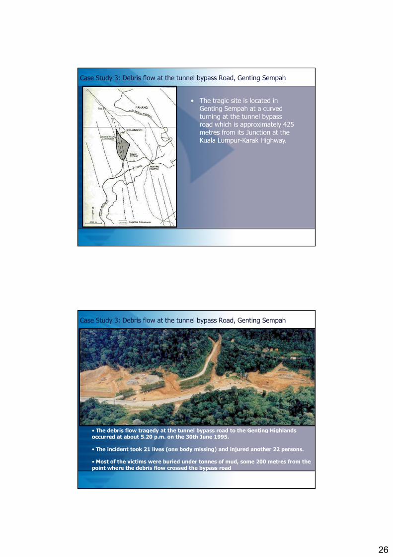
• The tragic site is located in Genting Sempah at a curved turning at the tunnel bypass road which is approximately 425 pp ymetres from its Junction at the Kuala Lumpur-Karak Highway.
Case Study 3: Debris flow at the tunnel bypass Road, Genting Sempah
Th d b i fl t d t th t l b d t th G ti Hi hl d• The debris flow tragedy at the tunnel bypass road to the Genting Highlands occurred at about 5.20 p.m. on the 30th June 1995.
• The incident took 21 lives (one body missing) and injured another 22 persons.
• Most of the victims were buried under tonnes of mud, some 200 metres from the point where the debris flow crossed the bypass road

27
Case Study 3: Debris flow at the tunnel bypass Road, Genting Sempah
Case Study 3: Debris flow at the tunnel bypass Road, Genting Sempah
• A very intense and heavy rainfall occurred over the Genting Sempah area covering the debris flow catchment from about 3.40 p.m. to about 5.30 p.m. on the 30th June 1995.
• As a consequence, flash floods were reported at the highway tunnel and the surrounding Genting Sempah area resulting in a massive traffic jam in the area.
• The debris flow, consisting essentially of large volume of water carrying mud, stone, cobbles, boulders and tree trunks flowed down a stream course at great velocity and force sweeping across the tunnel bypass road at the curved turning where heavy traffic was lined up.

28
Case Study 3: Debris flow at the tunnel bypass Road, Genting Sempah
Case Study 3: Debris flow at the tunnel bypass Road, Genting Sempah
The aftermath at the main stream

29
Case Study 3: Debris flow at the tunnel bypass Road, Genting Sempah
• The debris flow was initiated by the impounding of the main stream within a valley followed by subsequent breaching which resulted in massive flow sweeping across the tunnel bypass road with great force and velocityand velocity.
• The impounding was caused by a debris avalanche involving some 5100 cubic metres of earth, measuring 120 metres and 75 metres in length and height respectively from the main stream.
Case Study 3: Debris flow at the tunnel bypass Road, Genting Sempah
Debris avalanche responsible for the impounding

30
Case Study 3: Debris flow at the tunnel bypass Road, Genting Sempah
Evidence of impounding was clearly seen as mud stains on the bark of trees along the main stream.
Case Study 3: Debris flow at the tunnel bypass Road, Genting Sempah
The 3-kilometer radius from the debris flow site where other debris flow and other forms of instability were recorded

31
Case Study 3: Debris flow at the tunnel bypass Road, Genting Sempah
• Rainfall analysis was undertaken based on the rainfall records of Department of Irrigation and Drainage's (DID) Genting Sempah rainfall recording station No. 3317004 located at about 3 km north of the tragic sitethe tragic site.
• The frequency analysis of annual maximum 2-hour rainfall records indicated that the 30th June 1995 storm with a total rainfall of 96.5 mm had a probability of recurrence of about 16 years.
Case Study 3: Debris flow at the tunnel bypass Road, Genting Sempah
• Characterization of the storm using a total of 10 rainfall stations around the Genting Sempah area showed that the debris flow catchment was located within the centre or core of the storm.

32
Case Study 3: Debris flow at the tunnel bypass Road, Genting Sempah
• The month of June 1995 was abnormally wet over the Genting Sempah area.
• A total rainfall of 428.5 mm recorded for the month of June 1995 was the highest in 20 years, approximately 2.6 times the long-term average rainfall of 163.2 mm.
• The 6-day accumulated rainfall ending on 30th June 1995 was recorded at 2075 mm, constituting approximately 50% of the monthly total and exceeding the June long term average of 163.2 mm by 27%.
• Such high antecedent rainfall which occurred within the debris flow catchment was responsible for extreme wetting of the soil prior to the 30th June storm.
Case Study 3: Debris flow at the tunnel bypass Road, Genting Sempah
• The flood discharge hydro graph for the debris flow catchment indicated that storm flow would have started at 4.00 p.m. and reached its peak between 5.00 pm. and 5.15 p.m. where the discharge rate was greater than 2.5 cubic metres per second which
t l t 1000 ti th t f th l flwas at least 1000 times that of the normal flow.
• The total volume produced by the 2-hour storm at the debris flow catchment was estimated to be about 10,600 cubic metres.

33
CASE STUDIES
CASE STUDY 4LANDSLIDE AT POS SELIM-CAMERON
HIGHLAND HIGHWAY
Case Study 4: Landslide at Pos Selim-Cameron Highland Highway
• The Pos Selim-Cameron Highland is one (package 2) of the 8 packages of road that link Simpang Pulai in Perak & Kuala Berang in T th 3 d E W Hi h i P i l M l i ft thTerengganu; the 3rd E-W Highway in Peninsular Malaysia, after the KL-Karak & Gerik-Jeli Highway.
• The construction of the 35 km highway was started in 1997 and was scheduled to be completed on Apr 2000, but having confronted with slope failures, the opening of the highway to the public had been delayed to 2004.
• One of the major failures was the deep-seated, structurally-controlled massive cut slope failure between CH23000 – CH24500.

34
Case Study 4: Landslide at Pos Selim-Cameron Highland Highway
August 2000
After completion of a few berms, the slope started to fail. A series of failures on this slope was first reported in April 2000 after a long period of intense and heavy rainfall which triggered further retrogressive slips in the
upper catchment .
Case Study 4: Landslide at Pos Selim-Cameron Highland Highway
October 2001

35
Case Study 4: Landslide at Pos Selim-Cameron Highland Highway
2002
The deep-seated failure mode exhibited by these failures had prohibited the adoption of stabilization measures using active anchors, passive soil nails, sprayed concrete etc. Eventually, the Main Contractor had no alternative
but to adopt the rehabilitation scheme involving slope re-profiling.
Case Study 4: Landslide at Pos Selim-Cameron Highland Highway
August 2003
Despite the efforts by the Main Contractor to stabilize the slope by re-profiling , the high cut slope at between CH23000-CH24560 is still experiencing deep-seated slope movement
36
Case Study 3: Landslide at Pos Selim-Cameron Highland Highway
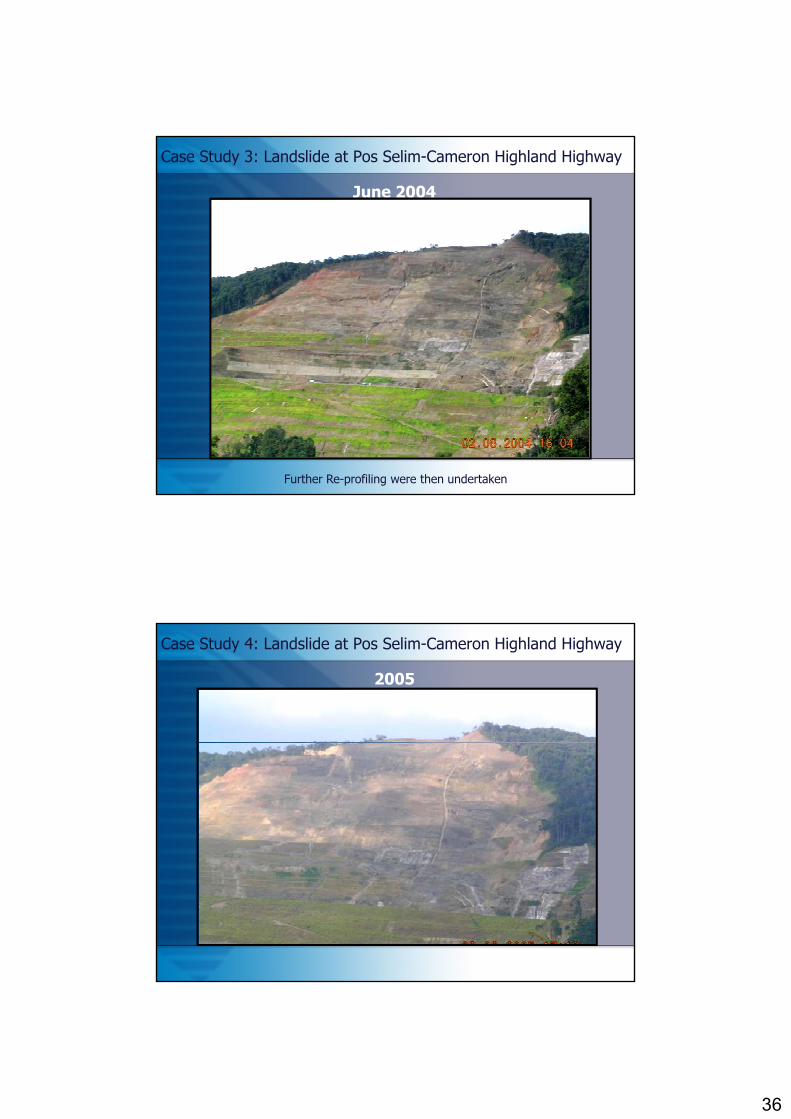
June 2004
Further Re-profiling were then undertaken
Case Study 4: Landslide at Pos Selim-Cameron Highland Highway
2005

37
Case Study 4: Landslide at Pos Selim-Cameron Highland Highway
Field-sketch to show the approximate extend of the moving blocks within the major failure
Case Study 4: Landslide at Pos Selim-Cameron Highland Highway
Interpretative cross section of the slope based on the kinematic stability analysis and field data, showing the likely structural orientation and mechanism of the slope failure in the form of a “passive wedge”.

38
CH 23+900 – CH24+400 (The major failure)
CROSS SECTION SHOWING THE LIKELY MECHANISME OF THE MAJOR FAILURE BETWEEN CH 23900 – CH 24400
1

39
CH 23+900 – CH24+400 (The major failure)
CROSS SECTION SHOWING THE LIKELY MECHANISME OF THE MAJOR FAILURE BETWEEN CH 23900 – CH 24400
2
40
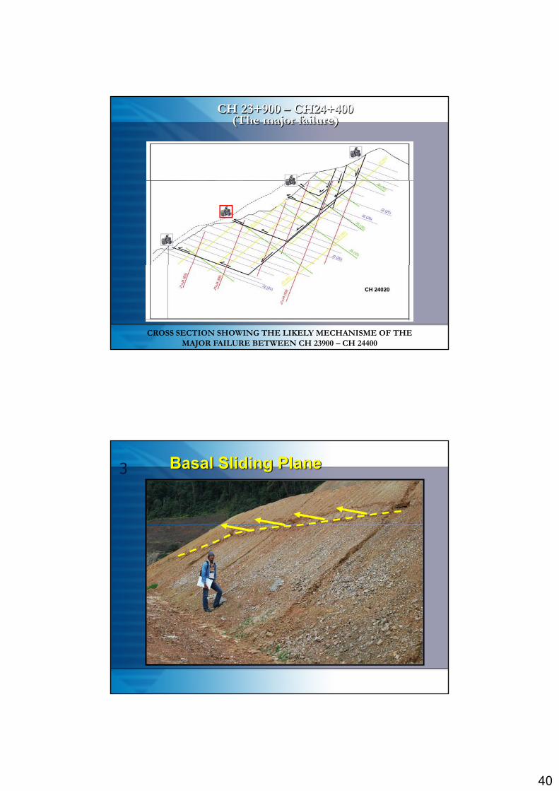
CH 23+900 – CH24+400 (The major failure)
CROSS SECTION SHOWING THE LIKELY MECHANISME OF THE MAJOR FAILURE BETWEEN CH 23900 – CH 24400
3 Basal Sliding Plane
41
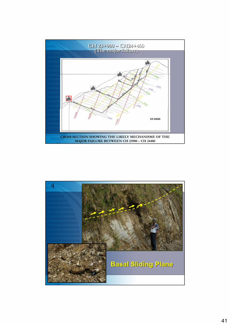
CH 23+900 – CH24+400 (The major failure)
CROSS SECTION SHOWING THE LIKELY MECHANISME OF THE MAJOR FAILURE BETWEEN CH 23900 – CH 24400
4
Basal Sliding Plane

42
• Ground water conditions and rainfall contributed significantly towards reducing the shearing resistance along discontinuities.
• The slope movement is reported to be still active, notably during and after prolonged rainfalls.
Case Study 4: Landslide at Pos Selim-Cameron Highland Highway
• The large-scale landslide is mainly attributed to unfavourableorientation of major discontinuities with respect to the cut slopeorientation.
• The failure is a deep seated failure and still active, notably duringheavy and prolonged rainfalls.
• Based on findings in the field and results of kinematic analysis,elements of instability still exists even though the slope is cut furtherinwardsinwards.

43
THANK YOU