Embed Size (px)
Citation preview

K.S.R.COLLEGE OF ENGINEERING, TIRUCHENGODE – 637 215. (Autonomous)
DEPARTMENT OF ELECTRICAL AND ELECTRONICS ENGINEERING
COURSE / LESSON PLAN SCHEDULE
NAME : Mrs.E.VANI & Mr.M.SUBRAMANI
CLASS : III-EEE
SUBJECT CODE : 16EE512
SUBJECT NAME : CONTROL SYSTEMS
A).TEXT BOOK:
1. A.NAGOOR KANI -“Control Systems”-Second Edition-RBA Publications, Chennai, 2009.
B). REFERENCES:
1. Ogata.K, Modern Control Engineering, 5th edition, PHI, New Delhi, 2009.
2. Norman S.Nise, Control Systems Engineering, 4th Edition, John Wiley, New Delhi, 2007.
3. Smarajit Ghosh, Control systems, Pearson Education, New Delhi, 2004.
4. Gopal.M, Control Systems, Principles and Design, Tata McGraw Hill, New Delhi, 2002.
5. S.Palani -“Control Systems Engineering”-Second Edition-RBA Publications, Chennai, 2009.
6. Nagoor kani. A, Control Systems, RBA publications (P) Ltd., 2007
7. Palani.S,Control Systems Engineering,Tata McGraw Hill Education Private Limited, New
Delhi,2nd Edition.
8. Benjamin C.Kuo, Automatic Control systems, Pearson Education, New Delhi, 2003.
C). LEGEND:
L - Lecture BB - Black Board
OHP - Over Head Projector pp - Pages
Tx 1 - Text book 1 LCD - Liquid Crystal Display
Rx 1 - Reference book 1 PC - Photo Copy
Sl.
No.
Lecture
Hour
Topics to be covered Teaching
Aid Required
Book No. / Page No.
UNIT-I SYSTEM CONCEPTS
1. L1 Types of system – Open and closed loop systems
BB Tx1pp(1.1-1.7),Rx 5 pp(1.4-1.17), Rx 1 pp(1-6),Rx4pp(7-9)
2. L2 Basic elements in control systems BB Rx 5 pp(1.2-1.3),Rx 4 pp(1-7),
3.
L3
Electrical analogous of mechanical translational system
BB
Tx1pp(1.7-1.16))(1.29–1.45),
Rx 5pp(2.3-2.21),
Rx2pp(77-87), Rx4(66-72)
4.
L4 Electrical analogous of mechanical rotational system
BB Tx1pp(1.17-1.22)(1.46-1.55),
Rx5pp(2.21-2.40),Rx2pp(87- 93),Rx4(72-85)
5. L5 Thermal system – Transfer function
BB Tx1pp(1.101-1.104)
6. L6 Synchros BB Tx1pp(2.5-2.10)

7. L7 AC & DC servomotors BB Tx1pp(2.22-2.29)
8. L8 Block diagram reduction techniques
BB Tx1pp(1.55-1.80),Rx5pp(4.1- 4.29),Rx1pp(54-64),
9.
L9
Signal flow graph
BB Tx1pp(1.81-1.101), Rx5pp -(4.30-
4.68),Rx1pp(62-72), Rx2pp(150-159),Rx3pp(89-100)
10. L10 Tutorial - I BB T x 1
11. L11 Tutorial - II BB T x 1
12. L12 Tutorial - III BB T x 1
UNIT-II TIME RESPONSE ANALYSIS
13.
L13 Standard test signals ,
Mathematical expression for
Standard test signals
BB Tx1pp(3.1-3.3),Rx 5pp(5.7-5.9) Rx 1 pp(194-197),Rx4(159)
14. L14 Types and Order of systems BB Tx1pp(3.4),Rx 5pp(5.62)
15. L15 Step response of first order systems
BB Tx1pp(3.8),Rx 5pp(5.2)
16.
L16, L17 Step response of second order
under damped, critically damped and over damped systems
BB
Tx1pp(3.11-3.16),Rx 5pp(5.22-5.25)
17.
L18 Time domain specification of
second order under damped systems
BB
Tx1pp(3.16-3.21),Rx 5pp(5.29-5.31)
18. L19, L20 Error coefficients, Generalised error series
BB Tx1pp(3.41-3.53),Rx 5pp(5.70-5.78)
19. L21 Steady state error and error constants.
BB Tx1pp(3.37-3.41),Rx 5pp(5.62-5.69)
20. L22 Tutorial - I BB T x 1
21. L23 Tutorial - II BB T x 1
22. L24 Tutorial - III BB T x 1
UNIT-III FREQUENCY RESPONSE ANALYSIS
23. L25 Frequency response of the system BB Tx1pp(4.1-4.2),Rx5pp(6.1-6.2), Rx 1 pp(327-328)
24.
L26, L27
Bode plot
BB Tx1pp(4.9-4.38),Rx 5pp(6.20-
6.47),Rx 1 pp(338-348), Rx2pp(544-566),Rx4(403-426)
25. L28 Polar plot BB Tx1pp(4.39-4.63),Rx5pp(6.2-6.22),Rx 1 pp(334-338),Rx4(427-434)
26.
L29
Constant M and N Circles
BB Tx1pp(4.67-4.72),Rx5pp(6.68-
6.73),Rx1pp(392-396),Rx2pp(608- 613),Rx3pp(622-627)
27. L30, L31 Determination of closed loop response from open loop response
BB Tx1pp(4.73-4.85),Rx5pp(6.73-6.80), Rx 1 pp(396-403), Rx3pp(627-631)
28. L32 Correlation between frequency and time response
BB Tx1pp(4.7-4.9),Rx5pp(6.16-6.19)
29. L33 Gain and phase margin specifications
BB Tx1pp(4.3-4.7), Rx5pp(6.48)
30. L34 Tutorial - I BB T x 1

KSRCE/EEE CONTROL SYSTEMS
31. L35 Tutorial - II BB T x 1
32. L36 Tutorial - III BB T x 1
UNIT-IV STABILITY OF CONTROL SYSTEM
33. L37 Characteristics equation BB Tx1pp(5.1-5.3), Rx5pp(7.6)
34. L38 Location of roots in S plane for
stability BB Tx1pp(5.3-5.8)
35. L39 Routh-Hurwitz Criterion BB Tx1(5.9-5.26),Rx5pp(7.8-
7.23),Rx1pp(277-287)
36. L40, L41 Root locus construction BB Tx1pp(5.63-5.99),Rx 5pp(8.1-8.66),
Rx 1 pp(298-331),Rx4pp(270-302)
37. L42 Effect of pole, zero addition BB Rx5pp(8.55-8.57)
38. L43 Gain margin and phase margin BB Tx1pp(5.57-5.58)
39.
L44, L45
Nyquist Stability Criterion
BB
Tx1pp(5.27-5.56),Rx5pp(7.24-
7.58),Rx 1 pp(381-394), Rx2pp(517-
544),Rx4(450-454)
40. L46 Tutorial - I BB T x 1
41. L47 Tutorial - II BB T x 1
42. L48 Tutorial - III BB T x 1
UNIT-V COMPENSATOR DESIGN AND CONTROLLERS
43. L49 Performance criteria BB Tx1pp(6.1- 6.4)
44. L50 Lag network BB Tx1pp(6.4-6.8), Rx5pp(9.9-9.10)
45. L51 lead network BB Tx1pp(6.28-6.32), Rx5pp(9.2-9.4)
46. L52 lag-lead networks BB Tx1pp(6.53-6.55), Rx5pp(9.14-9.16)
47. L53, L54 Lead,Lag compensator design
using Bode plots BB Tx1pp(6.4-6.88), Rx5pp(9.4-9.25)
48. L55, L56 Lead-lag Compensator design
using Bode plots BB Tx1pp(6.4-6.88), Rx5pp(9.4-9.25)
49. L57 P, PI, PID controllers BB Tx1pp(5.1-5.3), Rx5pp(7.6)
50. L58 Tutorial - I BB T x 1
51. L59 Tutorial - II BB T x 1
52. L60 Tutorial - III BB T x 1
UNIT-I SYSTEM CONCEPTS (CO1)
1. State the mason’s gain formula for signal flow graph. (Remembering)
Overall gain, T=
T=T(s)=Transfer function of the system
k- No. of forward paths in the signal flow graph.
Pk- Forward path gain of kth forward path
∆= 1-[sum of individual loop gains] + [sum of gain products of all possible combinations
of two non touching loops]-[sum of gain products of all possible combinations of
three non touching loops] +…
∆k = ∆ For that part of the graph which is not touching kth forward path.

KSRCE/EEE CONTROL SYSTEMS
2. What are the basic components of an automatic control system? (Remembering)
The components of feedback control system are plant, feedback path elements, error detector and
controller.
3. Determine the transfer function V0(S)/Vi(S) of electrical system.(Evaluating)
V0(S)/Vi(S) = [1+R2C2S]/[(R1+R2)C2S+1]
4. Write the mathematical model of the given mass, spring and dashpot element in fig.
(Remembering)
F (t) = Mdx/dt+fdx/dt+Kx F(S) =MS2X(S) +FSX(S) +KX(S)
5. Define transfer function. (Remembering)
The T.F of a system is defined as the ratio of the Laplace transform of output to Laplace transform of
input with zero initial conditions.
6. Draw a closed loop control system. (Remembering)
7. What is an error detector? (Remembering)
Error detector is a device which is used to generate the error signal proportional to the difference
between reference signal and feedback signal.
8. Find the output for the block diagram given below: (Evaluating)
9. Define open loop and closed loop control system. (Remembering)
The control system in which the output quantity has no effect upon the input quantity is called open
loop control system. This means that the output is not feedback to the input for correction. The control
system in which the output has an effect upon the input quantity so as to maintain the desired output
value is called closed loop control system. The output is feedback to the input for correction.
10. Write the rule for eliminating negative feedback loop. (Remembering)
11. What is meant by linear time invariant system? (Remembering)
A system is said to be invariant if its input, output characteristics do not change with time. A linear
time invariant system can be represented by constant coefficient differential equations. (In linear time
varying systems the coefficients of the differential equation governing the system are function of time.)
12. Write the analogous electrical elements in force voltage analogy for the elements of mechanical
translational system. (Remembering)
Force-voltage e, Velocity v-current I; Displacement x-charge q; Frictional coefficient B-Resistance R
Mass M- Inductance L; Stiffness K-Inverse of capacitance 1/C
13. What is the mathematical model of a system? (Remembering)
A control system is collection of physical objects connected together to serve an objective. The input
output relations of various physical components of a system are governed by differential equations.
The mathematical model of a control system constitutes a set of differential equations. The response
or output of the system can be studied by solving the differential equations for various input
conditions.
KSRCE/EEE CONTROL SYSTEMS
14. Write the analogous electrical elements in torque voltage analogy.(Remembering)
Torque T == Voltage, e B == R
Angular Velocity, == Current, i J == L
Angular displacement == Charge, q K == 1/C
15. Write any two advantages of block diagram representation. (Remembering)
(i) Function performed by each component is represented with blocks, so TF of each component is
determined separately. (ii) Easy to find overall transfer function of any order.
16. What are the different types of feedback control system? (Remembering)
(i) Positive feedback (ii) Negative feed back
17. Write advantage and disadvantages of transfer function.( Remembering)
Advantages: It is independent of input and depends only on system parameters but the output of a
system depends on input. Disadvantages: (i) It is defined under zero initial conditions.(ii)It is
applicable to LTI systems only. (iii) It is restricted to single input and output systems.(iv)Does not
provide information regarding the internal state of the system.
18. Write analogous for V, I, L, R in translational mechanical system. (Understanding)
Force-Voltage Force-Current
V- Force Velocity
I- Velocity Force
L- Mass 1/k
R- B 1/B
19. What is control system? (Remembering)
A system consists of a number of components connected together to perform a specific function. In a
system when the output quantity is controlled by varying the input quantity then the system is called
control system.
20. What are the basic elements used for modeling mechanical translational system & mechanical
rotational System? (Remembering)
Mechanical translational system: Mass, spring and dashpot.
Mechanical rotational system: Moment of inertia J, dashpot with rotational frictional coefficient B
and Torsional spring with stiffness K.
21. What is block diagram? (Remembering)
A block diagram of a system is a pictorial representation of the functions performed by each
component of the system and shows the flow of signals. The basic elements of block diagram are
block,branch point and Summing point.
22. What is a signal flow graph? (Remembering)
A signal flow graph is a diagram that represents a set of simultaneous algebraic equations .By taking
L.T the time domain differential equations governing a control system can be transferred to a set of
algebraic equations in s-domain.
23. What is transmittance? (Remembering)
The transmittance is the gain acquired by the signal when it travels from one node to another node in
signal flow graph.
24. What is sink and source? (Remembering)
Source is the input node in the signal flow graph and it has only outgoing branches. Sink is an output
node in the signal flow graph and it has only incoming branches.
25. Define non touching loop. (Remembering)
The loops are said to be non touching if they do not have common nodes.
26. Distinguish between open loop and closed loop system (Understanding)
Open loop Closed loop
1.Innaccurate 1.Accurate
2.Simple and economical 2. Complex and costlier
3.The changes in output due to external
disturbance are not corrected
3. The changes in output due to external
disturbances are corrected automatically
4.They are generally stable 4. Great efforts are needed to design a stable
system
27. What is Servomechanism? (Remembering)
Servomechanism represents the branch of feedback control system in which the output is either
mechanical positioning or its time derivatives such as velocity or acceleration. Automatic positioning
of anti-aircraft guns, radar antenna, rudders in ships is some example of servomechanism.
28. What are advantages and disadvantages of feedback control system?
(Remembering)

KSRCE/EEE CONTROL SYSTEMS
Adv :(i).They are more accurate (ii)It rejects external disturbances and noise.(iii).It acts very fast
which is essential for certain class of control systems.
Disadv :(i). The overall gain of the system is reduced.(ii).Feedback system are generally less stable
Than open loop systems.(iii).The system tries to correct itself which sometimes leads the system to
oscillate.
29. What is path gain and loop gain of a signal flow graph?( Remembering)
Path gain is the product of the branch gains encountered in traversing the path. Loop gain is defined as
the product of all branch gains of the branches constituting the loop.
30. Mention the disadvantages of block diagram representation. (Remembering)
(i).Interaction blocks. (ii).Reciprocity and non reciprocity. (iii).It is not unique.
31. What are synchros? (Remembering)
It is rotating device which produces a correlation between an angular position and voltage. A synchro
pair consists of a synchro transmitter and a synchro receiver.
32. What are the different types of stepper motor? (Remembering)
(i).Variable reluctance stepper motor. (ii).Permanent magnet steeper motor. (iii).Hybrid stepper motor.
33. What do you meant by analogous system? (Remembering)
Mechanical, thermal, Hydraulic and electromechanical systems are represented and studied by their
equivalent electrical circuits which are more easily constructed than the corresponding models. The
equations of electrical and the corresponding mechanical or hydraulic systems are compared and from
that the equivalent electrical circuits are obtained. If the differential equations of both electrical and
mechanical or hydraulic systems are equal, then one system is said to be analogous to the other.
34. What is the use of mason’s gain formula? (Remembering)
(i). For Complicated system to solve the signal flow graph. (ii). To determine the gains between output
node and any other non-input node.
35. What type of feedback is preferred in control system and why? (Remembering)
Negative feedback is preferred in control system.
The negative feedback results in better stability in steady state and rejects any disturbance signals. It
also has low sensitivity to parameter variations. Hence negative feedback is preferred in closed loop
control systems.
36. List two advantages of signal flow graph. (Remembering)
1. The advantage in signal flow graph method is that, using Mason’s gain formula the overall gain of
the system can be computed easily. 2. This method is simpler than tedious block diagram reduction
techniques.
37. Name the two control modes in which d.c.motors are used ? (Remembering)
1. Armature control. 2. Field control
38. What are the advantages of the closed loop control system? (Remembering)
1. The closed loop systems are accurate even in the presence of non-linearities.
2. The sensitivity of the systems may be made small to make the system more stable.
3. The closed loop systems are less affected by noise.
39. What are the properties of signal flow graphs? (Remembering)
1. Signal flow graph is applicable to linear systems only.
2. The algebraic equations which are used to construct signal flow graph must be in the form
of cause and effect relationship.
3. A node in the signal flow graph represents the variable or signal.
4. A node adds the signals of all incoming branches and transmits the sum to all outgoing
branches. 16 MARK QUESTIONS
1. Using mason’s gain formula find C/R. (Evaluate)
2. Find C/R by block diagram reduction technique. (Evaluate)

KSRCE/EEE CONTROL SYSTEMS
3. Obtain the output of the system shown in fig. (Evaluate)
4. Obtain the analogous electrical network for the system given below. (Evaluate)
5. Explain the rules for block diagram reduction and hence find the transfer function for the Following
block diagram. (Evaluate)
6. Determine the transfer function Y2(S)/F(S) of the system shown in fig. (Evaluate)
7. Reduce the block diagram shown in fig and obtain C(S)/R(S).
(Evaluate)
8. Obtain the transfer function of the mechanical system as shown in fig (Evaluate)

KSRCE/EEE CONTROL SYSTEMS
9. For the signal flow graph given in fig. evaluate the closed loop transfer function of a system.
(June 2015) (Evaluate)
10. Explain open loop and closed loop with example, compare and merits and demerits.(Understanding)
11. Find the transfer function of field controlled D.C.Servo motor. (Understanding)
12. Discuss the mathematical modeling of AC servomotors. (Understanding)
13. Find the transfer function of armature controlled D.C.Motor. (Evaluate)
14. Using block diagram reduction technique find the closed loop transfer function relating to output and
input. (Evaluate)
15. Obtain the transfer function of the mechanical system shown below.
(Evaluate)
16. For the given signal flow graph find C(s)/R(s) using Mason’s gain formula.
(Evaluate)
17. (a) Find the transfer function Y2(s) / F(s) of the mechanical system shown in fig
(Evaluate)

KSRCE/EEE CONTROL SYSTEMS
17.(b) Find C(s) / R(s) using Mason’s gain formula for the signal flow graph as shown in fig
(Evaluate)
18. Obtain C(s) / R(s) using block diagram reduction rules for the system given in fig. (Evaluate)
19. Consider the signal flow graph shown in figure .Determine C(s)/R(s) Using Mason’s gain formula.
(Evaluate)
20. Write the differential equations governing the mechanical rotational system shown in figure
(Evaluate)
*********************************************
UNIT-II TIME RESPONSE ANALYSIS (CO2)
1. Define Rise time of an under damped second order system. (Remembering)
The time taken for response to rise from 0% to 100% for the very first time is known as rise time. For
under damped system it is the time taken for response to rise from 0% to 100%, for over damped
system it is the time taken for response to rise from 10% to 90%, for critically damped system it is the
time taken for response to rise from 5% to 95%.

KSRCE/EEE CONTROL SYSTEMS
2. Determine the %Mp of system, whose closed loop transfer function is 1000/ (S2+34.5S+1000), for
Step input.(Evaluating)
Maximum peak overshoot , From TF δ = 0.547, e-2.05=0.1287
3. What is a type and order of a system?(Remembering)
The type of a system is the number of poles of loop transfer function lying at origin of S-Plane. But
the order of a system is the number of poles of transfer function.
4. The specifications given on a certain 2nd order feedback control system is the overshoot of the step
response should not exceed 25%. What are the overshoot limiting values of the damping ratio and
peak resonance. (Remembering) δ = 0.4 Mr=1.363
5. Name the test signals used in control system. (Remembering)
Step, Ramp, Parabolic, impulse and sinusoidal signals
6. Define Steady state error. (Remembering) The steady state error is the value of the error signal e (t), when t tends to infinity. The steady state
error is a measure of system accuracy. These errors arise from the nature of inputs, type of system and
from non linearity of system components.
7. List out any four time domain specifications. (Remembering) The time domain specifications are
i. Delay time ii. Rise time iii. Peak time iv. Peak overshoot
8. What is the expression for unit step response of the standard second order under damped
system? (Remembering)
t+θ)
9. What may be the damping ratio when the % of overshoot of the system is 100%?
(Remembering) δ = 0
10. How the system classified according to damping factor? (Understanding) Case 1: Undammed system, δ = 0, Case 2: Under damped system, δ < 0,
Case 3: Over damped system, δ > 0, Case 4: Critically damped system, δ = 1.
11. Differentiate transient response & steady state response. (Understanding) The transient response is the response of the system when the system changes from one state to
another. The steady state response is the response of the system when t tends to infinity.
12. What is the drawback of static coefficients? (Remembering) The main drawback of static coefficient is that it does not show the variation of error with time and
input should be standard input.
13. What are the three constants associated with a steady state error. (Remembering) Positional error constant, Velocity error constant, Acceleration error constant
14. What are the main advantages of generalized error co-efficient? (Remembering) The Generalized error co-efficient gives (i). Steady state error as a function of time. ii) Steady state
Error can be determined from any type of input
15. What are the effects of adding a zero to a system? (Remembering) Adding a zero to a system results in pronounced early peak to system response thereby the peak
overshoot increases appreciably.
16. What is a dominant pole? (Remembering) The dominant pole is a pair of complex conjugate pair which decides the transient response of the
system.
17. What are static error constants? (Remembering)
The Kp, Kv and Ka are called static error constants.
Positional error constant, Kp = S 0
Velocity error constant, Kv = S 0
Acceleration error constant, Ka = S 0 s2G(s) H(s)
18. Define peak overshoot. (Remembering) It is defined as the ratio of the maximum peak value measured from final value to final value. Let final
Value = C(∞), Maximum value = C(tp) Peak overshoot, MP=C(TP)-C(∞)/C(∞)
19. Define settling value. (Remembering) It is defined as the time taken by the response to reach and stay within a specified error and the error
is usually specified as % of final value. The usual tolerable error is 2% or 5% of the final value.
20. What is the effect of adding a pole to a second order system? (Remembering)
KSRCE/EEE CONTROL SYSTEMS
The addition of pole to the original second order system increases the rise time but decreases the
overshoot.
21. A unity feedback system has an open loop transfer function G(s) = 10/s(s+5). Find un damped
natural Frequency and damping ratio. (Evaluate) For unity feedback system H(s) = 1
Therefore Closed Loop transfer function = = =
= 10 , 2ς ωn = 5
Natural frequency ωn = = 3.1622 rad/sec Damping ratio ς = 5/2 = 0.79
22. What is the steady state error of a first order system for a unit step input and unit ramp input?
(Remembering) Unit Step Input ess=0, Unit Ramp ess =1/KV
23. What is meant by characteristic equation? (Remembering) The characteristic equation of a system is defined as the equation obtained by setting the characteristic
denominator polynomial of the closed loop transfer function to zero. It determines the stability of the
system and also transient and steady state responses of the system.
24. What does the time constant of a system indicate? (Remembering)
Is the rise time characterizing the response to a time-varying input of a first-order, linear time-
Invariant (LTI) system. The time constant is the main characteristic unit of a first-order LTI (linear
time- invariant) system.
25. With reference to time response of a control system, define ‘peak time’ (Remembering) It is the time required for the response to reach its peak value.
26. Give the steady state errors to a various standard inputs for type 2 system. (Remembering)
Unit step ess=0, Unit Ramp ess=0, unit parabolic ess=1/Ka
16 MARK QUESTIONS
1. The open loop transfer function of a unity feedback control system
G(S)=K(1+0.5S)(1+2S)/S2(S2+4S+5).Determine the position, velocity and acceleration error constants
and steady state error for (i) Unit ramp (ii) Unit step and (iii) Unit parabolic inputs.
(Evaluate) 2. A system is described by [d2y / dt2] + 8[dy / dt] + 25y (t) =50x (t) Evaluate the response and maximum
output for a step of 2.5 units. (Evaluate)
3. (i) Certain measurements were conducted on a servo mechanism which show the system response as
c(t)=1+0.2e-60t-1.2e-10t when subjected to a unit step input.(1) Find the expression for closed loop transfer
function. (2) Obtain the undamped natural frequency and damping ratio. (ii) Determine the
value of ‘k’ and ‘a’ such that the system has a damping ratio of 0.7 and an undamped natural frequency
of 4 rad/sec for the system shown in fig. (Evaluate) 4. Determine the time response specification and expression for output for unit step input to a system
having the system equation as follows [d2y / dt2] + 5[dy / dt] + 16y=9x. Assume zero initial condition.
(Understanding) 5. The unity feedback system is characterized by an open loop transfer function G(S) =K/S(S+10).
Determine the gain K, so that the system will have a damping ratio of 0.5. For this value of K,
determine settling time, peak overshoot and time to peak overshoot for a unit step-input. (Evaluate) 6. OLTF G(S) =10/(S+2) (S+3), what type of input signal gives constant steady state error and calculate its
value. (Analyze)
7. Determine the value of ‘k’ and ‘a’ such that the system has a Mp% of 1.04 and Resonant frequency of
11.55 rad/sec and settling time bandwidth for the system shown in fig (Evaluate)
8. Explain the steady state error and generalized error coefficients. (Understanding)
9. A unity feedback system has an open loop transfer function G(s)=K/s(s+10) if the damping ratio is 0.5,
determine (i).The value of K.(ii).Peak overshoot.(iii).Time to peak overshoot.(iv).Settling
time. (Evaluate)
10. For a unity feedback system whose G(s)=1/s(s+1) the input signal is r(t)=4+6t+2t3 Find generalized
error coefficients. (Evaluate)

KSRCE/EEE CONTROL SYSTEMS
11. Derive the unit step response of the second order system for the under damped case. (Understanding) 12. Obtain the unit step response and unit impulse response of the following system
C(s)/R(s) =10/(s2+2s+10. (Understanding)
13. An unity feedback system has G(s)=1/s(1+2s).The input to the system is described by
r(t)=2+4t+6t2+2t3.Determine the generalized error coefficients and express the steady state error as a
function of time. (Understanding)
14. Obtain the response of second order under damped system with unit step input. (Understanding)
15. A second order system is represented by the transfer function C(S)/R(S) =1/(Js2+Fs+K).A step input of
10N.m is applied to the system and the results are given below. (i).Maximum overshoot=6% (ii).Time
at which peak overshoot occurs=15sec (iii).The steady state value of the output is 0.5rad.Determine the
values of J,F,and K. (Evaluate)
16. (a) A system has the following transfer function C(s) / R(s) = 20 / (S+10). Determine its unit step
Response with Zero initial conditions. (Evaluate)
(b) A unity feedback system has G(s) = 40(s+2) / s(s+1)(s+4). Determine (i) Type of the system
(ii) Order of system (iii) all error coefficients. (Evaluate)
17.The open loop transfer function of a unity feedback control system is given by G(s)=K/s(sT+1) where
K and T are positive constants. By what factor should the amplifier gain be reduced so that the peak
overshoot of unit step response of the system is reduced from 75% to 25%.(Apply) .
18.A certain unity negative feedback control system has the following forward path transfer function
G(s) = K(s+2) / s(s+5)(4s+1).The input applied is r(t)=1+3t find the minimum value of K so that the
steady state error is less than 1(Apply)
19. A Unity feedback system has the forward transfer function G(s)=K1(2s+1)/s(5s+1)(1+s)2. The input
r(t)=(1+6t) is applied to the system. Determine the minimum value of K1,if the steady state error is to
be less than 0.1. (Analyze)
20. For a unity feed back control system thee open loop transfer function G(s)=10(s+2/S2(S+1) find
1. Position, velocity and acceleration error constant
2. Steady state error when the in put R(s)=(3/s)-(2/s2)+(1/3s3) (Evaluate)
21. Derive the time domain specifications of second order system (Understanding)
************************************
UNIT-III FREQUENCY RESPONSE ANALYSIS (CO3)
1. Sketch the polar plot of the function G(S) H(S) =10/s(1+S)(1+2S) (Remembering)
2. What are the frequency domain specifications? (Remembering) The frequency domain specifications are
i) Resonant peak. ii) Resonant frequency iii) Band width iv) cut off rate v) gain margin vi) phase
Margin
3. The damping ratio and natural frequency of oscillation of a second order system is 0.5 and 8
rad/sec respectively. Calculate the resonant peak and resonant frequency. (Analyze)
Mr=1.1547, ωr=5.656
4. How is phase margin determined from bode plot? (Analyze)
The phase margin is the amount of phase lag at the gain cross over frequency required to bring system
to the verge of instability.
5. Define Phase margin and gain margin (Remembering)
The phase margin is the amount of phase lag at the gain cross over frequency required to bring system
to the verge of instability.
The gain margin, kg is defined as the reciprocal of the magnitude of the open loop transfer function at
phase cross over frequency. Gain margin kg = 1 / G(j ω pc).
6. Define –resonant Peak & Resonant frequency (Remembering)
The maximum value of the magnitude of closed loop transfer function is called resonant peak.
= . The frequency at which resonant peak occurs is called resonant
frequency. = ( )

KSRCE/EEE CONTROL SYSTEMS
7. What is the relationship between resonant peak and damping ratio? (Remembering)
Damping ratio is inversely proportional resonant peak. =
8. List out the advantages of frequency response analysis. (Remembering)
(i) The absolute and relative stability of the closed loop response cab be estimated from the
knowledge of the open loop frequency response.
(ii) The TF of complicated functions can be determined experimentally by frequency response
tests.
(iii) The design and parameter adjustment can be carried easily.
(iv) The corrective measure for noise disturbance and parameter variation can be easily carried.
(v) It can be extended to certain nonlinear system.
(vi) The practical testing of system can be easily carried with available sinusoidal signal
generators and precise measurement equipments.
9. What is meant by frequency response? ( Remembering)
The magnitude and phase function of sinusoidal transfer function of a system are real function of
frequency ω, and so they are called frequency response.
10. What are the main advantages of Bode plot? (Remembering)
The main advantages are:
i) Multiplication of magnitude can be in to addition.
ii) A simple method for sketching an approximate log curve is available.
iii) It is based on asymptotic approximation. Such approximation is sufficient if rough information
on the frequency response characteristic is needed.
iv) The phase angle curves can be easily drawn if templates for the phase angle curve of 1+ jω is
available.
11. Define bandwidth and cut off rate. (Remembering)
The bandwidth is the range of frequencies for which the system gain is more than -3db. The slope of
log magnitude curve near the cut off frequency is called cut of rate.
12. What is gain and phase cross over frequency? (Remembering)
The gain cross over frequency is the frequency at which the magnitude of the open loop transfer
function is unity. The phase cross over frequency is the frequency at which the phase of the open loop
transfer function is 180 degree.
13. Write a short note on correlation between time and frequency response. (Remembering) There exists a correlation between time and frequency response of first or second order systems. The
frequency domain specification can be expressed in terms of the time domain parameters ω and δ. For
peak overshoot in time domain there is a corresponding resonant peak in frequency domain.
14. Define corner frequency. (Remembering)
The magnitude plot is approximated by asymptotic straight lines. The frequencies corresponding to the
meeting point of asymptotes are called corner frequency. The slope of the magnitude plot changes at
every frequency.
15. What is minimum phase system? (Remembering) The minimum phase systems are systems with minimum phase transfer function. In minimum phase
transfer functions, all poles and zeros will lie on the left half of S-plane.
16. What is all pass system? (Remembering) The all pass systems are systems with all pass transfer functions. In all pass transfer functions, the
Magnitude is unity at all frequencies and the transfer function will have anti-symmetric pole zero
Pattern.
17. Define bode plot and polar plot. (Remembering)
The bode plot is a frequency response plot of the transfer function of a system. It consist of two plots-
magnitude and phase plot. The magnitude plot is a plot drawn between magnitudes in dB versus
frequency. The phase plot is a plot drawn between phase in degree versus frequency. The polar plot of
a sinusoidal transfer function is a plot of the magnitude of G (jω) versus the phase angle/argument of
G (jω) on polar or rectangular coordinates as ω is varied from zero to infinity.
18. In minimum phase system, how the start and end of polar plot are identified?(Analyze) For minimum phase transfer functions, with only poles, the type number of the system determines the
quadrant in which the polar plot starts, and the order of a system determines the quadrant in which the
polar plot ends.

KSRCE/EEE CONTROL SYSTEMS
19. Draw the polar plot of type Zero first order system G(S) = 1 /(1 +ST). (Remembering)
20. Draw the bode plot of , G(S)=K/Sn (Remembering)
21. Define frequency response analysis. (Remembering)
The frequency response is a steady state output of the system, when the input is a sinusoidal signal.
22. Define M and N circles. (Remembering)
The magnitude M of closed loop transfer function with unity feedback will be in the form of circle in
complex plane for each constant value of M. The families of these circles are called M circles.
Let N=tan α where α is the phase of closed loop transfer function with unity feedback. For each
constant value of N, a circle can be drawn in the complex plane. The families of these circles are
called N circles.
23. What do you mean by a decade as referred in bode plot? (Remembering)
The bode plot is a straight line with slope denoted as decibel/decade (dB/dec).The word decade comes
from the Latin word meaning 10.The word decade means an increase in frequency by a factor of
10. So, slope is measured in dB/dec.
16 MARK QUESTIONS
1. Determine resonant frequency and peak resonance for the system whose transfer function is given by
C(S)/R(S)=5/(S2+2S+5). (Evaluate) 2. Draw the bode plot for a unity feedback system G(S)=K(S+0.3)/(S+4)(S2+30S+20) where K=2000.
Determine the value of K to obtain phase margin of 30degree. (Evaluate)
3. A unity feedback control system has G(S)=K/S(S+4)(S+10). Draw the bode plot and find the value of K
when gain margin is 10db. (Evaluate)
4. Bode plot G(S)=10/S(0.4S+1)(0.1S+1).
5.Sketch the polar plot for the system whose open loop transfer function is G(S) = [1/(S+1)(2S+1)].
(Evaluate)
6. Draw Bode plot G(S) = 0.75(1+0.2S)/S(1+0.5S)(1+0.1S) (Nov 06), G(S) = K(s+3/s(s+1)(s+2).
(Evaluate)
7. Derive frequency domain specifications for second order under damped system with step input.
(Understanding)
8. Explain the correlation between time and frequency responses for second order systems.
(Understanding)
9. For an unity feedback system with closed loop transfer function G(S)/1+G(S) derive the equation for the
locus of constant M circles and constant N circles. (Understanding)
10.Write the procedure to obtain Nichol’s chart from constant M circles. (Understanding)
11.Write a MATLAB program to examine stability using Bode plot for the given transfer function
G(S)=20e -0.2s/s(s+2)(s+8) and explain the code. (Analyze)
12. Draw the Bode plot of the open loop transfer function G(s)=200(s+10)/s(s+5)(s+20) (Evaluate)
13. Determine the value of K for a unit feedback control system having open loop transfer function
G(s) H(s) =k/s(s+2)(s+4) such that (i)Gain margin=20db.(ii).Phase margin=60degree.(Evaluate)
14. Sketch the Bode plot for the given transfer function G(s) = 80/s(s+4)(s+10) Find PM&GM. (Evaluate)

KSRCE/EEE CONTROL SYSTEMS
15. For a unity feedback system G(s) = 800 (s+2) / s2(s+10) (s+40). Sketch the bode plot and comment on
its stability. (Evaluate)
16. Sketch the root locus for the system having G(s) H(s) = K/ s(s2+2s+2) (Evaluate)
17. The open loop transfer function of a unity feedback system is given by G(s) =1/s (1+s) (1+2s). Sketch
the polar plot and determine the gain margin and phase margin. (Evaluate)
18. A unity feedback system has open loop transfer function, G(s) =20/s(s+2) (s+5). Using Nichols chart,
determine the closed loop frequency response and estimate Mr, ωr and ωb. (Evaluate)
19. (a).For the given transfer function G(s)=10(1+5s)/[(2s+3)(s+10)].Identify the corner frequencies and
initial &final slope of log magnitude graph.(b).What are the advantages and drawbacks of bode plots
over that of polar plot? (Evaluate)
20.Given G(s)=Ke-0.2s/s(s+2)(s+8),find K for the following two cases:(i).Gain margin equalto6db.(ii).Phase
margin equal to45 degree. (Evaluate)
****************************************
UNIT-IV STABILITY OF CONTROL SYSTEM (CO4)
1. Define Routh Hurwitz stability criterion. (Remembering)
Routh stability criterion states that the necessary and sufficient condition for stability is that all of the
elements in the first column of the routh array should be positive. If this condition is not met, the system
is unstable and the number of sign changes in the elements of the first column of routh array corresponds
to the number of roots of characteristics equation in the right half of the S-plane.
2. Determine the stability of the following system using routh criterion. (Analyze) (A) G(S)H(S)=1/(S+2)(S+4)
S2 1 9 1ST column of the routh array is positive. System is stable.
S1 6
S0 9
(B) G(S)H(S)=9/S2 (S+2)
S3 1 0 1ST column of the routh array is not positive. System is unstable.
S2 2 9
S1 -9/2 0
S0 9
3. The characteristics equation of a feedback control system is S4+22S3+10S2+2S+K =0. Determine
the range of K for which the system is stable. (Analyze) S4 1 10 K
S3 22 2 0 System is stable for the range of K value 0 < K< 0.9
S2 9.9 K
S1 2-2.22K
S0 K
4. What are the applications of root locus method? (Remembering)
It is used to design a control system with desired performance characteristics; it can be achieved by
adjusting the location of its closed loop poles in the S-plane by varying one or more system parameters.
(i) It is used for stability analysis. The range of values of K, for a system can be determined.
(ii) It is easier to study relative stability. The dominant roots are used to estimate the damping ratio
and natural frequency of oscillation.
5. Define asymptotic stability. (Remembering)
A system is asymptotically stable if in the absence of the input, the output tends towards zero
irrespective of initial conditions.
6. State the rule for find out the root loci on real axis. (Remembering)
To find a root locus on real axis, choose a test point on real axis. If the total number of poles and zeros
on the real axis to the right of this test point is odd number then the test point lies on the root locus. If it
is even then the test point does not lie on the root locus.
7. Write the condition for unstable system. (Remembering)
If any root of the characteristics equation has a positive real part or if there is a repeated root on the
Imaginary axis then the system is unstable.
8. Explain the relative stability of the system. (Remembering)
The Relative stability indicates the closeness of the system to stable region. It is an indication of
strength or degree of stability.
9. Explain how the stability of system is determined from the routh table. (Remembering)
The necessary and sufficient condition for stability is that all of the elements in the first column of the
routh array should be positive.

KSRCE/EEE CONTROL SYSTEMS
10. Define system stability (Remembering)
The term stability refers to the stable working condition of a control system. Every working system is
designed to be stable. In a stable system the response or output is predictable, finite and stable for a
given input. A system is stable if its output is bounded for any bounded input.
11. What is Root locus? (Remembering)
The path taken by a root of characteristics equation when open loop gain K is varied from 0 to ∞ is
called root locus.
12. What is a dominant pole? (Remembering)
The dominant pole is a pair of complex conjugate pair which decides transient response of the system.
In higher order systems the dominant poles are very close to origin and all other poles of the system are
widely separated and so they have less effect on transient response of the system.
13. What is the effect of adding a zero to a system? (Analyze)
Adding a zero to a system increases peak overshoot appreciably.
14. What is limitedly stable system? (Remembering)
For a bounded input signal if the output has constant amplitude oscillations. Then the system may be
stable or unstable under some limited constraints such a system is called limitedly stable system.
15. What is principle of argument? (Remembering)
The principles of argument state that let F(S) be an analytic function and if an arbitrary closed contour
in the clockwise direction is chosen in the s-plane so that F(S) is analytic at every point of the contour.
Then the corresponding F(S)-Plane contour mapped in the F(S) plane will encircle the origin N times
in the anticlockwise direction, where N is the difference between number of poles and zeros of F(S)
that are encircled by the chosen closed contour in the s-plane.
16. State and explain Nyquist stability criterion. (Understanding)
If the Nyquist plot of the open loop transfer function G(s) corresponding to the nyquist control in the
S-plane encircles the critical point –1+j0 in the counter clockwise direction as many times as the
number of right half S-plane poles of G(s), the closed loop system is stable.
17. State-Magnitude criterion & Angle criterion. (Understanding)
Magnitude criterion: The magnitude criterion states that s=sa will be a point on root locus if for that
value of s , | D(s) | = |G(s)H(s) | =1
Angle criterion: The Angle criterion states that s=sa will be a point on root locus for that value of s,
angle of D(s) = angle of G(s) H(s) =odd multiple of 180°.
18. What are asymptotes? How will you find the angle of asymptotes? (Remembering)
Asymptotes are straight lines which are parallel to root locus going to infinity and meet the root locus
at infinity. Angles of asymptotes= ± ; q=0,1,2…..(n-m)
19. What is centroid? How the centroid is calculated? (Remembering)
The meeting point of asymptotes in real axis is called centroid. The centroid is given by,
Centroid=
20. What is a breakaway and break in point? How to determine them? (Remembering)
At breakaway points the root locus breaks from the real axis to enter into the complex plane. At break
in point the root locus enters the real axis from the complex plane. To find breakaway and break in
points, from an equation for K differentiate with respect to S. Then find dK/dS=0. The roots of
dK/dS=0 are break away or break in point provided for this value of root the gain K should be positive
and real.
21. What is BIBO Stability? (Remembering)
A system is Bounded input bounded output stable if all the roots of the characteristic equation lie in the
left half of the complex plane (LHP).
22. Mention the Advantages of Nyquist stability criterion. (Remembering)
(i).Relative stability of the system. (ii).Improving stability of the system (iii).the Nyquist locus gives
information concerning the frequency response of the system.
23. What is meant by critically stable system? (Remembering) A linear system is said to be critically stable if the Nyquist GH (jω) plot just crosses the (-1, 0) point.
In the time domain the system is critically stable if the roots lie in the imaginary axis.
24. List out the advantages of Root locus. (Remembering)
(i).Stability of the system. (ii).The transient response of the system. (iii).Gain adjustment with
Relatively small.
25. Define Gain Margin. (Remembering)
Gain margin is the amount of gain in decibels (dB) that can be added to the loop before the closed loop
system becomes unstable

KSRCE/EEE CONTROL SYSTEMS
26. Define Phase Margin. (Remembering)
Phase margin is defined as the angle in degrees through which the L (jw) plot must be rotated about
the origin so that the gain crossover passes through the (-1, j0) point.
27. Define the terms absolute stability and conditional stability. (Remembering)
If a system output is stable for all variations of its parameters, then the system is called absolutely
stable system. If a system output is stable for a limited range of variations of its parameters, then the
system is called conditionally stable system.
28. Check whether the system with characteristics equation is, S4+8S3+18S2+16S+5= 0 is stable.
(Analyze)
The elements of first column of routh array it is observed that all the elements are positive and there
is no sign change .Hence all the roots are lying on the left half of s-plane and the system is stable.
16 MARK QUESTIONS
1. Check the stability of a system with characteristics equation S4+S3+20S2+9S+100 = 0 using Routh
Hurwitz criterion. (Apply)
2. List all the rules to construct the root locus and explain. (Understanding)
3. Sketch the root locus for the system and comment on stability.
G(S) H(S) =K(S+4)(S+5)/(S+1)(S+1),K>0. (Analyze)
4. Using routh criterion, determine the stability of the system whose characteristics equation is,
S4+8S3+18S2+16S+5= 0 (Analyze)
5. Explain the system stability with respect to location of roots on s-plane (Understanding)
6. Briefly explain the effect of adding a pole and a zero. (Understanding)
7. (i) Explain the procedure to determine the stability of the closed loop system when open loop transfer
function G(S) H(S) is given using Nyquist stability criterion. (ii) Rules and Explanation.
8. Apply nyquist stability criterion to the system with loop transfer function G(S) H(S) =4S+1/S (1+S)
(1+2S) and its stability.(Apply)
9. Explain mapping theorem and principle of argument and hence draw the Nyquist plot for the system
whose open loop transfer function is G(S)H(S)=1/S(S+2). (Apply)
10. Investigate the F(s) for stability using RH criterion (Apply)
(i).F(s)=s4+Ks2+(K+1)s+(K+2)s+2 (ii).F(s)=s4+s3+3s2+s+6 (iii).F(s)=s5+s4+2s3+2s2+6s+6
11. Sketch the root locus for the system with characteristic equation1+G(s) H(s) =
(Apply)
12. For each of the characteristics equation of feedback control system given, determine the range of k for
stability. Determine the value of k so that the system is marginally stable and the frequency of
sustained oscillations (i).s4+25s3+15s2+20s+k=0 (Dec 2015) (ii).s4+ks3+s2+s+1=0 (Apply)
13. Sketch the root locus of a feedback system whose open loop transfer function is given by
(i).G(s) H(s) =k/s(s+2) (s+3) (ii). G(s) H(s) =k/s(s+2) (s+10) Determine the range
of k for which closed loop system is stable using Routh stability Criterion. (Evaluate)
14. A unity feedback control system has G(s) = 10 / s(s+1) (s+2). Use Nyquist stability criterion and
determine whether the system is stable or not. (Evaluate)
15. Apply Routh’s criterion to test the stability of the system described the following characteristic
Equation. Also find number of roots falling in the right half of the s plane (i) s5-2s4+2s3+4s2-11s-10=0
(ii).s5+0.5s4+3s3+1.5s2+0.5s+0.5=0(iii).s6+2s5+8s4+12s3+20s2+16s+16=0
16. A certain unity negative feedback control system has the following open loop transfer function GH(s)
=K/[s(s+1) (s+3)]. Draw the root locus for 0<k<infinitive. (Evaluate)
17. Sketch the Nyquist plot for a system with open loop transfer function
G(s)H(s)=K(1+0.4s)(s+1)/(1+8s)(s-1)and determine the range of K for which the system is stable.
(Evaluate)
18. Sketch the root locus of the system having G(s)=k(s+3)/s(s+1)(s+2)(s+4)
(Apply)
***********************************************
UNIT-V COMPENSATOR DESIGN AND CONTROLLERS (CO5)
1. Mention the characteristics of PI controller. (Remembering) The PI controller is a device which produces a control signal consisting of two terms- one proportional
KSRCE/EEE CONTROL SYSTEMS
to error signal, another one proportional to integral of error signal.The PI controller increases the order
of a system by one, which results in reducing steady state error. But the system becomes less stable
than the original system.
2. Why derivative controller is not used in control system? (Analyze) The derivative controller produces a control action based on the rate of change of error signal and it
does not produce corrective measures for any constant error.
3. Write the equation of PID controller. (Remembering) Transfer function of PID controller = KP(1+TDS+1/TIS)
4. What are the different types of controllers? (Remembering) (i).P Controller (ii).PI controller. (iii).PD controller (iv).PID Controller
5. What is the effect of PD controller on system performance? (Remembering) The effect of PD controller is to increase the damping ratio of the system and so the peak overshoot is
reduced
6. What is compensation? (Remembering)
The compensation is the design procedure in which the system behavior is altered to meet the desired
specifications, by introducing additional device called compensator.
7. What is compensator? What are the different types of compensator? (Remembering) A device inserted into the system for the purpose of satisfying the specifications is called compensator.
The different types of compensators are lag compensator, lead compensator and lag-lead compensator.
8. Define lag compensator. (Remembering)
A compensator having the characteristics of a lag network is called lag compensator. If a sin signal is
applied to a lag compensator, then in steady state the output will have a phase lag with respect to input.
9. Define Lead compensator. (Remembering) A compensator having the characteristics of a lead network is called lead compensator. If a sin signal
is applied to a lead compensator, then in steady state the output will have a phase lead with respect to
input.
10. Define Lag-lead Compensator. (Remembering) A compensator having the characteristics of a Lag-lead network is called lag-lead compensator. If a
sin signal is applied to a lag- lead compensator, then in steady state the output will have both phase lag
and phase lead with respect to input.
11. Give the transfer function of Lag Compensator. (Remembering) Transfer function of lag compensator GC(S) = (S+1/T) / (S+1/βT)
12. Give the transfer function of Lead Compensator. (Remembering) Transfer function of lead compensator GC(S) = (S+1/T) / (S+1/αT)
13. Give the transfer function of Lead-Lag Compensator. (Remembering) Transfer function of lead compensator GC(S) = (S+1/T1) (S+1/T2) / (S+1/βT1) (S+1/αT2)
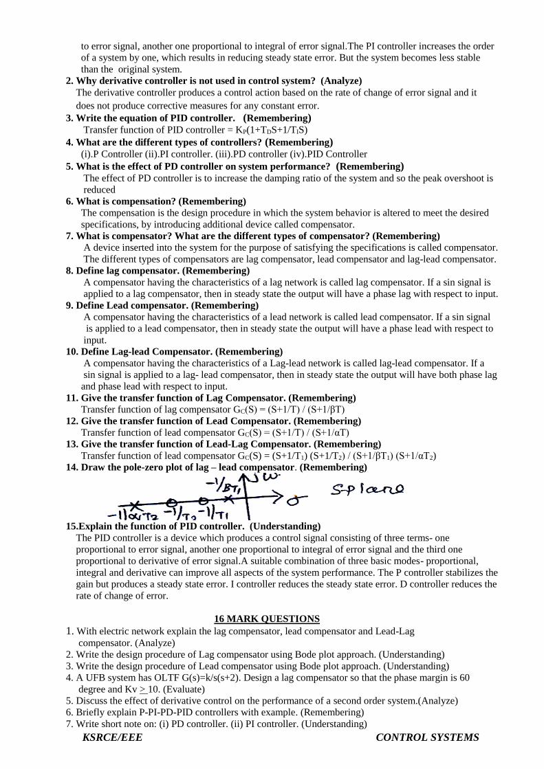
14. Draw the pole-zero plot of lag – lead compensator. (Remembering)
15.Explain the function of PID controller. (Understanding)
The PID controller is a device which produces a control signal consisting of three terms- one
proportional to error signal, another one proportional to integral of error signal and the third one
proportional to derivative of error signal.A suitable combination of three basic modes- proportional,
integral and derivative can improve all aspects of the system performance. The P controller stabilizes the
gain but produces a steady state error. I controller reduces the steady state error. D controller reduces the
rate of change of error.
16 MARK QUESTIONS
1. With electric network explain the lag compensator, lead compensator and Lead-Lag
compensator. (Analyze)
2. Write the design procedure of Lag compensator using Bode plot approach. (Understanding)
3. Write the design procedure of Lead compensator using Bode plot approach. (Understanding)
4. A UFB system has OLTF G(s)=k/s(s+2). Design a lag compensator so that the phase margin is 60
degree and Kv > 10. (Evaluate)
5. Discuss the effect of derivative control on the performance of a second order system.(Analyze)
6. Briefly explain P-PI-PD-PID controllers with example. (Remembering)
7. Write short note on: (i) PD controller. (ii) PI controller. (Understanding)

KSRCE/EEE CONTROL SYSTEMS

KSRCE/EEE CONTROL SYSTEMS

KSRCE/EEE CONTROL SYSTEMS

KSRCE/EEE CONTROL SYSTEMS

KSRCE/EEE CONTROL SYSTEMS