Embed Size (px)
Citation preview

6/11/2008
2001 Knowledge Driven Automation JAD Conference1
Ma Yongsheng, [email protected]
Luo Yi Qiang, Li Zhi
Knowledge Encapsulation and
Knowledge Encapsulation and
Application in
Application in MoldWizard
MoldWizard
Dr. Ma YongSheng
Associate Professor
Nanyang Technological University
Republic of Singapore
mysm
a@
ntu
.edu.s
g
Tel: (+65)7
905913

6/11/2008
2001 Knowledge Driven Automation JAD Conference2
Ma Yongsheng, [email protected]
Luo Yi Qiang, Li Zhi
�Why Knowledge Driven Automation?
�What is MoldWizard™?
�Four Modules of MoldWizard™
�Cooling Channels
�Gate and Runner
�Sub-Insert
�Electrode
�Discussion on Knowledge Encapsulation and
Application
�Conclusion
Agenda

6/11/2008
2001 Knowledge Driven Automation JAD Conference3
Ma Yongsheng, [email protected]
Luo Yi Qiang, Li Zhi
Why Knowledge Driven Automation?
�Parametric feature based solid modeling becomes
commodities
�Smart design tools aredifferentiators
�Easily customizable and automated systems are
highly demanded
�The winner has To do The job in shorter time
�Data interoperability is The bottleneck
�Design intent has To be implemented systematically
�Late changes are inevitable

6/11/2008
2001 Knowledge Driven Automation JAD Conference4
Ma Yongsheng, [email protected]
Luo Yi Qiang, Li Zhi What is MoldWizard™
�A wizard is a set of sequenced UI interfaces to guide the
users to complete certain interactions with computer
systems.
�Extended wizard by building in engineering process
knowledge in the form of CAD/CAM operation sequences
and software tools
�A special process based wizard for plastic injection mold
design

6/11/2008
2001 Knowledge Driven Automation JAD Conference5
Ma Yongsheng, [email protected]
Luo Yi Qiang, Li Zhi
MoldWizardGeneral Introduction
�12 Main modules
�5 main modules developed by Gintic
BOM
Runner
Electrode
Subinsert
Gate
Layout
Moldbase
Slider/RIser
Standard
part
Coolinng
Parting
Tools
Mold
wiz
ard
V2.0
inte
rface

6/11/2008
2001 Knowledge Driven Automation JAD Conference6
Ma Yongsheng, [email protected]
Luo Yi Qiang, Li Zhi
Four Modules of MoldWizard™
•Cooling Channels, Gates and Runners, Sub-Insert and
Electrode
•Gintic Institute of Manufacturing Institute was engaged
•Technological/Technical Support from UGS, Cypress
•Four Modules were developed in four months time
•Valuable experiences in methodology and quality
•More challenges ahead

6/11/2008
2001 Knowledge Driven Automation JAD Conference7
Ma Yongsheng, [email protected]
Luo Yi Qiang, Li Zhi
Cooling Channels -Why Not Holes
•Time-consuming and repeated manual tasks
•Long design time and low productivity
•To plot cooling circuit drawings without cavity or core
block, mold plates, etc
•Repositioning
•Self-Identification (by color, attributes, etc)
•Association among circuit members

6/11/2008
2001 Knowledge Driven Automation JAD Conference8
Ma Yongsheng, [email protected]
Luo Yi Qiang, Li Zhi
Cooling Channels -Definition
•A simple blind hole
Insert
Blind hole
Hole base pointInlet vector or
holedirection or
sweep guide
Hole tip point
Inlet face

6/11/2008
2001 Knowledge Driven Automation JAD Conference9
Ma Yongsheng, [email protected]
Luo Yi Qiang, Li Zhi
Cooling Channels -Types and Functions
Drill-through end
Counter-bored end
Blind end
Blind end with extension
Cooling Channel Module Requirements
Creation of straight cooling channels.
Modification of cooling channel length,
tip angle and diameter.
Creation of U-shaped cooling channel patterns.
Creation of baffle patterns.
Transformation of cooling channels.
Channel collinear
axis
FACE 1
FACE 2
FACE 3

6/11/2008
2001 Knowledge Driven Automation JAD Conference10
Ma Yongsheng, [email protected]
Luo Yi Qiang, Li Zhi
Cooling Channels -Smart Points
Extension of the input lineIndicated
vector and
length
Extended
guiding
line

6/11/2008
2001 Knowledge Driven Automation JAD Conference11
Ma Yongsheng, [email protected]
Luo Yi Qiang, Li Zhi
Cooling Channels -Smart Points
Alteration of Inlet Position via Cooling Hole Selection
x y Initial
inlet
point
arising from the
initial planar face
Final inlet point arising from the
channel selection. Note that only
the X position of the inlet point
is changed. Y position of the
inlet point remains unchanged

6/11/2008
2001 Knowledge Driven Automation JAD Conference12
Ma Yongsheng, [email protected]
Luo Yi Qiang, Li Zhi
Cooling Channels -Smart Points
Alteration of Inlet Vector via Cooling Hole Selection
Initial
Possible final cooling hole
inlet vector depending on
whether the left or right hole
is selected

6/11/2008
2001 Knowledge Driven Automation JAD Conference13
Ma Yongsheng, [email protected]
Luo Yi Qiang, Li Zhi
Cooling Channels -Parts and Solids
•Create a Cooling Line (CL) part under the top assembly
•Balanced structure ---cooling channels are created
under the product part, related waved guide paths and
solids are created in CL part
•Unbalanced structure --when user selects a face in
core/cavity, a waved face will be created in the CL part,
and smart objects, guide paths and cooling solids will be
created in the same part
•Cooling solids are associative to the corresponding
penetrating faces

6/11/2008
2001 Knowledge Driven Automation JAD Conference14
Ma Yongsheng, [email protected]
Luo Yi Qiang, Li Zhi
•Guide path of a
cooling circuit can
be designed
continuously
•The lengths and
positions of cooling
holes can be
dynamically edited
Cooling guide path

6/11/2008
2001 Knowledge Driven Automation JAD Conference15
Ma Yongsheng, [email protected]
Luo Yi Qiang, Li Zhi
•Parameters of
holes can be easily
edited
•Types of cooling
holes can be
modified during this
stage
Cooling Solids
•Guide path can be
edited before or
after cooling
channel creation

6/11/2008
2001 Knowledge Driven Automation JAD Conference16
Ma Yongsheng, [email protected]
Luo Yi Qiang, Li Zhi
Gates and Runners -Requirements
•Need consistent gate design in the practice
•Parametric and re-usable typical gates
•The creation of the runner system
•modeling the primary runner, branch runners and cold slug wells
•Substantial number of interactive operations
•creation of guide strings (curves), cross-sectional curves and a host of
other features.
•Multiple cavities

6/11/2008
2001 Knowledge Driven Automation JAD Conference17
Ma Yongsheng, [email protected]
Luo Yi Qiang, Li Zhi
Gates and Runners -Requirements
Requirem
ent Description
A library of commonly-used, parametric gate models.
Modification gate parameters via a user-friendly UI
dialog.
Creation of gates for multiple cavities with or without
associativity.
Positioning of gates via a user-friendly UI dialog.
Creation of H-shaped, O-shaped or S-shaped guide
string patterns for runner creation.
Creation of runner channels and cold slug wells.
Modification of runner channels.

6/11/2008
2001 Knowledge Driven Automation JAD Conference18
Ma Yongsheng, [email protected]
Luo Yi Qiang, Li Zhi
How to Organize Gates -Representation
•Option 1 --all gate solids and are accommodated in a single
gate/runner component under the top assembly.
•Gates can be retrieved with three steps, i.e. detecting the layout,
calculating the matrix and importing the gate part from library several
times according to indicated position and the matrix.
•Simple assembly tree
•Disadvantages:
»not able to associate with any smart objects because of UF:
reference point is fixed values rather than an object pointer.
»Cannot update group gates in one go with native UG functions out
of the module
»Gates does not follow the layout changes
»Gates does not follow each other for re-positioning in native UG

6/11/2008
2001 Knowledge Driven Automation JAD Conference19
Ma Yongsheng, [email protected]
Luo Yi Qiang, Li Zhi
How to Organize Gates -Representation
•Option 2
Gate 1
a_gaterunner
Gate 2
Gate 3
Gate 4
…
a_top
a_layout
core 1
core 2
… cavity 1
cavity 2
…
Assembly structure of option 2

6/11/2008
2001 Knowledge Driven Automation JAD Conference20
Ma Yongsheng, [email protected]
Luo Yi Qiang, Li Zhi
How to Organize Gates -Representation
•Option 3 (Selected)
Gate 1
a_gaterunner
Gate 2
(can be instance of gate 1)
Core 1 Gate3
Gate 4
(can be instance of Gate3)
Core 2
a_top a_layout
Core 3
…
Cavity 1
Cavity 2
Cavity 3
…
Assembly structure of option 3
6/11/2008
2001 Knowledge Driven Automation JAD Conference21
Ma Yongsheng, [email protected]
Luo Yi Qiang, Li Zhi
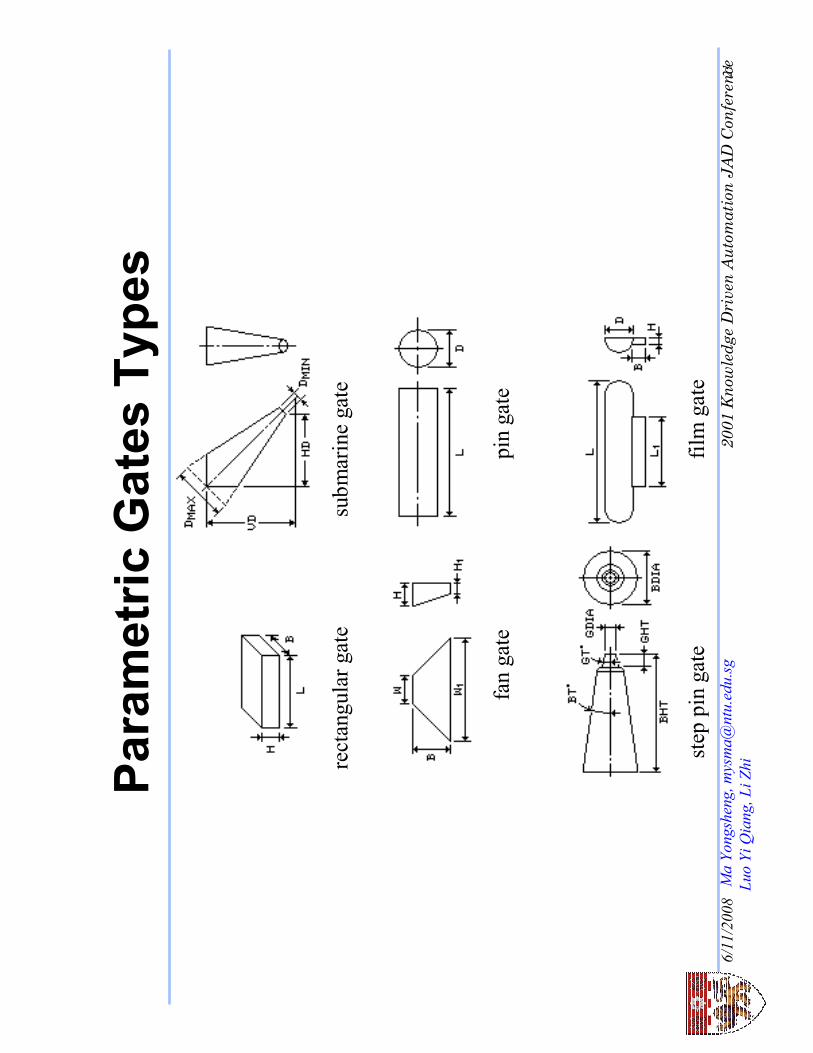
Parametric Gates Types
rectangular gate
submarine gate
fan gate
pin gate
step pin gate
film gate

Select a gate
Select a Gate
Select a gate
Same as
Standard Part
Module
MoldWizard Re-
position Dialog
Fan Gate
Film Gate
Pin Gate
Rectangular
Gate
Step Pin Gate
Submarine Gate
Balance
Unbalance
* If user choose
Balance, all
gates in every
cavities will be
automatically
created at one
time
Gates -Interactions

6/11/2008
2001 Knowledge Driven Automation JAD Conference23
Ma Yongsheng, [email protected]
Luo Yi Qiang, Li Zhi
H-shaped O-shaped S-shaped
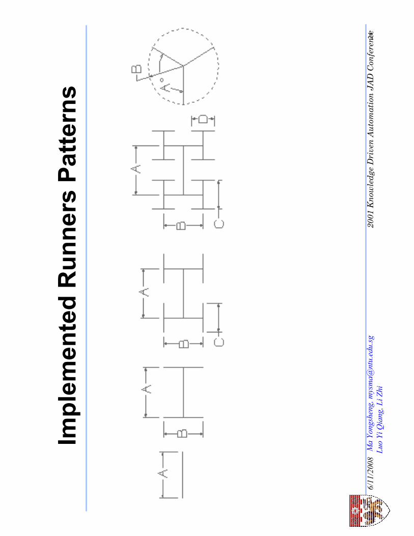
Runners Patterns
C -- Circular,
P -- Parabolic,
T -- Trapezoidal,
H -- Hexagonal, and
S -- Semi-circular.
6/11/2008
2001 Knowledge Driven Automation JAD Conference24
Ma Yongsheng, [email protected]
Luo Yi Qiang, Li Zhi
Implemented Runners Patterns

6/11/2008
2001 Knowledge Driven Automation JAD Conference25
Ma Yongsheng, [email protected]
Luo Yi Qiang, Li Zhi
Runner
•Guide path
projectionto parting
face: Move/copy
/Associate
•Cool well can be
auto-attached
•5 typesof cross
sections available
•Parameterscan
be easily edited

The user can select the
existing curves as guide
strings.

project the planar guide strings
onto parting surface when the
parting surface is not planar.

6/11/2008
2001 Knowledge Driven Automation JAD Conference28
Ma Yongsheng, [email protected]
Luo Yi Qiang, Li Zhi
Electrode -Requirements
• Creating an inverse shape of a portion or the whole of a mold impression
component (i.e. core insert, integer core, cavity insert, integer cavity and
sub-inserts, including certain types of gates)
• Adding a base to the inverse shape (in practice, the base is tightened to a
holder and the latter is fixed to the CNC machine when machining the
electrode as well as the EDM machine when use it to make the
core/cavity)
• Adding a reference coordinate system to the electrode for machining
purposes
• Adding other reference features, such as chamfers, to the base to indicate
the front side so that the electrode is positioned correctly during the EDM
process.

6/11/2008
2001 Knowledge Driven Automation JAD Conference29
Ma Yongsheng, [email protected]
Luo Yi Qiang, Li Zhi Electrode -Definition
Front face of
electrode base
Inverse shape of
electrode block
Face on inverse shape
to be offset to base

6/11/2008
2001 Knowledge Driven Automation JAD Conference30
Ma Yongsheng, [email protected]
Luo Yi Qiang, Li Zhi Electrode -Definition Base
Inverse
shape
Coordinate
system

6/11/2008
2001 Knowledge Driven Automation JAD Conference31
Ma Yongsheng, [email protected]
Luo Yi Qiang, Li Zhi Electrode -Definition
Midpoint of bounding box
for electrode block
Input planar face

6/11/2008
2001 Knowledge Driven Automation JAD Conference32
Ma Yongsheng, [email protected]
Luo Yi Qiang, Li Zhi
Electrode -Assembly Structure
Part for electrode
Wave linked part created from the
working part
Working part

6/11/2008
2001 Knowledge Driven Automation JAD Conference33
Ma Yongsheng, [email protected]
Luo Yi Qiang, Li Zhi
Electrode(Head/Foot)
•Box can be trimmed
by parting face/ sheet/
face
•Box can be created
bybooleanoperation
with other solid
•There is an
association between
foot and head
•Sizes of foot can be
easily adjusted

6/11/2008
2001 Knowledge Driven Automation JAD Conference34
Ma Yongsheng, [email protected]
Luo Yi Qiang, Li Zhi
Sub-Insert -Requirements
The process of creating the entire sub-insert can be divided
into the following tasks:
• creation of sub-insert head
• creation of sub-insert body
• creation of positioning and orientation features
• creation of fastening features
A sub-insert usually has a body to hold the head. In some
cases, however, sub-insert bodies are not created and the
sub-insert head is directly mounted onto a mold plate.
6/11/2008
2001 Knowledge Driven Automation JAD Conference35
Ma Yongsheng, [email protected]
Luo Yi Qiang, Li Zhi
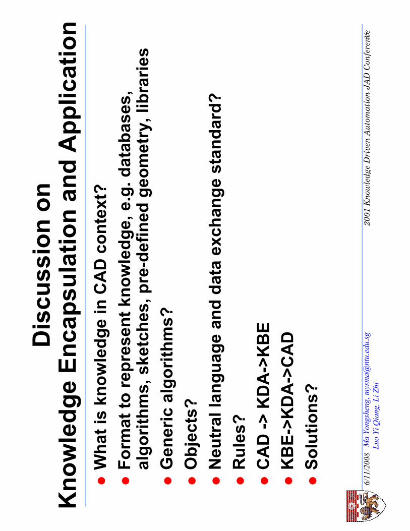
Discussion on
Knowledge Encapsulation and Application
�What is knowledge in CAD context?
�Format to represent knowledge, e.g. databases,
algorithms, sketches, pre-defined geometry, libraries
�Generic algorithms?
�Objects?
�Neutral language and data exchange standard?
�Rules?
�CAD -> KDA->KBE
�KBE->KDA->CAD
�Solutions?

6/11/2008
2001 Knowledge Driven Automation JAD Conference36
Ma Yongsheng, [email protected]
Luo Yi Qiang, Li Zhi
Conclusion
�KDA has great potential
�More research and development is required
�KDA based solutions are highly demanded
�KDA will change the business nature
�KDA globalization
�Knowledge distribution and APS model