Embed Size (px)
Citation preview

ISSN: 2237-0722
Vol. 11 No. 4 (2021)
Received: 14.06.2021 – Accepted: 16.07.2021
3400
Knock based Security Console with Fingerprint Sensor
M.S. Kavitha1; S. Navin Vaishnav2; U. Nikhil Surendar3; R. Mohamed Atheeq4; G.R. Lokgesh5;
E. Santosh6 1Department of Electrical and Electronics Engineering, R.M.K. Engineering College, Chennai, Tamil Nadu,
India. 2Department of Electrical and Electronics Engineering, R.M.K. Engineering College, Chennai, Tamil Nadu,
India. 3Department of Electrical and Electronics Engineering, R.M.K. Engineering College, Chennai, Tamil Nadu,
India. 4Department of Electrical and Electronics Engineering, R.M.K. Engineering College, Chennai, Tamil Nadu,
India. 5Department of Electrical and Electronics Engineering, R.M.K. Engineering College, Chennai, Tamil Nadu,
India. 6Department of Electrical and Electronics Engineering, R.M.K. Engineering College, Chennai, Tamil Nadu,
India.
Abstract
The idea is to fabricate a knock recognizing entryway lock which can distinguish the particular
knocking example and open the entryway if the example is right. This entryway knocking framework
gives a lot of security than other frameworks which are in the market. When there are numerous
clients who utilize the entryway, problems may occur because there is just one key to open the door.
However, here in this entryway locking framework this sort of issues may not happen because the
clients who realize the knocking example can open the door any time without a key. In supplement to
that, knocking framework is joined with finger impression for biometric confirmation which is unique
to every individual and the utilization of unique finger impression as the way to entryway locks can
conquer the security issue of unapproved individuals intruding to our homes, shops, workplaces, and
so on.
Key-words: Fingerprint Sensor, Knocking Framework, Unique Biological Features.
1. Introduction
Bolting and opening entryways are basic errands for the vast majority. Be that as it may, as
detailed by the Department for Work and Pensions, there are enormous number of individuals in
present reality who have skill impedance and need help from others to try and utilize a key.

ISSN: 2237-0722
Vol. 11 No. 4 (2021)
Received: 14.06.2021 – Accepted: 16.07.2021
3401
Further it is reported that there is an increase in robberies occurring in family unit storage
spaces by criminals. Thus, a particular knocking pattern is fabricated with finger print security to get
a protected lock framework with layers of security that can't be broken effectively by gate crashers.
Besides, this sort of lock frameworks can discover its application over the long haul of vehicle
industry as a choice to smart keys that are in presence.
This system can be utilized as follows:
• This gadget expands level of security by adding unique biological features of authorized
individual. For any individual who needs greater security to their homes, it is most ideal
decision.
• A much more extensive use is for individual confirmation, for example to get to a PC, a
network, an ATM machine, a vehicle or a home [10].
• Sparsely populated areas where the risk of being watched is lower could also be a market,
for example having a secret family-knock for the shared holiday cabin.
• The security of the system is phenomenal from a technical perspective. Since the sequence
for opening the door requires both the correct rhythmic and positional pattern, the count of
possible combinations is extremely high.
• Rough estimates show that if just a five-knock pattern yields over 400 million different
combinations – beyond 390 000 times exceeding a five-digit number combination. The lock
can therefore be regarded as impossible to crack with brute force guessing.
• The other uses include user friendliness, Less cost than any locking system, no need to
carry any metal key for this locker, no risk to unlock in any design of knocking pattern,
durability, strong security system.
2. Proposed Methodology
Existing system in the market provides single or simple security system. Most often they are
either simple knock lock systems based on piezoelectric sensor or biometric systems that includes
fingerprint impression detection or face recognition. For an instance, the piezoelectric sensor based
knock lock system can be used only for high frequency signals and requires greater force for
detection due to which the entire door gets locked inevitably under certain circumstances. Also, the
currently available knock lock could be easily unlocked by trial and error method as it contains only
one piezoelectric sensor. In case of finger print security mechanisms such as biometric systems have
quite greater error rate and involves complexity under some special cases. Similarly, voice

ISSN: 2237-0722
Vol. 11 No. 4 (2021)
Received: 14.06.2021 – Accepted: 16.07.2021
3402
recognition security console has also been proven to be one of the least secured systems because of its
ability to broken down easily with the help of voice artists and recorded voice simulators.
Correspondingly, the face recognition method is also a partially secured due to its capability of being
decoded through more or less similar recognizable faces or by displaying the user’s photograph. In an
era where even the smartphones are encoded with highest degree of security, the proposed venture
aims at providing dual layer of security with combined protection of knock and fingerprint pattern.
Figure 1 – Comparison of Different Security Systems
The proposed venture overcomes the security lapses through a modified Knock Based
Security Console using Fingerprint Sensor. The previously existing knock lock system [1] uses
Piezoelectric sensor, Arduino Uno, Hall effect proximity sensor as basic components whereas the
proposed endeavour in this paper is built with 2 vibration sensors placed at particular distances, an
Arduino Nano Microcontroller, R307 Fingerprint sensor, Keyboard and LCD. The combined action
of two vibration sensors at a distance enables the user to create a pin type security based on knock
patterns under a given time delay as coded under.
Arduino. Further, this venture under the control of microcontroller enables the user to put
forward into the next level of security by asking the client to select the fingerprint id from the IDE
source library stored and after this process the user has to verify the fingerprint impression using
R307. The Arduino verifies with the correctness of the knock pattern entered along with the
fingerprint impression received and drives the servo motor to act upon the opening and closing of the
doors thus providing dual layer of security with greater efficiency and hence proves to be safe,

ISSN: 2237-0722
Vol. 11 No. 4 (2021)
Received: 14.06.2021 – Accepted: 16.07.2021
3403
secured than other security consoles existing previously. Working and other processes are further
elaborately discussed under other sections of this journal.
3. Algorithm
The flowchart of the proposed venture is given below:
Figure 2 – Flowchart of the venture
The process flow is elaborated below:
1. Before the real-time use, the user need to enroll their finger impression.
2. End user needs to select the Id and place the finger to store it as a sample in fingerprint
library.
3. User need to store the Knock pattern by various knocking beats over the given two sensor.
4. Once the patterns is stored, now model is ready for testing part.
5. Here the user need to knock the door which would match the already stored (fixed) pattern.
6. If the Given pattern perfectly matches, then the user need to provide the finger impression
on the fingerprint sensor.
7. Else the flow breaks and leads to stop.
8. If the flow is uninterrupted it further checks with the already stored finger impressions from
the library.

ISSN: 2237-0722
Vol. 11 No. 4 (2021)
Received: 14.06.2021 – Accepted: 16.07.2021
3404
9. The above condition matches then the door might open with the welcome message on LCD
screen otherwise it won't.
10. The flow reaches stop.
4. Architecture of the Model
The square chart of the proposed model is given below:
Figure 3 – Block Diagram
A. Components
The components used in this model are:
• Arduino Nano
• Servo Motor
• Vibration Sensors
• Fingerprint Sensor
• Keyboard
• LCD
B. Design
The design of the endeavor includes a key unit Arduino Nano which is a viable, adaptable and
breadboard well disposed Microcontroller board, created by Arduino.cc, in view of ATmega328p
(Arduino Nano V3.x)/Atmega168 (Arduino Nano V3.x). It accompanies identical usefulness as in

ISSN: 2237-0722
Vol. 11 No. 4 (2021)
Received: 14.06.2021 – Accepted: 16.07.2021
3405
Arduino UNO yet very in little size. It is associated with any remaining segments like different
sensors and servo engine.
The ideal angle of the servo is determined by taking care of it electrical beats of a predefined
length and recurrence on its control line. The other two pins on the servo's three-pin connector are for
a 4.5-6.0V power source and ground to drive the engine and its installed circuit. The control hardware
inside devours almost no current and can be stopped straightforwardly to an Arduino's I/O pin.
Servos are compelled by sending electrical beats of variable width, or PWM, through the
control wire. There is a base pulse, an extreme pulse, and an emphasis pulse. A servo motor can
commonly turn 90° on one side without a moment's delay, for a total of 180° revolution.
The system is best suited for 90° on left side because it provides quick opening and closing
action. Moreover it provides high efficiency with more constant torque at higher speed. Small size
structure provides smooth and quiet operations. It is well suited for door applications. This servo
motor receives combined signals from vibration sensors and finger print sensors through Arduino.
The working standard of vibration sensor is a sensor which works dependent on various
optical otherwise mechanical standards for identifying noticed system vibrations.
This model has two vibration sensors. The sensor uses LM393 comparator to recognize the
vibration over a threshold point and provide digital data-Logic High or 1. During knocking operation
on sensor1, the sensor1 goes high provides Logic high when the vibration is detected. Similarly, the
sensor 2 also works on this principle. Most often the knocking pattern is interlaced and array of
pattern is stored during recording and checking time [1].
Figure 4 – Array of Knock Pattern
Further the process is followed by finger print sensor where unique finger impression
handling incorporates two sections: finger impression enlistment and finger impression verifying (the
verification can be 1:1 or 1:N). While enlisting, client needs to enter the finger two times. The

ISSN: 2237-0722
Vol. 11 No. 4 (2021)
Received: 14.06.2021 – Accepted: 16.07.2021
3406
framework will deal with the double cross finger pictures, produce a format of the finger dependent
on handling results and store the layout. While verifying, client places the finger on optical sensor
and framework will produce the received finger pattern and compare it with formats of the finger
prints present in the library. Accordingly, the framework will display the coordinating outcome, true
or false.
This model includes 1:N coordinating for providing multiple access through door. It provides
high security and assurance in a convenient and faster way. These unique templates or id are
non-transferrable and are hard to fake or steal [8].
The above mentioned processes are accompanied by a unique component known as
‘Keyboard’. A keyboard typically contains keys for specific functions. The key which are referred
here are push buttons. The push button is a segment that associates two ends in a circuit when it is
pressed.
At the point when the push button is released, there is nothing associated between the two
ends of the push button, so the pin is associated with 5 volts and gives a HIGH (1) output. At the
point when the catch is shut (squeezed), it makes an association between its two ends, interfacing the
pin to the ground, with the goal of getting a LOW (0) output.
This model consists of 5 push buttons:
• Increase Id
• Decrease Id
• Enrollment
• Record
• Verification
Increase Id Button - It helps to move upwards across the user-Id.
Decrease Id Button - It helps to move downwards along the user-id
Enrollment Button - It helps to enroll the finger print templates for a unique selected Id.
Record Button - It helps to record/set or to alter the knocking patterns in the model.
Verification Button - It helps to verify the input details with the already stored data and
provides necessary data for alteration.
The end users are kept informed with the help of a LCD. This display has an inbuilt character
generator RAM, the client can modify character designs through programming code. For 5 x 8
specks, eight character examples can be composed, and for 5 x 10 spots, four character examples can
be composed. It is used to show the coordinating result of framework as True or False and other
information.

ISSN: 2237-0722
Vol. 11 No. 4 (2021)
Received: 14.06.2021 – Accepted: 16.07.2021
3407
B. Software Implemented
The Arduino Integrated Development Environment is an open source application that is used
to write in languages like c,c# or other embedded languages. The software version that has been used
to encode the functionalties into microcontroller is V1.8.13. It has an editor for typing the code and a
compiler enabled in it. The Arduino IDE has various alternatives in toolbar accommodated different
enhacement activites of the client text editor, complier, debugger etc. The ide environment is quite
reliable because of its simple and easy to use purpose. The code is then uploaded into the Arduino
module via USB cable. They generally support c , c# and c++ languages.
The features include various types of libraries are provided for coding purposes which makes
it easy to perform, more number of editing tools from menubar. It supports almost every aurdino
boards. The sketch section provides the user to run, compile, fix, upload the code, include library and
add file. The output panel gives the comments/remarks for any error occurred or successfully
uploaded.
5. Operation
After turning ON the supply and connecting the model with USB cables, the model is ready to
use. It works in two modes
1. Enrolment Mode
2. Testing Mode
A. Enrollment Mode
It is a fundamental arrangement required to run the model successfully. The following are the
procedures to be done in Enrollment Mode:
i. The specific id has to be chosen with the assistance of increasing/decreasing push button.
ii. Press enrol push button and save the finger impression template twice on fingerprint-sensor for
that id.
iii. Further, moving to recording push button, the end user can record the pattern with given two
vibration sensor.
iv. The array of the pattern is stored.
v. It is ready for testing.
ISSN: 2237-0722
Vol. 11 No. 4 (2021)
Received: 14.06.2021 – Accepted: 16.07.2021
3408
B. Testing Mode
The Testing Mode is a user friendly mode and following are the procedures involved:
i. The user has to match with correct pattern by entering the correct mixture of thumping with the
given two sensor.
ii. After that, the client is asked keep the finger impression on the fingerprint-sensor.
iii. The template will compare it given templates in library.
iv. If all the above function satisfies the condition then the servomotor will be turned ON.
v. Door gets opened and particular Id is displayed.
vi. The full working is accompanied with the assistance of LCD screen instruction.
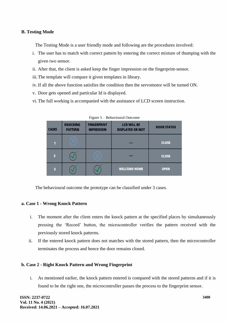
Figure 5 – Behavioural Outcome
The behavioural outcome the prototype can be classified under 3 cases.
a. Case 1 - Wrong Knock Pattern
i. The moment after the client enters the knock pattern at the specified places by simultaneously
pressing the ‘Record’ button, the microcontroller verifies the pattern received with the
previously stored knock patterns.
ii. If the entered knock pattern does not matches with the stored pattern, then the microcontroller
terminates the process and hence the door remains closed.
b. Case 2 - Right Knock Pattern and Wrong Fingerprint
i. As mentioned earlier, the knock pattern entered is compared with the stored patterns and if it is
found to be the right one, the microcontroller passes the process to the fingerprint sensor.

ISSN: 2237-0722
Vol. 11 No. 4 (2021)
Received: 14.06.2021 – Accepted: 16.07.2021
3409
ii. Meanwhile, the LCD prompts the user to select the specific fingerprint id from the IDE libraries
so that the fingerprint impression is verified.
iii. If the entered impression does not matches with the impression linked with corresponding IDE,
then the LCD shows ‘Invalid id’ and hence as a result the servo motor remains still indicating a
locked door.
c. Case 3 - Right Knock Pattern and Right Fingerprint
i. In this case, the knock pattern is compared by microcontroller with available patterns and if it is
found to be the ideal one, process is accompanied by fingerprint scanning.
ii. Correspondingly, the user selects the respective id through the LCD and is checked for
fingerprint verification.
iii. If the received fingerprint impression matches with the corresponding id present in the IDE,
then the LCD prompts ‘Welcome’ and also the Arduino Nano commands the servo to rotate to
its adjacent 90 degrees from its initial position, thus, opening the door.
Figure 6 – Prototype of the System
6. Results
The opening and locking of the entryway lock worked reliably with proper guidance of LCD.
The combined action of knocking pattern along with the finger print sensor turned out to be one of
the most secured, low cost, user friendly locking system that has been made. An overall observation
with respect to knock detection was that wide, more sound-proof doors resulted in less dependable
sensor readings than thinner doors.

ISSN: 2237-0722
Vol. 11 No. 4 (2021)
Received: 14.06.2021 – Accepted: 16.07.2021
3410
7. Future Scope
In this paper, the worry of security is being tended to through effectively and reasonable
innovation like vibration sensor, unique finger impression sensor, Push buttons, and Arduino
microcontroller with LCD show.
Few of the future scopes of the proposed model are:
• This model can be extended to other forms of security methods through Iot.
• This endeavor can be improved by interfacing with various advancements like face
recognizable proof, voice acknowledgment, etc., as such making it significantly safer while
not being too excessive and distant in regards to openness.
• The proposed model consists of two vibration sensors at specified places. These sensors’
position can be varied as needed by the user so that unknown access could be limited.
• The number of vibration sensors being used can be increased on the long run based on the
required complexity.
• Increasing the number of vibration sensors at specified distances in the venture can enable a
stronger pattern of knocks such that it generates a more complex pin like security that
couldn’t be breached.
• Future implementation of this venture can be extended to provide security system in cars.
• The compact size of the model can be utilized to make a secured locker units for household
usage.
8. Conclusion
In this age of trend setting innovation, robbery and wrongdoing has taken the guide of
innovation itself in accomplishing its outcomes ordinarily. To stay away from such conditions, now
and again even little things can provoke an incredible change. Hence, execution of savvy devices in
Security Control like the Knock Based Security System with unique finger impression sensor can end
up being entirely important to the individual utilizing it and moreover to the actual resources.
References
“Security System based on Knock-Pattern Using Arduino and GSM Communication”, R. Sai Charan
Reddy, P.Vamsi Krishna, M.Krishna Chaitanya, M.Neeharika, K Prabhakara Rao.
Rupinder Singh Brar, “ARDUINO Based Industrial Security System using Piezo-Electric Sensor”

ISSN: 2237-0722
Vol. 11 No. 4 (2021)
Received: 14.06.2021 – Accepted: 16.07.2021
3411
“Sensor based home automation and security System”. Instrumentation and Measurement
Technology Conference (I2MTC), 2012 IEEE International.
“SmaCk: Smart Knock Security Drawer Based on Knock-Pattern using Piezo-electric Effect”, Alvin
S. Alon, Cherry D. Casuat, Mon Arjay F. Malbog, Jennalyn N. Mindoro.
H. Huang, S. Xiao, X. Meng, and Y. Xiong. “A Remote Home Security System Based on Wireless
Sensor Network and GSM Technology”. Proc. On 2010 2nd International Conference on Network
Security, Wireless Communications and Trusted Computing, 1, 535-538, April 2010.
D. Narmada and J.V. Priyadarsini, “Design and implementation of security based ATM using
ARM11”, 2016 International Conference on Inventive Computation Technologies (ICICT),
Coimbatore, 2016, 1-4. Kumar.
M.H. Assaf, R. Mootoo, S.R. Das, E.M. Petriu, V. Groza, S. Biswas. “Sensor Based Home
Automation and Security System”. 2012 IEEE International Instrumentation and Measurement
Technology Conference (I2MTC 2012) Proc., Year 2012.
“Door Unlocking System using Fingerprint Sensor for Home Automation”, Ganesh Sahithi Murru,
Chetan Kakollu, Ashok Kumar Kenguva, P. Surya Chandra.
Ashwini, S. Delfin, N.Harinadh. “Smart Fire Alarm System Using Arduino”. International Journal of
Emerging Technologies in Engineering Research (IJETER), 7(5), May (2019).
N. Bharath Kumar, “Anti-Theft ATM Machine Using Vibration Detection Sensor”.
K. Rubini, M. Vidya, S.R. Yeshaswini, A. Gowthami. “Automatic Ambulance Detection and
Intimation Using RSSI”. International Journal of Emerging Technologies in Engineering Research
(IJETER), 7(3), March (2019)
S. Solanke, N. Sonawane,V. Ugale, S.A. Khoje.” Home Security Using Image Processing and IOT”.
International Journal of Emerging Technologies in Engineering Research (IJETER), 5(6), 2017.
“Working principle of an Arduino”, Abuja, Electronics Computer and Computation (ICECCO):11th
international conference IEEE.
R.C. Wang, W.S. Juang and C.L. Lei, “User authentication scheme with privacy preservation for
multi-server environment”, IEEE Communication Letters, 13, 157-159, 2014.
Jeremy Blum. “Exploring Arduino: Tools and Techniques for Engineering Wizardry”, Wiley
publishers, 4th edition (2004).
P. Mercy Angelina, T.M. Sirisha. “Large scale Contextual recommended systems of online
learning”.
Juels, “ RFID security and privacy: A research survey”, IEEE Journal on chosen areas in Computing,
24(2): 381–394, 2006.
T.B. Zahariadis and A.K. Sakintzis, “Introduction to special feature on wireless home network”,
ACM Mobile Computing and Communication Review, 7(2), 2013.
W. Durfee, “Arduino Microcontroller Guide”, University of Minnesota, Ver-2014.
Nikhil Agarwal, “Microcontroller based home security system with remote monitoring”, Department
of EC engineering, MIT, Manipal.
M. Faundez Zany, “On the vulnerability of biometric security system”, IEEE aerospace and
electronic system magazine, 2014.

ISSN: 2237-0722
Vol. 11 No. 4 (2021)
Received: 14.06.2021 – Accepted: 16.07.2021
3412
Theodre, S.Rappaport, “Wireless Communications”, Second Edition PHI, New Delhi.
“Introduction to Arduino,a piece of cake”, Alan G Smith, September 30 2011.
“Arduino Micro-controller Guide, W.Durfee”, University of Minnesota, Ver-2011.
Baik, S.H., Chun, K.M. “A study on the transient knock control in a spark-ignition engine”. SAE
paper 981062, 1998.
L. O’Gorman “Comparing passwords, tokens and biometrics for user authentication”. Proceedings of
the IEEE, 91(12), 2021-2040, 2003.
M. Faundez-Zanuy “Biometric recognition: why not massively adopted yet?”. IEEE Aerospace and
Electronic Systems Magazine. 20(8), 25-28, 2005.
M. Faundez-Zanuy “Privacy issues on biometric systems”. IEEE Aerospace and Electronic Systems
Magazine. 20(2), 13-15, February 2005.
A.J. Mansfield, J.L. Wayman, “Best Practices in Testing and Reporting Performance of Biometric
Devices”. Version 2.01. National Physical Laboratory Report CMSC 14/02. August 2002.
M. Faundez-Zanuy “Door-opening system using a low-cost fingerprint scanner and a PC”. IEEE
Aerospace and Electronic Systems Magazine. 19(8), 23-26. August 2004
M. Faundez-Zanuy, & Joan Fabregas “Testing report of a fingerprint-based door-opening system”.
IEEE Aerospace and Electronic Systems Magazine, 20(6), 18-20, 2005.
D. Maltoni, D. Maio, A.K. Jain, S. Prabhakar “Handbook of Fingerprint Recognition” Springer
professional computing. 2003.
E. Fernandes, J. Jung, and A. Prakash, “Security analysis of emerging smart home applications,” in
2016 IEEE Symposium on Security and Privacy (SP), 2016, 636–654.
G. Gautschi, “Piezoelectric sensors,” in Piezoelectric Sensorics. Springer, 2002.
C.F. Scola and M.D.B. Ortega, “Direction of arrival estimation: A two microphones approach,”
2010.