Embed Size (px)
Citation preview

KNEE EXOSKELETON “Your walk assistant”
A.Y. 2013/2014, Mechanical Engineering
CAD Lab
Alessandro Saccomani
Jinou Xu
Aldo Sestito

Politecnico di Milano Alessandro Saccomani
Mechanical Engineering Jinou Xu
A.Y.:2013-2014 Aldo Sestito
1
1. Introduction
2. General Problem
3. Our Solution
4. Four-Bar System
5. Motor Implementation
6. Other Features
7. FEM Analysis
8. Exploded view

Politecnico di Milano Alessandro Saccomani
Mechanical Engineering Jinou Xu
A.Y.:2013-2014 Aldo Sestito
2
1. Introduction
This project is based on a proposal suggested by the company Roadrunnerfoot, which was looking for a mechanism able to help people with disability. In particular, their aim was to
create a prototype of an active knee brace, that could assist those people who suffer a partial or total impossibility of knee motion.
In the following pages we will describe in details how the system represented in the picture is
made and works.

Politecnico di Milano Alessandro Saccomani
Mechanical Engineering Jinou Xu
A.Y.:2013-2014 Aldo Sestito
3
2. General problem We focused on the real behavior of the knee movement in order to achieve a system which was able to follow the motion of the knee without forcing the ligaments with a not natural
kinematic.
In fact, after some researches, we found that the knee doesn’t just rotate around a fixed point as it’s easy to imagine watching it from the outside, but behaves as a 4 bar linkage, which of course is much more complex. That was the first problem we faced once we decide to model the knee according to this theory, but not the only one because it was also rather complex to decide which was the best way to induct the motion of this 4 bar system, considering that in a 2D scheme it’s just a one degree of freedom system like this:
We didn’t want only to respect as more as possible this physiological constrain, but we also wanted to satisfy some other extra aims:
-Lightness of the whole system;
-Comfortable wearing;
-Safety design;
-Innovative solution;
-Adaptability;
In order to achieve this results, we have done some design choices we’ll describe later.

Politecnico di Milano Alessandro Saccomani
Mechanical Engineering Jinou Xu
A.Y.:2013-2014 Aldo Sestito
4
3. Our solution
This is a general view of what we have done.
The exoskeleton is composed by two main supports (lower one and upper one), which are fixed on the leg by means of velcro closures that tighten themselves over a soft rubber part
(the black partial circular offset). The two supports are linked together with a four-bars system, that provides a path which follows the knee motion. The four-bars mechanism is protected
inside a transparent box for safety reasons.
The power is provided by a linear actuator (which works like the mechanism of the crane) that converts a linear motion into a roto-translational one.
On the lower part there is a system which allows the customer to change the length of the support to better suit to the leg. The pedal was added with a rotational joint to allow the ankle
to rotate, since we have verified on internet that the ankle just rotates around a joint. It’s also useful to discharge the forces to the ground.
Between the leg and the exoskeleton there is the already cited soft part which provides
comfort and avoid dry friction between the parts that has to be connected.

Politecnico di Milano Alessandro Saccomani
Mechanical Engineering Jinou Xu
A.Y.:2013-2014 Aldo Sestito
5
4. Four-bar System Now we have to justify properly our choices.
The idea of the four-bar system was taken from a thesis on the mechanism simulating the knee
motion (The link is one the website).
As we can see, that study was focused on the inner knee substation, but we thought that it was
possible to apply such a mechanism also on an external support for people who still have legs,
but aren’t able to move it. In fact, we observed that many companies dealing with this problem
never use the 4 bars system.
By a mechanical point of view, the 4 bar system is not complicated, but it was really difficult to
understand the dimensions that should be used in order to not stress too much the knee. It’s
important to understand that into a real knee, the yellow and the grey bars (represented in the
next page) have no constant lengths, but can elongates depending on the position of the leg.
So it’s an approximation. But we found some useful information on some books that provides
us some values of dimensions of similar mechanisms that can be accepted (and of course that
are already in use).
The result is the following:

Politecnico di Milano Alessandro Saccomani
Mechanical Engineering Jinou Xu
A.Y.:2013-2014 Aldo Sestito
6
As it’s easy to see, we use 4 bearings into the 4 rotational joints. The mechanical properties of
those part can be checked on this table (it’s the number 608):
Over these values, we have built the bars and their holes adapt to these dimensions.

Politecnico di Milano Alessandro Saccomani
Mechanical Engineering Jinou Xu
A.Y.:2013-2014 Aldo Sestito
7
5. Motor implementation
A following design feature that was difficult to deal with was to find some motor that was able to generate a large force without being too heavy and big (and so hard to support). Strictly
related to that, it was the problem of selecting the best kind of motion to apply: rotation or translation, since we had to convert it into the roto-translation of the knee.
Our main inspiration was the mechanism of the crane, with a linear actuator that, attached to
the upper bar, was able to induct a linear motion to the lower bar that converts it to the motion we were looking for.
The linear actuator is fixed on the two supports with a rotational joint, thanks to the welded small cylinder which as a change in radius that locks the holed part of the piston.
The mechanism works exactly like the crane. The only difference is that the crane just activate a
rotation, while in our case the actuator provides the degree of freedom that allow the motion of the four bar system.
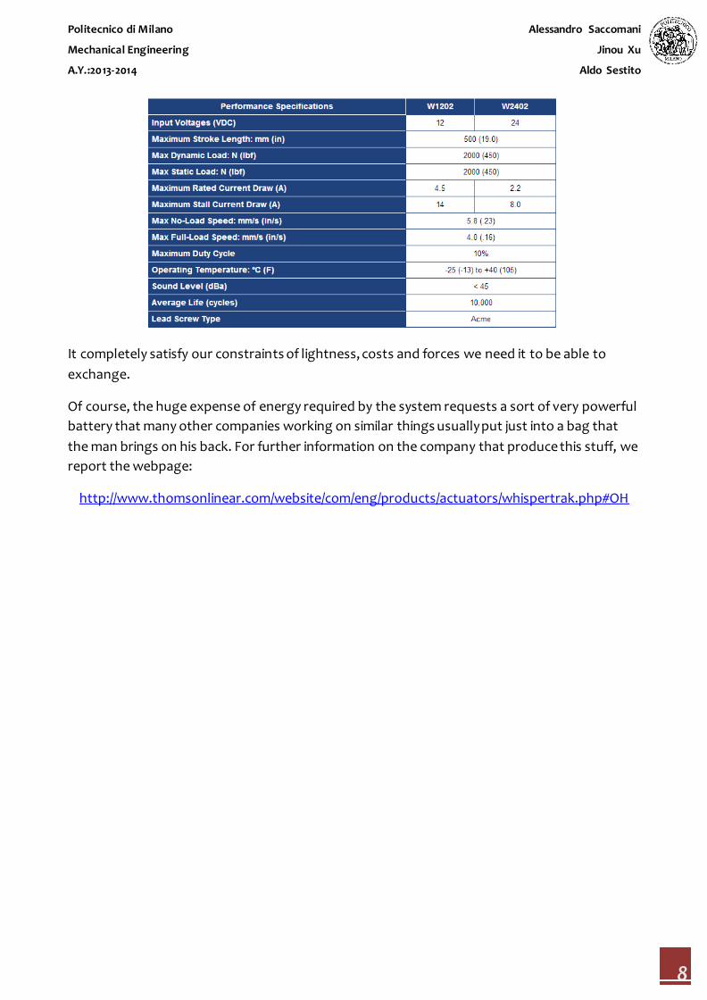
The tool we have chosen is this one, with all the specifics reported in the tab in the next page:
Politecnico di Milano Alessandro Saccomani
Mechanical Engineering Jinou Xu
A.Y.:2013-2014 Aldo Sestito
8
It completely satisfy our constraints of lightness, costs and forces we need it to be able to
exchange.
Of course, the huge expense of energy required by the system requests a sort of very powerful
battery that many other companies working on similar things usually put just into a bag that
the man brings on his back. For further information on the company that produce this stuff, we
report the webpage:
http://www.thomsonlinear.com/website/com/eng/products/actuators/whispertrak.php#OH

Politecnico di Milano Alessandro Saccomani
Mechanical Engineering Jinou Xu
A.Y.:2013-2014 Aldo Sestito
9
6. Other features ADJUSTABLE LENGTH
SELF LOCKING ANGLE
In order to adapt the device to
different people, we thought to
model this simple mechanism that
allows people to change the
length of the lower bar.
The maximum and the
minimum angles of rotation are
just fixed when the run is over.
It’s important also because the
length of the piston is limited.

Politecnico di Milano Alessandro Saccomani
Mechanical Engineering Jinou Xu
A.Y.:2013-2014 Aldo Sestito
10
PROTECTING LAYER
PROTECTING BOX
Between the bars and the leg, we
just added a layer that divides the
mechanism and the anatomical
parts. Moreover, a soft part after
the layer is inserted to gain
comfort.
It’s simply a stuff used to contain
the 4 bars system. By a practical
point of view, it’s useful to avoid
that the mechanism pinches
someone or something.

Politecnico di Milano Alessandro Saccomani
Mechanical Engineering Jinou Xu
A.Y.:2013-2014 Aldo Sestito
11
7. FEM analysis Now it’s rather important to see the effects of the force generated on the whole system by the
actuator making a proper FEM analysis and see if the values of the stress, strain and
displacement are acceptable. We suppose an exchanged force of 500 Newton (more than 50
kilos for each leg, that is a correct value if we consider a person that doesn’t exceed the 90 kg
of weight) that discharges on the bars. In particular it’s applied exactly where the actuator is
mounted. It was also important to use a material which was not too heavy and expensive. We
were lucky because we realized, after a very first FEM analysis, that the common alloy steel was
suitable for our intent. Moreover, the total weight of the system does not exceed 4.5 kg (for
each leg), so our aim of lightness is satisfied. To perform the analysis, of course we need to
impose the constrains, that are slider constrains and rotational ones. We also added the
presence of gravity.
Below the graphs of the analysis made with the software SolidWorks are reported.
NB: the mesh is automatically done by the software.
UPPER BAR
The maximum stress on the upper
bar in much lower than the Yield
strength of the selected material,
so we don’t have to worry for
problem regarding the elasticity of
the tool.

Politecnico di Milano Alessandro Saccomani
Mechanical Engineering Jinou Xu
A.Y.:2013-2014 Aldo Sestito
12
LOWER BAR
Also the values of the strain are
acceptable…
…and the maximum displacement
is in the order of the tenth of
millimeter, which is of course
acceptable for a system of that
kind (exactly 0.9 mm).
Similar reasoning can be done for
the stress of the lower support,
getting the same result as before:
to not overcome the yield
strength.

Politecnico di Milano Alessandro Saccomani
Mechanical Engineering Jinou Xu
A.Y.:2013-2014 Aldo Sestito
13
We can conclude that, from the structural point of view, we have no particular problems with
our system.
No problems at all were found in
the analysis of the strain and of the
displacements (max value of 0.4
mm) also for the lower part.

Politecnico di Milano Alessandro Saccomani
Mechanical Engineering Jinou Xu
A.Y.:2013-2014 Aldo Sestito
14
8. Exploded view


![A Molecular Cage-Based [2]Rotaxane That Behaves as a ...ntur.lib.ntu.edu.tw/bitstream/246246/169681/1/499.pdf · A Molecular Cage-Based [2]Rotaxane That Behaves as a Molecular Muscle](https://img.dokumen.tips/doc/110x75/5b24c0b47f8b9a3b0f8b519a/a-molecular-cage-based-2rotaxane-that-behaves-as-a-nturlibntuedutwbitstream2462461696811499pdf.jpg)