Embed Size (px)
Citation preview
KLINGER®top-sil-ML1Revolutionary combination of synthetic fibres
and different elastomers bound in a Multi-Layer* structure.
* Patent pending
KLINGER – The global leader in static sealing
®
KLINGER top-sil-ML1Unique Multi-Layer*
material concept – A milestone
for fibre reinforced gaskets

HNBR Matrix✽ Long-term flexible layer✽ High thermal stability✽ Reduced brittleness
✽ Oxidation and ageing resistant✽ Optimised curing system
NBR Matrix✽ High network density✽ Low creep under load
✽ High strength✽ High permissible load
The layers of the structure are characterised by the selection of elastomers. Since at least one of the layers contains a different elastomer (compared with the standard elastomers like NBR, SBR, etc.) the decomposition and ageing processes associated with conventional fibre materials i.e. post curing, thermo oxidative decomposition, degradation of the polymer chains etc. depending on application, can be suppressed.
The Multi-Layer structure makes it possible to develop materials with new property profiles. The layers containing the special elastomers remain flexible over longer periodes than standard materials even at high temperatures and are therefore able to compensate for dynamic load fluctuations induced by the flange. This flexibility suppresses the creation of micro crevices, which are responsible for gasket leakage.
The layers containing standard elastomers are better able to resist deformation under load due to the formation of a denser network.
The gasket therefore remains flexible but still retains its strength.
* Detailed information aboutthe Multi-Layer
concept can be supplied separately
on request.
For quite some years the sealing industry in general has been un-able to offer an adequate substitute for the KLINGERit gasket. This gasket, because of its absence of embrittlement at high tempera-tures was extremely successful.
We are pleased to advise that exactly 110 years after the inven-tion of KLINGERit, KLINGER is able to re-confirm its leading posi-tion in the field of fibre reinforced gaskets with the latest development
KLINGER®top-sil-ML1.
This new concept in material technology* ties up with the performance benchmark set by KLINGERit gaskets.
Multi-Layer property profile ✽ Extended service life and
less leakage in spite of high temperatures
✽ Higher residual flexibility ✽ Delayed ageing✽ Less creep✽ High permissible load
®
KLINGER top-sil-ML1Unique Multi-Layer material concept

Tightness behaviour in saturated steamThis test is an excellent method to test the decomposition of elastomer bounded sealing materials within a reasonable time. The applied temperature of 320°C coupled with an environment of saturated steam at around 120 bar provides a stringent test for the elastomers. The arduous nature of the test con-ditions is designed to promote de-composition of the samples, allowing an assessement of ageing resistance of the Multi-Layer materials.By these extrem testing conditions a differentiation of different gasket types becomes possible.
A sudden pressure loss within the test rig chamber indicates either steam escape through crevices within the material or destruction of the test specimen. Both effects result from embrittlement of the gasket due to degradation of the elastomers.
The time before the pressure drop occurs can be seen as a measurement of the ageing resistance of the gasket. In order to quantify the effects caused by the formationof micro crevices, the test rig was pressurised with 40 bar nitrogen to measure the leakage rate at room temperature following the steam test. By this method a direct correlation can be defined between the ageing of the gasket and its leakage rate.
The Multi-Layer material guarantees the user significantly lower emissions over a longer service life at elevated temperatures.
Tightness
behaviour in
saturated
steam
Elastic propertiesTo evaluate flexibility potentials of sealing materials the three point bending test is often used to assess the flexibility of compressed fibre materials. Trials with conditioned test specimens provide an indication of the level of embrittlement and therefore the ageing behaviour of the elastomers employed.
Prior to the bending tests samples were conditioned as follows.
✽ Hot air for 168 h at 160°C and ✽ Saturated steam for 168 h
at 185°C
Steam hammer often occurs in steam applications and leads to damage of the sealing materials. A more flexible gasket will therefore contribute to a safer and more reliable flange connection.
The novel Multi-Layer material concept significantly increases ageing resistance at elevated temperature when compared with conventional materials.
With this concept, it is possible to minimise all the undesirable property changes associated with traditional compressed fibre materials such as embrittlement, formation of crevices and increased leakage.
Incorporation of special elastomers into separate layers within the Multi-Layer structure ensures that a longer service life and increased temperature resistance can be expected.
Tests have shown that such a combination of properties cannot be achieved through homogenuous mixing of two elastomers.
Elastic
properties
KLINGER top-sil-ML1 A milestone for fibre reinforced gaskets
®
NBR Multi-Layer
high
er fl
exib
ility
Elongation %
Ben
ding
str
engt
h
NBR Multi-Layer
Time d
Inte
rnal
pre
ssur
e
extended service life

ppp i
i a 0
r30
40
50
60
70
80
90
11100
The many, varied demands placed on gasketsA common perception is that the suitability of a gasket for any given application depends upon the maximum temperature and pressure conditions. This is not the case.
Maximum temperature and pressure values alone can not define a material’s suitability for an application. These limits are dependent upon a multiplicity of factors as shown in the diagram opposite. It is always advisable to consider these factors when selecting a material for a given application.
*Gaskets according to DIN 2690 areonly standardised up to PN 40 andgasket thickness 2 mm.
Selecting gaskets with pT diagramsThe Klinger pT diagram provides guidelines for determining the suitability of a particular gasket material for a specific application based on the operating temperature and pressure only.
Additional stresses such as fluctuating load may significantly affect the suitability of a gasket in the application and must be considered separately. Always refer to the chemical resistance of the gasket to the fluid.
In area one, the gasket material is normally suitable subject to chemical compatibility.
In area two, the gasket DIN 2690/ DIN EN 1514-1 form IBC up to PN 40*mat
erials may be suitable but a technical evaluation is recommended.
In area three, do not install the gasket without a technical evaluation.
Areas of Application
Klinger Hot and Cold Compression Test Method The Klinger Hot Compression Test was developed by Klinger as a method to test the load bearing capabilities of gasket materials under hot and cold conditions.
In contrast to the BS 7531 and DIN 52913 tests, the Klinger Compression test maintains a constant gasket stress throughout the entire test. This subjects the gasket to more severe conditions.
Temperatures up to 300°C are then applied and the additional thickness decrease is measured.This simulates the first start up phase.
The thickness decrease is measured at an ambient tempe-rature of 23°C after applying the gasket load.This simulates assembly.
The diagram shows additional thickness decrease at temperature
6080100
2040
010
20
30
40
50
60
70
0 20
0
Stress MPa
10
20
30
40
50
60
70
Thic
knes
s de
crea
se %
Thic
knes
s de
crea
se %
®
KLINGER top-sil-ML1
20
10
-200 - 150 -100 -50 0 50 100 150 200 250 300 350
40 60 80 100 120

®
KLINGER top-sil-ML1 Flanged joint integrity
Maximum permissible surfacepressure σBO under operating
conditions acc. DIN 28090 – 1 The maximum surface pressure under operating conditions is the maximum allowable surface pressure on the effective gasket area under service conditions that can be applied to the gasket before unacceptable relaxation of the flanged joint occurs and/or the gaskets are destroyed.
The diagram above shows this values for different gasket thicknesses.
Min. surface pressure σVU
for tightness classes L = 1.0, L = 0.1 and L = 0.01 in accordance to DIN 28090The minimum surface pressure is the minimum surface pressure that should be applied to the gasket to achieve the necessary tightness requirements.
The value must be sufficient to compress the material into the flange imperfections, reduce the materials porosity and also counteract the release of load due to the internal pressure.
The diagrams below show the minimum gasket stress required to achieve the relevant tightness classes as a function of thickness.
0
20
50
40
30
60
90
1100
10 20 30 40 50
1.0 mm
1.5 mm
2.0 mm
3.0 00mm
0
20
50
40
30
60
90
1100
10 20 30 40 50
1.0 mm
1.5 mm
2.0 mm
3.0 00mm
0
20
50
40
30
60
90
1100
10 20 30 50
1.0 mm
1.5 mm
2.0 mm
3.0 00mm
0
100
250
200
150
350
300
450
400
500
50
0
100 200 300 400
3.0 mm
Tightness class L= 0.1 allows a maximum leakage of
0.1 mg nitrogen per second per meter of gasket length (mg/s x m)
Modulus of elasticity ED in accordance to DIN 28090This diagram outlines the modulus of elasticity compared to the surface load. The curves describe the behaviour at ambient temperature and at 150°C.

®
KLINGER top-sil-ML1 Flanged joint integrity
Important points to be observed With heightened awareness of safety and environmental issues, reducing leaks from flanged assemblies has become a major priority for industry. It is therefore important for com-panies who use gaskets to choose the correct material for the job and install and maintain it correctly to ensure optimum performance.
A flanged joint will remain tight as long as the surface pressure in service is higher than the minimum surface pressure required to achieve the necessary levels of tightness but is lower than the maximum permissible surface pressure. But increasingly high demands on the tightness requirements for flanged joints (e.g. Tightness class L 0.1 in accordance with DIN 28090) necessitate the application of high loads on the gasket material in order to meet these stringent requirements.
If the gasket is to be subjected to non-static loading and stress fluctuations due to temperature and pressure cycling, it is advisable to select a gasket material which is less prone to embrittlement with increasing temperatures (e.g. KLINGERgraphite laminate, KLINGERtop-chem or KLINGERtop-sil). In cyclic loading conditions we recommend a minimum surface stress of 30 MPa and that the gasket should be as thin as is practicable.
For safety reasons never re-use gaskets.
Gasket load
10 MPa
Gasket load
20 MPa
Gasket load
30 MPa
1.0
0.1
5020
100
4060
80
100 150 200 250 300
00
Temperature °C Gas pressure bar
Leak
mg/
(sm
)
Leak
mg/
(sm
)1.0
0.1
1.0
0.1
5020
100
4060
80
100 150 200 250 300
00
Temperature °C Gas pressure bar
Leak
mg/
(sm
)
Leak
mg/
(sm
)
1.0
0.1
1.0
0.1
5020
100
4060
80
100 150 200 250 300
00
Temperature °C Gas pressure bar
Leak
mg/
(sm
)
Leak
mg/
(sm
)
1.0
0.1
High temperature tightnessHigh temperature tightness is measured by means of the Klinger Hot Compression test under defined constant gasket load and temperature with increasing internal pressures using nitrogen as test fluid.
Stabilisation time for each reading is two hours and a new test specimen is used for every gasket load and temperature.
The tightness is analysed with a massflow meter. The pressure is controlled by pressure controller.

The following guidelines are designed to ensure the optimum performance of our gasket materials:
1. Choosing the gasket
There are many factors which must be taken into account when choosing a gasket material for a given appli-cation including temperature, pressure and chemical compatibility. Please refer to the information given in our brochure or, for advice to our
software program KLINGER®expert.If you have any questions regarding the suitability of material for a given application please contact Klinger Technical Department.
2. Gasket thickness
The gasket should be as thin as technically practical. To ensure optimum performance a minimum thickness/width ratio of 1/5 is re-quired (ideally 1/10).
3. Flange condition
Ensure all remains of old gasket materials are removed and the flanges are clean, in good condition and parallel.
4. Gasket compounds
Ensure all gaskets are installed in a dry state, the use of gasket compounds is not recommended as this has a detrimental effect on the stability and load bearing charac-teristics of the material. In its uncompressed form the gasket can absorb liquid, and this may lead to failure of the gasket in service. To aid gasket removal Klinger materials are furnished with a non sticking finish.
In difficult installation conditions, separating agents such as dry sprays based on molybdenum sulphide or PTFE e.g. KLINGERflon spray, may be used, but only in minimal quantities. Make sure that the solvents and propellants are completely evaporated.
KLINGER top-sil-ML1 Installation instructions
5. Gasket Dimensions
Ensure gasket dimensions are correct. The gasket should not intrude into the bore of the pipework and should be installed centrally.
6. Bolting
Wire brush stud/bolts and nuts (if necessary) to remove any dirt on the threads. Ensure that the nuts can run freely down the thread before use.
Apply lubricant to the bolt and to the nut threads as well as to the face of the nut to reduce friction when
tightening. We recommend the use of a bolt lubricant which ensures a friction coefficient of between 0.10
to 0.14.
7. Joint Assembly
It is recommended that the bolts are tightened using a controlled method such as torque or tension, this will lead to greater accuracy and consistency than using conventional methods of tightening. If using a torque wrench, ensure that it is accurately calibrated.
For torque settings please refer
to the KLINGER®expert or contact our Technical Department which will be happy to assist you.
Carefully fit the gasket into position taking care not to damage the gasket surface.
When torquing, tighten bolts in three stages to the required torque as follows:
Finger tighten nuts. Carry out tightening, making at least three complete diagonal tightening sequences i.e. 30%, 60% and 100%of final torque value. Continue with one final pass – torquing the bolts/studs in a clockwise sequence.
8. Retightening
Provided that the above guidelines are followed retightening of the gasket after joint assembly should not be necessary.
If retightening is considered necessary, then this should only be performed at ambient temperature before or during the first start-up phase of the pipeline or plant. Retightening of compressed fibre gaskets at higher operating tem-peratures and longer operating times may lead to a failure of the gasket connection and possible blow out.
9. Re-use
For safety reasons never re-use a gasket.
Powerful sealing calculation with online help on CD-ROM
®
®KLINGER top-sil-ML1
Technical data
min50 MPa, 16h/ 175°C50 MPa, 16h/ 300°C40 MPa, 16h/ 300°C thickness decrease at 23°C thickness decrease at 300°C
DIN 28090-1
VDI 2440
DIN 28091-2 DIN 28091-2 DIN 28091-2 DIN 28091-2 DIN 28091-2
oil JRM 903: 5 h/150°C fuel B: 5 h/23°C
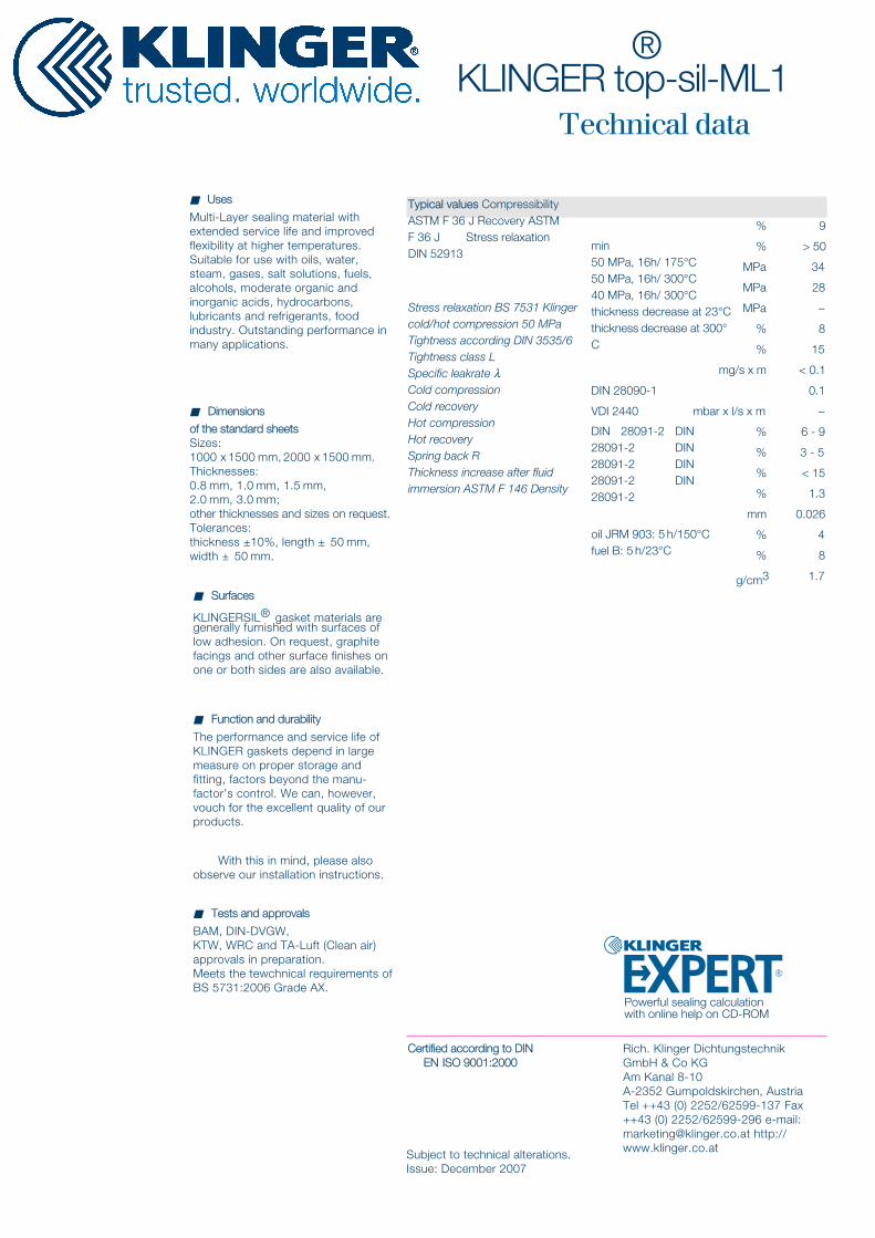
Typical values Compressibility ASTM F 36 J Recovery ASTM F 36 J Stress relaxation DIN 52913
Stress relaxation BS 7531 Klinger cold/hot compression 50 MPa Tightness according DIN 3535/6 Tightness class LSpecific leakrate λCold compression Cold recoveryHot compression Hot recoverySpring back RThickness increase after fluid immersion ASTM F 146 Density
9
> 50
34
28
–
8
15
< 0.1
0.1
–
6 - 9
3 - 5
< 15
1.3
0.026
4
8
1.7
%
%
MPa
MPa
MPa
%
%
mg/s x m
mbar x l/s x m
%
%
%
%
mm
%
%
g/cm3
■ Uses
Multi-Layer sealing material with extended service life and improved flexibility at higher temperatures. Suitable for use with oils, water, steam, gases, salt solutions, fuels, alcohols, moderate organic and inorganic acids, hydrocarbons, lubricants and refrigerants, food industry. Outstanding performance in many applications.
■ Dimensions
of the standard sheetsSizes:1000 x 1500 mm, 2000 x 1500 mm. Thicknesses:0.8 mm, 1.0 mm, 1.5 mm,2.0 mm, 3.0 mm;other thicknesses and sizes on request. Tolerances:thickness ±10%, length ± 50 mm, width ± 50 mm.
■ Surfaces
KLINGERSIL® gasket materials are generally furnished with surfaces of low adhesion. On request, graphite facings and other surface finishes on one or both sides are also available.
■ Function and durability
The performance and service life of KLINGER gaskets depend in large measure on proper storage and fitting, factors beyond the manu-factor’s control. We can, however, vouch for the excellent quality of our products.
With this in mind, please also observe our installation instructions.
■ Tests and approvals
BAM, DIN-DVGW, KTW, WRC and TA-Luft (Clean air) approvals in preparation.Meets the tewchnical requirements of BS 5731:2006 Grade AX.
Rich. Klinger Dichtungstechnik GmbH & Co KGAm Kanal 8-10A-2352 Gumpoldskirchen, Austria Tel ++43 (0) 2252/62599-137 Fax ++43 (0) 2252/62599-296 e-mail: [email protected] http://www.klinger.co.atSubject to technical alterations.
Issue: December 2007
Certified according to DIN EN ISO 9001:2000
Powerful sealing calculation with online help on CD-ROM


![Klinger Sentry Gasket · &vehjsvh ,ieh 3j½gi 8li /pmrkiv &ymphmrk ;levjihepi 6seh )yvs[e] 8vehmrk )wxexi bd4 6sg 8ip *e\ )qemp iruymvmiw$opmrkivyo gs yo](https://img.dokumen.tips/doc/110x75/5abff3b67f8b9a7e418ec651/klinger-sentry-ieh-3jgi-8li-pmrkiv-ymphmrk-levjihepi-6seh-yvse-8vehmrk-wxexi.jpg)