Embed Size (px)
Citation preview

Mechanics, Materials Science & Engineering, October 2015 ISSN 2412-5954
MMSE Journal. Open Access www.mmse.xyz 112
Kinematics and Load Formulation of Engine Crank Mechanism
Hailemariam Nigus1a
1 Federal TVET Institute, School of Mechanical Technology, Automotive Technology Department, Addis Ababa, Ethiopia
Keywords: kinematics, cranks mechanism
ABSTRACT. This paper presents the kinematics formulation of an internal combustion engine crank mechanism. The kinematics formulation of the crank mechanism is done using vector loop method and cosine rule are applied to describe the position of the piston. Following the velocity of piston and connecting rod is performed by differentiating the position in terms of the crank angle and connecting rod angle respectively. The acceleration equation with brief form is derived from the velocity in the same principle. Based on the kinematics, the equations of motion of crank mechanism components are formulated for each moving link and platform then, all motion parameters of each component about its crank angle are readily derived. Furthermore the 2D model is provided by using 2D Auto CAD software in order to visualize the system and mathematical algorithm solved by using software MATLAB. The forces acting on the crank mechanism and the torque applied are also formulated based on the angles of the crank and connecting rod.
1. Introduction. The Internal combustion engine is those that burn their fuel which is mixture of air and petrol from carburetor inside the cylinder or compress air only on the cylinder and injects diesel from injector nozzle. These IC engines convert the chemical energy stored in their fuel into heat energy during the power stroke of piston. The energy produced from burning of fuel is used for motion of piston; the working of a four stroke engine is based on simple slider crank mechanism. The kinematics of IC engine is not altering from simple slider crank mechanism. The kinematics formulation of the crank mechanism such as piston motion and connecting rod motion utilizes different software and methodologies for which it is suitable for manipulation The crank mechanism comprised of components like crank shaft, connecting rod and piston which changes the sudden displacement to a smooth rotary output which is the input to many devices such as pumps generators and compressors.
A detailed procedure of getting stresses in the fillet area of a crank mechanism particularly crank shaft was introduced by Henry et al. [1], in which FEM and BEM (Boundary Element Method) were used. Obtained stresses were ratified by experimental results on turbocharged compression ignition engine with Ricardo type combustion chamber configuration. The crank mechanism durability assessment tool used in this study was developed by RENAULT Guagliano et al. [2] conducted a study on a marine diesel engine crankshaft and connecting rod. Payer et al. [3] developed a two-step technique to perform nonlinear transient analysis of crank mechanism combining a beam-mass model and a solid element model and Prakash et al. [4] performed stress and fatigue analysis on three example parts belonging to three different classes of engines, light automotive crankshaft was studied by Borges et al. [5]. The geometry of the crank mechanism was geometrically restricted due to limitations in the computer resources available to the authors. Shenoy and Fatemi [6] conducted dynamic analysis of loads in the connecting rod and piston components, which is in contact with the crankshaft. Dynamic analysis of the connecting rod is similar to dynamics of the crankshaft, since these components form a slide-crank mechanism and the connecting rod motion applies dynamic load on the crank-pin bearing. Shenoy and Fatemi [7] optimized the crank mechanism considering

Mechanics, Materials Science & Engineering, October 2015 ISSN 2412-5954
MMSE Journal. Open Access www.mmse.xyz 113
dynamic service load on the component. It was shown that dynamic analysis is the proper basis for fatigue performance calculation and optimization of dynamically loaded components. A literature survey by Zoroufi and Fatemi [8] focused on durability performance evaluation and comparisons of forged steel and cast iron crankshafts.
The piston-connecting rod-crankshaft assembly in the reciprocating piston-engines is used to transform the gas forces generated during combustion within the working cylinder into a piston stroke, which the crankshafts converts into useful torque available at the flywheel. The cyclic operation leads to unequal gas forces, and the acceleration and deceleration of the reciprocating power-transfer components generate inertia forces. The inertia force components are identified as inertial forces of the 1st, 2nd, 4th order, depending upon their rotational frequencies, relative to engine speed. In the case of multi-cylinder engines, free moments of inertia are present when all the complete
As a result of operating gas, inertia and centrifugal forces, crank mechanism is loaded with forces that can be calculated analytically by the expression. It is normal to talk about the average peak cylinder pressure and standard deviation of maximum pressure. This variability both cycle to cycle and cylinder to cylinder is one source of half order excitation. The gas force that acts on the piston also acts on the cylinder head. The force on the piston splits into two components, one acting down the rod and one acting sideways on the cylinder wall. The forces are reacted at the main bearing but a couple exists between the horizontal reaction at the bearing and the piston side force. This couple is equal to the crankshaft output torque, so the crankshaft torque is reacted by forces on the engine structure.
2. Kinematics of crank Mechanism. Crank mechanism comprises of piston, connecting rod and crank shaft. In formulation of the crank mechanism such as piston kinematics and connecting rod kinematics of an engine need parameters of already existing engine, the given parameters are stated in table 1 and 2.
Table 1. Specification of the engine Capacity 345 cc
Number of Cylinders 4
Bore x Stroke 57.8 x 52mm
Compression Ratio 18:1
Maximum Torque 14.7 Nm @ 3600 rpm
Maximum Power 8.1hp @ 3600 rpm
Maximum gas pressure 25 bar
Table 2. Engine parameter Connecting rod length 113
Crank radius 26
Piston diameter 57.5
Stroke 52

Mechanics, Materials Science & Engineering, October 2015 ISSN 2412-5954
MMSE Journal. Open Access www.mmse.xyz 114
Fig. 1. Crank Mechanism
From the crank mechanism depicted in figure 1 I calculate the crank mechanism equation as follows. The mean piston velocity of the four stroke engine is calculated as eq(1) given
, (1)
where mean piston velocity;
stroke (from TDC to BDC);
engine speed, rpm.
2.1 Kinematic Modeling of Piston Motion. Piston is one of the main parts in the engine and its purpose is to transfer force from expanding gas in the cylinder to the crankshaft via a connecting rod.
2.1.1 Piston Instantaneous Position. The instantaneous piston position is formulated using the vector loop method from the figure 1 and 2 depicted
, (2)
where position from crank center to piston pin center;
l connecting rod length;
crank radius;
x instantaneous piston position from piston pin to TDC.
As it is depicted in figure 1 we can draw the schematic diagram of crank mechanism components relationship.

Mechanics, Materials Science & Engineering, October 2015 ISSN 2412-5954
MMSE Journal. Open Access www.mmse.xyz 115
Fig. 2. Relation b/n crank radius and connecting rod length and distance from piston pin axis to crank axis
As in figure2 depicted above it is possible to formulate between the variables of crank mechanism.
, (3)
. (4)
From equation 4 we can rearrange in angle phi form
(5)
. (6)
Equation 6 can be factorized and as the powers of lambda ( ) becomes higher and higher it approaches to null as a result:
, (7)
And rearranging the equation 7 in suitable form gives

Mechanics, Materials Science & Engineering, October 2015 ISSN 2412-5954
MMSE Journal. Open Access www.mmse.xyz 116
, (8)
To formulate the piston instantaneous displacement in the crank mechanism we can calculate based on figure 1 as follows:
. (9)
To be suitable in manipulating it is better to express the equation in easily estimated variable such that angle phi is very difficult to estimate so it is better to express the equation in terms of an angle theta which is the crank angle. Therefore, Substitute equation (9) in equation (2) provides:
. (10)
Collect like terms to gather and gives
. (11)
Substitute equation (8) in to equation (11)
(12)
This is the instantaneous position of piston from piston pin center to TDC in crank mechanism.
Where the ratio of crank radius to connecting rod length.
2.1.2 Piston Instantaneous Velocity. Having the instantaneous position of piston equation in equation (12) it is easy to drive the instantaneous velocity of the piston on the crank mechanism
, (13)
where derivative of piston instantaneous position;
derivative of crank angle;
dt time derivative;
angular speed;
insv instantaneous piston velocity.
The first derivative of equation (12) with respect to crank angle in substitute to equation (13)

Mechanics, Materials Science & Engineering, October 2015 ISSN 2412-5954
MMSE Journal. Open Access www.mmse.xyz 117
(14)
2.1.3. Piston Instantaneous Acceleration. The instantaneous acceleration of the piston is done the same as in instantaneous velocity did.
(15)
where instantaneous acceleration of piston.
2.1.4. Piston Pin Position. The displacement of the piston with respect to crank angle can be derived from simple trigonometry. This can then be differentiated to yield velocity and acceleration of the piston. The expressions obtained tend to be very complicated and can be simplified into the expression containing only first order (once per revolution), second order (twice per revolution), and a negligible fourth order.
The piston pin position is the position from crank center to the piston pin center and can be formulated from cosine rule of the trigonometry in fig.2
(16)
From the above polynomial equation degree two we can drive the piston position as follows:
. (17)
2.1.5 Piston Pin Velocity. Piston pin velocity is the upward velocity from crank center along cylinder bore center and can be calculated as the first derivative of equation 16 with respect to angle theta.
, (18)
where piston pin velocity.
To express the velocity with respect to time
. (19)

Mechanics, Materials Science & Engineering, October 2015 ISSN 2412-5954
MMSE Journal. Open Access www.mmse.xyz 118
2.1.6. Piston Pin Acceleration. Piston pin acceleration is the upward acceleration from crank center along cylinder bore center and can be calculated as the second derivative of equation 16 with respect to angle theta.
. (20)
To express the acceleration with respect to time can be express as
(21)
Fig. 3. Piston Kinematics
2.2. Kinematics Modeling of Connecting Rod Motion. The connecting rod is a major link inside of a combustion engine. It connects the piston to the crankshaft and is responsible for transferring power from the piston to the crankshaft and sending it to the transmission. Connecting rod as one component of the crank mechanism it is crucial to formulate the kinematics of connecting rod
2.2.1. Instantaneous Velocity Connecting Rod
dtd
dd
dtdvcon
(22)
where instantaneous velocity of connecting rod.
Differentiate equation (5) with respect to angle theta
Mechanics, Materials Science & Engineering, October 2015 ISSN 2412-5954
MMSE Journal. Open Access www.mmse.xyz 119
, (23)
(24)
2.2.2. Instantaneous Acceleration of Connecting Rod
, (25)
Differentiating equation 24 with respect to time
(26)
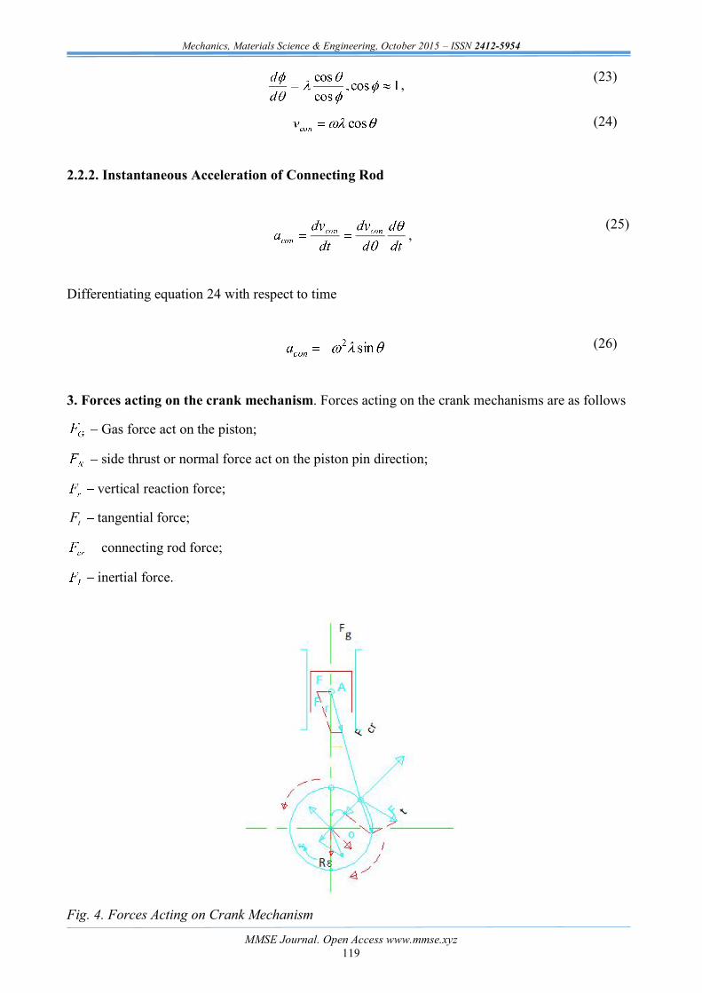
3. Forces acting on the crank mechanism. Forces acting on the crank mechanisms are as follows
Gas force act on the piston;
side thrust or normal force act on the piston pin direction;
vertical reaction force;
tF tangential force;
connecting rod force;
inertial force.
Fig. 4. Forces Acting on Crank Mechanism

Mechanics, Materials Science & Engineering, October 2015 ISSN 2412-5954
MMSE Journal. Open Access www.mmse.xyz 120
3.1. The Gas Force. Gas force is generated by the fuel combustion acting on the piston to be transferred to the crankshaft by connecting- rod through the expansion stroke: therefore during the complete cycle they depend on the crankshaft position.
When multiplied by the crank radius, the gas forces produce a periodically variable torque value. In multiple cylinder engines, the torque curve of the individual cylinders are superimposed with a phase shift dependent on the numbers of cylinders, their configuration, crankshaft design and firing sequence. The resulting composite curve is characteristics of the engine design and covers a full working cycle.
whole-number multiples of the basic frequencies
The cyclic torque fluctuation s rotation speed, called cyclic variation and defined as:
(27)
where cyclic torque fluctuation.
The gas force is the product of maximum pressure and area of the cylinder.
(28)
3.1.1. Gas Torque. torque resulting from gas pressure alone is represented by the equation:
(29)
Where Tg gas torque, Nm;
Pg gas pressure, Nm-2;
A area of top of piston, m-2.
3.2. Inertia Force. Inertia force is obtained by multiplying the piston acceleration by the reciprocating mass and acts only in the line of the cylinders.
(30)
where MREC reciprocating mass (piston mass plus approximately 2/3 conrod mass).

Mechanics, Materials Science & Engineering, October 2015 ISSN 2412-5954
MMSE Journal. Open Access www.mmse.xyz 121
Fig. 5. Torque Resulting from Gas pressure
3.2.1 Inertial Torque. The torque resulting from piston motion is often called the INERTIA torque and is represented by the equation:
(31)
Torsional Excitation of Crankshaft and Engine Structure - The total torque acting on the crankshaft of the single cylinder engine results from the effect of the gas and inertia forces on the crank slider mechanism.
Fig. 6. Torque resulting from piston motion alone for a single cylinder engine
3.2.2. The total torque. Total torque is found by summing these two components.

Mechanics, Materials Science & Engineering, October 2015 ISSN 2412-5954
MMSE Journal. Open Access www.mmse.xyz 122
Note that the torque from gas pressure dominates (for the engine firing case).
Fig. 7. Total Torque
3.3. Other forces. The forces like tangential force, connecting rod force and side thrust force can be calculated as it depicted in figure 3 the relationship is:
, (32)
, (33)
, (34)
. (35)
Summary. The modeling methodology for kinematics of crank mechanism has been derived systematically by considering the geometric configuration of the internal combustion engine crank mechanism. The forces and torque applied to the crank mechanism also properly analyzed. The conclusions are drawn as follows:
1. Through consideration of the crank mechanism the position, velocity and acceleration is properly formulated.
2. The relationship between the forces and torques applied in the crank mechanism such as gas force, inertial force, side thrust force, and tangent force and connecting rod force are properly addressed.
Acknowledgment
I would like to express my heartiest thank to my beloved wife Lemlem Tadesse who has always supported my dreams and motivated me to achieve them. I dedicate this work to her unending love and unconditional support.
References
A New 3-SAE Technical Paper No. 920087, Society of Automotive Engineers.

Mechanics, Materials Science & Engineering, October 2015 ISSN 2412-5954
MMSE Journal. Open Access www.mmse.xyz 123
Journal of Mechanical Design, Vol. 115, pp. 47-52.
[3] Payar, E., KaiSAE Technical Paper No. 950709, Society of Automotive
Engineers.
proach to Crankshaft SAE Technical Paper No. 980565, Society of Automotive Engineers.
Using a Geometrucally Restricted F SAE Technical Paper No. 2002-01-2183, Society of Automotive Engineers.
IMechE, Journal of Mechanical Engineering Science, Vol. 220, No. 5, pp. 615-624.
[7] Shenoy, P. S. and Fatemi, A., "Connecting Rod Optimization for Weight and Cost Reduction", SAE Paper No. 2005-01-0987, SAE 2005 Transactions: Journal of Materials and Manufacturing.
[8] Zoroufi, M. and Fatemi, A., "A Literature Review on Durability Evaluation of Crankshafts Including Comparisons of Competing Manufacturing Processes and Cost Analysis", 26th Forging Industry Technical Conference, Chicago, IL, November 2005.
[9] Xiaorong Zhou., Ganwei Cai., Zhuan Zhang. Zhongqing Cheng.,
Measuring Technology and Mechatronics Automation.
[10] Yadav Vinod and Mittal N.D , Design and Analysis of Piston Design for 4 Stroke Hero Bike Engine, International Journal of Engineering Innovation & Research, Vol. 2, page 148 150 , 2013.
[11] Anusha B and Reddy C.Vijaya Bhaskar, Modeling and Analysis of Two Wheeler Connecting Rod by Using Ansys , Journal of Mechanical and Civil Engineering, Vol.6, Page 83-87, May. - Jun. 2013.
[12] Norton R.L., Kinematics and Dynamics of Machinery, Tata McGraw Hill Education (P) Ltd., New Delhi, 2012.


![KINEMATICS - new.excellencia.co.innew.excellencia.co.in/college/web/pdf/Kinematics-merged.pdf · KINEMATICS KINEMATICS WORKSHEET 1 1) Displacement is a _____ [ ] 1) Vector quantity](https://img.dokumen.tips/doc/110x75/5f356d4687229051801abace/kinematics-new-kinematics-kinematics-worksheet-1-1-displacement-is-a-.jpg)


](https://img.dokumen.tips/doc/110x75/545b75b6b1af9fb66e8b62a2/5954-188091.jpg)
![[5954 - 18809]historia_da_arte (2)](https://img.dokumen.tips/doc/110x75/55cf9913550346d0339b680a/5954-18809historiadaarte-2.jpg)