Embed Size (px)
Citation preview

1ANSYS Inc. SEMATECH Workshop, March, 16 2010
1
Reliability Modeling Techniques Applicable to 3D-Packaging Using TSV
Reliability Modeling Techniques Applicable to 3D-Packaging Using TSV
Kamal KarimanalANSYS Inc.
Presented at
SEMATECH Workshop on Stress Management for 3D ICs Using
Through Silicon Vias March, 16 2010
Kamal KarimanalANSYS Inc.
Presented at
SEMATECH Workshop on Stress Management for 3D ICs Using
Through Silicon Vias March, 16 2010

2ANSYS Inc. SEMATECH Workshop, March, 16 2010
IC Packaging Challenges addressable by FEA Simulation
Board Level Interconnect Reliability
Solder Bump ReliabilityAccounting for Underfill
Interface Delamination
Fracture Mechanics at Silicon Level
3ANSYS Inc. SEMATECH Workshop, March, 16 2010
3
Today’s Focus:
Techniques Applicable to TSV based 3D packaging

4ANSYS Inc. SEMATECH Workshop, March, 16 2010
Causes for damage
• Externally imposed loads– Heat sink mounting forces– Shock, vibration, drop event
• Thermo-Mechanical stresses originating from within the IC– Due to CTE Mismatch
5ANSYS Inc. SEMATECH Workshop, March, 16 2010
Simulation Techniques for Common Package Design Challenges
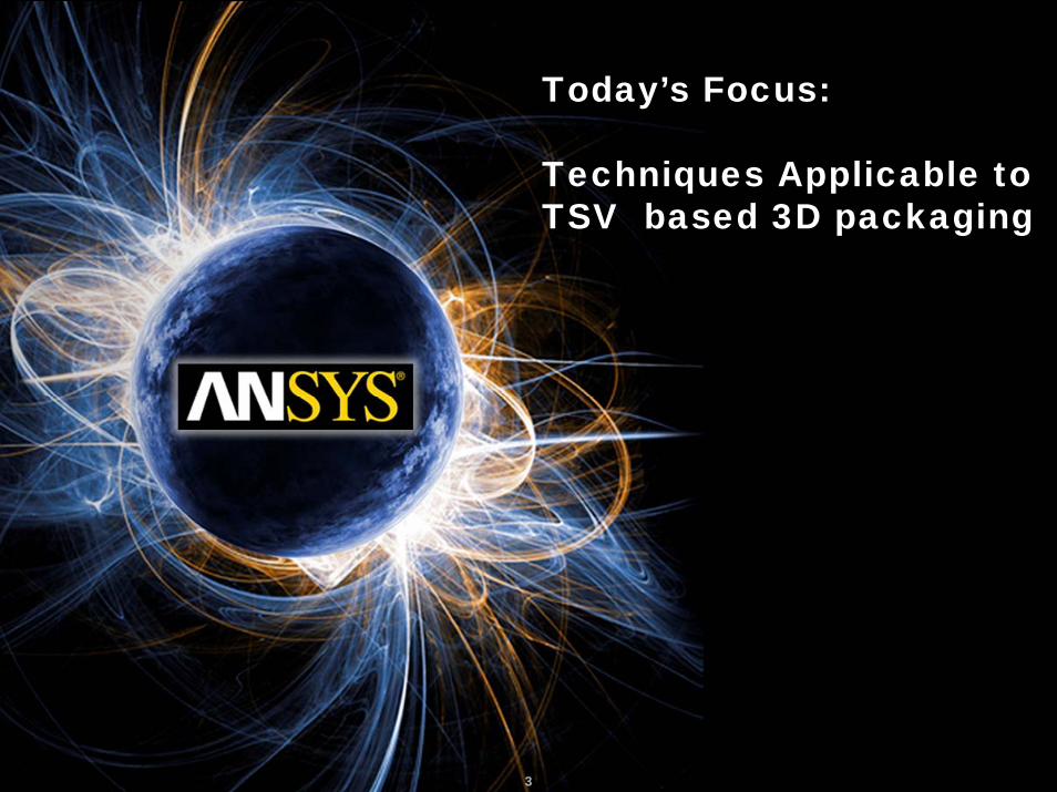
• Creep Failure of solder joints– Rate Dependent and Rate independent plasticity modeling– Coffin Manson type fatigue models
• Fracture of Silicon– Fracture Mechanics Models
• Interface Delamination– Cohesive Zone Modeling
• Multi-Scale Modeling Challenges– Sub-modeling
• Temperature Prediction Accuracy– Non uniform substrate conductivity mapping due to copper-FR4
non homogeneities• This is applicable to predicting 3D Package temperature distribution
6ANSYS Inc. SEMATECH Workshop, March, 16 2010
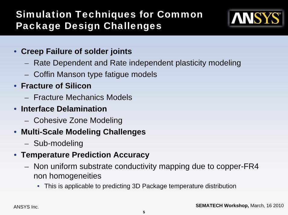
Thermo-Mechanics 101
CTEVdTdV
−= αα ,
At Elevated Temperature
At Temperatures levels below un-deformed state
Low CTE
High CTE
Un-deformed state
7ANSYS Inc. SEMATECH Workshop, March, 16 2010
7
Simulation Techniques & Their Applicability to 3D-Packages
Simulation Techniques & Their Applicability to 3D-Packages

8ANSYS Inc. SEMATECH Workshop, March, 16 2010
Solder Joint Reliability at PCB/substrate Interface
• This may be treated the same way as being done for the traditional packages– Based on 2 types of models
• Constitutive models for the solder material
• Coffin Manson type fatigue model
Board & substrate Level SJR
( ) ( ) ( ) ( )Tftfffcr 4321 εσε =&

9ANSYS Inc. SEMATECH Workshop, March, 16 2010
Traditional Solder Joint Reliability
• Popular Constitutive models– Material properties
• Anand Rate Dependent Plasticity Models• Hyperbolic Sine Creep Law (Gerafalo Model)
• Generic form of Coffin Manson Fatigue Relationship• Crack Initiation:
• Crack growth:
• Characteristic life:
210
KKN ψ=
43
KKdNda ψ=
dNda
aNW += 0α
Ψ is the damage sensitive parameterExample, strain energy density
K1, K2, K3, K4 determined by curve fitting test vs. simulation

10ANSYS Inc. SEMATECH Workshop, March, 16 2010
SJR at stacked die interface?
• Probably not an issue– Since same material is on either side of the
micro bumps– Differential thermal expansion comes from
temperature gradients
Micro bumps at stacked die interface
11ANSYS Inc. SEMATECH Workshop, March, 16 2010
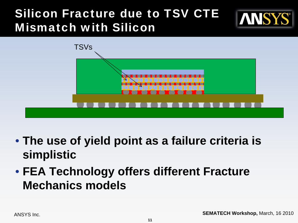
Silicon Fracture due to TSV CTE Mismatch with Silicon
• The use of yield point as a failure criteria is simplistic
• FEA Technology offers different Fracture Mechanics models
TSVs
12ANSYS Inc. SEMATECH Workshop, March, 16 2010
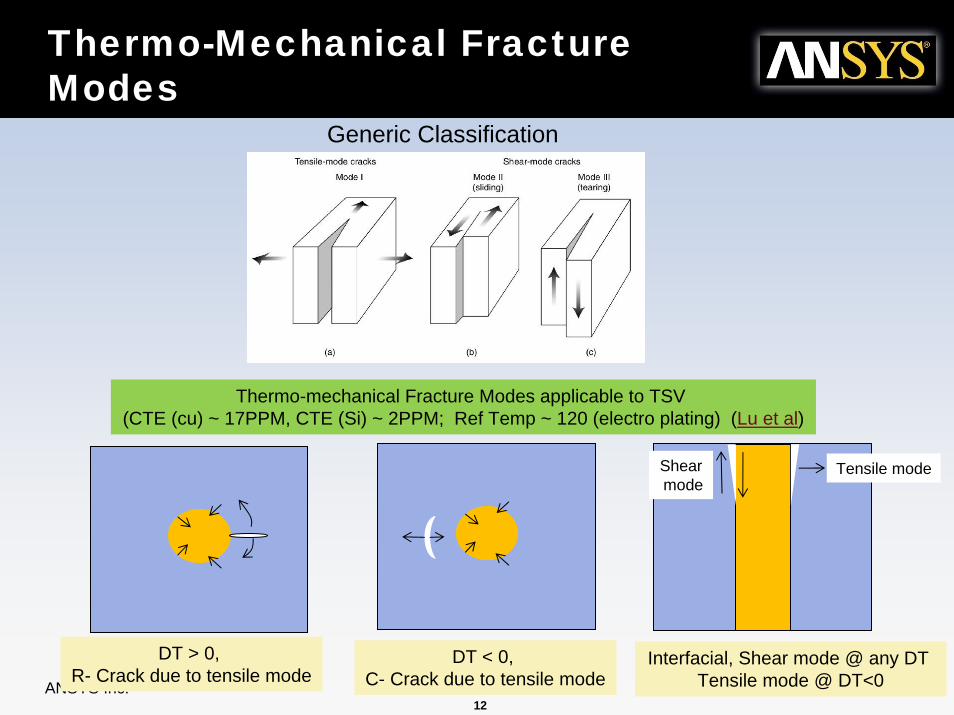
Thermo-Mechanical Fracture Modes
Generic Classification
Thermo-mechanical Fracture Modes applicable to TSV (CTE (cu) ~ 17PPM, CTE (Si) ~ 2PPM; Ref Temp ~ 120 (electro plating) (Lu et al)
DT > 0, R- Crack due to tensile mode
DT < 0, C- Crack due to tensile mode
Interfacial, Shear mode @ any DT Tensile mode @ DT<0
Tensile modeShearmode
13ANSYS Inc. SEMATECH Workshop, March, 16 2010
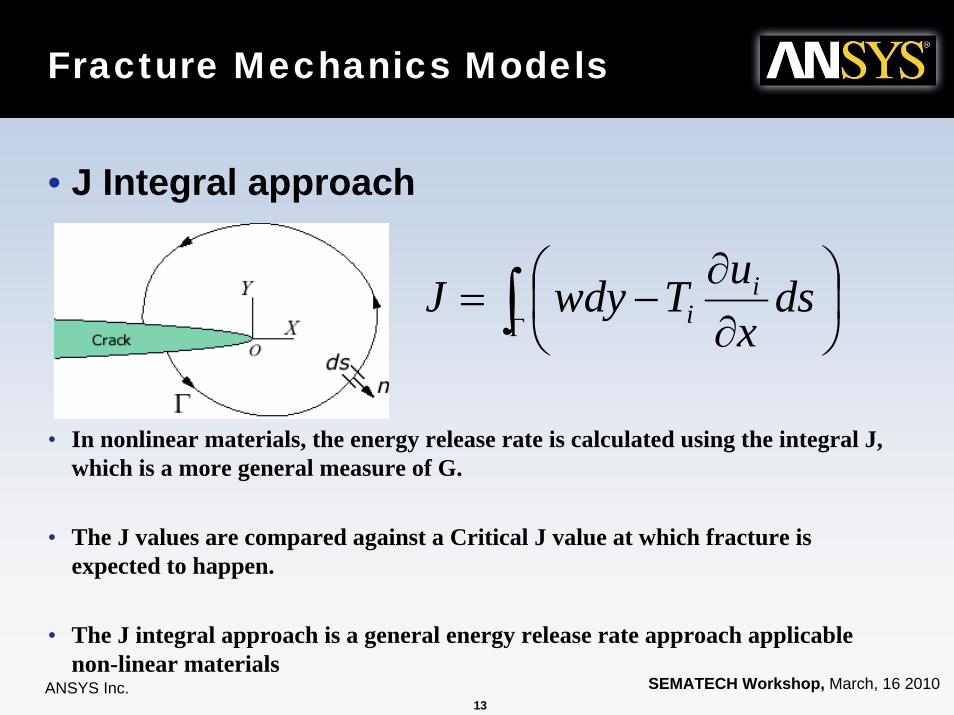
Fracture Mechanics Models
• J Integral approach
• In nonlinear materials, the energy release rate is calculated using the integral J, which is a more general measure of G.
• The J values are compared against a Critical J value at which fracture is expected to happen.
• The J integral approach is a general energy release rate approach applicable non-linear materials
∫Γ ⎟⎠⎞
⎜⎝⎛
∂∂
−= dsxuTwdyJ i
i
14ANSYS Inc. SEMATECH Workshop, March, 16 2010
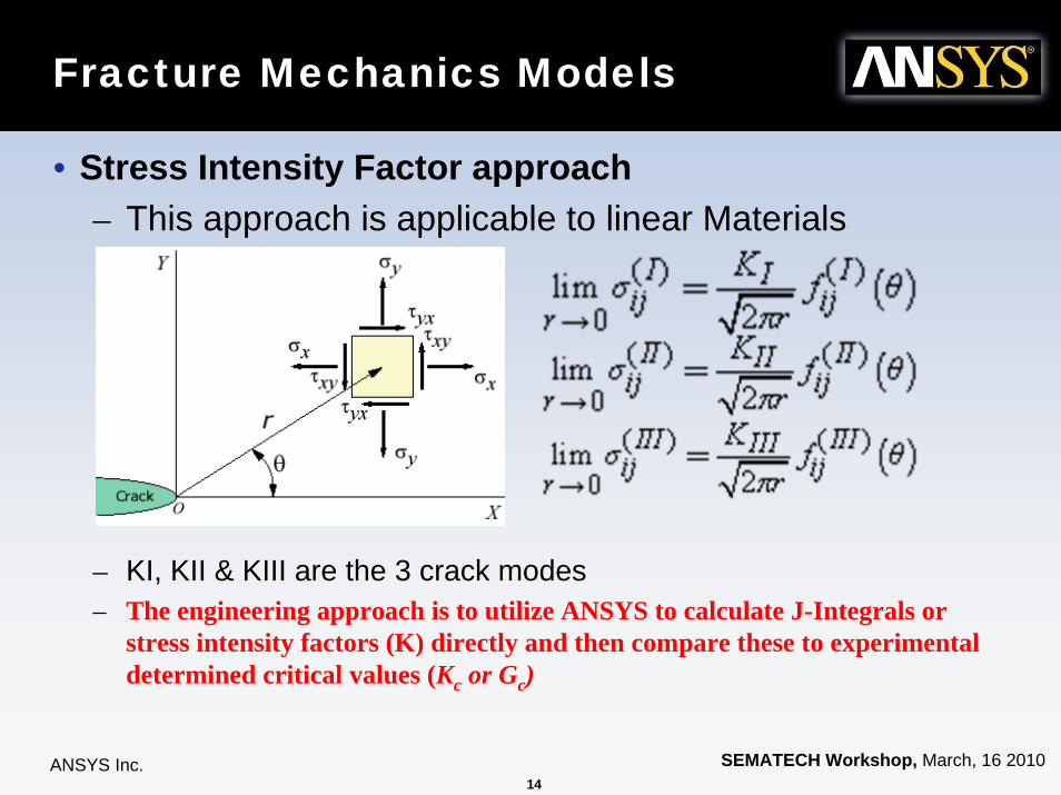
Fracture Mechanics Models
• Stress Intensity Factor approach– This approach is applicable to linear Materials
– KI, KII & KIII are the 3 crack modes– The engineering approach is to utilize ANSYS to calculate J-Integrals or
stress intensity factors (K) directly and then compare these to experimental determined critical values (Kc or Gc)

15ANSYS Inc. SEMATECH Workshop, March, 16 2010
15
DelaminationDelamination

16ANSYS Inc. SEMATECH Workshop, March, 16 2010
Delamination in 3D Packages
Delamination could occur at any of these interfaces
Die Thinning, microbumps, newMaterials & associated processesMakes delamination a non-trivial challenge
17ANSYS Inc. SEMATECH Workshop, March, 16 2010
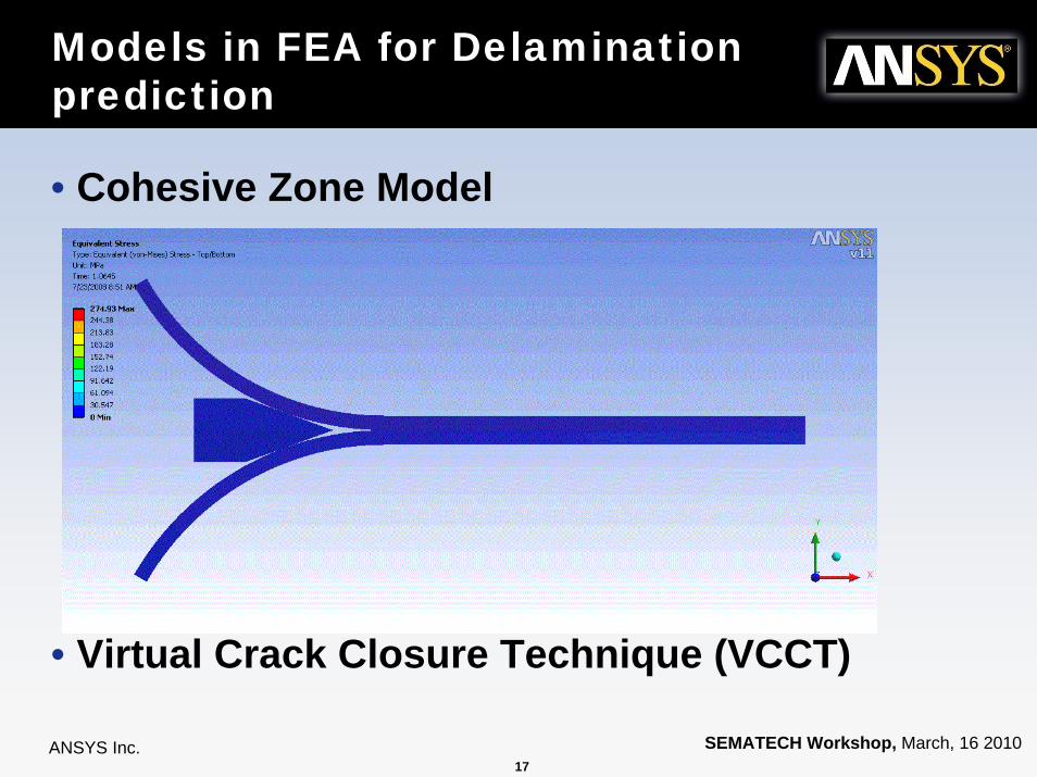
Models in FEA for Delamination prediction
• Cohesive Zone Model
• Virtual Crack Closure Technique (VCCT)

18ANSYS Inc. SEMATECH Workshop, March, 16 2010
Models in FEA for Delamination prediction
• Cohesive Zone Model
• Virtual Crack Closure Technique (VCCT)

19ANSYS Inc. SEMATECH Workshop, March, 16 2010
Cohesive Zone Model Inputs
• The user inputs at least three constants :– C1: Maximum normal traction at the interface σmax
– C2: Normal separation across interface at σmax when there is no shear separation
– C3: Shear separation across interface at τmax when there is no normal separation
nδ
tt δδ 2=

20ANSYS Inc. SEMATECH Workshop, March, 16 2010
Two types of models
• Exponential CZM Law not suited when there are unloading or reverse loading effects
• Bilinear Law accounts for unloading and reverse loading
• Can be specified using Traction-Separation or Critical Fracture energies
21ANSYS Inc. SEMATECH Workshop, March, 16 2010
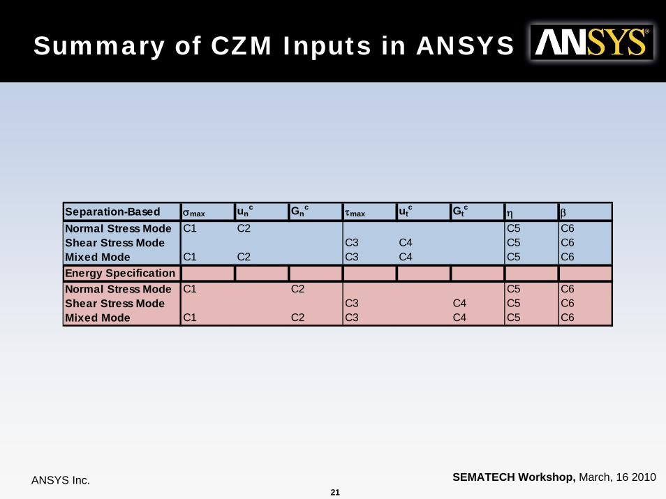
Summary of CZM Inputs in ANSYS
Separation-Based σmax unc Gn
c τmax utc Gt
c η βNormal Stress Mode C1 C2 C5 C6Shear Stress Mode C3 C4 C5 C6Mixed Mode C1 C2 C3 C4 C5 C6Energy SpecificationNormal Stress Mode C1 C2 C5 C6Shear Stress Mode C3 C4 C5 C6Mixed Mode C1 C2 C3 C4 C5 C6

22ANSYS Inc. SEMATECH Workshop, March, 16 2010
22
Tackling the Multi-Scale ChallengeTackling the Multi-Scale Challenge
23ANSYS Inc. SEMATECH Workshop, March, 16 2010
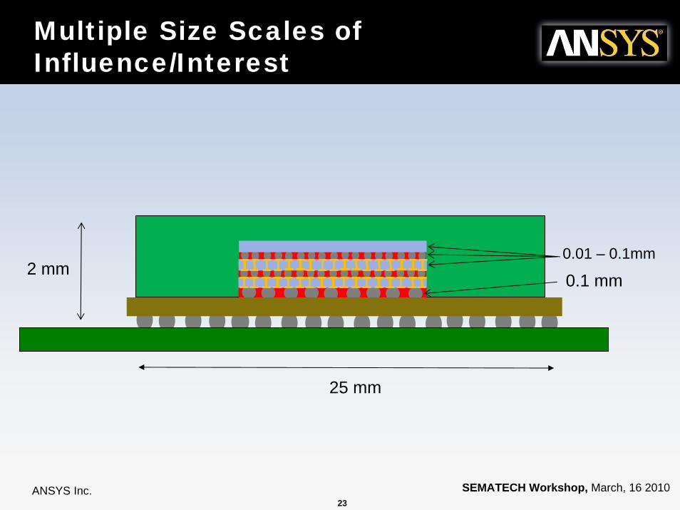
Multiple Size Scales of Influence/Interest
25 mm
2 mm0.1 mm0.01 – 0.1mm

24ANSYS Inc. SEMATECH Workshop, March, 16 2010
Submodeling - A Solution to the Size scale Challenge
• The Sub Modeling approacha) Full Package model with lumped properties
to identify critical risk areas• Hot spots and heat transfer pathways make this a
non-trivial taskb) Cut out Region with detailed geometry and
material models• Transfer Displacement profile from (a) to the cut
boundary– St. Venant’s Principle
• Transfer temperature distribution from the cut volume
25ANSYS Inc. SEMATECH Workshop, March, 16 2010
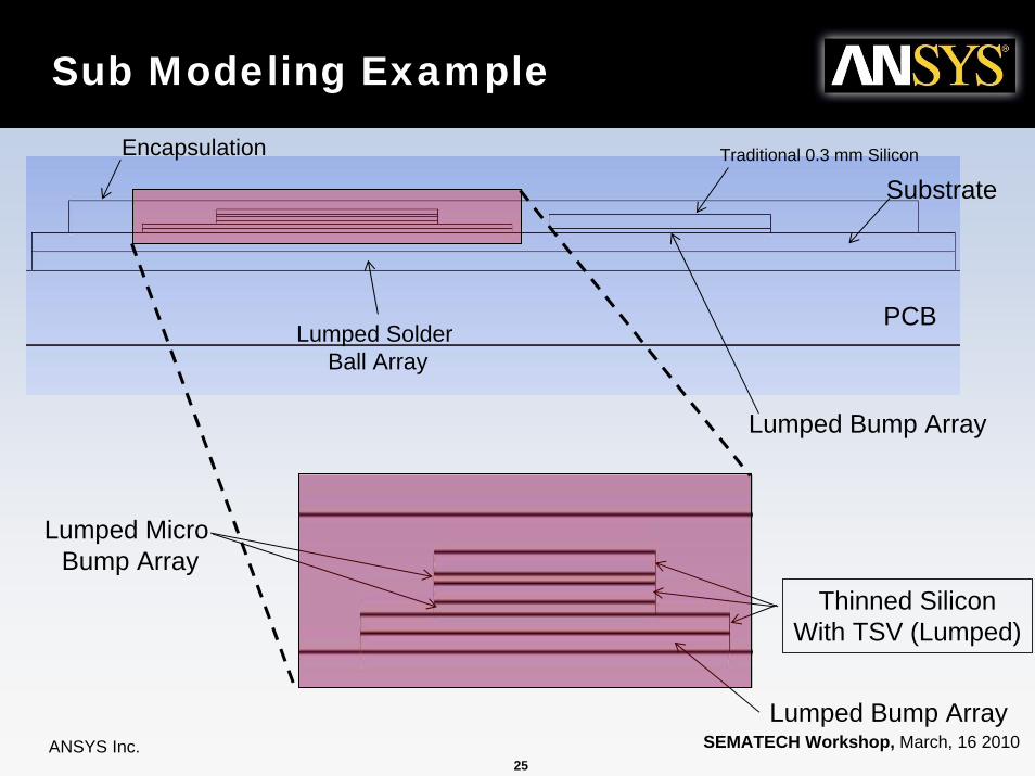
Sub Modeling Example
PCBLumped Solder
Ball Array
SubstrateEncapsulation
Lumped Bump Array
Traditional 0.3 mm Silicon
Lumped Bump Array
Thinned SiliconWith TSV (Lumped)
Lumped Micro Bump Array

26ANSYS Inc. SEMATECH Workshop, March, 16 2010
Sub Modeling Example (Continued)
2W Uniform & Steady
3 W on for 30 Sec & Off for 30 sec on 2 mm hot spot
300 Sec
330 Sec
360 Sec
Average power until Pseudo Steady state1.5 W
3 W
H = 25 W/m2/K on all external surfaces
27ANSYS Inc. SEMATECH Workshop, March, 16 2010
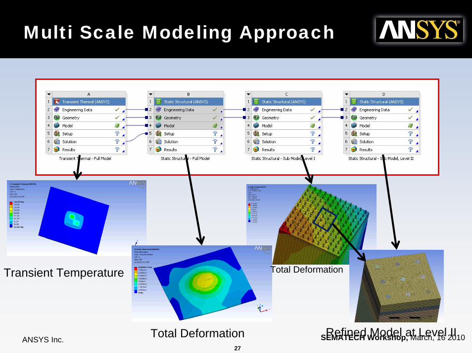
Multi Scale Modeling Approach
Transient Temperature
Total Deformation
Total Deformation
Refined Model at Level II

28ANSYS Inc. SEMATECH Workshop, March, 16 2010
Stress distribution in silicon with TSV

29ANSYS Inc. SEMATECH Workshop, March, 16 2010
29
Temperature Prediction Accuracy
Temperature Prediction Accuracy
30ANSYS Inc. SEMATECH Workshop, March, 16 2010
Importance of Temperature Prediction• Once past the road mapping and technology feasibility analysis,
tools are needed for analysis of specific designs.
• Design variations could be– Bump array distribution– Non-uniform TSV distribution– UBM & RDL metallization
• The above Distribution of metal play a crucial role in temperature distribution
• Techniques exist in ANSYS Icepak Software to account for metal distribution

31ANSYS Inc. SEMATECH Workshop, March, 16 2010
PCB & Substrate trace and plane modeling
• Trace & Planes can be read from Cadence, Gerber file formats
• Proprietary algorithm captures local variation of metal conductivity without needing to mesh traces– As result computationally practical
• Trace & Planes can be read from Cadence, Gerber file formats
• Proprietary algorithm captures local variation of metal conductivity without needing to mesh traces– As result computationally practical
ECAD Imported PCB

32ANSYS Inc. SEMATECH Workshop, March, 16 2010
Workflow for 3D-Packages
• Icepak tracemodeling poduces accurate temperature distribution
• WB platform allows easy coupling to Temperature distribution in Static structural analaysis
• Icepak tracemodeling poduces accurate temperature distribution
• WB platform allows easy coupling to Temperature distribution in Static structural analaysis
33ANSYS Inc. SEMATECH Workshop, March, 16 2010
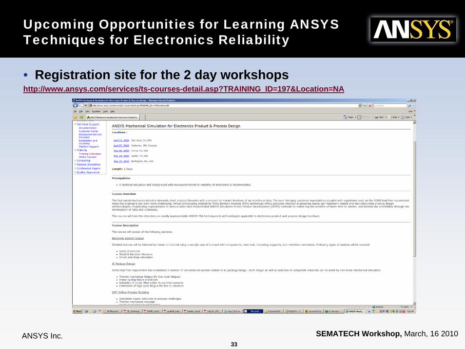
Upcoming Opportunities for Learning ANSYS Techniques for Electronics Reliability
• Registration site for the 2 day workshopshttp://www.ansys.com/services/ts-courses-detail.asp?TRAINING_ID=197&Location=NA

34ANSYS Inc. SEMATECH Workshop, March, 16 2010
Summary
• 3D Packaging with TSV poses new challenges– Can be addressed using traditional package FEA
modeling techniques
• Thermo-Mechanical stresses due to hot spots are dominant challenges
• Fracture and interface delamination challenges can be evaluated using FEA
• Sub-modeling is a key technique for refining multiple scales of interest