Embed Size (px)
Citation preview

Fuzzy Logic Control of a Parametrically Excited Rotating Beam
by
D. Boghiu, D.E. Marghitu and S.c. Sinha
Reprinted from
JOURNAL OFLOW FREQUENCY NOISE, VIBRATION
ANDACTIVE CONTROL
VOLUME 16 No.3 1997
MULTI-SCIENCE PUBLISHING CO. LTD.
107 High Street, Brentwood, Essex CM14 4RX, United Kingdom
Fuzzy Logic Control of a Parametrically ExcitedRotating Beam
Dan Boghiu, Graduate ResearcherDan B. Marghitu, Assistant Professor
S. C. Sinha, Professor
Nonlinear Systems Research Laboratory. Department of MechanicalEngineering. Auburn University. AL 36849. USA
(received 5 March 1997)
ABSTRACT.
In this paper the control of a parametrically excited. rotating flexible beam isconsidered. Only the flap motion of the elastic beam is analyzed. Due to anaxial harmonic excitation. the nonlinear equations of motion contain periodiccoefficients.A fuzzy logic controlleris designedsuch that the deflectionof thebeam tip can be limited to a desired value in a relatively short period of time.Such systems can be used as preliminary models for studying the flap dynamicsand control of helicopter rotor blades and flexible mechanisms. among other
systems. .
Keywords: fuzzy logic control. nonlinear time-periodic systems
1 INTRODUCTION
The behavior of flexible bodies connected to moving supports has been studiedfor a long period of time. Beams attached to moving bases have receivedspecial attention in many technical papers dealing with elastic linkages, rotatingmachinery, robot manipulator arms.
To control the motion of the flexible links, both linear and nonlinear
controllers were constructed and different kind of strategies were implemented.Adaptive control algorithms and on-line parameter identification techniqueshave been common features of the last generation controllers.
Cannon and Schmitz (1984) considered an elastic arm, modeled as a pinned-free beam, attached to a hub. The objective of their work was to carry outexperiments designed to determine the necessary control torque applied at thebase of the link suing only the tip position measurement. A more complexsystem was analyzed by Berbyuk (1984). His work was related to the problemof controlling the plane rotational motions of two rigid bodies connected by anelastic rod. Asymptotic methods were used to obtain a solution of the controlproblem for some limiting cases.
Nathan and Singh (1991) treated the problem of controlling an elastic arm oftwo links based on variable structure system theory and pole assignmenttechnique for stabilization. This design approach was motivated by a simpleobservation that the nonlinearity in the dynamics of an elastic robotic system isessentially due to the rigid modes Uoint angles), and as the time derivatives ofthe rigid modes vanish, the remaining motion is only due to the elasticity. Forthe rigid modes a sliding controller was designed. The controller of the elastic
Journal of Low Frequency Noise.Vibration and Active ControlVol. 16 No.3 1997
179

FUZZY LOGIC CONTROL OF A PARAMETRICALLY EXITED ROTATING BEAM
modes was constructed using the pole assignment technique. A similartechnique has been used by Singh et al. (1994) to control the motion of aflexible/rigid link robot.
Warren et al. (1995) designed a robust control system for a slewing shaft-beam system. The motivation for such a design was the control of flexiblestructures that need accurate pointing capabilities while rejecting structuralvibrations.
Boghiu, et al. (1996) studied the flap motion control of a rotatingparametrically excited flexible beam. A linear controller, based on theLyapunov-Floquet transformation, was constructed to suppress both thedeflection angle and the elastic vibrations of the beam. The controller designwas based on the idea suggested by Sinha and Joseph (1994).
In recent years, fuzzy logic controllers demonstrated their superiority inmany applications over conventional control schemes. This is mainly due totheir capacity to capture the approximate, inexact nature of a real world system.In fact, most of the dynamic processes have nonlinearities that are difficult tobe exactly modeled in mathematical forms. Lim and Hiyama (1991) proposedproportional-integral and fuzzy logic controllers to control a two link rigidrobot. The PI controller was used to ensure fast transient response and zerosteady-state error. The fuzzy-logic controller was used to enhance dampingcharacteristics of the system. However, they found that the gains adjustment ofthe PI controller requires a large effort and the control scheme does notcompensate for the nonlinear effects of the robot system.
Liu and Lewis (1992) designed a feedback-linearization/fuzzy logic hybridscheme for a robotic manipulator with link flexibility. The control scheme wascomposed of a feedback-linearization inner-loop control and a fuzzy linguisticouter-loop control. A reduced-order computed torque control was first used tolinearize the whole system to a Newton's law-like system, then a linguisticfuzzy controller (of 33 if-then fuzzy rules) is used to command the rigid modesto track a desired trajectory while the residual vibrations are maintained assmall as possible.
Kubica and Wang (1993) applied a fuzzy control strategy to control the rigidbody and the first flexural mode of vibration in a single link robotic arm. Twofuzzy logic controllers were constructed. The first one was designed to governthe rigid motion of the beam as it was rotated from one position to another. Thesecond controller was designed to attenuate the vibrations resulting from therigid body motion. The results obtained showed an improvement over thoseobtained using conventional multivariable techniques.
Beale and Lee (1995) developed a fuzzy logic control scheme to investigatethe vibration suppression of a flexible-rod slider mechanism. A three modeapproximation of the beam was considered. From simulations it was found thatthe transverse deflection of the flexible link was significantly reduced.
In this paper, a mechanical system similar to the one presented in (Boghiu etaI., 1996) is considered. However, the equations of motion are nonlinear and afuzzy logic strategy is designed to control the nonlinear flap motion of theelastic beam.
2 THE SYSTEM MODEL
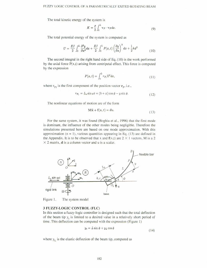
The diagram of the system is shown in Fig. 1. The system consists of a slenderflexible beam AB cantilevered onto a rigid massless base. The beam has lengthL, a constant flexural rigidity E I and a uniformly distributed mass per unit
length p = mIL, where m is the total mass. The base of length Lb = 2b has a
180

FUZZY LOGIC CONTROL OF A PARAMETRICALLY EXITED ROTATING BEAM
sinusoidal vibrating motion of amplitude La and frequency OJ.The base canperform small rotational deflections 4>(t)about the z axis passing through thepoint 0]. A spring and a damper are connected to the base and the rigid link inorder to avoid largerotation4>.The wholesystemrotatesin the horizontalplanewith a constant angular velocity O. Let x be the position of a point P on thebeam with respect to the end A of the base and y be the elastic deflection. Onlythe flap motion of the elastic link is considered. Two reference frames are used:a "fixed" reference frame (N), of unit vectors i,j and k, whose origin is at 0 anda rotating reference frame (R), of unit vectors m], mz and m3' with the origin at0 and attached to the rigid link 00]. These are related by the transformation
The position vector of point P in the rotating reference frame (R) is
rp = [Losinwt + (b+ x) cos~ - ysin~]m1 + [ycos~ + (b + x)sin ~]m3' (2)
The elastic deflection y of the beam is computed as
00
y(x, t) = L 1l1;(x)q;(t),;=1 (3)
where I\Jj(x)are the mode shapes of a cantilever beam. These are defined by theexpression
cosh(A;) + COS(A;) . .
1l1;(x) = cosh(z) - cos(z) - . heA) . (A \ (smh(z) - sm(z)),sm ; + sm ; (4)
whereXA;
z = L' (5)
and "'j (i =1,...,(0) are the consecutive roots of the transcendental equation
cos( A) cosh(>.) = -1. (6)
The mode shape functions satisfy the orthogonality relations
1L p'¥;(x)'¥,(x) dx = m 8;j,{L"" A;
Jo '¥;(x)'¥j(x)dx = L38;j, (7)
where O. is Kronecker delta function.IJ
The velocity of the point P, in the fixed reference frame (N), is computedusing the expression
Rdrp + fJ x rp,Vp = dt (8)
where the first term of the right hand side represents the derivative with respectto time in the moving reference frame (R).
181
m'1 r OMm
sinOt 0
m2 = - sin Ot cos Ot
0 II j I
(I)
m3J L 0 0 1 J lk
FUZZY LOGIC CONTROL OF A PARAMETRICALLY EXITED ROTATING BEAM
The total kinetic energy of the system is
P1
L
K = - Vp . vpdx.2 0 (9)
The total potential energy of the system is computed as
EI [L 82y EI [L (8y )2 1 2
U = ""2 Jo 8X2dx +""2 Jo P(X,t) 8x dx + 2krjJ (10)
The second integral in the right hand side of Eq. (10) is the work performedby the axial force P(x,t) arising from centripetal effect. This force is computedby the expression
P(x, t) = 1L rpl02dx, (I I)
where rpl is the first component of the position vector rp, i.e.,
rp1 = Lo sin wt + (b + x) cos rjJ- y sin rjJ. (12)
The nonlinear equations of motion are of the form
Mx + f(x, t) = duo(13)
For the same system, it was found (Boghiu et al., 1996) that the first modeis dominant, the influence of the other modes being negligible. Therefore thesimulations presented here are based on one mode approximation. With thisapproximation (n = I), various quantities appearing in Eq. (13) are defined inthe Appendix. It is to be observed that x and r(x,t) are 2 x I vectors, M is a 2x 2 matrix, d is a column vector and u is a scalar.
0~0
L~ ~~:,0
dg;d link "fa
flexible bar
base
Figure I. The system model
3 FUZZY-LOGIC CONTROL (FLC)In this section a fuzzy-logic controller is designed such that the total deflectionof the beam tip Ytis limited to a desired value in a relatively short period oftime. This deflection can be computed with the expression (Figure I)
Yt = Lsin rjJ+ YL cosrjJ(14)
where YLis the elastic deflection of the beam tip, computed as
182
FUZZY LOGIC CONTROL OF A PARAMETRICALLY EXITED ROTATING BEAM
YL(t) = y(L, t) = w1(L) ql(t). (15)
The inputs to the fuzzy -logic controller are the angle 4> and its timederivative 4>.The output of the controller is the torque u applied to the base ofthe elastic beam. For each input and output of the controller, a fuzzy set isassociated. The vector representation of a fuzzy set has two components: anuniverse of discourse vector (also called the support vector) and a membershipvector (also called the grade vector). The support vector represents the range ofthe input/output signal used to design the controller, while the grade vector canhave any value between 0 and I.
input
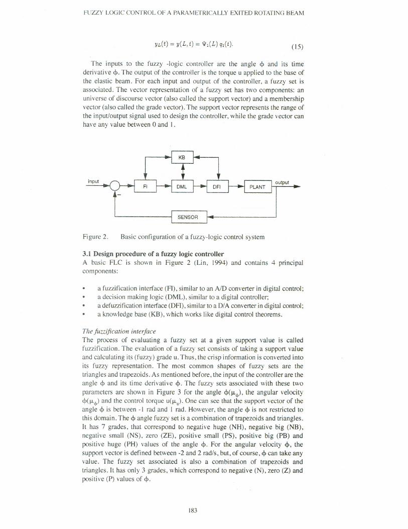
Figure 2. Basic configuration of a fuzzy-logic control system
3.1 Design procedure of a fuzzy logic controllerA basic FLC is shown in Figure 2 (Lin, 1994) and contains 4 principalcomponents:
. a fuzzification interface (FI), similar to an A/D converter in digital control;a decision making logic (DML), similar to a digital controller;a defuzzification interface (DFI), similar to a D/A converter in digital control;a knowledge base (KB), which works like digital control theorems.
...The fuzzification interfaceThe process of evaluating a fuzzy set at a given support value is calledfuzzification. The evaluation of a fuzzy set consists of taking a support valueand calculating its (fuzzy) grade u. Thus, the crisp information is converted intoits fuzzy representation. The most common shapes of fuzzy sets are thetriangles and trapezoids. As mentioned before, the input of the controller are theangle 4> and its time derivative 4>.The fuzzy sets associated with these two
parameters are shown in Figure 3 for the angle 4>(IL<f»'the angular velocity4>(IL<f»and the control torque u(J.J.). One can see that the support vector of theangle 4>is between -I rad and I rad. However, the angle 4>is not restricted tothis domain. The 4> angle fuzzy set is a combination of trapezoids and triangles.It has 7 grades, that correspond to negative huge (NH), negative big (NB),negative small (NS), zero (ZE), positive small (PS), positive big (PB) andpositive huge (PH) values of the angle 4>. For the angular velocity 4>, thesupport vector is defined between -2 and 2 rad/s, but, of course, 4> can take anyvalue. The fuzzy set associated is also a combination of trapezoids andtriangles. It has only 3 grades, which correspond to negative (N), zero (Z) andpositive (P) values of 4>.
183

FUZZY LOGIC CONTROL OF A PARAMETRICALLY EXITED ROTATING BEAM
The fuzzy set of the controller output u (Figure 3) consists only ofequidistant triangle grades. The control force has 5 components, thatcorrespond negative big (NB), negative small (NS), zero (ZE), positive small(PS), positive big (PB) values of the controller output.
Intuitively, when <I>and <I>are "zero", then the output of the controller shouldalso be "zero".
The decision-making logic
The decision making logic is the module in which the controller output isgenerated. It uses the input fuzzy sets, and the decision is taken according to thevalues of the inputs (angle <I> and 4». A consequence table is required and thecontroller output is generated using "If-Then" rules. The rule has two parts, anantecedent and a consequence. The antecedent is the "If' part and theconsequence is the "Then" part.
184
J.!,p1.0
I NH\ /\NB INSI /I IPS I PB/\ I PHCDC> 0.8c:<UCD- 0.6'00U
0.4CD>CD"
0.2C>CD
I-0.0
-1.0 -0.5 0.0 0.5 rjJ[rad]
./li?
1.0'u0
(jj> 0.8
"SC>c:
0.6<UCD.;'0 0.40UQ)> 0.2Q)"<UC,
0.0Q)-2.0 -1.5 -1.0 -0.5 0.0 0.5 1.0 1.5 rjJ[rad/s]I-
;:3 J.!uCD 1.0'"E!.8e 0.8c0uQ) 0.6.;'00 0.4UQ)>CD 0.2"C>Q)
0.0I-
-6.0 -4.0 -2.0 0.0 2.0 4.0 u[Nm]
Figure 3. The fuzzy-sets of the controller input and output

FUZZY LOGIC COI\'TROL OF A PARAMETRICALLY EXITED ROTATING BEAM
The consequence table is a matrix of 7 columns (the number of grades of the<I>angle fuzzy-set) and 3 rows (the number of grades of <I>fuzzy-set). Theconsequence table is as follows
As an illustration of the "If-Then" rules, let us suppose that <I>is negative by(NS) and <I>is positive (P). For this case, one has:
IF <I>is NEGATIVE BIG and <I>is POSITIVE,
THEN, u is POSITIVE SMALL.
Each time, according to the values of <I>and <1>,one or more "If-Then" rules
are used to compute the control torque u.
The defuzzificationinterface .
Defuzzification is the operation of obtaining a crisp number from a fuzzy setbased on the grades of the fuzzy set. Several defuzzification techniques arebased on maximum grade, minimum grade and centroid. The maximum(minimum) grade method selects the support value associated with themaximum (minimum) grade. The results of these methods may bediscontinuous in response to small changes in the original fuzzy sets' grades.The centroid method returns the "center of mass" of a fuzzy set. The centroidof a fuzzy set changes in a continuous manner as the shape of the set changes.This method is used in this paper to generate the numerical value of the controltorque u from its fuzzy set.
4 SIMULATIONS AND RESULTS
The following typical numerical values were used for simulations: lengths ofelastic beam (aluminium) L = 1.0 m, mass/unit length p =0.213 kg/m, flexuralrigidity E I = 34.852 N, amplitude of the parametric excitation Lo =0.02 m,spring constant k = 10 Nm/rad, damper constant c =2 Nms/rad.
The normalized natural frequencies of the linearized system were reported inBoghiu et al. (1996),for three mode shapes. They correspond to 131=4.74 rad/s,132=28.04 rad/s, 133=169.33rad/s,134= 473.49 rad/s,for a nonrotatingsystem(.0 =0 rad/s). For the rotatingsystem (.0 =20 rad/s) one has 131=6.76 rad/s,132=36.23 rad/s, 133=177.8 rad/s, 134=482.02 rad/s. In this work, simulationswere performedfor an excitationfrequencyof l1J= 131 + 132.In both cases, forthis value of the excitation frequency, the uncontrolled system is neutrallystable.
Using the' controller system procedure developed in the previous section,several simulations were performed. In all the cases, a typical initial conditionof <1>(0)=0.2 rad was used.
185
4> NH NB NS ZE PS PB PH
4>=N PB PB PS PS ZE NS NB
4>=Z PB PS ZE ZE ZE NS NB
4>=P PB PS ZE NS NS NB NB

FUZZY LOGIC CONTROL OF A PARAMETRICALLY EXITED ROTATING BEAM
;or 0.20c:0
"B 0.15~~ 0.10c.";::;E 0.05coQ)
~
c;; 0.00....0I- -0.05
3
Et:.
2
;:JQ):JtT5...,"2....c:0U
-1
-2
-30.0 0.1 0.2 0.3 0.4 0.5 0.6 0.7 0.8 0.9 t [5]
Figure 4. Damped-nonrotating system
a)
b)
c)
Figure 4 shows the results of a damped-nonrotating system. The total beamtip deflection Ytof the uncontrolled nonlinear system is shown in Figure 4.a.One can see that the system is neutrally stable. Figure 4.b shows the total beamtip deflection Ytof the controlled system. It is observed that the zero deflectionis reached in 0.4 s for the nonlinear controller. Figure 4.c shows the controltorque u generated by the nonlinear controller.
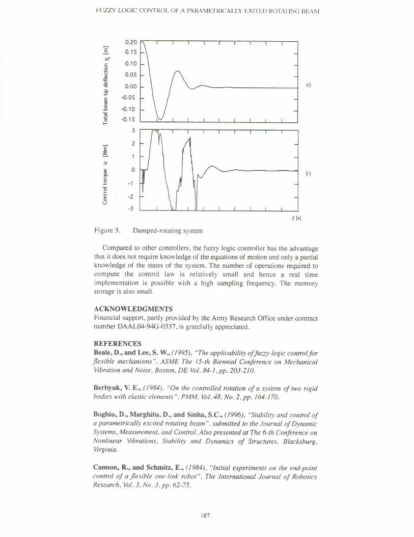
The results for the damped-rotating system are shown in Figure 5. Figure 5.ashows the behavior of the controlled system. The stabilization time is largerthan in the previous case (the influence of the rotation), and the system is moreoscillatory until the final position is reached. The control torque generated bythe fuzzy-logic controller is shown in Figure 5.b.
5 CONCLUSIONS
The control problem associated with a rotating nonlinear elastic beam with aparametrically excited base is considered. A fuzzy logic controller has beendesigned to control the flap motion of the elastic beam by bringing the totaldeflection of the beam-tip Ytto zero. The controller inputs were the rigid angle<!> and its time derivative and no information about the elastic coordinate ql wasrequired for the design or implementation of the controller.
186
I 0.3
;or 0.2c:0
";::;0.1u
Q)Q)
0.0""0C.";::;E -0.1coQ)
c;; -0.2....0I- -0.3
I 0.25
FUZZY LOGIC CONTROL OF A PARAMETRICALLY EXITED ROTATING BEAM
Figure 5.
I~c0
"'::;uQ)
c;::Q)
""C
a.''::;
0.20
0.15
0.10
a)
b)
t [s]
Compared to other controllers, the fuzzy logic controller has the advantagethat it does not require knowledge of the equations of motion and only a partialknowledge of the states of the system. The number of operations required tocompute the control law is relatively small and hence a real time
implementation is possible with a high sampling frequency. The memorystorage is also small.
0.05
0.00
E(I:!Q).c
(ij...0~
-0.05
-0.10
-0.15
ACKNOWLEDGMENTS
Financial support,partly provided by theArmy ResearchOffice undercontractnumberDAAL04-94G-0337, is gratefully appreciated.
3
Et:.2
REFERENCES
Beale, D., and Lee, S. W., (1995), "The applicability offuzzy-logic control forflexible mechanisms", ASME The 15-th Biennial Conference on MechanicalVibrationand Noise, Boston.DE-Vol.84-1.pp. 203-210.
;::!Q)::3C"
15..."5
'-...c0U
0
Berbyuk, V. E., (1984), "On the controlled rotation of a system of two rigidbodies with elastic elements". PMM, Vol. 48. No.2, pp. 164-170.
-1
-2
-3
Damped-rotating system
Boghiu, D., Marghitu, D., and Sinha, S.C., (1996). "Stability and control of(Iparametrically excited rotating beam", submitted to the Journal of DynamicSystems. Measurement. and Control. Also presented at The 6-th Conference onNonlinear Vibrations. Stability and Dynamics of Structures. Blacksburg.Virginia.
Cannon, R., and Schmitz, E., (1984). "Initial experiments on the end-pointcontrol of a flexible one-link robot", The International Journal of RoboticsResearch. Vol. 3, No.3. pp. 62-75.
187

FUZZY LOGIC CONTROL OF A PARAMETRICALLY EXITED ROTATING BEAM
Kubica, E., and Wang, D., (1993), "A fuzzy-control strategy for a flexiblesingle link robot", American Control Conference Proceedings, 236-241.
Lim, C. M., and Hiyama, T., (1991), "Application of fuzzy-logic control to amanipulator", 1EEE Transactions on Robotics and Automation, 7(5),688-691.
Lin, C. F., (1994), Advanced control systems design, Prentice Hall, EnglewoodCliffs, New Jersey.
Liu, K., and Lewis, F., (1992), "Fuzzy-logic control of a flexible linkmanipulator", Proc. SlNS' 1nternational Symposium 1mplicit NonlinearSystems, 21-26.
Nathan, P.J. and Singh,S. N., (1991), "Sliding mode control and elastic modestabilization ofa robotic arm with flexible links", Journal of Dynamic Systems,Measurement, and Control, Vol. 113,pp. 669-754.
Singh, T., Golnaraghi, M., and Dubey, R., (1994), "Sliding mode/shapedinput control offlexible/rigid link robot", Journal of Sound and Vibrations, Vol.171, No.2, pp. 185-200.
Sinha,S. c., and Joseph, P., (1994), "Control of general dynamic systems withperiodically varying parameters via Lyapunov-Floquet transformation", ASMEJournal of Dynamic Systems, Measurement, and Control, Vol. 116,pp. 650-658.
Warren, S., Voulgaris, P., and Bergman, L., (1995), "Robust control of aslewing beam system", Journal of Sound and Vibrations, No.1, pp. 251-271.
188

FUZZY LOGIC CONTROL OF A PARAMEfRICALLY EXITED ROTATING BEAM
APPENDIX
The various quantities appearing in the nonlinear equation of motion (13) aredefined as in the following.
.x is the generalized coordinates vector define by x = [4>,qdT;
. M is the mass matrix defined as
M =[
mL2/3 + qfG1 Fl
]
j
F1 G1
(16)
The functions F, and G) are defined as
F1 = lL xpwl(x)dx, G1= lL pw~(x)dx. (17)
. f(x,t) is a nonlinearvector
f(x, t) = [h h]T (18)where
j, = ebLo(02 + ",2) sin",t sin 4>+ Lo(02 + ",2)q, sin",t cos 4>VI+ k4>+
02 cos(24))F,q, - 02 cos 4><f>1l1q~/2 - (L2<f>~, - <f>;,)02q;sin 4»/4 +
hO' sin(24))/2 - 02G,q; sin(24))/2 + 2G,ql~q"
h = 02cos4>(L2<f>~, - <f>;,)q,j2 - 02G,q, sin24> + EIH,q, +
LoO'(L<f>~, - <f>:,)q, sin",t - 302<f>l1,q; sin 4>/2 + 02 F, sin(24))/2 +
LO(02 + ",2) sin",t sin 4>v, - G,q,~2.
The following notations where used
VI = lLpWl(X)dx, HI = lL (W;(x)Y dx,
0 rL ('
)2 1 rL ('
)2
iI>11 = 10 P WI(x) dx, iI>11= 10 px w1(x) dx,
iI>~1= lLpx2 (W~(X))2 dx, iI>111= lL (lL PWIWd~)(w~(x)rdx, 19)mL2 mL
!&=-, eb=-3 2 .
. d = II, Or is the input vector;
. u is the control torque applied to the moving base, as shown in Figure I.
189