Embed Size (px)
Citation preview
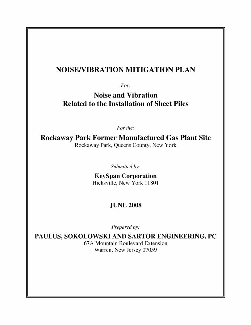
NOISE/VIBRATION MITIGATION PLAN
For:
Noise and Vibration
Related to the Installation of Sheet Piles
For the:
Rockaway Park Former Manufactured Gas Plant Site Rockaway Park, Queens County, New York
Submitted by:
KeySpan Corporation Hicksville, New York 11801
JUNE 2008
Prepared by:
PAULUS, SOKOLOWSKI AND SARTOR ENGINEERING, PC 67A Mountain Boulevard Extension
Warren, New Jersey 07059

i
P:\_Administrative\N\_FinalDocuments\Job#\C2522\J014-44\KJBENVMP.DOC
TABLE OF CONTENTS
1.0 INTRODUCTION .................................................................................................................1-1
1.1 Purpose................................................................................................................. 1-2
1.2 Summary of the Plan............................................................................................ 1-2
1.3 Noise Basics - Noise Descriptors......................................................................... 1-3
1.4 Vibration Basics................................................................................................... 1-4
1.5 Pile Driving Basics .............................................................................................. 1-5
1.6 Noise Standards ................................................................................................... 1-5
1.7 Community Nearby Receptors............................................................................. 1-9
2.0 PROJECT DESCRIPTION ...................................................................................................2-1
2.1 Site Description.................................................................................................... 2-1
2.2 Construction Activities and Equipment (Noise Sources) .................................... 2-2
2.3 Existing and Anticipated Noise ........................................................................... 2-4
2.4 Existing and Anticipated Vibration ..................................................................... 2-9
3.0 NOISE AND VIBRATION MITIGATION APPROACH ..................................................3-1
3.1 Tier 1- Mitigation Measures for General Site Construction ................................ 3-1
3.2 Tier 2- Mitigation Measures for Site-Specific Construction Activities............... 3-4
3.3 Tier 3- Focused Response Measures.................................................................... 3-5
3.3.1 Performance Measures............................................................................. 3-7
3.3.1.1 Vibration .................................................................................................. 3-7
3.3.1.2 Noise ........................................................................................................ 3-8
4.0 MONITORING PLAN..........................................................................................................4-1
4.1 Noise Monitoring ................................................................................................. 4-1
4.2 Vibration Monitoring ........................................................................................... 4-3
4.3 Access Agreements (Access to Nearby Receptors) ............................................. 4-5
5.0 REFERENCES ......................................................................................................................5-1
TABLES
Table 1-1 New York City Ambient Noise Quality Standards
Table 1-2 Human Reaction to Increases in Sound Pressure Levels
Table 2-1 Sheet Pile Driving Noise (Unmitigated)
Table 2-2 Building Classification Guidelines
Table 3-1 Action Levels
FIGURES
Figure 2-1 Noise and Vibration Distance Contours from Pile Driving associated with
DNAPL migration barrier alignments
Figure 2-2 Noise and Vibration Distance Contours from Pile Driving associated with
temporary excavation support sheet pile installation
Figure 4-1 Noise and Vibration Monitoring Locations

1-1
P:\_Administrative\N\_FinalDocuments\Job#\C2522\J014-44\KJBENVMP.DOC
1.0 INTRODUCTION
This Noise/Vibration Mitigation Plan (Plan) has been prepared by Paulus, Sokolowski and
Sartor, Engineering P.C. (PS&SPC) for KeySpan Corporation (KeySpan). The Plan presents the
proposed noise and vibration monitoring and mitigation measures to be implemented as part of
the remedial construction activities to be performed at the Rockaway Park Former Manufactured
Gas Plant (MGP) Site (Site) located in Rockaway Park, New York City, Borough of Queens
County, New York. The Site is bounded by Beach Channel Drive to the north, Beach 108th
Street to the east, and Rockaway Freeway to the south and west. South of Rockaway Freeway
are Metropolitan Transit Authority (MTA) subway tracks (elevated and ground level) and a rail
yard. Further to the south is a residential area of Rockaway Park. West of Rockaway Freeway
are properties occupied by auto service and retail businesses. East of Beach 108th
Street is a New
York City sewage treatment plant.
The remedial approach for the Site, as detailed in the Remedial Design Report (RDR) for the
Rockaway Park Former Manufactured Gas Plant Site, includes the installation of two Dense
Non-Aqueous Phase Liquid (DNAPL) migration barriers and performing shallow excavations to
depths of eight feet below grade surface (bgs) at select areas of the Site. These remedial
construction activities are being performed to address residual subsurface soil and groundwater
impacts resulting from historic MGP operations. The remedial action will consist of the
installation of two subsurface containment barrier systems (barrier) to contain DNAPL. The
barriers will consist of permanent Waterloo Barrier® steel sheet piling installed south of Beach
Channel Drive along the northern boundary of the site (On-site Area) and north of Beach
Channel Drive and to the south of Jamaica Bay (Bulkhead Area). Installation of the DNAPL
migration barrier along the northern edge of the Site will extend to a depth of 120 feet bgs in the
central portion of the Site and to 50 feet bgs on either side. Installation of the DNAPL migration
barrier along the Bulkhead Area will extend to a depth of 70 feet bgs. In addition, steel sheet
piles for temporary excavation support will be installed in three areas to a depth of 20 to 25 feet.
One section is along the southern site boundary to the south of the former gas works area, a
second section is along the southern and eastern site boundary adjacent to the former holder and
drip tank area and a third section is adjacent to the southeast corner of the electrical substation.

1-2
P:\_Administrative\N\_FinalDocuments\Job#\C2522\J014-44\KJBENVMP.DOC
These temporary sheet piles will be removed after excavation activities are completed. Refer to
design drawings for specific sheet pile installation locations.
The driving of the DNAPL migration barriers (i.e., steel sheet piles) and sheet piles for
temporary excavation support into the subsurface, as well as related construction activities, will
create noise and vibration at and adjacent to the drive location. During the start of sheet pile
driving, there tends to be a momentary peak in the noise level and then the noise is reduced as
the sheet is driven further into the ground, typically increasing ground-borne vibration.
1.1 Purpose
This Plan describes the various monitoring and mitigation measures to address potential
noise and vibration impacts to the immediate area as a result of steel sheet pile driving
and related sheet pile installation activities at the Site.
1.2 Summary of the Plan
This Plan incorporates practical and effective measures to offer the greatest potential to
mitigate noise and vibration from the planned pile driving activities at the Site. This Plan
includes the following elements:
• Noise and vibration monitoring;
• Scheduling of pile driving to restricted times;
• Use of a high frequency/variable moment vibratory hammer during sheeting
installation, where practicable;
• Limitations on pile driving methodologies; and,
• Use of action levels to evaluate potential noise and vibration impacts within the
community and to signal prescribed actions based on a tiered approach.
Additional mitigation measures may include:
• Use of Acoustic Insulation along the fence-line;
• Reduction of vibratory hammer load;
• Driving single sheet piles versus sheet piles in pairs; and,
• Focused inspections/monitoring.
1-3
P:\_Administrative\N\_FinalDocuments\Job#\C2522\J014-44\KJBENVMP.DOC
1.3 Noise Basics - Noise Descriptors
A number of noise descriptors are used to characterize various aspects of noise that take
into account the variability of noise levels over time. Common descriptors, criteria, and
guidelines used to characterize noise are discussed below.
A-Weighting (dBA) - Noise measurements are most often taken using the "A-weighted"
frequency response function. The A-weighted frequency or dBA scale simulates the
response of the human ear to sound levels (particularly low-level sound) and has been
given prominence as a means for estimating annoyance caused by noise; for estimating
the magnitude of noise-induced hearing damage; for use in hearing conservation criteria;
for speech interference measurements; and in procedures for estimating community
reaction to (general broadband) noise (Clayton, et al. 1978; Cheremisinoff, et al. 1977).
Sound measurements are often made using the “A” frequency weighting when assessing
environmental noise and commonly are expressed as the Leq or the LAeq (the A-
weighted equivalent continuous sound level).
Equivalent Sound Level (Leq) - The equivalent sound level (Leq) is the value of a
steady-state sound which has the same A-weighted sound energy as that contained in the
time-varying sound. The Leq is a single sound level value for a desired duration which
includes all of the time-varying sound energy during the measurement period. The U.S.
Environmental Protection Agency (EPA) has selected the Leq as the best environmental
noise descriptor primarily because it correlates reasonably well with the effects of noise
on people, even for wide variations of environmental sound levels and different time
exposure patterns.
Statistical Descriptors - Statistical sound level descriptors such as L10, L50, and L90 are
used to represent noise levels that are exceeded, 10, 50, and 90 percent of the time,
respectively. L50, the Sound Pressure Level (SPL) exceeded 50 percent of the time,
provides an indication of the median sound level. L90 represents the residual level, or the

1-4
P:\_Administrative\N\_FinalDocuments\Job#\C2522\J014-44\KJBENVMP.DOC
background noise level, without intrusive noises. The L10 is the sound level that is
exceeded 10 percent of the time for a specified monitoring period. The Lmax is the
maximum measured sound level at any instant in time.
1.4 Vibration Basics
Peak Particle Velocity (PPV) represents the maximum instantaneous positive or negative
peak of the vibration signal. The PPV is an appropriate measure for evaluating impulsive
vibration associated with vibration sources such as blasting or pile driving, and the
potential resulting stresses that may damage buildings. The U.S. Bureau of Mines
(USBM) criteria and methodology are applicable to this type of vibration measurement.
Excessive vibration levels from construction activities, although temporary in duration,
may create a nuisance condition at nearby sensitive receptors. Ground vibrations from
construction activities very rarely reach the levels that can damage structures. However,
the vibrations can reach audible and perceptible levels in buildings that are very close to
the active work area (DOT-T-95-16; April, 1995). Impact pile driving is one of the types
of construction activities that typically generate the greatest vibrations. Sheet pile driving
with a vibratory hammer, as proposed for use at this Site, typically generates less
vibration compared to pile driving using an impact hammer.
Annoyance from vibration often occurs when vibration levels exceed the thresholds of
human perception. These criteria are an order of magnitude below the damage threshold
for normal buildings and are well below vibration levels (0.50 in/sec PPV) at which
damage might be expected to occur. In other words, a person may be able to feel or
perceive vibration at levels that are much lower than levels that could cause damage. It is
important to note that the term “damage”, when used in the context of acceptable levels
of ground vibrations, refers to threshold damage as defined by the USBM. The definition
states “the occurrence of cosmetic damage; that is, the most superficial interior cracking
of the type that develops in all homes independent of blasting.” It also should be noted
that the occurrence of PPV values greater than the USBM threshold value (0.50 in/sec
PPV) does not imply that cosmetic cracking will occur, but that it could occur. Unless

1-5
P:\_Administrative\N\_FinalDocuments\Job#\C2522\J014-44\KJBENVMP.DOC
the initial monitoring indicates that cosmetic/hairline cracking occurs at PPV values
lower than the USBM criteria, these criteria can be considered applicable to “typical
residential structures”. For “fragile buildings” and “extremely fragile historic buildings”,
PPV values of 0.20 in/sec and 0.12 in/sec (at the building), respectively, have been
suggested.
1.5 Pile Driving Basics
The installation of piles is fairly common in modern construction projects. Piles are used
to support parking structures, bridges, overpasses, many types of buildings and also are
used as retaining structures or barriers. Piles often form the backbone of structures that
can serve as framework to support great weight and pressure of concrete loads. They can
be used as barriers that confine ground pressures and prevent unwanted movement.
Installing piles into the ground, as with other construction activities, cannot be done
without generating both noise and vibration. These activities can raise concern with
regard to the potential for off-site impacts to nearby receptors. Pile driving is, however, a
necessary construction activity.
Sheet pile driving consists of inserting a long, usually steel, sheet into the ground. A
common approach to accomplish this is with a vibratory hammer. This method makes
less noise than using an impact hammer. An impact hammer is a heavy weight hammer
that pounds on the pile creating sharp bang noises from the impact of the hammer on the
pile. The vibratory hammer does away with the sharp bang noise, as it “shakes” or
vibrates the pile into the ground. As such, it is considered to be quieter than an impact
hammer.
1.6 Noise Standards
New York City Code (Town of Rockaway Park)
Rockaway Park is situated in southern Queens, a Borough of New York City (NYC).
Construction noise is regulated by the New York City Noise Control Code and by the EPA
1-6
P:\_Administrative\N\_FinalDocuments\Job#\C2522\J014-44\KJBENVMP.DOC
noise emission standards for construction equipment. New York City has established an
enforceable noise code as amended in 2005 and currently effective (as of July 1, 2007).
New York City adopted Title 24 Chapter 2 as the New York City Noise Control Code.
Subchapter 1 Section 24-202 of the administrative code of the City of New York was
amended by Local Law No. 22 for the year 2002. Subchapter 2 Sections 24-204, 24-205,
24-206 and 24-207 and Subchapter 3 Section 24-218 of the administrative code of the City
of New York were amended by Local Law No. 18 for the year 1993. Subchapters 4, 5 and 6
of Chapter 2 of Title 24 of the code were repealed and new Subchapters 4, 5 and 6 were
added as amended by Local Law No. 113 for the year 2005 (effective July 1, 2007).
In addition to the Local Laws of the City of New York, the Rules of the City of New York
have been amended with the addition of new construction noise rules, written in
coordination with the new noise code and are effective as of July 1, 2007. Title 15 of the
Rules of the City of New York has been amended by adding a new Chapter 28, “Citywide
Construction Noise Mitigation,” which establishes a unique noise mitigation plan for each
construction site in order to have less noise impact on the surrounding environment. It
should be noted that this plan does not meet all the requirements of this rule and will require
an additional supplemented mitigation plan specific to the Site and equipment mobilized for
use at the Site. The contractor will be required to comply with the Local Laws and Rules of
the City of New York.
Construction noise is usually temporary and of relatively short duration. These local and
federal requirements mandate that certain classifications of construction equipment and
motor vehicles meet specified noise emissions standards. Also, except for special
circumstances, construction is limited to weekdays between the hours of 7 AM to 6 PM; and
that construction material be handled and transported so as to not create an unreasonable
noise as defined in Subchapter 5 Section 24-229. Section 24-228 in Subchapter 5
(Prohibited Noise-Specific Noise Sources-Sound Level Standard) states that construction,
exhausts and other devices shall not create an unreasonable noise, and defines unreasonable
1-7
P:\_Administrative\N\_FinalDocuments\Job#\C2522\J014-44\KJBENVMP.DOC
noise as sound attributable to the source or sources, that exceeds 85 dB(A) as measured 50
or more feet from the source or sources on a public right-of-way.
Subchapter 4 “Construction Noise Management” of Title 24 of the New York City noise
code imposes noise mitigation rules and requires a Noise Mitigation Plan for specific
devices or activities (i.e., air compressors, pile drivers, cranes, etc.). The provisions of this
code, including specific details and requirements, are discussed in Section 24-220 “Noise
Mitigation Plan” of the New York City Noise Code and Title 15 Chapter 28 “Citywide
Construction Noise Mitigation” of the rules of the City of New York.
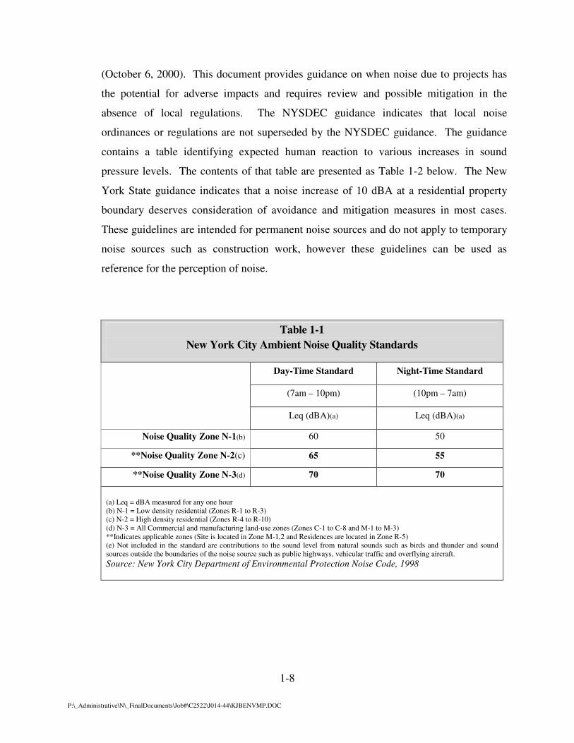
Ambient noise quality zones were formulated on the basis of present existing land-use
zones. Ambient noise quality criteria and standards are established and tabulated for each of
the three ambient noise quality zones. Table 1-1 presents the daytime and nighttime
standards according to zoning designation. The Project Site is located within a Noise
Quality Zone (N-3). A residential Noise Quality Zone (N-2) exists to the south of the Site
beyond Rockaway Freeway and the elevated MTA Line. The Site is bordered on the west
and east by commercial/industrial zones, Noise Quality Zone – N-3. Section 24-243 (b) (1)
(i) states that construction activities (listed in Section 24-219) conforming to Section 24-224
of the New York City Noise Code are exempt from these criteria and standards. This
section states that “Notwithstanding any other provision of this code, construction work
performed in accordance with a noise mitigation plan that is in full compliance with this
subchapter and such rules shall be deemed to be in compliance with all decibel level limits
set forth in other subchapters of this code.”
Construction activities, limited to the hours of operation on typical weekdays, will be
between 7:00 AM and 6:00 PM and will comply with the New York City Noise Code.
New York State
The New York State Department of Environmental Conservation (NYSDEC) has
published a policy and guidance document titled Assessing and Mitigating Noise Impacts
1-8
P:\_Administrative\N\_FinalDocuments\Job#\C2522\J014-44\KJBENVMP.DOC
(October 6, 2000). This document provides guidance on when noise due to projects has
the potential for adverse impacts and requires review and possible mitigation in the
absence of local regulations. The NYSDEC guidance indicates that local noise
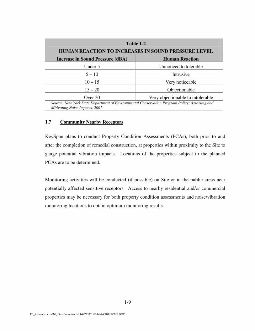
ordinances or regulations are not superseded by the NYSDEC guidance. The guidance
contains a table identifying expected human reaction to various increases in sound
pressure levels. The contents of that table are presented as Table 1-2 below. The New
York State guidance indicates that a noise increase of 10 dBA at a residential property
boundary deserves consideration of avoidance and mitigation measures in most cases.
These guidelines are intended for permanent noise sources and do not apply to temporary
noise sources such as construction work, however these guidelines can be used as
reference for the perception of noise.
Table 1-1
New York City Ambient Noise Quality Standards
Day-Time Standard Night-Time Standard
(7am – 10pm) (10pm – 7am)
Leq (dBA)(a) Leq (dBA)(a)
Noise Quality Zone N-1(b) 60 50
**Noise Quality Zone N-2(c) 65 55
**Noise Quality Zone N-3(d) 70 70
(a) Leq = dBA measured for any one hour
(b) N-1 = Low density residential (Zones R-1 to R-3)
(c) N-2 = High density residential (Zones R-4 to R-10)
(d) N-3 = All Commercial and manufacturing land-use zones (Zones C-1 to C-8 and M-1 to M-3)
**Indicates applicable zones (Site is located in Zone M-1,2 and Residences are located in Zone R-5)
(e) Not included in the standard are contributions to the sound level from natural sounds such as birds and thunder and sound
sources outside the boundaries of the noise source such as public highways, vehicular traffic and overflying aircraft.
Source: New York City Department of Environmental Protection Noise Code, 1998
1-9
P:\_Administrative\N\_FinalDocuments\Job#\C2522\J014-44\KJBENVMP.DOC
Table 1-2
HUMAN REACTION TO INCREASES IN SOUND PRESSURE LEVEL
Increase in Sound Pressure (dBA) Human Reaction
Under 5 Unnoticed to tolerable
5 – 10 Intrusive
10 – 15 Very noticeable
15 – 20 Objectionable
Over 20 Very objectionable to intolerable Source: New York State Department of Environmental Conservation Program Policy: Assessing and
Mitigating Noise Impacts, 2001
1.7 Community Nearby Receptors
KeySpan plans to conduct Property Condition Assessments (PCAs), both prior to and
after the completion of remedial construction, at properties within proximity to the Site to
gauge potential vibration impacts. Locations of the properties subject to the planned
PCAs are to be determined.
Monitoring activities will be conducted (if possible) on Site or in the public areas near
potentially affected sensitive receptors. Access to nearby residential and/or commercial
properties may be necessary for both property condition assessments and noise/vibration
monitoring locations to obtain optimum monitoring results.

2-1
P:\_Administrative\N\_FinalDocuments\Job#\C2522\J014-44\KJBENVMP.DOC
2.0 PROJECT DESCRIPTION
2.1 Site Description
Zoning - The Site is located within and surrounded by a commercial zone. However, the
Site is also located in proximity to a residential area, located to the south, across
Rockaway Freeway and the MTA Line. The boundary line delineating the two zones
runs between the residential properties and the MTA Line. Several commercial
businesses are located along Rockaway Freeway. The northwestern portion of the Site is
occupied by a KeySpan/LIPA electrical substation.
Sensitive Receptors
Potential noise/vibration receptors (residents) are located to the south (across Rockaway
Freeway and the MTA Line) of the Site. Two (2) commercial establishments are located
between 100 feet and 250 feet from the Site perimeter. An electrical substation is located
on the same property as where the remediation will occur, directly west of the on-site
DNAPL barrier alignment. The Rockaway Park Wastewater Treatment Plant is located
across Beach 108th
Street, directly east of the Site. The residences located south of
Rockaway Freeway are the closest residences to the Site. These residences are at
distances of 100 feet to 120 feet from the southern boundary of the Site and from the
planned alignment of sheet piles for temporary excavation support and 500 feet to 600
feet south of the planned on-site DNAPL migration barrier alignment. Commercial
establishments including a gas/service station on the corner of Beach Channel Drive and
Rockaway Freeway are located to the west of the Site, between 350 feet to 400 feet from
the planned on-site DNAPL migration barrier alignment and approximately 300 feet from
the planned alignment of sheet piles for temporary excavation support. Along the
northern property boundary of the Site is a pedestrian walkway along Beach Channel
Drive that could be impacted from pile driving operations.
There are three high-rise buildings (10 stories high) located south of Beach Channel
Drive between Beach 108th
Street and Beach 105th
Street. The closest high-rise building
is approximately 1,000 feet to 1,200 feet from the planned migration barrier alignment
2-2
P:\_Administrative\N\_FinalDocuments\Job#\C2522\J014-44\KJBENVMP.DOC
and approximately 600 feet from the planned alignment of sheet piles for temporary
excavation support. The other two buildings are farther away from the drive path and
partially shielded by the first building.
There are six (6) schools within an approximate half of a mile radius from the Site. The
closest school to the planned sheet pile alignment is less than 400 feet south of the Site,
the New York Community School District: Public School 225. The New York City
Community School District 27: Middle School 180 and the Active Learning Prep School
are 1500 feet east of the Site. Further northeast, an additional 1000 feet, are two high
schools. Queens Borough High School District: Beach Channel High School and the
New York Alternative High School District: NYC Vocational Training. An additional
school, Stella Maris High School, is located 800 feet southwest of the Site.
2.2 Construction Activities and Equipment (Noise Sources)
Remediation
The selected remedy to address known environmental impacts at the Site includes the
excavation of impacted materials and the construction of two subsurface vertical
containment barriers along the northern perimeter of the Site and along the Bulkhead
adjacent area. The first barrier, known as the On-Site Barrier, will extend approximately
695 linear feet and will be installed to two different depths. The center section of the On-
Site Barrier will extend to a depth of 120 feet bgs and two flanking 50 foot bgs barriers
will be installed on either side of the center section. A second barrier will be located
across Beach Channel Drive to the north in the Bulkhead Area. The second barrier,
known as the Bulkhead Barrier, will be installed within the Bulkhead Area to a depth of
70 feet bgs and a linear distance of approximately 170 feet. Both barriers will be
constructed using Waterloo Barrier®
steel sheet piling. In addition, steel sheet piles for
temporary excavation support will be installed in three sections to a depth of 20 to 25
feet. Installation of sheet piles for the various alignments is anticipated to occur
independently with little to no overlap. Excavation support sheet piles are temporary and

2-3
P:\_Administrative\N\_FinalDocuments\Job#\C2522\J014-44\KJBENVMP.DOC
will be removed after excavation activities are completed. Specific information regarding
installation of the DNAPL migration barriers is provided in Section 3.4 of the RDR.
A high-frequency vibratory hammer will be used at the Site for installation of the
DNAPL migration barrier and for installation of the temporary excavation support sheet
piles where practicable. It is anticipated that using a higher ranged frequency vibratory
hammer may result in less noise generated and cause less vibration.
Other Equipment - Noise associated with the installation of the vertical containment
barriers will be generated primarily by construction equipment and various construction
activities. Equipment utilized for pile driving and excavation activities includes an ABI
Mobilram TM18/22B pile driver, power packs, front-end loaders, backhoes, and other
construction-related vehicles and equipment. This equipment generates noise from diesel
engines, high-pressure air compressors, and mechanical equipment movement in general.
The most widespread source of noise from typical construction equipment is generally
due to internal combustion engines, usually diesel, which provide operating power.
Engine-powered construction equipment includes earthmoving equipment that is highly
mobile, handling equipment that is partly mobile, and stationary equipment. Earthmoving
equipment includes machinery such as drill rigs, excavators, loaders and dump trucks.
Their internal combustion engines are used both for propulsion and for powering working
mechanisms. Engine sound typically predominates, with exhaust noise normally being
the major source, and inlet sound level and structural sound level being of secondary
importance. Other sources of noise associated with the equipment include the back-up
alarms, mechanical and hydraulic transmission actuation systems and cooling fans that
can sometimes produce relatively high sound levels. The typical operating cycle of this
equipment often involves several minutes of full-power operation followed by several
minutes at lower power.
Stationary equipment such as air compressors, cranes, power packs and generators
generally run continuously at relatively constant power and speed, although sound levels
may vary according to the work cycle (e.g., loading). Because construction activities are

2-4
P:\_Administrative\N\_FinalDocuments\Job#\C2522\J014-44\KJBENVMP.DOC
carried out at various locations on the Site and because these activities change as work
progresses, the construction site will have both spatial and temporal noise dimensions.
Construction related noises are usually of a temporary duration and can be relatively
intermittent.
2.3 Existing and Anticipated Noise
Existing Noise Levels (Background)
Noise monitoring was performed in February 2006 during the completed pre-design field
demonstration program (pile driving activities) to establish existing noise levels in the
vicinity of the Site and to assess noise levels generated due to the proposed remedial
construction activities. This assessment provided an indication of pile driving related sound
levels that may be anticipated during the sheet pile installation activities.
Monitoring was performed at four (4) locations including: a location along Beach
Channel Drive on the northern boundary of the Site, a location on-site near the test
demonstration, a location along the southern property boundary of the Site nearby
residential receptors and a location near the KeySpan Rockaway Park Electrical
Substation located in the northwestern corner of the Site. Background measurements
were obtained during the morning and afternoon when on-site work was not in progress.
Monitored background sound levels (Leq; no sheet pile driving in progress) at the Site
ranged from approximately 60 dBA to 70 dBA. The range in background sound levels is
due to a compilation of monitoring data from several locations on-site and the proximity
of these locations to the roadway and other intrusive background sources. Residual sound
levels (L90) ranged from 55 dBA to 56 dBA. These sound levels may include noise from
operations at the electrical substation, noise from some light construction activity, noise
generated from local shops and pedestrians, overhead aircraft, vehicular traffic, and the
occasional commuter train on the MTA Line located to the south of the Site beyond
Rockaway Freeway.
2-5
P:\_Administrative\N\_FinalDocuments\Job#\C2522\J014-44\KJBENVMP.DOC
Existing noise sources - Background noise in the vicinity of the Site area of the Rockaway
Park community is predominantly from vehicular traffic (heavy vehicular traffic, cars,
trucks and buses idling at the nearby traffic light, automobile acceleration, loud mufflers, car
horns, loud car stereos, car alarms, brakes squealing, ambulance/police sirens, etc.). Noise
influences from off-site sources include: commercial shops and facilities (i.e., automotive
repair & service shop), pedestrians (people talking/yelling) and overhead aircraft. The on-
site electrical substation generates some low-level noise. Railroad tracks running east/west
are located to the south of the Site. These tracks are part of the MTA Line which runs
commuter trains over these tracks. Commuter trains are an intermittent sound source and of
short duration, with pass-bys of approximately one (1) minute.
Anticipated Noise Levels
Noise monitoring was performed at four (4) locations in the vicinity of the Rockaway Park
Site during a test/demonstration of full-length sheet piles in February 2006. The sheet pile
demonstration consisted of driving four (4) 120-foot sheet pile sections, consisting of two
(2) 60-foot sheet piles welded together, to a depth of 120 feet bgs using a vibratory hammer.
Once the completion depth (120 feet bgs) was reached for the four sheet pile sections, the
joints between sheet piles were flushed of sediment/debris.
Noise associated with the installation of the sheet piles was generated primarily by
construction equipment. Equipment utilized for this activity included heavy equipment
operation (i.e., large crane, jig lift, etc.), generators, vibratory hammer, welding equipment,
water pumps, trucks on-site and other construction-related vehicles and equipment.
Typical noise levels generated during the sheet pile driving demonstration are
summarized in Table 2-1 for several distances from the pile driving location and for
various driving depths. Typical unmitigated noise levels generated during sheet pile
driving have been summarized for a distance of approximately 80 to 120 feet from the
pile driving location. Monitored noise levels (Leq) ranged from approximately 70 dBA
to 73 dBA for driving single sheet piles to a depth of 60 feet. Monitored noise levels
(Leq) ranged from 78 dBA to 81 dBA for driving full-length welded sheet piles to a depth

2-6
P:\_Administrative\N\_FinalDocuments\Job#\C2522\J014-44\KJBENVMP.DOC
of 120 feet. Greater sound levels were observed when driving two sheet piles
simultaneously. These noise levels are based on noise monitoring performed at the Site
during the sheet pile driving test demonstration. The driving of single sheet piles at the
Site had a typical duration of 5 to 10 minutes. This information has been used to estimate
noise levels that can be expected at distances from the pile driving locations during
remedial construction implementation.
Projected noise levels are based on monitoring information of full-length and welded
sheet piles driven to a depth of 60 feet and 120 feet bgs, respectively, however the
temporary excavation support sheet piles are planned to be installed to a depth of 20 feet
to 25 feet bgs. The driving of a single excavation support sheet pile is anticipated to have
a typical duration of less than five minutes. Peak noise levels during the driving of
excavation support sheet piles are anticipated to be similar, if not slightly lower, than the
driving of full length sheet piles. In addition, the average duration of the drive time for a
25-foot sheet pile is almost half the time of a 60-foot sheet pile, therefore potential noise
impacts, if any, are anticipated to be short-lived. Retracting a single excavation support
sheet pile is anticipated to have a similar duration as the installation.
The monitored noise levels were used to estimate projected noise levels from pile driving
at various distances. Unmitigated Leq values at distances between 100 feet and 200 feet
from the source are between 72 to 80 dBA and 66 to 75 dBA, respectively. The Leq
values for driving full-length (60 foot section) sheet piles into the ground at distances
between 200 feet and 250 feet from the drive point are projected to be on the order of 72
dBA to 75 dBA. At a distance of greater than 200 feet from the drive point, the
maximum Leq values are not anticipated to be more than 75 dBA. Receptors within 200
feet of the drive path are anticipated to be exposed to unmitigated noise levels of
approximately 75 dBA or greater and receptors within 400 feet of the drive path may
experience unmitigated noise levels of approximately 68 dBA or greater. Beyond 400
feet from the drive path noise levels from pile driving activities are not anticipated to be
greater than 68 dBA.

2-7
P:\_Administrative\N\_FinalDocuments\Job#\C2522\J014-44\KJBENVMP.DOC
DNAPL Migration Barrier Alignment
Distance contours in 100 foot intervals (100, 200 feet, etc.) from the DNAPL migration
barrier alignment are shown on Figure 2-1 and illustrate the potential sensitive receptors
at these various distances. The closest commercial/industrial business is the wastewater
treatment plant located approximately 200 feet to 250 feet from the planned pile driving
pathways which could experience noise levels of approximately 75 dBA (Leq). At
distances of greater than 500 feet to 600 feet along the edge of the residential community
to the south, the noise level contributions from the pile driving are projected to be at or
less than 65 dBA (Leq). Noise levels from construction related activities at the closest
high-rise building, approximately 1,000 feet to 1,200 feet away from the DNAPL
migration barrier alignment, are projected to be 60 dBA or less.
Assuming planned pedestrian walkway closures are implemented adjacent to pile driving
activity, the pedestrian walkway across Beach Channel Drive is approximately 100 feet
from sheet pile driving activities and may experience sound levels on the order of 72
dBA to 80 dBA (Leq).
Excavation Support Sheet Pile Alignment
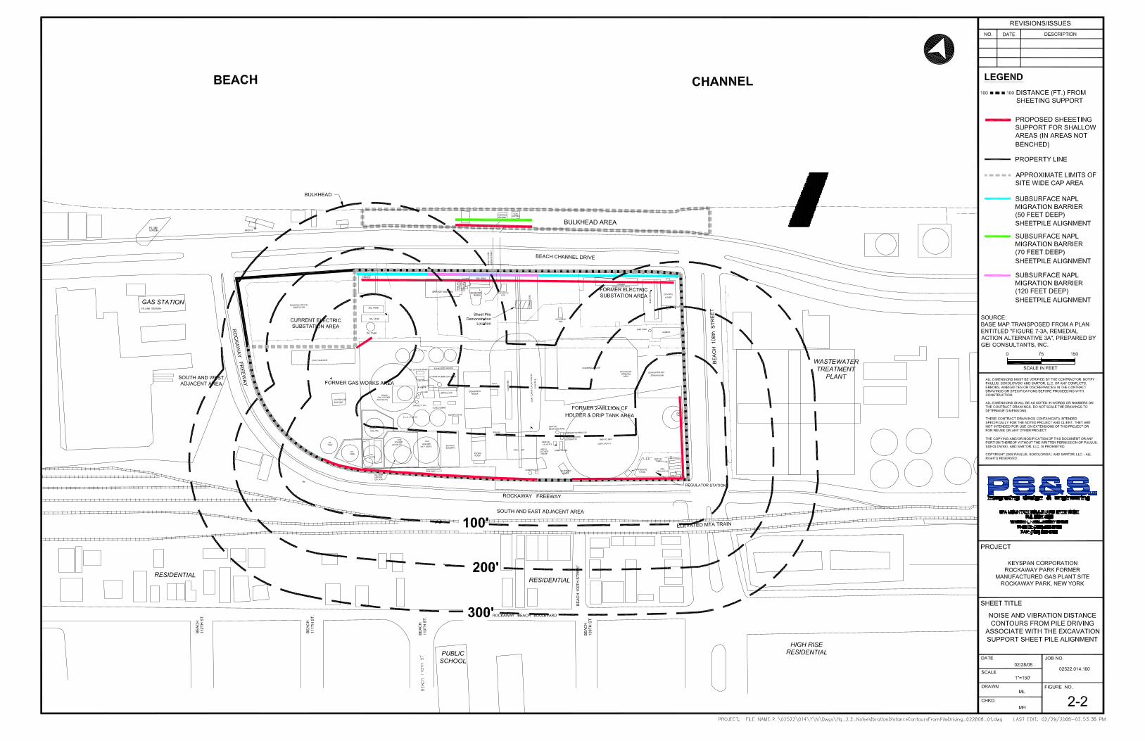
Distance contours in 100 foot intervals (100, 200 feet, etc.) from the planned temporary
excavation support sheet pile alignment are shown on Figure 2-2 and illustrate the
potential sensitive receptors at these various distances.
The closest commercial/industrial business is the wastewater treatment plant located
approximately 100 feet from the planned excavation support sheet pile alignment which
could experience noise levels of approximately 80 dBA.
The residential community to the south is approximately 100 feet from the southern
boundary of the site, the location of the planned alignment of sheet piles for temporary
excavation support. Noise at the residential properties may approach Leq sound levels as
great as 80 dBA. Noise levels at the closest high-rise building, approximately 600 feet

2-8
P:\_Administrative\N\_FinalDocuments\Job#\C2522\J014-44\KJBENVMP.DOC
from the planned alignment of sheet piles for temporary excavation support, are projected
to be 65 dBA or less. The closest school to the site is the New York Community School
District: Public School 225, approximately 400 feet south of the site. This school may
experience construction related noise levels of approximately 68 dBA to 70 dBA.
Driving of two or more sheet piles at the same time is not recommended. Noise
monitoring results from test demonstrations at representative Sites indicate that driving
two sheet piles at the same time generates noise on the order of 5 to 10 dBA greater than
driving single sheet piles.
In addition, noise from the pile driving varies in loudness and duration depending on the
specific driving activities, depth of the sheet in the ground, and the subsurface resistance
encountered. Difficulties with alignment of the migration barrier sheet piles due to
flexing of the sheets when encountering obstructive resistance to advancing the sheet
piles may contribute to additional noise. This can necessitate retracting sheet piles and
re-driving them to adjust alignment. Retracting, re-aligning, and re-driving sheet piles
can result in additional noise and add to the duration of noise from the sheet pile driving
process.
Table 2-1 Sheet Pile Driving Noise (Unmitigated)
Monitored Noise Levels Monitor distance to Pile
Driving Activity
Driving Depth Leq
(dBA)
L10
(dBA)
20 feet 60 feet 80.9 to 83.9 86.5 to 90.3
120 feet 60 feet 70.9 to 73.3 72.9 to 75.6
20 feet 120 feet 83.2 to 88.0 86.1 to 90.2
80 feet (a) 120 feet 81.5 83.1
120 feet (a)(b) 120 feet 78.1 79.9
150 feet (a)(b) 120 feet 78.3 81.2
Note: (a) Monitor was at this location (distance) for the driving of a single sheet (no range in data)
(b) These monitoring locations had a greater influence from traffic noise
Sound Levels measured at Rockaway Park Site during pile driving test demonstrations

2-9
P:\_Administrative\N\_FinalDocuments\Job#\C2522\J014-44\KJBENVMP.DOC
2.4 Existing and Anticipated Vibration
Existing Vibration
Vibration was also monitored at the Rockaway Park Site during pile driving
test/demonstrations performed in February 2006.
Existing vibration near the demonstration without pile driving were less than 0.02
inches/sec Peak Particle Velocity (PPV). The demonstration was performed on the
northern portion of the Site near the planned sub-surface mitigation barrier (sheet pile
drive path). It is anticipated that existing vibration along the southern Site boundary may
be higher due to the traffic and the proximity to the MTA Line.
Anticipated Vibration
Vibration monitoring was performed at several locations in the vicinity of the Rockaway
Park Site during a test/demonstration of full-length sheet piles in February 2006. Vibration
associated with the installation of the sheet piles was generated primarily by the vibratory
hammer.
Projected vibration levels are based on monitoring information of full-length and welded
sheet piles driven to a depth of 60 feet and 120 feet bgs, respectively, however the
temporary excavation support sheet piles are planned to be installed to a depth of 20 feet
to 25 feet bgs. The driving of a single excavation support sheet pile is anticipated to have
a typical duration of less than five minutes. Peak vibration during the driving of
excavation support sheet piles are anticipated to be similar, if not slightly lower, than the
driving of full length sheet piles. Retracting a single excavation support sheet pile is
anticipated to have a similar, if not slightly lower, peak vibration as the installation.
Maximum vibration monitored during the pile driving demonstrations ranged from 0.03
to 0.51 inches/sec PPV (inches/sec) at 15 feet from the drive location, from 0.02 to 0.22
inches/sec at 90 feet, from 0.02 to 0.17 inches/sec at 180 feet, and from 0.02 to 0.03
inches/sec at 390 feet.

2-10
P:\_Administrative\N\_FinalDocuments\Job#\C2522\J014-44\KJBENVMP.DOC
This information has been used to estimate vibration levels that can be expected at
specific distances from the pile driving locations during the remediation. This assumes
that subsurface soil conditions are consistent across the Site, and the Bulkhead Area, and
similar to the northern portion of the Site where the demonstrations were performed.
DNAPL Migration Barrier Alignment
Figure 2-1 shows the potentially sensitive receptors with distance contours (100 foot
intervals) from the DNAPL migration barrier alignment. Anticipated vibration concerns
due to pile driving near the electrical substation located in the northwestern corner of the
Site and near the wastewater treatment plant (east of the Site beyond Beach 108th
Street)
have been assessed.
It is not clear what PPV vibration threshold would be appropriate for the electrical
substation to prevent damage to sensitive components. It is expected that vibration from
pile driving near the substation could be mitigated to some degree by utilization of a
high-frequency vibratory hammer at 50% load. Pre-drilling the pathway near the
substation may serve to further minimize pile driving induced vibration.
The electrical substation is located approximately 20 feet from the closest sheet pile
alignment (vibration source) and the wastewater treatment plant is located approximately
200 feet from the migration barrier sheet pile alignment (vibration source). The boundary
of the electrical substation could experience PPV values as high as 0.51 in/sec. The
wastewater treatment plant could have PPV values as high as 0.17 in/sec. The
gas/service station is located approximately 400 feet from the migration barrier sheet pile
alignment and is not anticipated to experience impacts from vibration. Residents are
located approximately 600 feet from the DNAPL migration barrier alignment. Vibration
levels at this distance are not anticipated to be greater than 0.02 in/sec to 0.03 in/sec.
Temporary Excavation Support Sheet Pile Alignment
Figure 2-2 shows the potentially sensitive receptors with distance contours (100 foot
intervals) from the excavation support sheet pile alignment. The electrical substation is

2-11
P:\_Administrative\N\_FinalDocuments\Job#\C2522\J014-44\KJBENVMP.DOC
located approximately 20 feet from the excavation support sheet pile alignment (vibration
source) and the wastewater treatment plant is located approximately 100 feet from the
closest excavation support sheet pile alignment (vibration source). The boundary of the
electrical substation could experience PPV values as high as 0.51 in/sec. The wastewater
treatment plant could have PPV values as high as 0.22 in/sec. Residences are located
approximately 100 feet from the southern boundary of the site and from the planned
alignment of sheet piles for temporary excavation support. At a distance between 100
feet to 200 feet from the source, the PPV values are expected to be in the range of 0.17 to
0.22 in/sec. Residents may experience vibration levels in this range and may perceive
vibration.
At distances greater than 200 feet from the drive path, the maximum PPV values are
expected to be less than 0.17 in/sec, and at distances greater than 300 feet from the drive
path, the maximum PPV values are expected to be less than 0.12 in/sec. The USBM
defines a damage threshold value of 0.20 in/sec for fragile buildings. The USBM and the
Federal Transit Administration (FTA) define a damage threshold value for historic,
fragile buildings of 0.12 in/sec. PPV values greater than the 0.035 in/sec value may be
perceived by people.
Driving of two or more sheet piles at the same time is not recommended. Vibration
monitoring results from test demonstrations at representative Sites indicate that driving
two sheet piles at the same time can generate greater vibration than driving single sheet
piles.
In addition, vibration from the pile driving varies in intensity and duration depending on
the specific driving activities, depth of the sheet in the ground, and the subsurface
resistance encountered. Difficulties with alignment of the migration barrier sheet piles
when encountering obstructive resistance to advancing the sheet piles may contribute to
additional vibration. This can necessitate retracting sheet piles and re-driving them to
adjust alignment. Retracting, re-aligning, and re-driving sheet piles can result in
2-12
P:\_Administrative\N\_FinalDocuments\Job#\C2522\J014-44\KJBENVMP.DOC
additional vibration and add to the duration of vibration from the sheet pile driving
process.
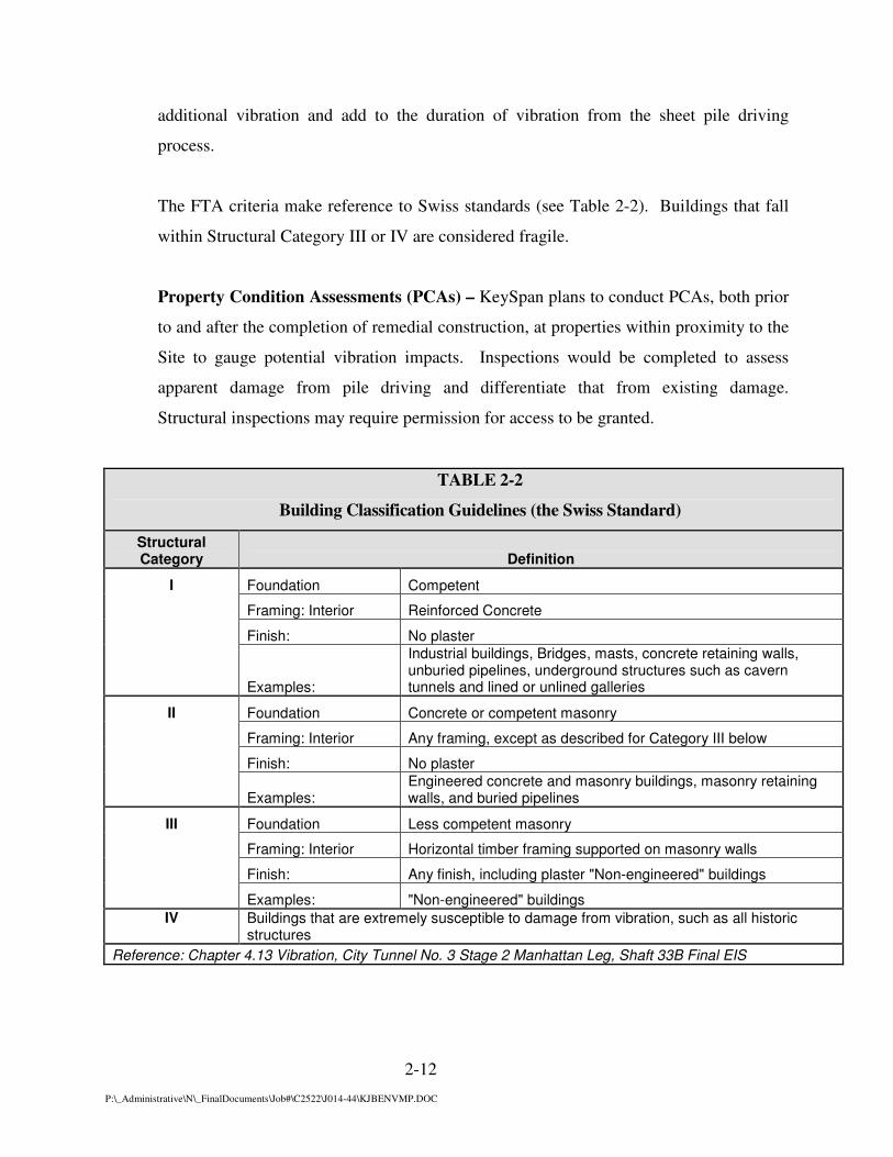
The FTA criteria make reference to Swiss standards (see Table 2-2). Buildings that fall
within Structural Category III or IV are considered fragile.
Property Condition Assessments (PCAs) – KeySpan plans to conduct PCAs, both prior
to and after the completion of remedial construction, at properties within proximity to the
Site to gauge potential vibration impacts. Inspections would be completed to assess
apparent damage from pile driving and differentiate that from existing damage.
Structural inspections may require permission for access to be granted.
TABLE 2-2
Building Classification Guidelines (the Swiss Standard)
Structural Category Definition
I Foundation Competent
Framing: Interior Reinforced Concrete
Finish: No plaster
Examples:
Industrial buildings, Bridges, masts, concrete retaining walls, unburied pipelines, underground structures such as cavern tunnels and lined or unlined galleries
II Foundation Concrete or competent masonry
Framing: Interior Any framing, except as described for Category III below
Finish: No plaster
Examples: Engineered concrete and masonry buildings, masonry retaining walls, and buried pipelines
III Foundation Less competent masonry
Framing: Interior Horizontal timber framing supported on masonry walls
Finish: Any finish, including plaster "Non-engineered" buildings
Examples: "Non-engineered" buildings
IV Buildings that are extremely susceptible to damage from vibration, such as all historic structures
Reference: Chapter 4.13 Vibration, City Tunnel No. 3 Stage 2 Manhattan Leg, Shaft 33B Final EIS


3-1
P:\_Administrative\N\_FinalDocuments\Job#\C2522\J014-44\KJBENVMP.DOC
3.0 NOISE AND VIBRATION MITIGATION APPROACH
Noise mitigation may be necessary to reduce off-site noise levels due to sheet pile driving. A
high-frequency vibratory hammer is to be utilized during the sheet pile driving to minimize noise
and vibration. In addition, the installation of sheet piles for the various alignments is anticipated
to occur independently with little to no overlap.
Due to the proximity of remedial activities, sidewalk closures are recommended for the sidewalk
adjacent to the Site on Beach Channel Drive. Pedestrian traffic will likely be diverted to the
northern side of Beach Channel Drive during pile driving along the Site boundary. Closures are
planned for the shoulder on the north side of Beach Channel Drive closest to the Bulkhead Area,
to traffic during pile driving of the Bulkhead Area DNAPL migration barrier.
Due to the temporal and spatial distribution of the sheet pile driving noise, and varying proximity
to local commercial business and residential dwellings, the mitigation approaches selected for
use at the Site consist of a combination of methods which will be implemented on a tiered
approach. Three primary tiers will be implemented, as necessary, to mitigate noise associated
with installation of sheet piles. A description of these measures, including applicability and
implementability, is presented below.
3.1 Tier 1- Mitigation Measures for General Site Construction
Initial (Tier 1) mitigation measures will be implemented from the start of sheet pile
driving related activities to address site-related construction noise levels. Tier 1 includes
general mitigation measures for construction operations as listed below and as outlined in
Title 15 Chapter 28 of the rules of the City of New York (NYCDEP 28-100 through 28-
109).
A complete and accurate general construction noise mitigation plan, in accordance with
Title 15 Chapter 28 of the Rules of the City of New York, “Citywide Construction Noise
Mitigation”, will be completed by the responsible party (contractor) and conspicuously
posted (NYCDEP 28-100). The Noise/Vibration Mitigation Plan Supplement to the

3-2
P:\_Administrative\N\_FinalDocuments\Job#\C2522\J014-44\KJBENVMP.DOC
Remedial Design Report for the Rockaway Park Former Manufactured Gas Plant Site
focuses on noise and vibration related to the installation of sheet piles, but does not
address the full requirements of the Rules of the City of New York. It is the
responsibility of the Site contractor to provide a Site and equipment specific mitigation
plan in accordance with the Title 15 Chapter 28 of the Rules of the City of New York,
“Citywide Construction Noise Mitigation,” which establishes a unique noise mitigation plan
for each construction site in order to have less noise impact on the surrounding environment.
Additionally, construction noise mitigation measures, in accordance with Title 15
Chapter 28 of the rules of the City of New York, will be followed. These required noise
mitigation measures for general construction, as per the NYC Noise Code (NYCDEP 28-
101), will include but not be limited to:
a. The responsible party will self-certify in its construction noise mitigation plan that all
construction tools and equipment have been maintained so that they operate at normal
manufacturer’s operating specifications, including at peak loading.
b. All construction equipment being operated on site must be equipped with the
appropriate manufacturer’s noise reduction device.
c. The responsible party shall mitigate noise from construction devices with internal
combustion engines by ensuring that the engine’s housing doors are kept closed, and by
using noise-insulating material mounted on the engine housing that does not interfere
with the manufacturer’s guidelines for engine operation or exhaust.
d. Portable compressors, generators, pumps and other such devices shall be covered with
noise-insulating fabric to the maximum extent possible that does not interfere with the
manufacturer’s guidelines for engine operation or exhaust.
e. Vehicle engine idling on site shall be prevented.
f. Quieter back-up alarms shall be used in pre-2008 model year vehicles when
practicable for the job site.
g. The contractor shall create and utilize a noise mitigation training program, which
shall be implemented for all field-worker supervisory personnel including sub-contractor
supervisors.

3-3
P:\_Administrative\N\_FinalDocuments\Job#\C2522\J014-44\KJBENVMP.DOC
h. Construction activities may take place during the hours of 7:00 AM to 6:00 PM on
weekdays.
Most modern construction equipment is equipped with engine noise control devices
(e.g., exhaust mufflers and acoustic casing enclosures) in accordance with Federal and
State regulations. In addition to proper maintenance and operation of construction
machinery, several means of controlling construction noise impacts will be employed as
needed, and as may be practical, including:
• Route heavily loaded truck traffic and heavy equipment movements to minimize
impacts on sensitive uses (i.e., use of County roads to the extent feasible);
• Operate earthmoving equipment on the site as far away from noise-sensitive
receptors as possible;
• Avoid nighttime activity - operate equipment during daylight hours to limit any
potential disturbance during the nighttime (sleep interference) periods, to the
extent possible, in accordance with the local Noise Ordinance; and
• Select demolition methods not involving impact, where possible (i.e., use of
concrete cutters (where practical), instead of pavement breakers, to minimize
noise associated with the removal of existing paved or concrete surfaces).
Use of a High Frequency/Variable Moment Vibratory Hammer
A higher-ranged frequency or variable moment hammer will likely result in incremental
reduction in noise generated and cause less vibration as compared to a standard vibratory
hammer. A high frequency/variable moment vibratory hammer was utilized during the
aforementioned field demonstration programs conducted at the Site. Monitoring will be
performed to evaluate the effect on noise and vibration and pile driving effectiveness.
Using a high-frequency hammer during driving near the electrical substation may provide
some mitigation to this area. Driving the sheet piles with a high frequency hammer may
be slower and may extend the sheet pile installation period.

3-4
P:\_Administrative\N\_FinalDocuments\Job#\C2522\J014-44\KJBENVMP.DOC
Tier 1 measures will be implemented until final restoration of the Site, after completion
of the pile driving activities.
3.2 Tier 2- Mitigation Measures for Site-Specific Construction Activities
Tier 2 mitigation measures include modifications to standard construction operation
practices based on specific work activities to be conducted at the Site. Tier 2 mitigation
measures include:
Reduction of Vibratory Hammer Load
Reducing the load on a vibratory hammer, both normal and high-frequency, has proven
beneficial at similar remediation sites and is an effective method of reducing both noise
and vibration. Reducing load, in combination with the use of a high-frequency vibratory
hammer, has shown to decrease pile-driving related noise and vibration.
Driving of Steel Sheet Piles in Singles vs. Pairs
Waterloo Barrier steel sheet piles driven in pairs (i.e., driving two steel sheets in unison)
during field demonstration programs produced incrementally greater noise than steel
sheet piles driven as single sheets. The noise generation differential can be attributed to
the additional force required to drive steel sheet piles in pairs versus a single steel sheet
pile and the flexing of the two sheet piles along the common connection point (i.e.,
sheeting interlock). As such, the Waterloo steel sheeting and temporary excavation
support sheeting utilized for the remedial construction work will be driven in single
sheets.
Fence – Acoustic Insulation
An acoustical insulation material can be attached to the inside of any construction-related
fencing, or supports (i.e., Jersey Barriers with fence-posts) that may be installed around

3-5
P:\_Administrative\N\_FinalDocuments\Job#\C2522\J014-44\KJBENVMP.DOC
the work area or can be attached to the inside of the chain link fence that runs along the
northern perimeter of the Site. This mitigation method may serve to suppress ground-
level noise generation and may decrease the potential noise levels (and visual impact) to
pedestrian foot traffic. The insulation would be BBC-13-2" Acoustical material (or
equivalent) that consists of a combination of 2" thick vinyl-faced Quilted Fiberglass
Sound Absorber and reinforced loaded vinyl noise barrier (1.5 pounds per square foot)
that are bonded together. The installed insulation can extend from the top of the fence to
the ground. Seams and joints would overlap approximately 2 inches and self seal with
Velcro strips. The insulation material has grommets installed which are used to fasten
the curtain material to the fence.
3.3 Tier 3- Focused Response Measures
Tier 3 mitigation includes the identification of focused measures to address localized
community feedback on a case-by-case basis. The objective of this approach is to
address the concerns of individual community members with mitigation measures
specific to their concern and/or circumstance. Tier 3 Measures are intended to be flexible
in their implementation and will require direct discussions with individual community
members. Some examples of potential Tier 3 Measures include:
Focused Inspections/Monitoring
As discussed in Section 1.7, KeySpan intends on completing PCAs for selected properties
within proximity to the Site. KeySpan also intends on conducting noise and vibration
monitoring at multiple locations along the perimeter of the Site. Based on the data
collected during these programs, and based on individual concerns, structures that are
deemed potentially vulnerable to the effects of pile driving may require inspections
and/or monitoring to verify and document existing conditions. In addition, supplemental
monitoring may be conducted immediately adjacent to these structures as well as other
structures based on community feedback and/or comparison to prescribed action levels.
3-6
P:\_Administrative\N\_FinalDocuments\Job#\C2522\J014-44\KJBENVMP.DOC
Interior/Exterior Treatments
Treatments may include the placement of flexible coverings or acoustic materials on
interior/exterior openings, windows and/or portions of the walls of businesses or
residential dwellings in close proximity to sheet pile installation. Treatment options will
likely require additional property access and the cooperation of the affected building
owners and/or residents.
Temporary Sound Barriers
Small-scale moveable and/or fixed barriers can be erected at locations north of the Site
perimeter (e.g., south side of Beach Channel Drive). These barriers, which may be
located on public rights-of-way, would be relatively low-profile and consist of sound
attenuating material affixed to stationary or moveable platforms or stands. The exact
construction and location of these barriers will be dependent on the presence of above-
ground obstructions (and overhead utilities), the existence of viable access points, the
nature of the building or use in question and the results of any focused monitoring.
Mitigation Measures Not Selected For Use:
Noise mitigation is planned to reduce offsite noise levels due to sheet pile driving
operations. A number of potential mitigation measures were evaluated to determine both
their overall effectiveness and their applicability to the Site. Mitigation measures which
were evaluated and not selected for use include:
• Moveable Sound Curtain Barrier- use of a moveable acoustical curtain that
would shield offsite receptors from potential noise was deemed impractical due
to site-specific constraints. Specifically, the proximity of overhead lines and the
proximity of the heavily traveled Beach Channel Drive preclude the safe
application of this technology. In addition, the closest receptors are located at
such a distance that this type of mitigation may not prove beneficial based on the
additional time expended for mobilization/de-mobilization and weather
constraints.

3-7
P:\_Administrative\N\_FinalDocuments\Job#\C2522\J014-44\KJBENVMP.DOC
• Temporary Noise Barrier- use of an on-site physical barrier to temporarily shield
noise generated sources (e.g., stackable cargo/freight boxes) was deemed
impractical due to the proximity of overhead lines and heavily traveled Beach
Channel Drive.
• Pre-Drilling or Jetting of Steel Sheeting- use of drilling or water/air jetting in the
vertical path of the proposed steel sheeting to facilitate the driving of steel
sheeting was deemed ineffective at the Site due to the presence of sandy soils at
depth. Pre-drilling, although not proven entirely effective, may be beneficial as a
contingency in the northwestern corner of the Site to minimize vibration at the
electrical substation if other means of controlling vibration are not effective.
• Impact Hammer to Drive Sheeting- use of an impact hammer to drive steel
sheeting was not selected based on the comparatively excessive noise generation
from the use of an impact hammer during representative field demonstration
programs. One exception, however, is that the MTA may require the use of an
impact hammer for pile driving in proximity to the railroad right-of-way. Pile
driving the excavation support sheet piles along the southern boundary of the site
will be within 100 feet of the railroad right-of-way. The applicability of this
requirement is still to be determined.
3.3.1 Performance Measures
Noise and vibration monitoring will be performed during pile driving activities.
Noise and vibration threshold levels, and the actions to be taken if these threshold
levels are exceeded, are described below. Table 3-1 identifies the noise and
vibration action level thresholds and prescribed actions.
3.3.1.1 Vibration
Two vibration “action level” threshold values will be used to assess the potential
vibration during pile driving at the Site. These levels will be evaluated at the
ground surface by the maximum of the longitudinal, transverse, and vertical
direction outside and near the foundations of potentially impacted structures, as
practical. The distances at which action levels are to be assessed will be based on
field logistics.

3-8
P:\_Administrative\N\_FinalDocuments\Job#\C2522\J014-44\KJBENVMP.DOC
3.3.1.2 Noise
Three “action” noise threshold values will be used to assess the effectiveness of
mitigation measures during pile driving at the Site. Monitoring to assess the
threshold noise levels will be the Leq, measured/evaluated outdoors between
sensitive receptors and the pile driving activity at the Site using a 10 minute
average. Placement of monitors near sensitive receptors will provide data on
noise and vibration in these areas. Measured sound levels based on a monitored
10 minute average will be compared to the action levels. The distances at which
action levels are to be assessed will be based on field logistics.

3-9
P:\_Administrative\N\_FinalDocuments\Job#\C2522\J014-44\KJBENVMP.DOC
Table 3-1
ACTION LEVELS
VIBRATION
Action
Vibration
Threshold Values
(Inches per
Second PPV)
Remarks
“Warning” 0.2
The vibration “warning” threshold level is 0.2 inches per second
PPV. If this level is exceeded then the situation will be reviewed
to identify the potential cause.
“Temporary Halt” 0.5
The vibration “stop work” threshold is 0.5 inches per second PPV.
This threshold level is the U.S. Bureau of Mines vibration criteria
to avoid possible cosmetic damage to structures with concrete
foundations, timber framing. The potential causes of such
vibration will be reviewed and possible mitigation methods
investigated.
NOISE Action Noise Threshold
Values
(Leq dBA)
Remarks
“Monitoring” 80
Tier 1 Mitigation Methods will be employed.
Field monitoring will continue to be implemented as planned.
“Warning” 85
Tier 1 and possibly Tier 2 Mitigation Measures will continue to be
employed.
Field monitoring will continue to be implemented as planned.
If exceeded, potential causes will be investigated. If the cause is
due to equipment or operation factors, then these would be
corrected.
“Temporary Halt” 90
Tier 1 and Tier 2 Mitigation Measures will continue to be
employed.
If this action level is exceeded, Tier 3 Mitigation Measures will be
evaluated for use, as appropriate.
(Note that Tier 3 Mitigation Measures may be implemented at
lower Noise Threshold Values as determined by KeySpan)
4-1
P:\_Administrative\N\_FinalDocuments\Job#\C2522\J014-44\KJBENVMP.DOC
4.0 MONITORING PLAN
Noise and vibration monitoring will be performed to assess potential community impacts and to
establish a data record for implementing mitigation measures. Monitoring will be performed for
noise and vibration during pile driving and related construction activities. The addition of
monitors in proximity or within the commercial areas will provide necessary data on noise and
vibration in the areas closest to receptors (residents/electrical substation/WWTP) and will
provide data for comparing the noise and vibration levels with their respective action levels.
4.1 Noise Monitoring
The planned remedial construction activities will be performed so as to limit the potential
for adverse impacts due to noise. The installation of the subsurface DNAPL migration
barrier and temporary excavation support sheet piles, and the extraction of temporary
excavation support sheet piles, will increase noise levels above background conditions.
Noise monitoring will be conducted during all sheet pile driving activities being
implemented as part of the proposed remedial construction activities. Pending access
approval, noise will be monitored at various locations in the vicinity of pile driving
activities (Figure 4-1) as well as at selected locations on-site to be determined in the field.
The number and locations of monitoring points may be adjusted as the field work
progresses to obtain the most representative data in proximity to sensitive receptors.
Monitors may be re-located based on the different sheet pile segments and specific
location of the sheet pile installation during each segment (Figure 4-1). Re-location of
monitoring equipment will also depend upon field logistics and access to adjacent
properties.
Noise monitoring will be performed using a Type 1 instrument in accordance with the
American National Standards Institute (ANSI), S1.4-1983 Type 1. The sound level
meters to be used are capable of collecting a wide range of measurements, take several
measurements simultaneously and automatically store data at the end of a pre-set time
period. Monitoring will be conducted continuously during pile driving and related

4-2
P:\_Administrative\N\_FinalDocuments\Job#\C2522\J014-44\KJBENVMP.DOC
construction activities. Results of the monitoring will be collected and reviewed
throughout the monitoring period.
Noise monitoring will not be performed during inclement weather (i.e., downpours or
when wind speeds are greater than 12 to 15 mph). Inclement weather includes winds in
excess of 15 mph and precipitation. Inclement weather can cause erroneous sound level
measurements. The sound level instrumentation (i.e., microphone) is not waterproof and
can be damaged due to precipitation. Condensation can cause arcing which results in
false readings. Placing bags over the microphone windscreen is a temporary solution,
can cause a build-up of condensation in the bag, and will result in erroneous readings
from the sound of raindrops impacting the bag. Wet pavement can also cause higher
sound level readings resulting from tire noise. In addition, rain impacts the ability of the
microphone to collect other sounds, and can mask the monitor’s ability to capture other
noise readings.
It is not recommended to take sound level measurements when the wind speed exceeds
15 mph as excessive wind can create noise (i.e., fluctuations in wind pressure) and block
the monitor’s ability to record other sounds, making the possibility of extracting noise
information about the Site difficult.
The sound level monitoring system is equipped with a special windscreen material that
repels rain and protects the microphone from light precipitation, and includes a
desiccated chamber to preserve performance in high humidity environments. However,
during rain events, moisture may still reach the microphone through the windscreen;
therefore monitoring during rain events is not recommended. The windscreen is designed
to protect the microphone from winds up to approximately 15 mph.
During monitoring, the following procedures will be followed:

4-3
P:\_Administrative\N\_FinalDocuments\Job#\C2522\J014-44\KJBENVMP.DOC
• Noise Measurements will be performed using the A-weighting network and the
"slow" response of the sound level meter.
• The microphone will be fitted with a windscreen.
• The Noise Monitoring will be measured at approximately four to five feet above
the ground surface.
• Monitoring will be performed at least five to ten feet away from the nearest
acoustically-reflective surface (i.e., fences, buildings).
• Noise level measurements will be taken at each monitoring location during sheet
pile installation activities continually during the daytime.
• Leq noise measurements will be computed.
• Noise measurements will be performed during the construction activity that has
the greatest noise potential (i.e., pile driving).
• Noise measurement data will be stored electronically and summarized with notice
upon request (i.e., tables, plotted graphically, etc.).
• Construction activities observed during noise monitoring will be noted.
Noise monitoring equipment will be operated, maintained and calibrated in accordance
with the manufacturer’s instructions and the established quality assurance procedures.
Noise monitoring equipment will be checked daily for proper operation. Field validation
logs will be maintained on-site.
4.2 Vibration Monitoring
The remedial construction activities will be performed so as to limit the potential for
adverse impacts due to vibration. During the installation of the subsurface containment
barrier, the driving of sheet piles has the potential to create increased ground vibration.
Vibration monitoring will be conducted during all sheet pile driving as part of the
planned remedial construction activities. Vibration will be monitored along the perimeter
of the installation area and at varying distances from the sheet pile driving activities
and/or near sensitive structures/receptors in close proximity to the sheet pile driving

4-4
P:\_Administrative\N\_FinalDocuments\Job#\C2522\J014-44\KJBENVMP.DOC
activity (Figure 4-1). Potential sensitive receptors include, but are not limited to, adjacent
residential and business structures. The number and locations of monitoring points may
be adjusted as the field work progresses to obtain the most representative data in
proximity to sensitive receptors. Monitors may be re-located based on the different sheet
pile segments and specific location of the sheet pile installation during each segment
(Figure 4-1). Re-location of monitoring equipment will also depend upon field logistics
and access to adjacent properties.
Vibration monitoring will be performed using a seismograph, an instrument that records
vibration in the subsurface, to examine the extent of vibration from the sheet pile driving
operations and contractors’ general construction procedure. Ground-borne vibration levels
will be measured using a portable seismograph (or similar unit). The seismograph
instrument is a continuous monitor recording PPV data. The seismograph can detect and be
triggered by low levels of vibration.
A vibration criterion of 0.5 inches per second (in/sec) peak particle velocity (PPV) is
proposed as the applicable action threshold criteria for ground-borne vibration
measurement during proposed remedial construction activities. The 0.5 in/sec PPV
criterion has been established by the USBM as the threshold above which damage to
interior plaster walls may occur. This criterion has become recognized by industry as the
threshold for the onset of vibration damage to typical residential structures.
Collected vibration monitoring results will be compared to the vibration criterion. The
results will also be tabulated and reviewed on a weekly basis to assess trends and
formulate the basis for mitigation measures, if required.
The vibration monitoring and surveillance equipment will be operated, maintained and
calibrated in accordance with the manufacturer’s instructions and the established quality
assurance procedures. Seismic monitoring equipment will be checked daily for proper
operation. Field validation logs will be maintained on-site.

4-5
P:\_Administrative\N\_FinalDocuments\Job#\C2522\J014-44\KJBENVMP.DOC
4.3 Access Agreements (Access to Nearby Receptors)
Access to sensitive receptors (commercial businesses/residences) properties may be required
during installation of sheet piles for temporary excavation support. Monitoring will be
performed at adjacent areas along the boundary of the Site where practicable. However,
access to nearby commercial properties may be necessary for optimum placement of
monitoring devices and assessment of potential impacts. If access to sensitive receptor
properties (commercial/residential) can not be granted, use of adjacent publicly accessible
areas will be considered and evaluated.


5-1
P:\_Administrative\N\_FinalDocuments\Job#\C2522\J014-44\KJBENVMP.DOC
5.0 REFERENCES
Bolt, Beranek, and Newman, Inc. 1978. Electric Power Plant Environmental Noise Guide -
Volume I. Edison Electric Institute.
Brüel & Kjær. October 1991. Instruction Manual: Modular Precision Sound Level Meter Type 2231
Plus Statistical Analysis Module BZ7115. Brüel & Kjær. January 1987. Instruction Manual:
1/3 - 1/1 Octave Filter Set Type 1625
Cheremisinoff, P.N. and P.P. Cheremisinoff. 1977. Industrial Noise Control Handbook. Ann
Arbor Science Publishers, Inc.
Clayton, G.D. and F.E. Clayton (Editors). 1978. Volume I: General Principles - Patty's Industrial
Hygiene and Toxicology, Third Revised Edition. John Wiley & Sons, Inc.
Federal Transit Administration. April 1995. Transit Noise and Vibration Impact Assessment.
Prepared by Harris Miller and Hanson, Inc. for the Office of Planning, Federal Transit
Administration, U.S. Department of Transportation, DOT-T-95-16.
Greenberg, M.R.; G. Belnay; W. Chesanek; N. Neuman; and G. Sheperd. 1979. A Primer on
Industrial Environmental Impact. The Center of Urban Policy Research, Rutgers
University.
Mayor's Office of Environmental Coordination. October 2001. City Environmental Quality Review
Technical Manual. Section 3R: Noise.
(Noise Control Guide 1980)
New York City Department of Environmental Protection (NYDEP). 1998. “New York City Noise
Code,” March 1998.
Department of Environmental Conservation (NYSDEC). 2001. “Assessing and Mitigating Noise
Impacts - PROGRAM POLICY”, Department ID:DEP-00-1, October 6, 2000 Revised:
February 2, 2001.
Peterson, A.P.G. and E.G. Gross. 1972. Handbook of Noise Measurement. General Radio
Company.
(SOUND BASICS MPCA May 1983 NPC)
US Bureau of Mines. DOT-T-95-16; April 1995.
U.S. Environmental Protection Agency. 1971. Noise from Construction Equipment. NTID 300.1.
U.S. Environmental Protection Agency. March 1974. Information on Levels of Environmental
Noise Requisite to Protect Public Health and Welfare with an Adequate Margin of Safety.
EPA 550/9-74-004.

5-2
P:\_Administrative\N\_FinalDocuments\Job#\C2522\J014-44\KJBENVMP.DOC
U.S. Environmental Protection Agency. November 1978. Protective Noise Levels - Condensed
Version of EPA Levels Document. EPA 550/9-79-100.
U.S. Environmental Protection Agency. 1977
U.S. Bureau of Mines. 1980. Structure Response and Damage Produced by Ground Vibrations
from Surface Blasting. U.S. Department of the Interior, U.S. Bureau of Mines, Report of
Investigations 8507.
U.S. Bureau of Mines. DOT-T-95-16; April 1995.